EP2805437B1 - Apparatus and method for pilot scrambling for enhanced physical downlink control channels - Google Patents
Apparatus and method for pilot scrambling for enhanced physical downlink control channels Download PDFInfo
- Publication number
- EP2805437B1 EP2805437B1 EP13738676.9A EP13738676A EP2805437B1 EP 2805437 B1 EP2805437 B1 EP 2805437B1 EP 13738676 A EP13738676 A EP 13738676A EP 2805437 B1 EP2805437 B1 EP 2805437B1
- Authority
- EP
- European Patent Office
- Prior art keywords
- epdcch
- pdcch
- prbs
- scrambling
- scrambling initialization
- Prior art date
- Legal status (The legal status is an assumption and is not a legal conclusion. Google has not performed a legal analysis and makes no representation as to the accuracy of the status listed.)
- Active
Links
Images


Classifications
-
- H—ELECTRICITY
- H04—ELECTRIC COMMUNICATION TECHNIQUE
- H04B—TRANSMISSION
- H04B7/00—Radio transmission systems, i.e. using radiation field
- H04B7/24—Radio transmission systems, i.e. using radiation field for communication between two or more posts
- H04B7/26—Radio transmission systems, i.e. using radiation field for communication between two or more posts at least one of which is mobile
- H04B7/2603—Arrangements for wireless physical layer control
-
- H—ELECTRICITY
- H04—ELECTRIC COMMUNICATION TECHNIQUE
- H04W—WIRELESS COMMUNICATION NETWORKS
- H04W24/00—Supervisory, monitoring or testing arrangements
- H04W24/02—Arrangements for optimising operational condition
-
- H—ELECTRICITY
- H04—ELECTRIC COMMUNICATION TECHNIQUE
- H04W—WIRELESS COMMUNICATION NETWORKS
- H04W48/00—Access restriction; Network selection; Access point selection
- H04W48/08—Access restriction or access information delivery, e.g. discovery data delivery
- H04W48/12—Access restriction or access information delivery, e.g. discovery data delivery using downlink control channel
Definitions
- the present application relates generally to wireless communications and, more specifically, to a system and method for pilot signal scrambling for enhanced physical control channels.
- LTE Long Term Evolution
- UE user equipment
- DL downlink
- UE-RS UE-specific demodulation reference signals
- DM RS sequence setting for downlink CoMP 3GPP DRAFT; R1-113957 DL DM RS SEQUENCE, 3RD GENERATION PARTNERSHIP PROJECT (3GPP)
- VCI virtual Cell ID
- UE-specific higher-layer signaling can be used to configure a VCI value.
- DL DM-RS sequence for Rel-11 CoMP 3GPP DRAFT; R1-114074 COMP DMRS, 3RD GENERATION PARTNERSHIP PROJECT (3GPP)
- a UE can be semi-statically configured in a UE specific manner, where initialization values for DMRS scrambling generator are available for dynamic selection. Initialization values can be configured to correspond to Rel-10 DMRS.
- a parameter "X" can be used in a UE specific manner: (1) add UE-specific information, (2) replace cell ID to UE-specific information, or (3) add UE-specific information into cell ID place.
- a base station configured to communicate with a plurality of base stations via a backhaul link and configured to communicate with a plurality of user equipments.
- the base station includes a transmit path configured to transmit data, reference signals, synchronization signals and control elements to at least one of the plurality of subscriber stations.
- the base station also includes processing circuitry configured to configure enhanced physical downlink control channel (e-PDCCH) DMRS parameters for each of a plurality of e-PDCCH sets.
- e-PDCCH enhanced physical downlink control channel
- a method for mapping synchronization signals includes transmitting data, reference signals, synchronization signals and control elements to at least one of the plurality of subscriber stations.
- the method also includes configuring enhanced physical downlink control channel (e-PDCCH) DMRS parameters for each of a plurality of e-PDCCH sets.
- e-PDCCH enhanced physical downlink control channel
- a subscriber station configured to communicate with at least one base station, which is configured to communicate with a plurality of base stations via a backhaul link, is provided.
- the subscriber station includes receiver configured to receive data, reference signals, synchronization signals and control elements from the base station.
- the subscriber station also includes processing circuitry configured to read physical resource blocks (PRBs) containing enhanced physical downlink control channel (e-PDCCH) downlink modulated reference signals (DMRS) parameters that have been configured for each of a plurality of e-PDCCH sets.
- PRBs physical resource blocks
- e-PDCCH enhanced physical downlink control channel
- DMRS downlink modulated reference signals
- FIGURES 1 through 11 discussed below, and the various embodiments used to describe the principles of the present disclosure in this patent document are by way of illustration only and should not be construed in any way to limit the scope of the disclosure. Those skilled in the art will understand that the principles of the present disclosure may be implemented in any suitably arranged wireless communication system.
- FIGURE 1 illustrates a wireless network 100 according to one embodiment of the present disclosure.
- the embodiment of wireless network 100 illustrated in FIGURE 1 is for illustration only. Other embodiments of wireless network 100 could be used without departing from the scope of this disclosure.
- the wireless network 100 includes eNodeB (eNB) 101, eNB 102, and eNB 103.
- the eNB 101 communicates with eNB 102 and eNB 103.
- the eNB 101 also communicates with Internet protocol (IP) network 130, such as the Internet, a proprietary IP network, or other data network.
- IP Internet protocol
- eNodeB eNodeB
- base station eNodeB
- access point eNodeB
- eNodeB eNodeB
- UE user equipment
- remote terminals that can be used by a consumer to access services via the wireless communications network.
- Other well know terms for the remote terminals include “mobile stations” and “subscriber stations.”
- the eNB 102 provides wireless broadband access to network 130 to a first plurality of user equipments (UEs) within coverage area 120 of eNB 102.
- the first plurality of UEs includes UE 111, which may be located in a small business; UE 112, which may be located in an enterprise; UE 113, which may be located in a WiFi hotspot; UE 114, which may be located in a first residence; UE 115, which may be located in a second residence; and UE 116, which may be a mobile device, such as a cell phone, a wireless laptop, a wireless PDA, or the like.
- UEs 111-116 may be any wireless communication, device, such as, but not limited to, a mobile phone, mobile PDA and any mobile station (MS).
- the term “user equipment” or “UE” is used herein to designate any remote wireless equipment that wirelessly accesses an eNB, whether the UE is a mobile device (e.g., cell phone) or is normally considered a stationary device (e.g., desktop personal computer, vending machine, etc.).
- UE user equipment
- MS mobile station
- SS subscriber station
- RT remote terminal
- WT wireless terminal
- the eNB 103 provides wireless broadband access to a second plurality of UEs within coverage area 125 of eNB 103.
- the second plurality of UEs includes UE 115 and UE 116.
- one or more of eNBs 101-103 may communicate with each other and with UEs 111-116 using LTE or LTE-A techniques including techniques for: pilot scrambling for enhanced physical downlink control channels (e.g., e-PDCCH scrambling) described in embodiments of the present disclosure.
- Dotted lines show the approximate extents of coverage areas 120 and 125, which are shown as approximately circular for the purposes of illustration and explanation only. It should be clearly understood that the coverage areas associated with base stations, for example, coverage areas 120 and 125, may have other shapes, including irregular shapes, depending upon the configuration, of the base stations and variations in the radio environment associated with natural and man-made obstructions.
- FIGURE 1 depicts one example of a wireless network 100
- another type of data network such as a wired network
- network terminals may replace eNBs 101-103 and UEs 111-116.
- Wired connections may replace the wireless connections depicted in FIGURE 1 .
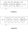
- FIGURE 2A is a high-level diagram of a wireless transmit path.
- FIGURE 2B is a high-level diagram of a wireless receive path.
- the transmit path 200 may be implemented, e.g., in eNB 102 and the receive path 250 may be implemented, e.g., in a UE, such as UE 116 of FIGURE 1 .
- the receive path 250 could be implemented in an eNB (e.g. eNB 102 of FIGURE 1 ) and the transmit path 200 could be implemented in a UE.
- transmit path 200 and receive path 250 are configured to perform methods for pilot scrambling for enhanced physical downlink control channels described in embodiments of the present disclosure.
- Transmit path 200 comprises channel coding and modulation block 205, serial-to-parallel (S-to-P) block 210, Size N Inverse Fast Fourier Transform (IFFT) block 215, parallel-to-serial (P-to-S) block 220, add cyclic prefix block 225, up-converter (UC) 230.
- Receive path 250 comprises down-converter (DC) 255, remove cyclic prefix block 260, serial-to-parallel (S-to-P) block 265, Size N Fast Fourier Transform (FFT) block 270, parallel-to-serial (P-to-S) block 275, channel decoding and demodulation block 280.
- DC down-converter
- FFT Fast Fourier Transform
- FIGURES 2A and 2B may be implemented in software while other components may be implemented by configurable hardware (e.g., a processor) or a mixture of software and configurable hardware.
- configurable hardware e.g., a processor
- the FFT blocks and the IFFT blocks described in this disclosure document may be implemented as configurable software algorithms, where the value of Size N may be modified according to the implementation.
- the value of the N variable may be any integer number (i.e., 1, 2, 3, 4, etc.), while for FFT and IFFT functions, the value of the N variable may be any integer number that is a power of two (i.e., 1, 2, 4, 8, 16, etc.).
- channel coding and modulation block 205 receives a set of information bits, applies coding (e.g., LDPC coding) and modulates (e.g., Quadrature Phase Shift Keying (QPSK) or Quadrature Amplitude Modulation (QAM)) the input bits to produce a sequence of frequency-domain modulation symbols.
- Serial-to-parallel block 210 converts (i.e., de-multiplexes) the serial modulated symbols to parallel data to produce N parallel symbol streams where N is the IFFT/FFT size used in eNB 102 and UE 116.
- Size N IFFT block 215 then performs an IFFT operation on the N parallel symbol streams to produce time-domain output signals.
- Parallel-to-serial block 220 converts (i.e., multiplexes) the parallel time-domain output symbols from Size N IFFT block 215 to produce a serial time-domain signal.
- Add cyclic prefix block 225 then inserts a cyclic prefix to the time-domain signal.
- up-converter 230 modulates (i.e., up-converts) the output of add cyclic prefix block 225 to RF frequency for transmission via a wireless channel.
- the signal may also be filtered at baseband before conversion to RF frequency.
- the transmitted RF signal arrives at UE 116 after passing through the wireless channel and reverse operations to those at eNB 102 are performed.
- Down-converter 255 down-converts the received signal to baseband frequency and remove cyclic prefix block 260 removes the cyclic prefix to produce the serial time-domain baseband signal.
- Serial-to-parallel block 265 converts the time-domain baseband signal to parallel time domain signals.
- Size N FFT block 270 then performs an FFT algorithm to produce N parallel frequency-domain signals.
- Parallel-to-serial block 275 converts the parallel frequency-domain signals to a sequence of modulated data symbols.
- Channel decoding and demodulation block 280 demodulates and then decodes the modulated symbols to recover the original input data stream.
- Each of eNBs 101-103 may implement a transmit path that is analogous to transmitting in the downlink to UEs 111-116 and may implement a receive path that is analogous to receiving in the uplink from UEs 111-116.
- each one of UEs 111-116 may implement a transmit path corresponding to the architecture for transmitting in the uplink to eNBs 101-103 and may implement a receive path corresponding to the architecture for receiving in the downlink from eNBs 101-103.
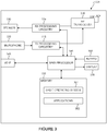
- FIGURE 3 illustrates a subscriber station according to embodiments of the present disclosure.
- the embodiment of subscribe station, such as UE 116, illustrated in FIGURE 3 is for illustration only. Other embodiments of the wireless subscriber station could be used without departing from the scope of this disclosure.
- UE 116 comprises antenna 305, radio frequency (RF) transceiver 310, transmit (TX) processing circuitry 315, microphone 320, and receive (RX) processing circuitry 325.
- SS 116 also comprises speaker 330, main processor 340, input/output (I/O) interface (IF) 345, keypad 350, display 355, and memory 360.
- Memory 360 further comprises basic operating system (OS) program 361 and a plurality of applications 362.
- the plurality of applications can include one or more of resource mapping tables (Tables 1-10 described in further detail herein below).
- Radio frequency (RF) transceiver 310 receives from antenna 305 an incoming RF signal transmitted by a base station of wireless network 100. Radio frequency (RF) transceiver 310 down-converts the incoming RF signal to produce an intermediate frequency (IF) or a baseband signal. The IF or baseband signal is sent to receiver (RX) processing circuitry 325 that produces a processed baseband signal by filtering, decoding, and/or digitizing the baseband or IF signal. Receiver (RX) processing circuitry 325 transmits the processed baseband signal to speaker 330 (i.e., voice data) or to main processor 340 for further processing (e.g., web browsing).
- IF intermediate frequency
- RX receiver
- Receiver (RX) processing circuitry 325 transmits the processed baseband signal to speaker 330 (i.e., voice data) or to main processor 340 for further processing (e.g., web browsing).
- Transmitter (TX) processing circuitry 315 receives analog or digital voice data from microphone 320 or other outgoing baseband data (e.g., web data, e-mail, interactive video game data) from main processor 340. Transmitter (TX) processing circuitry 315 encodes, multiplexes, and/or digitizes the outgoing baseband data to produce a processed baseband or IF signal. Radio frequency (RF) transceiver 310 receives the outgoing processed baseband or IF signal from transmitter (TX) processing circuitry 315. Radio frequency (RF) transceiver 310 up-converts the baseband or IF signal to a radio frequency (RF) signal that is transmitted via antenna 305.
- RF radio frequency
- main processor 340 is a microprocessor or microcontroller.
- Memory 360 is coupled to main processor 340.
- part of memory 360 comprises a random access memory (RAM) and another part of memory 360 comprises a Flash memory, which acts as a read-only memory (ROM).
- RAM random access memory
- ROM read-only memory
- Main processor 340 executes basic operating system (OS) program 361 stored in memory 360 in order to control the overall operation of wireless subscriber station 116. In one such operation, main processor 340 controls the reception of forward channel signals and the transmission of reverse channel signals by radio frequency (RF) transceiver 310, receiver (RX) processing circuitry 325, and transmitter (TX) processing circuitry 315, in accordance with well-known principles.
- OS basic operating system
- Main processor 340 is capable of executing other processes and programs resident in memory 360, such as operations for pilot scrambling for enhanced physical downlink control channels described in embodiments of the present disclosure. Main processor 340 can move data into or out of memory 360, as required by an executing process.
- the main processor 340 is configured to execute a plurality of applications 362, such as applications for CoMP communications and MU-MIMO communications.
- the main processor 340 can operate the plurality of applications 362 based on OS program 361 or in response to a signal received from BS 102.
- Main processor 340 is also coupled to I/O interface 345.
- I/O interface 345 provides subscriber station 116 with the ability to connect to other devices such as laptop computers and handheld computers. I/O interface 345 is the communication path between these accessories and main controller 340.
- Main processor 340 is also coupled to keypad 350 and display unit 355.
- the operator of subscriber station 116 uses keypad 350 to enter data into subscriber station 116.
- Display 355 may be a liquid crystal display capable of rendering text and/or at least limited graphics from web sites. Alternate embodiments may use other types of displays.
- FIGURE 4 illustrates an enhanced physical downlink control channel (e-PDCCH) according to embodiments of the present disclosure.
- e-PDCCH enhanced physical downlink control channel
- a subframe 405 includes a physical downlink shared channel (PDSCH) 410 and a physical downlink control channel (PDCCH) 415.
- PDSCH physical downlink shared channel
- PDCCH physical downlink control channel
- a number of e-PDCCH resources 400 are included in the PDSCH 410 region.
- the e-PDCCH resources 400 is included in the PDSCH 410 region for increasing DL control capacity within a cell and for mitigating inter-cell interference for DL control.
- the e-PDCCH resources 400 convey DL control signaling to Rel-11 UEs 300 configured to receive e-PDCCH.
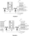
- FIGURE 5 illustrates downlink transmissions in a heterogeneous network according to embodiments of the present disclosure.
- the embodiment of the downlink transmissions 500 shown in FIGURE 5 is for illustration only. Other embodiments could be used without departing from the scope of this disclosure.
- an LTE-A Rel-11 coordinated multi-point (CoMP) transmission/reception (a CoMP scenario commonly referred to "CoMP scenario 4") includes a central controller that controls a number of transmission points (TPs) such as a macro 505 and remote radio heads (RRHs) 510, 515 in the macro coverage 520, and one physical cell ID N ID cell is assigned to the macro and RRHs.
- TPs transmission points
- RRHs remote radio heads
- N ID cell is assigned to the macro and RRHs.
- LTE specifications 3GPP LTE Rel-10
- UE-RS UE-specific demodulation reference signals
- FIGURE 5 illustrates downlink transmissions in subframes n and n+1 in a heterogeneous network.
- UEO 521 is a Rel-10 UE, while all the other UEs, UE1 522, UE2 523, UE3 524, UE4 525 and UE5 526 are Rel-11 UEs.
- the following transmissions are happening in subframe n.
- the network schedules the same PRBs for UE4 525 and UE5 526, where UE4 525 is positioned close to RRH1 510 and UE5 526 is positioned close to RRH2 515, which is far-away positioned from RRH1 510, in a subframe without worrying too much about the interference power. Furthermore, two UE-RS from RRH1 510 and RRH2 515 are not coherent combined at the receivers, with the aid of different UE-RS scrambling (initialization).
- the network MU-MIMO multiplexes and assigns orthogonal UE-RS for Rel-11 UE1 522 and Rel-10 UE0 521, without affecting Rel-10 UE0's 521 demodulation performance.
- UE1 522 and UE2 523 do not receive transmissions, e.g., because they completed data reception. Because of the UE population change, the following transmissions are happening in subframe n+1.
- the network schedules the same PRBs for UE4 525 and UE5 526, where UE4 525 is positioned close to RRH1 510 and UE5 526 positioned close to RRH2 515 which is far-away positioned from RRH1 510, in a subframe without worrying too much about the interference power. Furthermore, two UE-RS from RRH1 510 and RRH2 515 are not coherent combined at the receivers, with the aid of different UE-RS scrambling (initialization).
- the network MU-MIMO multiplexes and assigns orthogonal UE-RS for Rel-11 UE3 524 and Rel-10 UE0 521, without affecting Rel-10 UE0's demodulation performance.
- the pseudo-random sequence c(i) is defined in Section 7.2.
- N SCID The value of N SCID is zero unless specified otherwise.
- n SCID is given by the DCI format 2B or 2C associated with the PDSCH transmission.
- n SCID is indicated by the scrambling identity field according to Table 6.10.3,1-1.
- n SCID is given by Table 5.3.3.1.5C-1 in REF3.
- Table 6.10.3.1-1 Mapping of scrambling identity field in DCI format 2B to n SCID values for antenna ports 7 and 8. Scrambling identity field in DCI format 2B n SCID 0 0 1 1
- the demodulation reference signal associated with e-PDCCH is the demodulation reference signal associated with e-PDCCH.
- a demodulation reference signal associated with e-PDCCH is not transmitted in resource elements (k,l) in which one of the physical channels or physical signals other than the demodulation reference signals defined in 6.1 are transmitted using resource elements with the same index pair (k,l) regardless of their antenna port p .
- the pseudo-random sequence c(i) is defined in Section 7.2.
- the sequence w p (i) is given by Table 6.10.3A.2-1.
- the sequence w p (i) is given by Table 6.10.3A.2-2.
- Table 6.10.3A.2-2 The sequence w p (i) for extended cyclic prefix.
- demodulation reference signals are not supported on antenna ports 109 to 110.
- Replacing antenna port numbers 7 - 10 by 107 - 110 provides an illustration of the resource elements used for demodulation reference signals associated with e-PDCCH for normal cyclic prefix.
- Replacing antenna port numbers 7 - 8 by 107 - 108 provides an illustration of the resource elements used for demodulation reference signals associated with e-PDCCH for extended cyclic prefix.
- an e-PDCCH set is defined as a group of N PRB pairs
- K ⁇ 1 e-PDCCH sets are configured in a UE specific manner:
- higher layer signalling can configure a UE with one or multiple e-PDCCH-PRB-sets for e-PDCCH monitoring.
- Each e-PDCCH-PRB-set consists of set of ECCEs numbered from 0 to N ECCE,p,k -1 where N ECCE,p,k is the number of ECCEs in e-PDCCH-PRB-set p of subframe k .
- Each e-PDCCH-PRB-set can be configured for either localized e-PDCCH transmission or distributed e-PDCCH transmission.
- the UE monitors a set of e-PDCCH candidates on one or more activated serving cells as configured by higher layer signalling for control information. Monitoring implies attempting to decode each of the e-PDCCHs in the set according to the monitored DCI formats.
- the set of e-PDCCH candidates to monitor are defined in terms of e-PDCCH UE-specific search spaces.
- the subframes in which the UE monitors e-PDCCH UE-specific search spaces are configured by higher layers.
- the UE is not expected to monitor e-PDCCH in special subframes for the special subframe configurations 0 and 5 shown in Table 4.2-1 of REF3.
- the UE is not expected to monitor e-PDCCH in special subframes for the special subframe configurations 0, 4 and 7 shown in Table 4.2-1 of REF3.
- a UE is not expected to monitor an e-PDCCH candidate, if an ECCE corresponding to that e-PDCCH candidate is mapped to a PRB pair that overlaps in frequency with a transmission of either PBCH or primary or secondary synchronisation signals in the same subframe.
- a port (Port A) is considered to be quasi co-located with another port (Port B) if the UE is allowed to derive the "large scale properties" of Port A, e.g. needed for channel estimation/time-frequency synchronization based on Port A, from measurement on Port B.
- the large scale channel properties are for e.g.: Delay spread; Doppler spread; Frequency shift; Average received power (may only be needed between ports of the same type); and Received Timing.
- Another alternative definition of quasi co-location of antenna ports is as follows: "If two antenna ports are 'quasi co-located', the UE may assume that large-scale properties of the channel over which a symbol on one antenna port is conveyed can be inferred from the channel over which a symbol on the other antenna port is conveyed".
- the "large-scale properties" mentioned in the above definition consist of some or all of: Delay spread; Doppler spread; Doppler shift; Average gain; and Average delay.
- the term channel in the above definition includes all the effects and transformations occurring after the corresponding antenna port as defined in TS 36.211, including impairments and non-idealities of the radio equipment from eNB; antenna ports can be assumed to be ideally synchronized in time and frequency; non-idealities in the RF chain as well as network's intended control of tx delay, tx frequency shift and tx power difference of the transmit signal as compared to the nominal value are included in the channel model.
- a UE can be configured with one or more NZP CSI-RS resources e.g. as follows:
- the network is configured to efficiently support these diverse and dynamically changing transmission schemes.
- a control signaling design is utilized for advanced (or Rel-11) UEs.
- FIGURE 6 illustrates an e-PDCCH downlink modulated reference signal (DMRS) scrambling method according to embodiments of the present disclosure.
- DMRS downlink modulated reference signal
- DM-RS demodulation reference signals
- Embodiments of the present disclosure illustrate methods of configuring DMRS scrambling initializations in e-PDCCH physical resource blocks (PRBs) in an e-PDCCH search space.
- PRBs physical resource blocks
- UE 116 obtains n SCID value for the DMRS channel estimation, according to one of the following alternatives.
- UE 116 obtains (X,Y) for the DMRS channel estimation, according to one of the following alternatives:
- a first DMRS scrambling alternative 605 (referenced as Alt 1): (Common (X,Y)), in all the e-PDCCH PRBs 630 in the search space 600, the scrambling initialization value is generated according to a single pair of (X,Y).
- UE 116 only needs to know the single pair of (X,Y) for DMRS channel estimation.
- the single pair of (X,Y) can be RRC configured.
- a second DMRS scrambling alternative 610 (referenced as Alt 2): (Multiple hypothesis on (X,Y)), in all the e-PDCCH PRBs 630 in the search space 600, the scrambling initialization value is generated according to one of N pairs of (X,Y), where N is an integer > 1.
- N is an integer > 1.
- a subset of the N pairs of (X,Y) is signaled to each UE, so that the UE can try each of the pairs of (X, Y) in the subset for DMRS channel estimation and e-PDCCH demodulation.
- the second DMRS scrambling alternative 610 illustrates the case where UE 116 is instructed to use two candidate pairs of (X,Y) for e-PDCCH DMRS channel estimation, in which case, UE 116 tries to estimate the channels (and demodulate e-PDCCH) according to each of the two hypothesis of (X,Y).
- the multiple pairs of (X,Y) can be RRC configured.
- a third DMRS scrambling alternative 615 (referenced as Alt 3): (Varying (X,Y)'s across PRBs), the scrambling initialization values may change over different e-PDCCH PRBs in the search space 600.
- UE 116 is informed (e.g., RRC configured) of a scrambling initialization mapping pattern across the e-PDCCH PRBs in the search space 600, and uses the mapping pattern for DMRS channel estimation and e-PDCCH demodulation.
- UE 116 is implicitly signaled of the DMRS scrambling initialization for a data channel, i.e., a PDSCH/PUSCH by means of a DMRS scrambling initialization used for the e-PDCCH DL/UL grant scheduling the PDSCH/PUSCH. That is, when UE 116 detects a DL/UL grant from an e-PDCCH whose DMRS scrambling initialization is (X,Y), then the same (X,Y) are used for DMRS scrambling for the PDSCH/PUSCH scheduled by the DL/UL grant.
- FIGURE 7 illustrates example e-PDCCH transmissions according to Method 2, Alt 2.
- the embodiment of the e-PDCCH transmissions 700 shown in FIGURE 7 is for illustration only. Other embodiments could be used without departing from the scope of this disclosure.
- FIGURE 7 In the example shown in FIGURE 7 , three example e-PDCCH transmissions from one of the two transmission points (TPs) 705, 710 are illustrated.
- an e-PDCCH (or a DCI) for UE 116 is transmitted across two PRBs, where the two PRBs' DMRS are scrambled according to (X1, Y1) 720, and transmitted from TP1 705.
- an e-PDCCH (or a DCI) for UE 116 is transmitted across four PRBs, where the four PRBs' DMRS are scrambled according to (X2, Y2) 725, and transmitted from TP2 710.
- an e-PDCCH (or a DCI) for UE 116 is transmitted across four PRBs, where the four PRBs' DMRS are scrambled according to (X1, Y1) 720, and transmitted from TP1 705.
- the number of PRBs used for transmitting an e-PDCCH can be any integer, and the numbers of PRBs used in the examples are just for illustration.
- multiple e-PDCCHs can be multiplexed in the same set of PRBs.
- the two PRBs carrying e-PDCCH for UE1 116 in Ex1 may also carry another e-PDCCH for another UE, e.g., UE2 (such as UE 115 shown on FIGURE 1 ); the two e-PDCCHs are multiplexed, such as by one of: TDM, FDM, TDM/FDM and CDM.
- the eNodeB can perform dynamic TP selection for e-PDCCH transmissions.
- TP1 705 and TP2 710 are controlled by a common central scheduler 715, which determines which TP to transmit an e-PDCCH to individual UEs. For example, when the channel between TP1 705 and UE 116 is stronger than TP2 710 and UE 116, eNodeB central controller 715 can decide to transmit e-PDCCH through the link between TP1 705 and UE 116 (according to Ex1 or Ex2).
- FIGURE 8 illustrates example e-PDCCH transmissions according to Method 2, Alt 3.
- the embodiment of the e-PDCCH transmissions 800 shown in FIGURE 8 is for illustration only. Other embodiments could be used without departing from the scope of this disclosure.
- FIGURE 8 an example of e-PDCCH transmissions according to Alt 3 is illustrated.
- an example e-PDCCH search space 805 and the scrambling initialization pattern 810 are shown.
- the right side of FIGURE 8 shows three example e-PDCCH transmissions from at least one of the two transmission points (TPs) 815, 820.
- an e-PDCCH (or a DCI) for UE 116 is transmitted across four PRBs, where two PRBs' DMRS are scrambled according to (X1, Y1) 825 and the other two PRBs' DMRS are scrambled according to (X2, Y2) 830.
- the PRBs scrambled according to (X1, Y1) 825 are transmitted from TP1 815
- the PRBs scrambled according to (X2, Y2) 830 are transmitted from TP2 820.
- all the four PRBs are transmitted from one TP, i.e., either from TP1 815 or TP2 820.
- an ePDCCH for UE 116 is transmitted across two PRBs, where the two PRBs are scrambled according to (X2, Y2) 830.
- the two PRBs are transmitted from either TP1 815 or TP2 820.
- an e-PDCCH for UE 116 is transmitted across two PRBs, where the two PRBs are scrambled according to (X1, Y1) 825 and transmitted from TP1 815.
- the two PRBs are transmitted from either TP1 815 or TP2 820.
- e-PDCCH DMRS scrambling initialization is PRB-specifically performed according to the scrambling initialization pattern.
- the eNodeB can perform dynamic TP selection for e-PDCCH transmissions. For example, when the channel between TP1 815 and UE 116 is stronger than TP2 820 and UE 116, eNodeB central scheduler 825 can decide to transmit e-PDCCH through the link between TP1 815 and UE 116 (according to Ex3).
- Ex1 is essentially a spatial diversity transmission, which can help UE 116 to reliably receive the e-PDCCH even if no good CSIs are available (e.g., due to medium to high mobility).
- Certain embodiments illustrate methods to efficiently utilize the e-PDCCH resources by allowing the MU-MIMO and/or the CoMP DPS for e-PDCCH.
- e-PDCCH DMRS configuration parameter(s) are independently configurable for each e-PDCCH PRB set.
- RRC radio resource control
- n ID DMRS , i is the i-th virtual cell ID associated with scrambling ID i, configured in the higher layer for PDSCH UE-RS.
- FIGURE 9 illustrates another e-PDCCH downlink modulated reference signal (DMRS) scrambling method according to embodiments of the present disclosure.
- DMRS downlink modulated reference signal
- Each set of the e-PDCCH PRBs are configured with different e-PDCCH DMRS configuration parameters; the first e-PDCCH set 905 is configured with (X1, Y1) 910 and the second e-PDCCH set 915 is configured with (X2, Y2) 920.
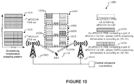
- FIGURE 10 illustrates an example of e-PDCCH transmissions according to method 2, alternative 3 or method 3.
- the embodiment of the e-PDCCH transmissions 1000 shown in FIGURE 10 is for illustration only. Other embodiments could be used without departing from the scope of this disclosure.
- the scrambling initialization pattern is constructed such that a first group of consecutive PRBs is assigned with a first scrambling initialization, and a second group of consecutive PRBs is assigned with a second scrambling initialization.
- the right hand side of FIGURE 10 shows three example e-PDCCH transmissions from at least one of the two transmission points (TPs) 1005, 1010.
- the scrambling initialization pattern is constructed such that a first set of e-PDCCH PRBs 1015 is assigned with a first scrambling initialization 1020, and a second set of e-PDCCH PRBs 1025 is assigned with a second scrambling initialization 1030.
- the right hand side of FIGURE 10 shows three example e-PDCCH transmissions from at least one of the two transmission points (TPs), 1005, 1010.
- TPs transmission points
- a first DCI 1040 is transmitted from TP1 1005 with the first DMRS scrambling initialization 1020
- a second DCI is transmitted from TP2 1010 with the second DMRS scrambling initialization 1030.
- At least one DCI is transmitted from TP2 1010, each with the second DMRS scrambling initialization 1030.
- at least one DCI is transmitted form TP1 1005, each with the first DMRS scrambling initialization 1020.
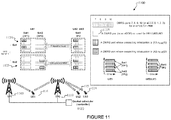
- FIGURE 11 illustrates e-PDCCH transmissions to a coordinated multipoint (COMP) UE according to embodiments of the present disclosure.
- the embodiment of the e-PDCCH transmissions shown in FIGURE 11 is for illustration only. Other embodiments could be used without departing from the scope of this disclosure.
- the EPDCCH transmissions are to a CoMP UE, i.e., UE 116 placed at similar distances from TP1 1105 and TP2 1110, and non-CoMP UEs, i.e., UE 115 and UE 114, which are close to TP2 1110.
- the e-PDCCH PRBs 1115 not containing e-PDCCH for UE 116/UE 115/UE 114 can be used for transmitting e-PDCCH to other UEs.
- an e-PDCCH for UE 116 is transmitted across two PRBs, where the two PRBs are scrambled according to (X2,Y2) and transmitted from TP1 1105 as a result of dynamic point selection (DPS).
- the two PRBs are transmitted from TP1 1105, which is the better TP for the e-PDCCH reception.
- UE 115 and UE 114 near TP2 1110 can receive e-PDCCH in the same time-frequency resource with a differently scrambled DMRS for spatial reuse.
- an e-PDCCH for UE 116 is transmitted across two PRBs, where the two PRBs are scrambled according to (X1, Y1).
- the two PRBs are transmitted from TP2 1110, which is the better TP for the e-PDCCH reception.
- UE 115 and UE 114 near TP2 1110 can receive e-PDCCH in the same PRB with different DMRS ports for orthogonal DMRS multiplexing.
- e-PDCCH DMRS configuration parameter(s) n ID EPDCCH k , n SCID EPDCCH k are independently configurable for each e-PDCCH PRB set for the localized e-PDCCH transmissions, while a common DMRS configuration parameter(s) are configured for all the e-PDCCH PRB sets for the distributed ePDCCH transmissions.
- K K L + K D is the total number of the e-PDCCH PRB sets
- K L is the total number of configured PRB sets for localized transmissions
- K D is the total number of configured PRB sets for distributed transmissions.
- Two alternatives can be utilized to configure the K L pairs of e-PDCCH DMRS parameters for localized transmission:
- a first alternative (Alt 1) The K L pairs of e-PDCCH DMRS parameters are independently RRC configured. Independently configuring the K L has an advantage of being fully flexible in choosing the e-PDCCH DMRS parameters.
- the PDSCH UE-RS scrambling ID configured for set k is i
- n ID DMRS , i is the i-th virtual cell ID associated with scrambling ID i, configured in the higher layer for PDSCH UE-RS.
- This alternative (Alt 2) has an advantage of reducing RRC signaling overhead.
- a first alternative (Alt 1) The one common pair of the e-PDCCH DMRS parameters is RRC configured, independently from the K L pairs of e-PDCCH DMRS parameters.
- This alternative (Alt 1) has an advantage of being fully flexible in choosing the e-PDCCH DMRS parameters.
- PCID physical cell ID
- This alternative (Alt 2) does not require any RRC signaling, and hence completely eliminates the RRC overhead.
- a third alternative (Alt 3) : The one common pair of e-PDCCH DMRS parameters for distributed transmission is set according to one of the virtual cell IDs configured for PDSCH UE-RS.
- a PDSCH UE-RS scrambling ID is configured for the one pair of the e-PDCCH DMRS.
- n ID DMRS , i is the i-th virtual cell ID associated with scrambling ID i, configured in the higher layer for PDSCH UE-RS.
- Configuring the PDSCH UE-RS scrambling ID for the one pair of the e-PDCCH DMRS has an advantage of reducing RRC signaling overhead.
- n ID EPDCCH k n SCID EPDCCH k are configured, one for the localized e-PDCCH transmissions and the other for the distributed e-PDCCH transmissions.
- UE 116 is configured to assume a quasi co-location of DM-RS ports for e-PDCCH according to specified conditions.
- UE 116 does not assume that the DM-RS ports for e-PDCCH are quasi co-located across e-PDCCH sets. UE 116 can assume that DM-RS ports for e-PDCCH within an e-PDCCH set are quasi co-located. This is because different e-PDCCH set may be transmitted by different transmission points.
- UE 116 does not assume that the DM-RS ports for e-PDCCH are quasi co-located if e-PDCCH DM-RS scrambling IDs are not the same.
- the DM-RS ports for e-PDCCH with the same e-PDCCH DM-RS scrambling IDs may be assumed by UE 116 to be quasi co-located. This is because DM-RS scrambling IDs are typically different for different transmission points.
- UE 116 does not assume that the DM-RS ports across e-PDCCH sets are quasi co-located.
- UE 116 does not assume that the DM-RS ports across localized e-PDCCH sets with different e-PDCCH DM-RS scrambling IDs are quasi co-located.
- the DM-RS ports across localized e-PDCCH sets with the same e-PDCCH DM-RS scrambling IDs can be assumed by UE 116 to be quasi co-located.
- the DM-RS ports across distributed e-PDCCH sets can be assumed by UE 116 to be quasi co-located (since the DM-RS ports share the same e-PDCCH DM-RS scrambling IDs).
- UE 116 does not assume that the DM-RS ports between localized e-PDCCH and distributed e-PDCCH are quasi co-located if the e-PDCCH DM-RS scrambling IDs for localized e-PDCCH and distributed e-PDCCH are different.
- the DM-RS ports between localized e-PDCCH and distributed e-PDCCH can be assumed by the UE to be quasi co-located if the e-PDCCH DM-RS scrambling IDs for localized e-PDCCH and distributed e-PDCCH are the same. This further improves e-PDCCH DM-RS channel estimation.
- UE 116 does not assume that the DM-RS ports between localized e-PDCCH and distributed e-PDCCH are quasi co-located regardless of whether the DM-RS scrambling IDs are the same or not. This is because transmission points for localized e-PDCCH and distributed e-PDCCH are generally not the same.
- UE 116 does not assume that the DM-RS ports between localized e-PDCCH and distributed e-PDCCH are quasi co-located if the e-PDCCH DM-RS scrambling IDs for localized e-PDCCH and distributed e-PDCCH are different.
- the DM-RS ports across localized e-PDCCH sets can be assumed by UE 116 to be quasi co-located.
- the DM-RS ports across distributed e-PDCCH sets can be assumed by UE 116 to be quasi co-located.
- the DM-RS ports for e-PDCCH have the same DM-RS scrambling ID as that of DM-RS ports for PDSCH
- the DM-RS ports for e-PDCCH and the DM-RS ports for PDSCH can be assumed by UE 116 to be quasi co-located; otherwise UE 116 does not assume quasi co-location of the DM-RS ports for e-PDCCH and the DM-RS ports for PDSCH.
- UE 116 does not assume that the DM-RS ports for e-PDCCH are quasi co-located with the DM-RS ports for PDSCH regardless of DM-RS scrambling IDs.
- the network For each set of quasi co-located DM-RS ports, the network configures a reference NZP CSI-RS resource/a reference CRS resource that can be assumed to the quasi co-located with the DM-RS ports.
- PDCCH is scrambled as in the following, according to 36.211 specifications.
- e-PDCCH scrambling method is performed.
- e-PDCCH scrambling initialization is determined by a VCID X , where X replaces the physical cell ID N ID cell in the PDCCH scrambling initialization equation.
- a single (or common) X is used for e-PDCCH scrambling in all the e-PDCCH sets configured for UE 116.
- X is configured independently of the VCID configured for e-PDCCH DMRS. In another example, X is the same as the VCID configured for e-PDCCH DMRS, which is also commonly used for all the e-PDCCH sets.
- the eNodeB uses set-specific X's for e-PDCCH scrambling in the e-PDCCH sets configured for UE 116 (i.e., for e-PDCCH scrambling, a first X value is used for a first e-PDCCH set; and a second X value is used for a second e-PDCCH set).
- the eNodeB (e.g., BS 102) configures X's independently of the VCIDs configured for e-PDCCH DMRS.
- the eNodeB uses the same X for ePDCCH scrambling in an e-PDCCH set as the VCID configured for e-PDCCH DMRS in the same e-PDCCH set (i.e., for an e-PDCCH set, a common VCID is configured for e-PDCCH scrambling and e-PDCCH DMRS scrambling). That is, the X used for ePDCCH scrambling in an e-PDCCH set is the same as the VCID configured for e-PDCCH DMRS in the same e-PDCCH set.
- Method 4 in embodiment 1 is used for e-PDCCH DMRS configuration
- the K L VCIDs are used for e-PDCCH scrambling as well as e-PDCCH DMRS scrambling in the respective e-PDCCH sets for localized transmissions
- the one VCID configured for distributed transmissions is used for e-PDCCH scrambling as well as e-PDCCH DMRS scrambling for distributed transmissions.
- Method 5 in embodiment 1 is used for e-PDCCH DMRS configuration
- the one VCID is used for e-PDCCH scrambling as well as e-PDCCH DMRS scrambling for localized transmissions
- the one VCID configured for distributed transmissions is used for e-PDCCH scrambling as well as e-PDCCH DMRS scrambling for distributed transmissions.
- e-PDCCH scrambling initialization is determined by a VCID X, as well as the UE-ID or RNTI number, n RNTI .
- the scrambling initialization for e-PDCCH scrambling is determined UE-specifically.
- c init n RNTI ⁇ 2 14 + ⁇ n s /2 ⁇ 2 9 +X and n RNTI is C-RNTI.
- c init n RNTI ⁇ 2 14 + ⁇ n s /2 ⁇ 2 9 +X and n RNTI is SPS C-RNTI.
- the eNodeB (e.g., BS 102) configures X in a same way as listed in Method 1 (Embodiment 3, method 1), of the current embodiment.
- the scrambling initialization ensures to achieve area splitting for e-PDCCH transmissions in CoMP scenario 4.
- the false alarm probability of UE-specific scrambling initialization is smaller than that of cell-specific initialization.
- the false alarm is defined as an event that a first UE assigned with a first RNTI obtains a CRC check for a PDCCH sent for a second UE assigned with a second RNTI.
- CRC of the PDCCH sent for each UE is scrambled with its respective RNTI.
- the first UE will obtain a false CRC check for the PDCCH sent for the second UE, when the CRC bits in the A bit-locations are flipped by the channel noise, and the non-CRC part of the PDCCH does not play any role to reduce the false alarm probability.
- the non-CRC part of the e-PDCCH of the first UE will be different from that of the second UE as well as the CRC part of the e-PDCCH, which will help to reduce false alarm probability.
- Embodiment 3 In another method (Embodiment 3, method 3), distributed ePDCCH scrambling initialization is determined by Method 1 (Embodiment 3, method 1) in the current embodiment, and localized ePDCCH scrambling initialization is determined by Method 2 (Embodiment 3, method 2) in the current embodiment.
Landscapes
- Engineering & Computer Science (AREA)
- Computer Networks & Wireless Communication (AREA)
- Signal Processing (AREA)
- Computer Security & Cryptography (AREA)
- Mobile Radio Communication Systems (AREA)
Description
- The present application relates generally to wireless communications and, more specifically, to a system and method for pilot signal scrambling for enhanced physical control channels.
- In 3GPP Long Term Evolution (LTE) (3GPP LTE Rel-10), regardless of which transmission point (TP) a user equipment (UE) receives downlink (DL) data signals from, the UE would expect that UE-specific demodulation reference signals (UE-RS) are scrambled according to the physical cell ID

- ETRI, "DM RS sequence setting for downlink CoMP", 3GPP DRAFT; R1-113957 DL DM RS SEQUENCE, 3RD GENERATION PARTNERSHIP PROJECT (3GPP), discloses for the initialization of the DM RS sequence generator, an option of reusing the Rel-10 initialization formula, but with UE-specific virtual Cell ID (VCI) denoted

- "DL DM-RS sequence for Rel-11 CoMP", 3GPP DRAFT; R1-114074 COMP DMRS, 3RD GENERATION PARTNERSHIP PROJECT (3GPP), discloses for DM-RS use of the same DMRS sequence generator as in Rel-10; a UE can be semi-statically configured in a UE specific manner, where initialization values for DMRS scrambling generator are available for dynamic selection. Initialization values can be configured to correspond to Rel-10 DMRS. The pseudo-random sequence c(i) is initialized with

- It is the object of the present invention to provide improved methods and systems for scrambling in enhanced physical downlink control channels.
- This object is achieved by the subject-matter of the independent claims.
- Embodiments are defined by the dependent claims.
- A base station configured to communicate with a plurality of base stations via a backhaul link and configured to communicate with a plurality of user equipments is provided. The base station includes a transmit path configured to transmit data, reference signals, synchronization signals and control elements to at least one of the plurality of subscriber stations. The base station also includes processing circuitry configured to configure enhanced physical downlink control channel (e-PDCCH) DMRS parameters for each of a plurality of e-PDCCH sets.
- A method for mapping synchronization signals is provided. The method includes transmitting data, reference signals, synchronization signals and control elements to at least one of the plurality of subscriber stations. The method also includes configuring enhanced physical downlink control channel (e-PDCCH) DMRS parameters for each of a plurality of e-PDCCH sets.
- A subscriber station configured to communicate with at least one base station, which is configured to communicate with a plurality of base stations via a backhaul link, is provided. The subscriber station includes receiver configured to receive data, reference signals, synchronization signals and control elements from the base station. The subscriber station also includes processing circuitry configured to read physical resource blocks (PRBs) containing enhanced physical downlink control channel (e-PDCCH) downlink modulated reference signals (DMRS) parameters that have been configured for each of a plurality of e-PDCCH sets.
- Before undertaking the DETAILED DESCRIPTION below, it may be advantageous to set forth definitions of certain words and phrases used throughout this patent document: the terms "include" and "comprise," as well as derivatives thereof, mean inclusion without limitation; the term "or," is inclusive, meaning and/or; the phrases "associated with" and "associated therewith," as well as derivatives thereof, may mean to include, be included within, interconnect with, contain, be contained within, connect to or with, couple to or with, be communicable with, cooperate with, interleave, juxtapose, be proximate to, be bound to or with, have, have a property of, or the like; and the term "controller" means any device, system or part thereof that controls at least one operation, such a device may be implemented in hardware, firmware or software, or some combination of at least two of the same. It should be noted that the functionality associated with any particular controller may be centralized or distributed, whether locally or remotely. Definitions for certain words and phrases are provided throughout this patent document, those of ordinary skill in the art should understand that in many, if not most instances, such definitions apply to prior, as well as future uses of such defined words and phrases.
- For a more complete understanding of the present disclosure and its advantages, reference is now made to the following description taken in conjunction with the accompanying drawings, in which like reference numerals represent like parts:
-
FIGURE 1 illustrates a wireless network according to an embodiment of the present disclosure; -
FIGURE 2A illustrates a high-level diagram of a wireless transmit path according to an embodiment of this disclosure; -
FIGURE 2B illustrates a high-level diagram of a wireless receive path according to an embodiment of this disclosure; -
FIGURE 3 illustrates a subscriber station according to an exemplary embodiment of the disclosure; -
FIGURE 4 illustrates an enhanced physical downlink control channel (e-PDCCH) according to embodiments of the present disclosure; -
FIGURE 5 illustrates downlink transmissions in a heterogeneous network according to embodiments of the present disclosure; -
FIGURE 6 illustrates an e-PDCCH downlink modulated reference signal (DMRS) scrambling method according to embodiments of the present disclosure; -
FIGURE 7 illustrates example e-PDCCH transmissions according to embodiments of the present disclosure; -
FIGURE 8 illustrates example e-PDCCH transmissions according to embodiments of the present disclosure; -
FIGURE 9 illustrates another e-PDCCH downlink modulated reference signal (DMRS) scrambling method according to embodiments of the present disclosure; -
FIGURE 10 illustrates an example of e-PDCCH transmissions according to embodiments of the present disclosure; and -
FIGURE 11 illustrates e-PDCCH transmissions to a coordinated multipoint (COMP) UE according to embodiments of the present disclosure. -
FIGURES 1 through 11 , discussed below, and the various embodiments used to describe the principles of the present disclosure in this patent document are by way of illustration only and should not be construed in any way to limit the scope of the disclosure. Those skilled in the art will understand that the principles of the present disclosure may be implemented in any suitably arranged wireless communication system. - The following documents and standards descriptions are referenced
(i) 3GPP Technical Specification No. 36.211, version 10.1.0, "E-UTRA, Physical Channels and Modulation" (hereinafter "REF1"); (ii) 3GPP Technical Specification No. 36.212, version 10.1.0, "E-UTRA, Multiplexing and Channel Coding" (hereinafter "REF2"); (iii) 3GPP Technical Specification No. 36.213, version 10.1.0, "E-UTRA, Physical Layer Procedures" (hereinafter "REF3"); and (iv) 3GPP Technical Specification No. 36.331, version 10.1.0 (hereinafter "REF4") . -
FIGURE 1 illustrates awireless network 100 according to one embodiment of the present disclosure. The embodiment ofwireless network 100 illustrated inFIGURE 1 is for illustration only. Other embodiments ofwireless network 100 could be used without departing from the scope of this disclosure. - The
wireless network 100 includes eNodeB (eNB) 101, eNB 102, and eNB 103. The eNB 101 communicates with eNB 102 and eNB 103. The eNB 101 also communicates with Internet protocol (IP)network 130, such as the Internet, a proprietary IP network, or other data network. - Depending on the network type, other well-known terms may be used instead of "eNodeB," such as "base station" or "access point". For the sake of convenience, the term "eNodeB" shall be used herein to refer to the network infrastructure components that provide wireless access to remote terminals. In addition, the term user equipment (UE) is used herein to refer to remote terminals that can be used by a consumer to access services via the wireless communications network. Other well know terms for the remote terminals include "mobile stations" and "subscriber stations."
- The eNB 102 provides wireless broadband access to
network 130 to a first plurality of user equipments (UEs) withincoverage area 120 of eNB 102. The first plurality of UEs includes UE 111, which may be located in a small business; UE 112, which may be located in an enterprise; UE 113, which may be located in a WiFi hotspot; UE 114, which may be located in a first residence; UE 115, which may be located in a second residence; and UE 116, which may be a mobile device, such as a cell phone, a wireless laptop, a wireless PDA, or the like. UEs 111-116 may be any wireless communication, device, such as, but not limited to, a mobile phone, mobile PDA and any mobile station (MS). - For the sake of convenience, the term "user equipment" or "UE" is used herein to designate any remote wireless equipment that wirelessly accesses an eNB, whether the UE is a mobile device (e.g., cell phone) or is normally considered a stationary device (e.g., desktop personal computer, vending machine, etc.). In other systems, other well-known terms may be used instead of "user equipment", such as "mobile station" (MS), "subscriber station" (SS), "remote terminal" (RT), "wireless terminal" (WT), and the like.
- The eNB 103 provides wireless broadband access to a second plurality of UEs within
coverage area 125 of eNB 103. The second plurality of UEs includes UE 115 and UE 116. In some embodiment, one or more of eNBs 101-103 may communicate with each other and with UEs 111-116 using LTE or LTE-A techniques including techniques for: pilot scrambling for enhanced physical downlink control channels (e.g., e-PDCCH scrambling) described in embodiments of the present disclosure. - Dotted lines show the approximate extents of
coverage areas coverage areas - Although
FIGURE 1 depicts one example of awireless network 100, various changes may be made toFIGURE 1 . For example, another type of data network, such as a wired network, may be substituted forwireless network 100. In a wired network, network terminals may replace eNBs 101-103 and UEs 111-116. Wired connections may replace the wireless connections depicted inFIGURE 1 . -
FIGURE 2A is a high-level diagram of a wireless transmit path.FIGURE 2B is a high-level diagram of a wireless receive path. InFIGURES 2A and 2B , the transmitpath 200 may be implemented, e.g., ineNB 102 and the receivepath 250 may be implemented, e.g., in a UE, such asUE 116 ofFIGURE 1 . It will be understood, however, that the receivepath 250 could be implemented in an eNB (e.g. eNB 102 ofFIGURE 1 ) and the transmitpath 200 could be implemented in a UE. In certain embodiments, transmitpath 200 and receivepath 250 are configured to perform methods for pilot scrambling for enhanced physical downlink control channels described in embodiments of the present disclosure. - Transmit
path 200 comprises channel coding andmodulation block 205, serial-to-parallel (S-to-P) block 210, Size N Inverse Fast Fourier Transform (IFFT) block 215, parallel-to-serial (P-to-S) block 220, addcyclic prefix block 225, up-converter (UC) 230. Receivepath 250 comprises down-converter (DC) 255, removecyclic prefix block 260, serial-to-parallel (S-to-P) block 265, Size N Fast Fourier Transform (FFT) block 270, parallel-to-serial (P-to-S) block 275, channel decoding anddemodulation block 280. - At least some of the components in
FIGURES 2A and 2B may be implemented in software while other components may be implemented by configurable hardware (e.g., a processor) or a mixture of software and configurable hardware. In particular, it is noted that the FFT blocks and the IFFT blocks described in this disclosure document may be implemented as configurable software algorithms, where the value of Size N may be modified according to the implementation. - Furthermore, although this disclosure is directed to an embodiment that implements the Fast Fourier Transform and the Inverse Fast Fourier Transform, this is by way of illustration only and should not be construed to limit the scope of the disclosure. It will be appreciated that in an alternate embodiment of the disclosure, the Fast Fourier Transform functions and the Inverse Fast Fourier Transform functions may easily be replaced by Discrete Fourier Transform (DFT) functions and Inverse Discrete Fourier Transform (IDFT) functions, respectively. It will be appreciated that for DFT and IDFT functions, the value of the N variable may be any integer number (i.e., 1, 2, 3, 4, etc.), while for FFT and IFFT functions, the value of the N variable may be any integer number that is a power of two (i.e., 1, 2, 4, 8, 16, etc.).
- In transmit
path 200, channel coding andmodulation block 205 receives a set of information bits, applies coding (e.g., LDPC coding) and modulates (e.g., Quadrature Phase Shift Keying (QPSK) or Quadrature Amplitude Modulation (QAM)) the input bits to produce a sequence of frequency-domain modulation symbols. Serial-to-parallel block 210 converts (i.e., de-multiplexes) the serial modulated symbols to parallel data to produce N parallel symbol streams where N is the IFFT/FFT size used ineNB 102 andUE 116. Size N IFFT block 215 then performs an IFFT operation on the N parallel symbol streams to produce time-domain output signals. Parallel-to-serial block 220 converts (i.e., multiplexes) the parallel time-domain output symbols from Size N IFFT block 215 to produce a serial time-domain signal. Addcyclic prefix block 225 then inserts a cyclic prefix to the time-domain signal. Finally, up-converter 230 modulates (i.e., up-converts) the output of addcyclic prefix block 225 to RF frequency for transmission via a wireless channel. The signal may also be filtered at baseband before conversion to RF frequency. - The transmitted RF signal arrives at
UE 116 after passing through the wireless channel and reverse operations to those ateNB 102 are performed. Down-converter 255 down-converts the received signal to baseband frequency and removecyclic prefix block 260 removes the cyclic prefix to produce the serial time-domain baseband signal. Serial-to-parallel block 265 converts the time-domain baseband signal to parallel time domain signals. Size N FFT block 270 then performs an FFT algorithm to produce N parallel frequency-domain signals. Parallel-to-serial block 275 converts the parallel frequency-domain signals to a sequence of modulated data symbols. Channel decoding anddemodulation block 280 demodulates and then decodes the modulated symbols to recover the original input data stream. - Each of eNBs 101-103 may implement a transmit path that is analogous to transmitting in the downlink to UEs 111-116 and may implement a receive path that is analogous to receiving in the uplink from UEs 111-116. Similarly, each one of UEs 111-116 may implement a transmit path corresponding to the architecture for transmitting in the uplink to eNBs 101-103 and may implement a receive path corresponding to the architecture for receiving in the downlink from eNBs 101-103.
-
FIGURE 3 illustrates a subscriber station according to embodiments of the present disclosure. The embodiment of subscribe station, such asUE 116, illustrated inFIGURE 3 is for illustration only. Other embodiments of the wireless subscriber station could be used without departing from the scope of this disclosure. -
UE 116 comprisesantenna 305, radio frequency (RF)transceiver 310, transmit (TX)processing circuitry 315,microphone 320, and receive (RX)processing circuitry 325.SS 116 also comprisesspeaker 330,main processor 340, input/output (I/O) interface (IF) 345,keypad 350,display 355, andmemory 360.Memory 360 further comprises basic operating system (OS)program 361 and a plurality ofapplications 362. The plurality of applications can include one or more of resource mapping tables (Tables 1-10 described in further detail herein below). - Radio frequency (RF)
transceiver 310 receives fromantenna 305 an incoming RF signal transmitted by a base station ofwireless network 100. Radio frequency (RF)transceiver 310 down-converts the incoming RF signal to produce an intermediate frequency (IF) or a baseband signal. The IF or baseband signal is sent to receiver (RX)processing circuitry 325 that produces a processed baseband signal by filtering, decoding, and/or digitizing the baseband or IF signal. Receiver (RX)processing circuitry 325 transmits the processed baseband signal to speaker 330 (i.e., voice data) or tomain processor 340 for further processing (e.g., web browsing). - Transmitter (TX)
processing circuitry 315 receives analog or digital voice data frommicrophone 320 or other outgoing baseband data (e.g., web data, e-mail, interactive video game data) frommain processor 340. Transmitter (TX)processing circuitry 315 encodes, multiplexes, and/or digitizes the outgoing baseband data to produce a processed baseband or IF signal. Radio frequency (RF)transceiver 310 receives the outgoing processed baseband or IF signal from transmitter (TX)processing circuitry 315. Radio frequency (RF)transceiver 310 up-converts the baseband or IF signal to a radio frequency (RF) signal that is transmitted viaantenna 305. - In certain embodiments,
main processor 340 is a microprocessor or microcontroller.Memory 360 is coupled tomain processor 340. According to some embodiments of the present disclosure, part ofmemory 360 comprises a random access memory (RAM) and another part ofmemory 360 comprises a Flash memory, which acts as a read-only memory (ROM). -
Main processor 340 executes basic operating system (OS)program 361 stored inmemory 360 in order to control the overall operation ofwireless subscriber station 116. In one such operation,main processor 340 controls the reception of forward channel signals and the transmission of reverse channel signals by radio frequency (RF)transceiver 310, receiver (RX)processing circuitry 325, and transmitter (TX)processing circuitry 315, in accordance with well-known principles. -
Main processor 340 is capable of executing other processes and programs resident inmemory 360, such as operations for pilot scrambling for enhanced physical downlink control channels described in embodiments of the present disclosure.Main processor 340 can move data into or out ofmemory 360, as required by an executing process. - In some embodiments, the
main processor 340 is configured to execute a plurality ofapplications 362, such as applications for CoMP communications and MU-MIMO communications. Themain processor 340 can operate the plurality ofapplications 362 based onOS program 361 or in response to a signal received fromBS 102.Main processor 340 is also coupled to I/O interface 345. I/O interface 345 providessubscriber station 116 with the ability to connect to other devices such as laptop computers and handheld computers. I/O interface 345 is the communication path between these accessories andmain controller 340. -
Main processor 340 is also coupled tokeypad 350 anddisplay unit 355. The operator ofsubscriber station 116 useskeypad 350 to enter data intosubscriber station 116.Display 355 may be a liquid crystal display capable of rendering text and/or at least limited graphics from web sites. Alternate embodiments may use other types of displays. -
FIGURE 4 illustrates an enhanced physical downlink control channel (e-PDCCH) according to embodiments of the present disclosure. The embodiment of thee-PDCCH resources 400 shown inFIGURE 4 is for illustration only. Other embodiments could be used without departing from the scope of this disclosure. - A
subframe 405 includes a physical downlink shared channel (PDSCH) 410 and a physical downlink control channel (PDCCH) 415. A number ofe-PDCCH resources 400 are included in thePDSCH 410 region. Thee-PDCCH resources 400 is included in thePDSCH 410 region for increasing DL control capacity within a cell and for mitigating inter-cell interference for DL control. Thee-PDCCH resources 400 convey DL control signaling to Rel-11 UEs 300 configured to receive e-PDCCH. -
FIGURE 5 illustrates downlink transmissions in a heterogeneous network according to embodiments of the present disclosure. The embodiment of thedownlink transmissions 500 shown inFIGURE 5 is for illustration only. Other embodiments could be used without departing from the scope of this disclosure. - In certain embodiments, an LTE-A Rel-11 coordinated multi-point (CoMP) transmission/reception (a CoMP scenario commonly referred to "CoMP scenario 4") includes a central controller that controls a number of transmission points (TPs) such as a macro 505 and remote radio heads (RRHs) 510, 515 in the
macro coverage 520, and one physical cell ID

- The example in
FIGURE 5 illustrates downlink transmissions in subframes n and n+1 in a heterogeneous network.UEO 521 is a Rel-10 UE, while all the other UEs, UE1 522,UE2 523,UE3 524,UE4 525 andUE5 526 are Rel-11 UEs. In the network illustrated inFIGURE 5 , the following transmissions are happening in subframe n. - The network schedules the same PRBs for
UE4 525 andUE5 526, whereUE4 525 is positioned close to RRH1 510 andUE5 526 is positioned close toRRH2 515, which is far-away positioned fromRRH1 510, in a subframe without worrying too much about the interference power. Furthermore, two UE-RS fromRRH1 510 andRRH2 515 are not coherent combined at the receivers, with the aid of different UE-RS scrambling (initialization). - The network MU-MIMO multiplexes and assigns orthogonal UE-RS for Rel-11 UE1 522 and Rel-10
UE0 521, without affecting Rel-10 UE0's 521 demodulation performance. - The network MU-MIMO multiplexes and assigns orthogonal UE-RS for two Rel-11 UEs:
UE2 523 andUE3 524. - Alternatively, in subframe n+1, UE1 522 and
UE2 523 do not receive transmissions, e.g., because they completed data reception. Because of the UE population change, the following transmissions are happening insubframe n+ 1. - The network schedules the same PRBs for
UE4 525 andUE5 526, whereUE4 525 is positioned close to RRH1 510 andUE5 526 positioned close toRRH2 515 which is far-away positioned fromRRH1 510, in a subframe without worrying too much about the interference power. Furthermore, two UE-RS fromRRH1 510 andRRH2 515 are not coherent combined at the receivers, with the aid of different UE-RS scrambling (initialization). - The network MU-MIMO multiplexes and assigns orthogonal UE-RS for Rel-11
UE3 524 and Rel-10UE0 521, without affecting Rel-10 UE0's demodulation performance. - In Section 6.10.3.1 of the 36.211 CR (R1-124010) the following is captured for the UE-RS scrambling:
- For any of the antenna ports p ∈ {7,8,...,v+6}, the reference-signal sequence r(m) is defined by Equation 1:

- The pseudo-random sequence c(i) is defined in Section 7.2. The pseudo-random sequence generator is initialized according to Equation 2:


- (1)


- (2)

- The value of NSCID is zero unless specified otherwise. For a PDSCH transmission on
ports
Table 6.10.3.1-1: Mapping of scrambling identity field in DCI format 2B to nSCID values forantenna ports Scrambling identity field in DCI format 2B n SCID 0 0 1 1 - In Section 6.10.3A.1 of the 36.211 CR (R1-124010) the following is captured for the downlink modulated reference signals (DMRS) associated with e-PDCCH:
- The demodulation reference signal associated with e-PDCCH:
- is transmitted on the same antenna port p ∈ {107,108,109,110} as the associated EPDCCH physical resource;
- is present and is a valid reference for e-PDCCH demodulation only if the EPDCCH transmission is associated with the corresponding antenna port; and
- is transmitted only on the physical resource blocks upon which the corresponding EPDCCH is mapped.
- A demodulation reference signal associated with e-PDCCH is not transmitted in resource elements (k,l) in which one of the physical channels or physical signals other than the demodulation reference signals defined in 6.1 are transmitted using resource elements with the same index pair (k,l) regardless of their antenna port p .
- For any of the antenna ports p ∈ {107,108,109,110}, the reference-signal sequence r(m) is defined by Equation 3 :

- The pseudo-random sequence c(i) is defined in Section 7.2. The pseudo-random sequence generator shall be initialized with Equation 4:

- For the antenna port p ∈ {107,108,109,110} in a physical resource block nPRB assigned for the associated EPDCCH, a part of the reference signal sequence r(m) is mapped to complex-valued modulation symbols


- The sequence
w p(i) is given by Table 6.10.3A.2-1. Table 6.10.3A.2-1: The sequencew p (i) for normal cyclic prefix.Antenna port p [ w p(0)w p(1)w p(2)w p(3)]107 [+1 +1 +1 +1] 108 [+1 -1 +1 -1] 109 [+1 +1 +1 +1] 110 [+1 -1 +1 -1] -

where


- The sequence
w p(i) is given by Table 6.10.3A.2-2. Table 6.10.3A.2-2: The sequencew p(i) for extended cyclic prefix.Antenna port p [ w p(0)w p(1)]107 [+1 +1] 108 [-1 +1] - For extended cyclic prefix, demodulation reference signals are not supported on antenna ports 109 to 110.
- Resource elements (k,l) used for transmission of demodulation reference signals to one UE on any of the antenna ports in the set S, where S = {107,108} or S={109,110} are:
- not used for transmission of EPDCCH on any antenna port in the same slot, and
- not used for demodulation reference signals to the same UE on any antenna port other than those in S in the same slot.
- Replacing antenna port numbers 7 - 10 by 107 - 110 (in REF3,
Figure 6 .10.3.2-3) provides an illustration of the resource elements used for demodulation reference signals associated with e-PDCCH for normal cyclic prefix. Replacing antenna port numbers 7 - 8 by 107 - 108 (in REF3,Figure 6 .10.3.2-4) provides an illustration of the resource elements used for demodulation reference signals associated with e-PDCCH for extended cyclic prefix. - In certain embodiments, an e-PDCCH set is defined as a group of N PRB pairs
- N = {1 for localized (FFS), 2, 4, 8, 16 for distributed (FFS), ...}
- A distributed e-PDCCH is transmitted using the N PRB pairs in an e-PDCCH set
- A localized e-PDCCH is transmitted within an e-PDCCH set
-- a localized e-PDCCH can be transmitted across more than one PRB pair - K ≥ 1 e-PDCCH sets are configured in a UE specific manner:
- Maximum number for K is selected later among 2, 3, 4, and 6
- The K sets do not have to all have the same value of N
- The total number of blind decoding attempts is independent from K
- The total blind decoding attempts for a UE should be split into configured K e-PDCCH sets
- Each e-PDCCH set is configured for either localized e-PDCCH or distributed e-PDCCH
- The K sets consist of KL sets for localized e-PDCCH and KD sets for distributed e-PDCCH (where KL or KD can be equal to 0), and not all combinations of KL and KD are necessarily supported for each possible value of K.
- PRB pairs of e-PDCCH sets with different logical e-PDCCH set indices can be fully overlapped, partially overlapped, or non-overlapping.
- This is captured in the CR 36.213 (R1-124012) as in the following:
- For each serving cell, higher layer signalling can configure a UE with one or multiple e-PDCCH-PRB-sets for e-PDCCH monitoring. Each e-PDCCH-PRB-set consists of set of ECCEs numbered from 0 to NECCE,p,k-1 where NECCE,p,k is the number of ECCEs in e-PDCCH-PRB-set p of subframe k . Each e-PDCCH-PRB-set can be configured for either localized e-PDCCH transmission or distributed e-PDCCH transmission.
- The UE monitors a set of e-PDCCH candidates on one or more activated serving cells as configured by higher layer signalling for control information. Monitoring implies attempting to decode each of the e-PDCCHs in the set according to the monitored DCI formats.
- The set of e-PDCCH candidates to monitor are defined in terms of e-PDCCH UE-specific search spaces.
- For each serving cell, the subframes in which the UE monitors e-PDCCH UE-specific search spaces are configured by higher layers.
- For TDD and normal downlink CP, the UE is not expected to monitor e-PDCCH in special subframes for the
special subframe configurations 0 and 5 shown in Table 4.2-1 of REF3. - For TDD and extended downlink CP, the UE is not expected to monitor e-PDCCH in special subframes for the
special subframe configurations - A UE is not expected to monitor an e-PDCCH candidate, if an ECCE corresponding to that e-PDCCH candidate is mapped to a PRB pair that overlaps in frequency with a transmission of either PBCH or primary or secondary synchronisation signals in the same subframe.
- The definition of quasi co-location of antenna ports is as below.
- A port (Port A) is considered to be quasi co-located with another port (Port B) if the UE is allowed to derive the "large scale properties" of Port A, e.g. needed for channel estimation/time-frequency synchronization based on Port A, from measurement on Port B. The large scale channel properties are for e.g.: Delay spread; Doppler spread; Frequency shift; Average received power (may only be needed between ports of the same type); and Received Timing.
- Another alternative definition of quasi co-location of antenna ports is as follows: "If two antenna ports are 'quasi co-located', the UE may assume that large-scale properties of the channel over which a symbol on one antenna port is conveyed can be inferred from the channel over which a symbol on the other antenna port is conveyed".
- The "large-scale properties" mentioned in the above definition consist of some or all of: Delay spread; Doppler spread; Doppler shift; Average gain; and Average delay.
- For clarification and only for the purpose of definition of quasi co-location channel properties: the term channel in the above definition includes all the effects and transformations occurring after the corresponding antenna port as defined in TS 36.211, including impairments and non-idealities of the radio equipment from eNB; antenna ports can be assumed to be ideally synchronized in time and frequency; non-idealities in the RF chain as well as network's intended control of tx delay, tx frequency shift and tx power difference of the transmit signal as compared to the nominal value are included in the channel model.
- A UE can be configured with one or more NZP CSI-RS resources e.g. as follows:
 CSI-RS resource config list {
   CSI-RS resource config x {
     CSI-RS resource id
     CSI-RS virtual cell id
     Non zero-power CSI-RS resource config
     Non zero-power CSI-RS subframe config
   }
- RRC configures a single value of X, and N candidate values of Y. The downlink grant DCI format indicates one Y out of the N candidate values of Y.
-- In one example, X = physical cell ID of the serving cell. - RRC configures a single value of Y, and N candidate values of X. The downlink grant DCI format indicates one X out of the N candidate values of X.
- RRC configures N candidate pairs of (X,Y). The downlink grant DCI format indicates one pair of (X,Y) out of the N candidate pairs.
- RRC configures N1 candidate values of X, and N2 candidate values of Y. The downlink grant DCI format indicates one X out of the N1 candidate values of X, and one Y out of the N2 candidate values of Y.
-
UE 116 derives candidate values of X and/or Y from CSI-RS configurations (or configured CSI-RS parameters, e.g., periodicity, subframe offset, CSI-RS configuration number).


In a first alternative of method 3 (referenced as

In a first alternative (Alt 1) : The KL pairs of e-PDCCH DMRS parameters are independently RRC configured. Independently configuring the KL has an advantage of being fully flexible in choosing the e-PDCCH DMRS parameters.


Claims (12)
- A base station (101-103) comprising:at least one transceiver; andat least one processor operably coupled to the at least one transceiver, configured to:generate demodulation reference signals, DMRSs, associated with an enhanced physical downlink control channel, EPDCCH (400), based on a pseudo-random sequence; andcontrol the at least one transceiver to transmit the DMRSs associated with the EPDCCH to at least one terminal (111-116),wherein the pseudo-random sequence is initialized by:a first scrambling initialization value in case of a first set of physical resource blocks, PRBs, (1050) for the EPDCCH; anda second scrambling initialization value in case of a second set of PRBs (1025) for the EPDCCH.
- The base station of claim 1, wherein the at least one processor is configured to initialize the pseudo-random sequence by using an equation defined based on:

- The base station of claim 1, wherein the at least one processor is configured to initialize the pseudo-random sequence by using a scrambling initialization value in case of each set k of PRBs for the EPDCCH, defined based on:


- The base station of claim 1, wherein the at least one processor is further configured to:transmit information for configuring the at least one terminal, with a scrambling initialization mapping pattern for at least one set of PRBs for the EPDCCH in an EPDCCH search space, by using a radio resource control, RRC, signaling,wherein the DMRSs associated with the EPDCCH are generated based on the information.
- A method for transmitting downlink signals, the method comprising:generating demodulation reference signals, DMRS, associated with an enhanced physical downlink control channel, EPDCCH, based on a pseudo-random sequence; andtransmitting the DMRSs associated with the EPDCCH to at least one terminal (111-116),wherein the pseudo-random sequence is initialized by:a first scrambling initialization value in case of a first set of physical resource blocks, PRBs, (1050) for the EPDCCH; anda second scrambling initialization value in case of a second set of PRBs (1025) for the EPDCCH.
- The method of claim 5, wherein generating the DMRSs associated with the EPDCCH comprises:
initializing the pseudo-random sequence by using an equation defined based on:
- The method of claim 5, wherein generating the DMRSs associated with the EPDCCH comprises:
initializing the pseudo-random sequence by using a scrambling initialization value corresponding to a set k of PRBs for the EPDCCH, defined based on:


- The method of claim 5, further comprising:transmitting information for configuring the at least one terminal, with a scrambling initialization mapping pattern for at least one set of PRBs for the EPDCCH in an EPDCCH search space, by using a radio resource control, RRC, signaling,wherein the DMRSs associated with the EPDCCH are generated based on the information.
- A terminal (111-116) comprising:at least one transceiver; andat least one processor operably coupled to the at least one transceiver,configured to control the at least one transceiver to receive demodulation reference signals, DMRSs, associated with an enhanced physical downlink control channel, EPDCCH, wherein the DMRSs associated with the EPDCCH are generated based on a pseudo-random sequence, and wherein the pseudo-random sequence is initialized by:a first scrambling initialization value in case of a first set of physical resource blocks, PRBs, (1050) for the EPDCCH; anda second scrambling initialization value in case of a second set of PRBs (1025) for the EPDCCH .
- The terminal of claim 9, wherein the pseudo-random sequence is initialized by using an equation defined based on:

- The terminal of claim 9, wherein the pseudo-random sequence is initialized by using a scrambling initialization value corresponding to a set k of PRBs for the EPDCCH, defined based on an equation:


- The terminal of claim 9, wherein the at least one processor is further configured to:receive information for configuring the terminal, with a scrambling initialization mapping pattern for at least one set of PRBs for the EPDCCH in an EPDCCH search space, by using a radio resource control, RRC, signaling; andobtain the DMRSs associated with the EPDCCH based on the information.
Priority Applications (1)
| Application Number | Priority Date | Filing Date | Title |
|---|---|---|---|
| EP20160691.0A EP3720013A1 (en) | 2012-01-19 | 2013-01-21 | Apparatus and method for pilot scrambling for enhanced physical downlink control channels |
Applications Claiming Priority (4)
| Application Number | Priority Date | Filing Date | Title |
|---|---|---|---|
| US201261588578P | 2012-01-19 | 2012-01-19 | |
| US201261702589P | 2012-09-18 | 2012-09-18 | |
| US201261706612P | 2012-09-27 | 2012-09-27 | |
| PCT/US2013/022417 WO2013110040A1 (en) | 2012-01-19 | 2013-01-21 | Apparatus and method for pilot scrambling for enhanced physical downlink control channels |
Related Child Applications (1)
| Application Number | Title | Priority Date | Filing Date |
|---|---|---|---|
| EP20160691.0A Division EP3720013A1 (en) | 2012-01-19 | 2013-01-21 | Apparatus and method for pilot scrambling for enhanced physical downlink control channels |
Publications (3)
| Publication Number | Publication Date |
|---|---|
| EP2805437A1 EP2805437A1 (en) | 2014-11-26 |
| EP2805437A4 EP2805437A4 (en) | 2016-01-20 |
| EP2805437B1 true EP2805437B1 (en) | 2020-03-04 |
Family
ID=48797127
Family Applications (2)
| Application Number | Title | Priority Date | Filing Date |
|---|---|---|---|
| EP20160691.0A Pending EP3720013A1 (en) | 2012-01-19 | 2013-01-21 | Apparatus and method for pilot scrambling for enhanced physical downlink control channels |
| EP13738676.9A Active EP2805437B1 (en) | 2012-01-19 | 2013-01-21 | Apparatus and method for pilot scrambling for enhanced physical downlink control channels |
Family Applications Before (1)
| Application Number | Title | Priority Date | Filing Date |
|---|---|---|---|
| EP20160691.0A Pending EP3720013A1 (en) | 2012-01-19 | 2013-01-21 | Apparatus and method for pilot scrambling for enhanced physical downlink control channels |
Country Status (5)
| Country | Link |
|---|---|
| US (1) | US8995347B2 (en) |
| EP (2) | EP3720013A1 (en) |
| KR (1) | KR101995800B1 (en) |
| CN (2) | CN107613509B (en) |
| WO (1) | WO2013110040A1 (en) |
Families Citing this family (58)
| Publication number | Priority date | Publication date | Assignee | Title |
|---|---|---|---|---|
| US8948293B2 (en) * | 2011-04-20 | 2015-02-03 | Texas Instruments Incorporated | Downlink multiple input multiple output enhancements for single-cell with remote radio heads |
| JP5961853B2 (en) * | 2011-04-27 | 2016-08-02 | シャープ株式会社 | Terminal, base station, communication system and communication method |
| US9716576B2 (en) * | 2011-12-06 | 2017-07-25 | Lg Electronics Inc. | Method and device for transmitting reference signal in wireless communication system |
| KR101995800B1 (en) * | 2012-01-19 | 2019-07-04 | 삼성전자 주식회사 | Apparatus and method for pilot scrambling for enhanced physical downlink control channels |
| CN104170275B (en) | 2012-02-11 | 2017-05-03 | Lg电子株式会社 | Method for receiving downlink data channel in multi-cell based wireless communication system |
| JP6208409B2 (en) * | 2012-04-06 | 2017-10-04 | 株式会社Nttドコモ | User device and communication method |
| KR102082465B1 (en) * | 2012-04-19 | 2020-02-27 | 삼성전자주식회사 | Method and apparatus for quasi co-location identification of reference symbol ports for coordinated multi-point communication systems |
| EP2847900B1 (en) * | 2012-04-20 | 2019-02-27 | LG Electronics Inc. | Method and apparatus for receiving downlink data in a wireless communication system |
| US9332456B2 (en) | 2012-09-28 | 2016-05-03 | Intel Corporation | Discontinuous reception (DRX) enhancements in LTE systems |
| US10448379B2 (en) * | 2012-05-04 | 2019-10-15 | Texas Instruments Incorporated | Enhanced downlink control channel configuration for LTE |
| US20150181568A1 (en) * | 2012-06-05 | 2015-06-25 | Lg Electronics Inc. | Method and apparatus for receiving control information in wireless communication system |
| US20140022988A1 (en) * | 2012-07-20 | 2014-01-23 | Alexei Davydov | User equipment and method for antenna port quasi co-location signaling in coordinated multi-point operations |
| US9839009B2 (en) * | 2012-08-03 | 2017-12-05 | Qualcomm Incorporated | Methods and apparatus for processing control and/or shared channels in long term evolution (LTE) |
| US9203576B2 (en) | 2012-08-03 | 2015-12-01 | Telefonaktiebolaget L M Ericsson (Publ) | Quasi co-located antenna ports for channel estimation |
| US9155089B2 (en) * | 2012-08-10 | 2015-10-06 | Qualcomm Incorporated | Cell ID and antenna port configurations for EPDCCH |
| CN103686772A (en) * | 2012-09-20 | 2014-03-26 | 中兴通讯股份有限公司 | Enhancement downlink control channel configuration and detection methods and device, base station and terminal |
| US9554381B2 (en) * | 2012-09-24 | 2017-01-24 | Lg Electronics Inc. | Method and apparatus for transmitting or receiving an additional demodulation reference signal based on a channel state information reference signal resource pattern |
| CN103684676B (en) * | 2012-09-26 | 2018-05-15 | 中兴通讯股份有限公司 | The notice of antenna port position relationship and definite method, system and device |
| US9609602B2 (en) | 2012-09-28 | 2017-03-28 | Intel Corporation | Always-on bearer for small data transfers in LTE systems |
| US9591581B2 (en) | 2012-09-28 | 2017-03-07 | Intel Corporation | RSRP mobility state estimation for cellular device |
| JP5984277B2 (en) | 2012-09-28 | 2016-09-06 | インテル・コーポレーション | Dynamic hybrid automatic repeat request acknowledgment (HARQ-ACK) transmission with enhanced physical downlink control channel |
| US9253768B2 (en) * | 2012-10-08 | 2016-02-02 | Qualcomm Incorporated | Reference signals for an enhanced physical downlink control channel |
| WO2014067074A1 (en) | 2012-10-30 | 2014-05-08 | 华为技术有限公司 | Method for processing enhanced physical downlink control channel, network-side device and user equipment |
| EP2946514B1 (en) * | 2013-01-18 | 2020-03-11 | Huawei Technologies Co., Ltd. | Methods and nodes in a wireless communication system |
| WO2014119918A1 (en) * | 2013-02-01 | 2014-08-07 | 엘지전자 주식회사 | Method for receiving signal with interference eliminated and terminal therefor |
| WO2014129716A1 (en) * | 2013-02-21 | 2014-08-28 | Lg Electronics Inc. | Method and apparatus for configuring qcl between antenna ports for massive mimo in a wireless communication system |
| EP3032904B1 (en) * | 2013-08-09 | 2024-11-20 | Sharp Kabushiki Kaisha | Terminal, base station and communications method |
| WO2015047141A1 (en) * | 2013-09-27 | 2015-04-02 | Telefonaktiebolaget Lm Ericsson (Publ) | A receivier and method for estimating large-scale channel properties |
| US9924504B2 (en) | 2013-10-07 | 2018-03-20 | Qualcomm Incorporated | Joint PDCCH/PDSCH scheduling techniques to enhance PDSCH interference cancellation |
| US20150110045A1 (en) * | 2013-10-21 | 2015-04-23 | Electronics And Telecommunications Research Institute | Communication device and method of allocating partial band to avoid interference in partial band |
| CN104811263A (en) * | 2014-01-24 | 2015-07-29 | 中兴通讯股份有限公司 | Control information transmitting method and apparatus |
| CN106416401B (en) * | 2014-06-27 | 2019-11-12 | 华为技术有限公司 | Signal transmission method, device and network equipment |
| EP3329606B1 (en) * | 2015-07-31 | 2021-11-10 | Apple Inc. | Receive beam indication for 5g systems |
| CN105634707B (en) * | 2015-12-31 | 2019-04-23 | 深圳市金立通信设备有限公司 | A kind of method, base station and the terminal of information transmission |
| SG11201805353WA (en) * | 2016-02-03 | 2018-07-30 | Sony Corp | Terminal device, base station device, and communication method |
| CN107241123A (en) * | 2016-03-28 | 2017-10-10 | 北京信威通信技术股份有限公司 | Data emitting method, the network equipment and the wireless system of cooperative multipoint transmission system |
| US11038557B2 (en) | 2016-03-31 | 2021-06-15 | Samsung Electronics Co., Ltd. | Method and apparatus for transmitting and receiving reference signals in wireless communication |
| CN107896388B (en) * | 2016-09-29 | 2021-12-31 | 华为技术有限公司 | Transmission method of downlink control channel, receiving network element and sending network element |
| MX391673B (en) | 2016-10-11 | 2025-03-19 | Ericsson Telefon Ab L M | METHODS FOR ADAPTING THE DENSITY OF DEMODULATION REFERENCE SIGNALS. |
| KR102431635B1 (en) * | 2016-11-04 | 2022-08-12 | 삼성전자 주식회사 | Adaptive retransmission method and apparatus for latency reduction in wirelss cellular communication system |
| US11405905B2 (en) | 2017-05-01 | 2022-08-02 | Lg Electronics Inc. | Method and user equipment for receiving downlink control channel in 5G mobile communication |
| ES2922025T3 (en) | 2017-05-05 | 2022-09-06 | Lg Electronics Inc | Method for receiving a synchronization signal and apparatus therefor |
| CN109391361B (en) * | 2017-08-11 | 2021-02-26 | 华为技术有限公司 | Method for detecting downlink control channel, terminal equipment and network equipment |
| US10841955B2 (en) * | 2017-09-12 | 2020-11-17 | Mediatek Inc. | Rach quasi-colocation association |
| EP3738283B1 (en) | 2018-01-12 | 2025-04-16 | Telefonaktiebolaget LM Ericsson (publ) | Scrambling of physical channels in wireless communication networks |
| CN110035520B (en) | 2018-01-12 | 2021-10-15 | 维沃移动通信有限公司 | Data transmission method, descrambling method, demodulation method and device |
| CN117335927A (en) * | 2018-05-29 | 2024-01-02 | 中兴通讯股份有限公司 | Partial pseudo-randomization processing method, corresponding device, equipment and storage medium |
| US11785610B2 (en) * | 2018-07-09 | 2023-10-10 | Lg Electronics Inc. | Method for transmitting or receiving downlink signal between terminal and base station in wireless communication system and apparatus for supporting same |
| CN112640321B (en) * | 2018-08-07 | 2024-11-29 | 欧芬诺有限责任公司 | Method and system for cell grouping in beam fault recovery procedure |
| WO2020153221A1 (en) * | 2019-01-21 | 2020-07-30 | 日本電気株式会社 | Wireless communication quality visualization system, wireless communication quality visualization device, and measurement apparatus |
| US11101967B2 (en) * | 2019-02-21 | 2021-08-24 | Qualcomm Incorporated | Techniques for control resource set (CORESET) configuration for shared radio frequency spectrum |
| CN111757432B (en) * | 2019-03-29 | 2024-04-26 | 华为技术有限公司 | A wake-up method and related device |
| WO2020204660A1 (en) * | 2019-04-04 | 2020-10-08 | 엘지전자 주식회사 | Method for transmitting and receiving data in wireless communication system, and apparatus therefor |
| CN112119595B (en) * | 2019-04-19 | 2022-04-29 | Oppo广东移动通信有限公司 | Signal scrambling method and device and communication equipment |
| US11304218B2 (en) | 2019-07-24 | 2022-04-12 | Samsung Electronics Co., Ltd. | Control signaling design for improved resource utilization |
| CN114616783B (en) | 2019-11-07 | 2024-12-10 | 夏普株式会社 | User equipment, base station and method for configurable downlink control information of demodulation reference signal for physical uplink shared channel |
| CN114600414B (en) | 2019-11-07 | 2024-12-17 | 夏普株式会社 | User equipment, base station and method for configurable downlink control information for demodulation reference signals of a physical downlink shared channel |
| US12177801B2 (en) * | 2020-02-14 | 2024-12-24 | Nokia Technologies Oy | Synchronization priority for sidelink wireless communications |
Family Cites Families (32)
| Publication number | Priority date | Publication date | Assignee | Title |
|---|---|---|---|---|
| CN100477583C (en) * | 2004-11-03 | 2009-04-08 | 美国博通公司 | Method and device for transmitting information based on frames in a system |
| US8169956B2 (en) * | 2007-01-26 | 2012-05-01 | Qualcomm Incorporated | Mapping uplink acknowledgement transmission based on downlink virtual resource blocks |
| KR101468490B1 (en) * | 2007-05-02 | 2014-12-10 | 삼성전자주식회사 | Method and apparatus for qualitatively transmitting and receiving a set of control channels in a wireless communication system |
| CN101316126B (en) * | 2007-06-01 | 2012-04-25 | 鼎桥通信技术有限公司 | HSDPA system power, synchronization control, beamforming method and base station |
| US8559952B2 (en) * | 2007-08-14 | 2013-10-15 | Telefonaktiebolaget Lm Ericsson (Publ) | Automated and seamless change of reporting cell identity |
| US8442566B2 (en) * | 2009-01-07 | 2013-05-14 | Samsung Electronics Co., Ltd. | Coordinated multipoint (CoMP) joint transmission using channel information feedback and higher rank dedicated beam-forming |
| KR101635883B1 (en) * | 2009-02-03 | 2016-07-20 | 엘지전자 주식회사 | Technique for Transmitting and Receiving Downlink Reference Signals |
| US8260356B2 (en) * | 2009-06-18 | 2012-09-04 | Samsung Electronics Co., Ltd. | Method and system for indicating method used to scramble dedicated reference signals |
| CN101616360B (en) * | 2009-07-24 | 2012-05-09 | 中兴通讯股份有限公司 | Method and system for sending positioning reference signal |
| US8300587B2 (en) * | 2009-08-17 | 2012-10-30 | Nokia Corporation | Initialization of reference signal scrambling |
| CN104270237B (en) * | 2009-09-28 | 2019-09-27 | 三星电子株式会社 | Extended Physical Downlink Control Channel |
| US8923905B2 (en) * | 2009-09-30 | 2014-12-30 | Qualcomm Incorporated | Scrambling sequence initialization for coordinated multi-point transmissions |
| US8948097B2 (en) * | 2009-09-30 | 2015-02-03 | Qualcomm Incorporated | UE-RS sequence initialization for wireless communication systems |
| US8964657B2 (en) * | 2009-11-02 | 2015-02-24 | Qualcomm Incorporated | Apparatus and method for joint encoding of user specific reference signal information in wireless communication |
| CN102055519B (en) * | 2009-11-05 | 2014-12-17 | 中兴通讯股份有限公司 | Method and device for demodulating data reference mark sequence |
| KR101370046B1 (en) * | 2009-12-15 | 2014-03-04 | 한국전자통신연구원 | Method and device for Processing Downlink Control Channel |
| EP2793420B1 (en) * | 2010-01-07 | 2019-05-29 | Samsung Electronics Co., Ltd | User equipment, base station, and method for enhancing features of uplink reference signals |
| KR101825431B1 (en) * | 2010-04-05 | 2018-02-05 | 삼성전자 주식회사 | Multiple carrier communication system and method for adaptively selecting carrier and reporting link quality therein |
| KR20110138073A (en) * | 2010-06-18 | 2011-12-26 | 삼성전자주식회사 | Method and apparatus for grouping control channel resources in a mobile communication system |
| CN102036297B (en) * | 2010-12-24 | 2013-08-14 | 大唐移动通信设备有限公司 | Method and equipment for transmitting PDCCH, method and equipment for detecting PDCCH, and system |
| US9252930B2 (en) * | 2011-01-07 | 2016-02-02 | Futurewei Technologies, Inc. | Reference signal transmission and reception method and equipment |
| JP6039578B2 (en) * | 2011-01-07 | 2016-12-07 | インターデイジタル パテント ホールディングス インコーポレイテッド | Method, system and apparatus for downlink shared channel reception in multipoint coordinated transmission |
| KR101967296B1 (en) * | 2011-01-10 | 2019-04-09 | 엘지전자 주식회사 | Method and device for transmitting/receiving downlink reference signal in wireless communication system |
| CN102142918B (en) * | 2011-03-29 | 2015-04-08 | 电信科学技术研究院 | Method and equipment for processing pilot sequence |
| CN102170624B (en) * | 2011-03-29 | 2014-07-16 | 电信科学技术研究院 | Demodulating reference signal configuration indication, transmission and control signaling detection method and equipment |
| US20130003604A1 (en) * | 2011-06-30 | 2013-01-03 | Research In Motion Limited | Method and Apparatus for Enhancing Downlink Control Information Transmission |
| US8537862B2 (en) * | 2011-06-30 | 2013-09-17 | Blackberry Limited | Transmit downlink control information with higher order modulation |
| US8665811B2 (en) * | 2011-08-15 | 2014-03-04 | Motorola Mobility Llc | Reference signal for a control channel in wireless communication network |
| CN102299769B (en) * | 2011-09-01 | 2014-06-25 | 电信科学技术研究院 | Downlink control information transmission method and device |
| US8780863B2 (en) * | 2011-11-01 | 2014-07-15 | Futurewei Technologies, Inc. | Systems and methods for control channel transmission and reception |
| US9473279B2 (en) * | 2011-11-04 | 2016-10-18 | Blackberry Limited | Inter-cell interference coordination for E-PDCCH |
| KR101995800B1 (en) * | 2012-01-19 | 2019-07-04 | 삼성전자 주식회사 | Apparatus and method for pilot scrambling for enhanced physical downlink control channels |
-
2013
- 2013-01-21 KR KR1020147020186A patent/KR101995800B1/en active Active
- 2013-01-21 EP EP20160691.0A patent/EP3720013A1/en active Pending
- 2013-01-21 WO PCT/US2013/022417 patent/WO2013110040A1/en not_active Ceased
- 2013-01-21 CN CN201710752626.1A patent/CN107613509B/en active Active
- 2013-01-21 CN CN201380015470.9A patent/CN104205669B/en active Active
- 2013-01-21 US US13/746,145 patent/US8995347B2/en active Active
- 2013-01-21 EP EP13738676.9A patent/EP2805437B1/en active Active
Non-Patent Citations (1)
| Title |
|---|
| None * |
Also Published As
| Publication number | Publication date |
|---|---|
| US20130188558A1 (en) | 2013-07-25 |
| EP2805437A4 (en) | 2016-01-20 |
| KR20140116123A (en) | 2014-10-01 |
| KR101995800B1 (en) | 2019-07-04 |
| WO2013110040A1 (en) | 2013-07-25 |
| CN107613509A (en) | 2018-01-19 |
| EP2805437A1 (en) | 2014-11-26 |
| US8995347B2 (en) | 2015-03-31 |
| CN104205669B (en) | 2017-09-22 |
| CN107613509B (en) | 2021-04-06 |
| EP3720013A1 (en) | 2020-10-07 |
| CN104205669A (en) | 2014-12-10 |
Similar Documents
| Publication | Publication Date | Title |
|---|---|---|
| EP2805437B1 (en) | Apparatus and method for pilot scrambling for enhanced physical downlink control channels | |
| US11146348B2 (en) | Method and apparatus for design of NR-SS burst set | |
| EP3469748B1 (en) | Method and apparatus for measurement reference signal and synchronization | |
| EP3375238B1 (en) | System and method for transmission and reception of control and data channels with group reference signal | |
| CN102823167B (en) | Method and device for reducing inter-cell interference in a radio communication system | |
| KR102147249B1 (en) | Transmission scheme and quasi co-location assumption of antenna ports for pdsch of transmission mode 10 for lte advanced | |
| US9923684B2 (en) | Methods to support inter-eNodeB CoMP | |
| JP6208211B2 (en) | Apparatus and method for supporting higher order multi-user multiple-input multiple-output operation for wireless communication systems | |
| JP5993238B2 (en) | COMMUNICATION SYSTEM, BASE STATION DEVICE, TERMINAL DEVICE, AND COMMUNICATION METHOD | |
| EP3425978B1 (en) | User terminal, wireless base station and wireless communication method | |
| EP2850747B1 (en) | Method and apparatus for transmission of physical channel in dwpts | |
| WO2013109099A1 (en) | Method and apparatus for enhanced control channel-based operation in wireless communication system | |
| WO2013085335A1 (en) | Method and apparatus for transceiving a downlink control channel in a wireless communication system | |
| MX2015003270A (en) | Method and apparatus for receiving data in wireless communication system supporting cooperative transmission. | |
| EP2830384B1 (en) | Method for generating dmrs sequence, method for transmitting dmrs sequence initial value, terminal and base station | |
| EP4193539A1 (en) | Single frequency network based pdcch diversity over multiple trps | |
| EP2943021A1 (en) | Method and apparatus for configuring downlink power parameters |
Legal Events
| Date | Code | Title | Description |
|---|---|---|---|
| PUAI | Public reference made under article 153(3) epc to a published international application that has entered the european phase |
Free format text: ORIGINAL CODE: 0009012 |
|
| 17P | Request for examination filed |
Effective date: 20140819 |
|
| AK | Designated contracting states |
Kind code of ref document: A1 Designated state(s): AL AT BE BG CH CY CZ DE DK EE ES FI FR GB GR HR HU IE IS IT LI LT LU LV MC MK MT NL NO PL PT RO RS SE SI SK SM TR |
|
| DAX | Request for extension of the european patent (deleted) | ||
| RIC1 | Information provided on ipc code assigned before grant |
Ipc: H04B 7/26 20060101AFI20150828BHEP |
|
| RA4 | Supplementary search report drawn up and despatched (corrected) |
Effective date: 20151223 |
|
| RIC1 | Information provided on ipc code assigned before grant |
Ipc: H04B 7/26 20060101AFI20151217BHEP |
|
| STAA | Information on the status of an ep patent application or granted ep patent |
Free format text: STATUS: EXAMINATION IS IN PROGRESS |
|
| 17Q | First examination report despatched |
Effective date: 20180524 |
|
| REG | Reference to a national code |
Ref country code: DE Ref legal event code: R079 Ref document number: 602013066454 Country of ref document: DE Free format text: PREVIOUS MAIN CLASS: H04B0007260000 Ipc: H04W0048120000 |
|
| GRAP | Despatch of communication of intention to grant a patent |
Free format text: ORIGINAL CODE: EPIDOSNIGR1 |
|
| STAA | Information on the status of an ep patent application or granted ep patent |
Free format text: STATUS: GRANT OF PATENT IS INTENDED |
|
| RIC1 | Information provided on ipc code assigned before grant |
Ipc: H04W 48/12 20090101AFI20190906BHEP |
|
| INTG | Intention to grant announced |
Effective date: 20190923 |
|
| GRAS | Grant fee paid |
Free format text: ORIGINAL CODE: EPIDOSNIGR3 |
|
| GRAA | (expected) grant |
Free format text: ORIGINAL CODE: 0009210 |
|
| STAA | Information on the status of an ep patent application or granted ep patent |
Free format text: STATUS: THE PATENT HAS BEEN GRANTED |
|
| AK | Designated contracting states |
Kind code of ref document: B1 Designated state(s): AL AT BE BG CH CY CZ DE DK EE ES FI FR GB GR HR HU IE IS IT LI LT LU LV MC MK MT NL NO PL PT RO RS SE SI SK SM TR |
|
| REG | Reference to a national code |
Ref country code: GB Ref legal event code: FG4D |
|
| REG | Reference to a national code |
Ref country code: CH Ref legal event code: EP |
|
| REG | Reference to a national code |
Ref country code: AT Ref legal event code: REF Ref document number: 1241883 Country of ref document: AT Kind code of ref document: T Effective date: 20200315 |
|
| REG | Reference to a national code |
Ref country code: DE Ref legal event code: R096 Ref document number: 602013066454 Country of ref document: DE |
|
| REG | Reference to a national code |
Ref country code: IE Ref legal event code: FG4D |
|
| REG | Reference to a national code |
Ref country code: NL Ref legal event code: FP |
|
| PG25 | Lapsed in a contracting state [announced via postgrant information from national office to epo] |
Ref country code: NO Free format text: LAPSE BECAUSE OF FAILURE TO SUBMIT A TRANSLATION OF THE DESCRIPTION OR TO PAY THE FEE WITHIN THE PRESCRIBED TIME-LIMIT Effective date: 20200604 Ref country code: FI Free format text: LAPSE BECAUSE OF FAILURE TO SUBMIT A TRANSLATION OF THE DESCRIPTION OR TO PAY THE FEE WITHIN THE PRESCRIBED TIME-LIMIT Effective date: 20200304 Ref country code: RS Free format text: LAPSE BECAUSE OF FAILURE TO SUBMIT A TRANSLATION OF THE DESCRIPTION OR TO PAY THE FEE WITHIN THE PRESCRIBED TIME-LIMIT Effective date: 20200304 |
|
| PG25 | Lapsed in a contracting state [announced via postgrant information from national office to epo] |
Ref country code: BG Free format text: LAPSE BECAUSE OF FAILURE TO SUBMIT A TRANSLATION OF THE DESCRIPTION OR TO PAY THE FEE WITHIN THE PRESCRIBED TIME-LIMIT Effective date: 20200604 Ref country code: HR Free format text: LAPSE BECAUSE OF FAILURE TO SUBMIT A TRANSLATION OF THE DESCRIPTION OR TO PAY THE FEE WITHIN THE PRESCRIBED TIME-LIMIT Effective date: 20200304 Ref country code: GR Free format text: LAPSE BECAUSE OF FAILURE TO SUBMIT A TRANSLATION OF THE DESCRIPTION OR TO PAY THE FEE WITHIN THE PRESCRIBED TIME-LIMIT Effective date: 20200605 Ref country code: SE Free format text: LAPSE BECAUSE OF FAILURE TO SUBMIT A TRANSLATION OF THE DESCRIPTION OR TO PAY THE FEE WITHIN THE PRESCRIBED TIME-LIMIT Effective date: 20200304 Ref country code: LV Free format text: LAPSE BECAUSE OF FAILURE TO SUBMIT A TRANSLATION OF THE DESCRIPTION OR TO PAY THE FEE WITHIN THE PRESCRIBED TIME-LIMIT Effective date: 20200304 |
|
| REG | Reference to a national code |
Ref country code: LT Ref legal event code: MG4D |
|
| PG25 | Lapsed in a contracting state [announced via postgrant information from national office to epo] |
Ref country code: EE Free format text: LAPSE BECAUSE OF FAILURE TO SUBMIT A TRANSLATION OF THE DESCRIPTION OR TO PAY THE FEE WITHIN THE PRESCRIBED TIME-LIMIT Effective date: 20200304 Ref country code: PT Free format text: LAPSE BECAUSE OF FAILURE TO SUBMIT A TRANSLATION OF THE DESCRIPTION OR TO PAY THE FEE WITHIN THE PRESCRIBED TIME-LIMIT Effective date: 20200729 Ref country code: SM Free format text: LAPSE BECAUSE OF FAILURE TO SUBMIT A TRANSLATION OF THE DESCRIPTION OR TO PAY THE FEE WITHIN THE PRESCRIBED TIME-LIMIT Effective date: 20200304 Ref country code: RO Free format text: LAPSE BECAUSE OF FAILURE TO SUBMIT A TRANSLATION OF THE DESCRIPTION OR TO PAY THE FEE WITHIN THE PRESCRIBED TIME-LIMIT Effective date: 20200304 Ref country code: ES Free format text: LAPSE BECAUSE OF FAILURE TO SUBMIT A TRANSLATION OF THE DESCRIPTION OR TO PAY THE FEE WITHIN THE PRESCRIBED TIME-LIMIT Effective date: 20200304 Ref country code: CZ Free format text: LAPSE BECAUSE OF FAILURE TO SUBMIT A TRANSLATION OF THE DESCRIPTION OR TO PAY THE FEE WITHIN THE PRESCRIBED TIME-LIMIT Effective date: 20200304 Ref country code: IS Free format text: LAPSE BECAUSE OF FAILURE TO SUBMIT A TRANSLATION OF THE DESCRIPTION OR TO PAY THE FEE WITHIN THE PRESCRIBED TIME-LIMIT Effective date: 20200704 Ref country code: SK Free format text: LAPSE BECAUSE OF FAILURE TO SUBMIT A TRANSLATION OF THE DESCRIPTION OR TO PAY THE FEE WITHIN THE PRESCRIBED TIME-LIMIT Effective date: 20200304 Ref country code: LT Free format text: LAPSE BECAUSE OF FAILURE TO SUBMIT A TRANSLATION OF THE DESCRIPTION OR TO PAY THE FEE WITHIN THE PRESCRIBED TIME-LIMIT Effective date: 20200304 |
|
| REG | Reference to a national code |
Ref country code: AT Ref legal event code: MK05 Ref document number: 1241883 Country of ref document: AT Kind code of ref document: T Effective date: 20200304 |
|
| REG | Reference to a national code |
Ref country code: DE Ref legal event code: R097 Ref document number: 602013066454 Country of ref document: DE |
|
| PLBE | No opposition filed within time limit |
Free format text: ORIGINAL CODE: 0009261 |
|
| STAA | Information on the status of an ep patent application or granted ep patent |
Free format text: STATUS: NO OPPOSITION FILED WITHIN TIME LIMIT |
|
| PG25 | Lapsed in a contracting state [announced via postgrant information from national office to epo] |
Ref country code: AT Free format text: LAPSE BECAUSE OF FAILURE TO SUBMIT A TRANSLATION OF THE DESCRIPTION OR TO PAY THE FEE WITHIN THE PRESCRIBED TIME-LIMIT Effective date: 20200304 Ref country code: DK Free format text: LAPSE BECAUSE OF FAILURE TO SUBMIT A TRANSLATION OF THE DESCRIPTION OR TO PAY THE FEE WITHIN THE PRESCRIBED TIME-LIMIT Effective date: 20200304 |
|
| 26N | No opposition filed |
Effective date: 20201207 |
|
| PG25 | Lapsed in a contracting state [announced via postgrant information from national office to epo] |
Ref country code: PL Free format text: LAPSE BECAUSE OF FAILURE TO SUBMIT A TRANSLATION OF THE DESCRIPTION OR TO PAY THE FEE WITHIN THE PRESCRIBED TIME-LIMIT Effective date: 20200304 Ref country code: SI Free format text: LAPSE BECAUSE OF FAILURE TO SUBMIT A TRANSLATION OF THE DESCRIPTION OR TO PAY THE FEE WITHIN THE PRESCRIBED TIME-LIMIT Effective date: 20200304 |
|
| PG25 | Lapsed in a contracting state [announced via postgrant information from national office to epo] |
Ref country code: MC Free format text: LAPSE BECAUSE OF FAILURE TO SUBMIT A TRANSLATION OF THE DESCRIPTION OR TO PAY THE FEE WITHIN THE PRESCRIBED TIME-LIMIT Effective date: 20200304 |
|
| REG | Reference to a national code |
Ref country code: CH Ref legal event code: PL |
|
| PG25 | Lapsed in a contracting state [announced via postgrant information from national office to epo] |
Ref country code: LU Free format text: LAPSE BECAUSE OF NON-PAYMENT OF DUE FEES Effective date: 20210121 |
|
| REG | Reference to a national code |
Ref country code: BE Ref legal event code: MM Effective date: 20210131 |
|
| PG25 | Lapsed in a contracting state [announced via postgrant information from national office to epo] |
Ref country code: LI Free format text: LAPSE BECAUSE OF NON-PAYMENT OF DUE FEES Effective date: 20210131 Ref country code: CH Free format text: LAPSE BECAUSE OF NON-PAYMENT OF DUE FEES Effective date: 20210131 |
|
| PG25 | Lapsed in a contracting state [announced via postgrant information from national office to epo] |
Ref country code: IE Free format text: LAPSE BECAUSE OF NON-PAYMENT OF DUE FEES Effective date: 20210121 |
|
| PG25 | Lapsed in a contracting state [announced via postgrant information from national office to epo] |
Ref country code: BE Free format text: LAPSE BECAUSE OF NON-PAYMENT OF DUE FEES Effective date: 20210131 |
|
| PG25 | Lapsed in a contracting state [announced via postgrant information from national office to epo] |
Ref country code: HU Free format text: LAPSE BECAUSE OF FAILURE TO SUBMIT A TRANSLATION OF THE DESCRIPTION OR TO PAY THE FEE WITHIN THE PRESCRIBED TIME-LIMIT; INVALID AB INITIO Effective date: 20130121 |
|
| PG25 | Lapsed in a contracting state [announced via postgrant information from national office to epo] |
Ref country code: CY Free format text: LAPSE BECAUSE OF FAILURE TO SUBMIT A TRANSLATION OF THE DESCRIPTION OR TO PAY THE FEE WITHIN THE PRESCRIBED TIME-LIMIT Effective date: 20200304 |
|
| PG25 | Lapsed in a contracting state [announced via postgrant information from national office to epo] |
Ref country code: MK Free format text: LAPSE BECAUSE OF FAILURE TO SUBMIT A TRANSLATION OF THE DESCRIPTION OR TO PAY THE FEE WITHIN THE PRESCRIBED TIME-LIMIT Effective date: 20200304 |
|
| PG25 | Lapsed in a contracting state [announced via postgrant information from national office to epo] |
Ref country code: MT Free format text: LAPSE BECAUSE OF FAILURE TO SUBMIT A TRANSLATION OF THE DESCRIPTION OR TO PAY THE FEE WITHIN THE PRESCRIBED TIME-LIMIT Effective date: 20200304 |
|
| PGFP | Annual fee paid to national office [announced via postgrant information from national office to epo] |
Ref country code: DE Payment date: 20241223 Year of fee payment: 13 |
|
| PGFP | Annual fee paid to national office [announced via postgrant information from national office to epo] |
Ref country code: IT Payment date: 20241224 Year of fee payment: 13 |
|
| PG25 | Lapsed in a contracting state [announced via postgrant information from national office to epo] |
Ref country code: TR Free format text: LAPSE BECAUSE OF FAILURE TO SUBMIT A TRANSLATION OF THE DESCRIPTION OR TO PAY THE FEE WITHIN THE PRESCRIBED TIME-LIMIT Effective date: 20200304 |
|
| PGFP | Annual fee paid to national office [announced via postgrant information from national office to epo] |
Ref country code: GB Payment date: 20251222 Year of fee payment: 14 |
|
| PGFP | Annual fee paid to national office [announced via postgrant information from national office to epo] |
Ref country code: NL Payment date: 20251223 Year of fee payment: 14 Ref country code: FR Payment date: 20251223 Year of fee payment: 14 |