EP2805221B1 - Bedienfeld - Google Patents
Bedienfeld Download PDFInfo
- Publication number
- EP2805221B1 EP2805221B1 EP13704995.3A EP13704995A EP2805221B1 EP 2805221 B1 EP2805221 B1 EP 2805221B1 EP 13704995 A EP13704995 A EP 13704995A EP 2805221 B1 EP2805221 B1 EP 2805221B1
- Authority
- EP
- European Patent Office
- Prior art keywords
- light
- viewing element
- control panel
- controllers
- controller
- Prior art date
- Legal status (The legal status is an assumption and is not a legal conclusion. Google has not performed a legal analysis and makes no representation as to the accuracy of the status listed.)
- Active
Links
Images






Classifications
-
- G—PHYSICS
- G05—CONTROLLING; REGULATING
- G05G—CONTROL DEVICES OR SYSTEMS INSOFAR AS CHARACTERISED BY MECHANICAL FEATURES ONLY
- G05G1/00—Controlling members, e.g. knobs or handles; Assemblies or arrangements thereof; Indicating position of controlling members
- G05G1/02—Controlling members for hand actuation by linear movement, e.g. push buttons
-
- G—PHYSICS
- G06—COMPUTING OR CALCULATING; COUNTING
- G06F—ELECTRIC DIGITAL DATA PROCESSING
- G06F3/00—Input arrangements for transferring data to be processed into a form capable of being handled by the computer; Output arrangements for transferring data from processing unit to output unit, e.g. interface arrangements
- G06F3/01—Input arrangements or combined input and output arrangements for interaction between user and computer
- G06F3/03—Arrangements for converting the position or the displacement of a member into a coded form
- G06F3/0304—Detection arrangements using opto-electronic means
- G06F3/0312—Detection arrangements using opto-electronic means for tracking the rotation of a spherical or circular member, e.g. optical rotary encoders used in mice or trackballs using a tracking ball or in mouse scroll wheels
-
- G—PHYSICS
- G05—CONTROLLING; REGULATING
- G05G—CONTROL DEVICES OR SYSTEMS INSOFAR AS CHARACTERISED BY MECHANICAL FEATURES ONLY
- G05G1/00—Controlling members, e.g. knobs or handles; Assemblies or arrangements thereof; Indicating position of controlling members
- G05G1/08—Controlling members for hand actuation by rotary movement, e.g. hand wheels
-
- G—PHYSICS
- G05—CONTROLLING; REGULATING
- G05G—CONTROL DEVICES OR SYSTEMS INSOFAR AS CHARACTERISED BY MECHANICAL FEATURES ONLY
- G05G9/00—Manually-actuated control mechanisms provided with one single controlling member co-operating with two or more controlled members, e.g. selectively, simultaneously
- G05G9/02—Manually-actuated control mechanisms provided with one single controlling member co-operating with two or more controlled members, e.g. selectively, simultaneously the controlling member being movable in different independent ways, movement in each individual way actuating one controlled member only
- G05G9/04—Manually-actuated control mechanisms provided with one single controlling member co-operating with two or more controlled members, e.g. selectively, simultaneously the controlling member being movable in different independent ways, movement in each individual way actuating one controlled member only in which movement in two or more ways can occur simultaneously
- G05G9/047—Manually-actuated control mechanisms provided with one single controlling member co-operating with two or more controlled members, e.g. selectively, simultaneously the controlling member being movable in different independent ways, movement in each individual way actuating one controlled member only in which movement in two or more ways can occur simultaneously the controlling member being movable by hand about orthogonal axes, e.g. joysticks
- G05G9/04785—Manually-actuated control mechanisms provided with one single controlling member co-operating with two or more controlled members, e.g. selectively, simultaneously the controlling member being movable in different independent ways, movement in each individual way actuating one controlled member only in which movement in two or more ways can occur simultaneously the controlling member being movable by hand about orthogonal axes, e.g. joysticks the controlling member being the operating part of a switch arrangement
- G05G9/04788—Manually-actuated control mechanisms provided with one single controlling member co-operating with two or more controlled members, e.g. selectively, simultaneously the controlling member being movable in different independent ways, movement in each individual way actuating one controlled member only in which movement in two or more ways can occur simultaneously the controlling member being movable by hand about orthogonal axes, e.g. joysticks the controlling member being the operating part of a switch arrangement comprising additional control elements
- G05G9/04792—Manually-actuated control mechanisms provided with one single controlling member co-operating with two or more controlled members, e.g. selectively, simultaneously the controlling member being movable in different independent ways, movement in each individual way actuating one controlled member only in which movement in two or more ways can occur simultaneously the controlling member being movable by hand about orthogonal axes, e.g. joysticks the controlling member being the operating part of a switch arrangement comprising additional control elements for rotary control around the axis of the controlling member
-
- G—PHYSICS
- G06—COMPUTING OR CALCULATING; COUNTING
- G06F—ELECTRIC DIGITAL DATA PROCESSING
- G06F3/00—Input arrangements for transferring data to be processed into a form capable of being handled by the computer; Output arrangements for transferring data from processing unit to output unit, e.g. interface arrangements
- G06F3/01—Input arrangements or combined input and output arrangements for interaction between user and computer
- G06F3/02—Input arrangements using manually operated switches, e.g. using keyboards or dials
- G06F3/0202—Constructional details or processes of manufacture of the input device
-
- G—PHYSICS
- G06—COMPUTING OR CALCULATING; COUNTING
- G06F—ELECTRIC DIGITAL DATA PROCESSING
- G06F3/00—Input arrangements for transferring data to be processed into a form capable of being handled by the computer; Output arrangements for transferring data from processing unit to output unit, e.g. interface arrangements
- G06F3/01—Input arrangements or combined input and output arrangements for interaction between user and computer
- G06F3/03—Arrangements for converting the position or the displacement of a member into a coded form
- G06F3/0304—Detection arrangements using opto-electronic means
- G06F3/0325—Detection arrangements using opto-electronic means using a plurality of light emitters or reflectors or a plurality of detectors forming a reference frame from which to derive the orientation of the object, e.g. by triangulation or on the basis of reference deformation in the picked up image
-
- G—PHYSICS
- G06—COMPUTING OR CALCULATING; COUNTING
- G06F—ELECTRIC DIGITAL DATA PROCESSING
- G06F3/00—Input arrangements for transferring data to be processed into a form capable of being handled by the computer; Output arrangements for transferring data from processing unit to output unit, e.g. interface arrangements
- G06F3/01—Input arrangements or combined input and output arrangements for interaction between user and computer
- G06F3/03—Arrangements for converting the position or the displacement of a member into a coded form
- G06F3/033—Pointing devices displaced or positioned by the user, e.g. mice, trackballs, pens or joysticks; Accessories therefor
- G06F3/0362—Pointing devices displaced or positioned by the user, e.g. mice, trackballs, pens or joysticks; Accessories therefor with detection of one-dimensional [1D] translations or rotations of an operating part of the device, e.g. scroll wheels, sliders, knobs, rollers or belts
-
- G—PHYSICS
- G06—COMPUTING OR CALCULATING; COUNTING
- G06F—ELECTRIC DIGITAL DATA PROCESSING
- G06F3/00—Input arrangements for transferring data to be processed into a form capable of being handled by the computer; Output arrangements for transferring data from processing unit to output unit, e.g. interface arrangements
- G06F3/01—Input arrangements or combined input and output arrangements for interaction between user and computer
- G06F3/03—Arrangements for converting the position or the displacement of a member into a coded form
- G06F3/041—Digitisers, e.g. for touch screens or touch pads, characterised by the transducing means
- G06F3/042—Digitisers, e.g. for touch screens or touch pads, characterised by the transducing means by opto-electronic means
- G06F3/0421—Digitisers, e.g. for touch screens or touch pads, characterised by the transducing means by opto-electronic means by interrupting or reflecting a light beam, e.g. optical touch-screen
-
- G—PHYSICS
- G09—EDUCATION; CRYPTOGRAPHY; DISPLAY; ADVERTISING; SEALS
- G09G—ARRANGEMENTS OR CIRCUITS FOR CONTROL OF INDICATING DEVICES USING STATIC MEANS TO PRESENT VARIABLE INFORMATION
- G09G5/00—Control arrangements or circuits for visual indicators common to cathode-ray tube indicators and other visual indicators
- G09G5/36—Control arrangements or circuits for visual indicators common to cathode-ray tube indicators and other visual indicators characterised by the display of a graphic pattern, e.g. using an all-points-addressable [APA] memory
- G09G5/363—Graphics controllers
-
- H—ELECTRICITY
- H03—ELECTRONIC CIRCUITRY
- H03K—PULSE TECHNIQUE
- H03K17/00—Electronic switching or gating, i.e. not by contact-making and –breaking
- H03K17/94—Electronic switching or gating, i.e. not by contact-making and –breaking characterised by the way in which the control signals are generated
-
- H—ELECTRICITY
- H03—ELECTRONIC CIRCUITRY
- H03K—PULSE TECHNIQUE
- H03K17/00—Electronic switching or gating, i.e. not by contact-making and –breaking
- H03K17/94—Electronic switching or gating, i.e. not by contact-making and –breaking characterised by the way in which the control signals are generated
- H03K17/965—Switches controlled by moving an element forming part of the switch
- H03K17/968—Switches controlled by moving an element forming part of the switch using opto-electronic devices
- H03K17/969—Switches controlled by moving an element forming part of the switch using opto-electronic devices having a plurality of control members, e.g. keyboard
-
- G—PHYSICS
- G09—EDUCATION; CRYPTOGRAPHY; DISPLAY; ADVERTISING; SEALS
- G09G—ARRANGEMENTS OR CIRCUITS FOR CONTROL OF INDICATING DEVICES USING STATIC MEANS TO PRESENT VARIABLE INFORMATION
- G09G2320/00—Control of display operating conditions
- G09G2320/10—Special adaptations of display systems for operation with variable images
Definitions
- the present invention relates to control panels that allow interaction with electronic devices and machines and, more specifically combining controls with electronic displays.
- a typical control panel is made up of controls such as knobs, faders buttons and display devices such as markings or legends, light emitting diodes (LED) or LCD displays.
- controls such as knobs, faders buttons and display devices such as markings or legends, light emitting diodes (LED) or LCD displays.
- LED light emitting diodes
- Control panels tend to be constructed using materials and techniques that make it difficult to change the appearance of the control panel after manufacture. As a result control panels are typically designed for one specific application so that the controls directly suit the device under control.
- a device is known with a flat panel display which facilitates operation of one or more electrical circuit control devices.
- a rotatable and/or push able operated knob is attached to the face of the display within the image area of the display.
- the display has a light transparent zone within the image area which extends to the back of the display to enable photoelectric detection of the knob. Light is transmitted upwardly through the control knob and then is reflected downwards within the control knob to a detector.
- This is contingent on a optical path through the display which has a number of disadvantages;
- light delivered across the viewing element to a light controller is transmitted in a direction across the light controllers, the direction being substantially parallel to the plane of the viewing element.
- the light controllers include a feature, wherein the feature provides the transmitted light with a characteristic which is representative of movement of the respective light controller.
- Light emitters and the light detectors are preferably positioned around the edge of the viewing element so that they do not obscure the display from view of the user.
- a control panel includes light controllers 1, a viewing element 2, light emitters 3 and light detectors 4.
- the viewing element is designed to be positioned over a display 5 (e.g. Liquid Crystal Display (LCD), thin film transistor (TFT), plasma, Organic Light Emitting Diode (OLED), Electronic Paper, video projector and projection screen, or other display etc.) such that the display can be viewed by the user through the viewing element.
- the viewing element is preferably a plate constructed from an optically transparent material (e.g. clear plastic, acrylic plastic, glass, etc.).
- the light controllers are disposed to the viewing element (disposed to means that light controllers are placed through, on, or within the viewing element).
- the light controllers are rotatable relative to the viewing element.
- the light emitters are operative to deliver light across the viewing element to at least one of the light controllers.
- the light detectors are operative to detect light from at least one of the light controllers, the detected light being representative of movement of the light controller that the light was received
- the light emitters and light detectors emit and detect either infra-red (IR) light, visible light or ultra-violet (UV) light.
- IR infra-red
- UV ultra-violet
- the light (or sensing path) delivered across the viewing element to a light controller is transmitted in a straight line through the light controller, such that a portion of light detected by an associated light detector, is transmitted across the light controller without being reflected.
- light emitters and light detectors are disposed directly above or below the viewing element, the light being projected across the viewing element, either above or below the viewing element.
- a reflective member is positioned between the light emitter and the light controller such that the light is projected towards the light controller by an indirect route, similarly in another embodiment of the invention reflective members are positioned between a light controller and a light detector.
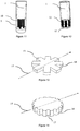
- Figure 11 shows one method for constructing the light controller.
- the light controller includes a column 9 containing optically transmissive elements (e.g. acrylic, Perspex, air etc.), the column also contains a number of non-transparent elements 10 that block light. As the light controller is rotated, alignment of the non-transparent elements changes so that the amount of light that can pass through changes.
- optically transmissive elements e.g. acrylic, Perspex, air etc.
- Figure 12 shows an alternative method for constructing the light controller.
- the light controller includes a column 11 containing optically transmissive elements.
- a number of non-transparent elements 12 e.g. paint, label, plastic etc.
- Light from a light emitter is transmitted across the light controller.
- alignment of the non-transparent elements changes so that the amount of light that can pass across changes.
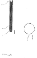
- Figure 13 shows yet another method for constructing the light controller.
- the light controller features a circular member 16 constructed of an optically transmissive material.
- the control member also features one or more recesses 17 that are coated or filled with a non-transparent material (e.g. paint, label, plastic etc.).
- a non-transparent material e.g. paint, label, plastic etc.
- the light controllers can be disposed to the viewing element and/or constructed to form part of a control knob or other control member (e.g. rotary control, button, linear slider control etc.).
- Light controllers placed through, on or within the viewing element are considered within the scope of the invention.
- Light controllers attached to the viewing element via a supporting member are also considered within the scope of the invention.
- the following paragraphs provide some example configurations, however other configurations are also considered within the scope of this invention.
- Figure 15 shows another embodiment of the invention in which the light controller is mounted to the viewing element using a support 19.
- the support is fixed to the viewing element and allows the depth of the viewing element (or plate) to be reduced while still retaining rigidity.
- the light controller is a circular member 18, which controls the amount of light passing across the light controller.
- a control knob can be mounted to the light controller.
- control panel comprises a converter operable to sequentially activate the light emitters, sequentially scan the light emitters and convert the output signal from the light detectors into a control signal representative of movement of the light controllers.
- the light detectors are scanned in a sequence that relates to the activation of the light emitters.
- the control panel may be utilised in a variety of environments and thus may encounter various ambient light conditions. Interference from unintended light sources such as ambient light could affect normal operation.
- the software application is able to update the graphics on the display without physical re-configuration of the control member. Therefore the position of the light controller can be changed by the software so that physically moving the light controller is not required.
Landscapes
- Engineering & Computer Science (AREA)
- Theoretical Computer Science (AREA)
- General Engineering & Computer Science (AREA)
- Physics & Mathematics (AREA)
- General Physics & Mathematics (AREA)
- Human Computer Interaction (AREA)
- Automation & Control Theory (AREA)
- Computer Hardware Design (AREA)
- Computer Graphics (AREA)
- Position Input By Displaying (AREA)
- Control Of Indicators Other Than Cathode Ray Tubes (AREA)
- Mechanical Light Control Or Optical Switches (AREA)
- Switches With Compound Operations (AREA)
- Input From Keyboards Or The Like (AREA)
- Electroluminescent Light Sources (AREA)
- Mechanical Control Devices (AREA)
- Switches Operated By Changes In Physical Conditions (AREA)
Claims (16)
- Steuerpaneel, das Folgendes umfasst;
ein Anzeigeelement (2), das im Gebrauch über einem Display (5), das zum Anzeigen von Bildern auslegbar ist, positioniert ist, wobei mindestens ein Teil des Displays (5) durch das Anzeigeelement (2) sichtbar ist;
mindestens zwei Lichtregler (1), die zum Anzeigeelement (2) bewegbar angeordnet sind, wobei jeder Lichtregler (1) relativ zum Anzeigeelement (2) um eine Drehachse (26) drehbar ist;
mindestens zwei Lichtemitter (3) wobei jeder Lichtemitter (3) betreibbar ist, Licht über das Anzeigeelement (2) zu mindestens einem der mindestens zwei Lichtregler (1) zu leiten; und mindestens zwei Lichtdetektoren (4), wobei jeder Lichtdetektor (4) betreibbar ist, Licht von mindestens einem der mindestens zwei Lichtregler (1) zu detektieren;
dadurch gekennzeichnet, dass;
die mindestens zwei Lichtemitter (3) und die mindestens zwei Lichtdetektoren (4) dazu angeordnet sind, ein Raster von Erfassungspfaden (6) mit zwei oder mehr einander schneidenden Erfassungspfaden (6) über das Anzeigeelement (2) zu bilden;
die mindestens zwei Lichtregler (1) durch sequenzielles Aktivieren der mindestens zwei Lichtemitter (3) und der mindestens zwei Lichtdetektoren (4) abgetastet werden;
wobei das Licht, das über das Anzeigeelement (2) zu einem Lichtregler (1) geleitet wird, in eine Richtung im Wesentlichen parallel zur Ebene des Anzeigeelements (2) über die Lichtregler (1) übertragen wird; und
das Licht, das von den mindestens zwei Lichtdetektoren (4) detektiert wird, für eine Drehbewegung der mindestens zwei Lichtregler (1) repräsentativ ist und verwendet wird, um das vom Display (5) angezeigte Bild auszulegen. - Steuerpaneel nach Anspruch 1, wobei die mindestens zwei Lichtregler (1) positioniert sind, wo sich zwei oder mehr Erfassungspfade (6) schneiden.
- Steuerpaneel nach Anspruch 2, das ein Array von Lichtreglern (1) aufweist.
- Steuerpaneel nach Anspruch 1, wobei das Licht, das über das Anzeigeelement (2) zu den mindestens zwei Lichtreglern (1) geleitet wird, in eine Richtung über die jeweiligen mindestens zwei Lichtregler (1) übertragen wird, wobei die Richtung im Wesentlichen parallel zur Ebene des Anzeigeelements (2) verläuft.
- Steuerpaneel nach Anspruch 4, wobei das Licht, das über das Anzeigeelement (2) zu einem Lichtregler (1) geleitet wird, in einer geraden Linie durch den Lichtregler (1) übertragen wird und ein Abschnitt des Lichts, der vom zugehörigen Lichtdetektor (4) detektiert wird, über den Lichtregler (1) übertragen wird, ohne reflektiert zu werden.
- Steuerpaneel nach Anspruch 1, wobei das Anzeigeelement (2) eine Platte umfasst, von der mindestens Teile transparent sind.
- Steuerpaneel nach Anspruch 1, wobei die mindestens zwei Lichtregler (1) sich mindestens teilweise durch das Anzeigeelement (2) erstrecken.
- Steuerpaneel nach Anspruch 1, wobei mindestens einer der mindestens zwei Lichtregler (1) relativ zum Anzeigeelement (2) herunterdrückbar ist, was von mindestens einem der mindestens zwei Lichtdetektoren (4) detektiert wird, wodurch mindestens einer der mindestens zwei Lichtregler (1) ferner die Funktion eines Schalters aufweist.
- Steuerpaneel nach Anspruch 1, wobei die mindestens zwei Lichtemitter (3) dazu ausgelegt sind, Licht durch das Anzeigeelement (2) zu leiten, und die mindestens zwei Lichtdetektoren (4) dazu ausgelegt sind, Licht durch das Anzeigeelement (2) zu empfangen, wobei das Anzeigeelement (2) als Lichtleiter fungiert.
- Steuerpaneel nach Anspruch 9, wobei das Anzeigeelement (2) mindestens einen Lichtdeflektor (25) beinhaltet, der gegebenenfalls reflektierend ist, um Licht zwischen den Lichtemittern (3), den Lichtreglern (1) und den Lichtdetektoren (4) indirekt zu richten.
- Steuerpaneel nach einem der Ansprüche 1 bis 10, wobei jeder der mindestens zwei Lichtregler (1) ein Merkmal beinhaltet, wobei das Merkmal dem übertragenen Licht eine Eigenschaft bereitstellt, die für eine Bewegung des jeweiligen Lichtreglers (1) repräsentativ ist.
- Steuerpaneel nach Anspruch 11, wobei das Merkmal ein oder mehrere der folgenden Elemente umfasst, die um die Drehachse des jeweiligen Lichtreglers (1) angeordnet sind;
lichtübertragende Elemente und nicht lichtübertragende Elemente (10, 12); lichtdämpfende Elemente. - Steuerpaneel nach Anspruch 11, das ferner einen Wandler umfasst, der zu Folgendem ausgelegt ist; sequenzielles Aktivieren der mindestens zwei Lichtemitter (3); sequenzielles Abtasten der mindestens zwei Lichtdetektoren (4);
Umwandeln von mindestens zwei Ausgangssignalen von den mindestens zwei Lichtdetektoren (4) in ein Steuersignal, das für eine Bewegung der mindestens zwei Lichtregler (1) repräsentativ ist. - Steuerpaneel nach Anspruch 13, wobei der Wandler ein Steuersignal bereitstellt, das für eine Richtung einer Bewegung der mindestens zwei Lichtregler (1), die durch einen Vergleich der Ausgangssignale von mindestens zwei der mindestens zwei Lichtdetektoren (4) bestimmt wird, repräsentativ ist.
- Steuerpaneel nach Anspruch 14, wobei bei einer Drehung eines Lichtreglers (1) zwei Lichtdetektoren (4) sich wiederholende Signale mit einer Phasendifferenz ausgeben und das Raster von Erfassungspfaden (6) derart ausgelegt ist, dass zwischen den zwei Signalen ungefähr eine Phasendifferenz von 90 Grad oder 270 Grad besteht.
- System, das Folgendes umfasst: das Steuerpaneel nach Anspruch 11 und eine Vorrichtung, die durch einen Betrieb des Steuerpaneels gesteuert wird.
Priority Applications (2)
| Application Number | Priority Date | Filing Date | Title |
|---|---|---|---|
| EP18195474.4A EP3454188A1 (de) | 2012-01-22 | 2013-01-09 | Bedienfeld |
| PL13704995T PL2805221T3 (pl) | 2012-01-22 | 2013-01-09 | Tablica połączeń |
Applications Claiming Priority (4)
| Application Number | Priority Date | Filing Date | Title |
|---|---|---|---|
| GB1201025.2A GB2498716A (en) | 2012-01-22 | 2012-01-22 | A Control Panel for an Electronic Display |
| GBGB1207435.7A GB201207435D0 (en) | 2012-01-22 | 2012-04-30 | A control panel |
| GB1214660.1A GB2498601A (en) | 2012-01-22 | 2012-08-16 | A Control Panel |
| PCT/GB2013/000008 WO2013108002A1 (en) | 2012-01-22 | 2013-01-09 | Control panel |
Related Child Applications (1)
| Application Number | Title | Priority Date | Filing Date |
|---|---|---|---|
| EP18195474.4A Division EP3454188A1 (de) | 2012-01-22 | 2013-01-09 | Bedienfeld |
Publications (2)
| Publication Number | Publication Date |
|---|---|
| EP2805221A1 EP2805221A1 (de) | 2014-11-26 |
| EP2805221B1 true EP2805221B1 (de) | 2018-10-10 |
Family
ID=45840783
Family Applications (2)
| Application Number | Title | Priority Date | Filing Date |
|---|---|---|---|
| EP13704995.3A Active EP2805221B1 (de) | 2012-01-22 | 2013-01-09 | Bedienfeld |
| EP18195474.4A Withdrawn EP3454188A1 (de) | 2012-01-22 | 2013-01-09 | Bedienfeld |
Family Applications After (1)
| Application Number | Title | Priority Date | Filing Date |
|---|---|---|---|
| EP18195474.4A Withdrawn EP3454188A1 (de) | 2012-01-22 | 2013-01-09 | Bedienfeld |
Country Status (10)
| Country | Link |
|---|---|
| US (2) | US9626004B2 (de) |
| EP (2) | EP2805221B1 (de) |
| JP (1) | JP6051235B2 (de) |
| CN (3) | CN107102780B (de) |
| CA (1) | CA2862234C (de) |
| ES (1) | ES2722804T3 (de) |
| GB (3) | GB2498716A (de) |
| PL (1) | PL2805221T3 (de) |
| PT (1) | PT2805221T (de) |
| WO (1) | WO2013108002A1 (de) |
Families Citing this family (7)
| Publication number | Priority date | Publication date | Assignee | Title |
|---|---|---|---|---|
| EP2830039B1 (de) * | 2013-07-24 | 2018-10-03 | Native Instruments GmbH | Verfahren, Anordnung, Computerprogramm und computerlesbare Speichermedien zur Steuerung mindestens eines Parameters oder mindestens eines Objekts mit Eingabeelementen für Kapazitätsmessung |
| US10804897B2 (en) * | 2014-01-10 | 2020-10-13 | Touchplus Information Corp. | Touch-sensitive keypad control device |
| WO2017140753A1 (en) | 2016-02-17 | 2017-08-24 | Martin Eurlings | Control panels and methods of controlling |
| GB2558667A (en) * | 2017-01-17 | 2018-07-18 | T Phy Ltd | Optical input devices |
| US11302288B2 (en) * | 2018-09-28 | 2022-04-12 | Apple Inc. | Ambient saturation adaptation |
| US20210157442A1 (en) * | 2019-11-25 | 2021-05-27 | Beechrock Limited | Interaction touch objects |
| TWI853527B (zh) * | 2023-04-14 | 2024-08-21 | 達運精密工業股份有限公司 | 非接觸按鈕 |
Citations (2)
| Publication number | Priority date | Publication date | Assignee | Title |
|---|---|---|---|---|
| GB2214637A (en) * | 1988-01-29 | 1989-09-06 | Sony Corp | Touch panel apparatus |
| WO2011153947A1 (zh) * | 2010-06-09 | 2011-12-15 | 北京汇冠新技术股份有限公司 | 一种红外发射管及触摸屏 |
Family Cites Families (21)
| Publication number | Priority date | Publication date | Assignee | Title |
|---|---|---|---|---|
| JPS54150147A (en) * | 1978-05-17 | 1979-11-26 | Canon Inc | Light attenuator |
| WO1993001564A1 (en) * | 1991-07-11 | 1993-01-21 | Dan Inbar | Position sensing display device |
| JP2504894B2 (ja) * | 1992-06-27 | 1996-06-05 | フジミ光機株式会社 | キ−ボ−ドの打鍵キ−判別方法及びその打鍵キ−判別装置 |
| EP1389773A1 (de) * | 1993-11-05 | 2004-02-18 | Intertactile Technologies Corporation | Bedienerschnittstelle mit eingebautem Anzeigeschirm |
| US5777603A (en) * | 1993-11-05 | 1998-07-07 | Intertactile Technologies Corporation | Flat panel display with optical signal transparent zone |
| US5805145A (en) * | 1993-11-05 | 1998-09-08 | Intertactile Technologies Corporation | Circuit control panel displaying changeable graphics |
| US5936613A (en) * | 1993-11-05 | 1999-08-10 | Intertactile Technologies Corporation | Rotary circuit control devices with changeable graphics |
| US6642919B1 (en) * | 2000-04-18 | 2003-11-04 | Intertactile Technologies Corporation | Integrated electrical controls and graphics display screens |
| CN2534652Y (zh) * | 2002-04-09 | 2003-02-05 | 上海贝思特电梯部件有限公司 | 条形显示装置 |
| US7133032B2 (en) * | 2003-04-24 | 2006-11-07 | Eastman Kodak Company | OLED display and touch screen |
| US20050016824A1 (en) | 2003-07-23 | 2005-01-27 | Andrew Olcott | System and method for accepting a user control input |
| US20050115816A1 (en) * | 2003-07-23 | 2005-06-02 | Neil Gelfond | Accepting user control |
| US20050018172A1 (en) * | 2003-07-23 | 2005-01-27 | Neil Gelfond | Accepting user control |
| CN1702605A (zh) | 2004-04-05 | 2005-11-30 | 伯斯有限公司 | 接收用户控制器 |
| US8189011B2 (en) * | 2005-12-22 | 2012-05-29 | Koninklijke Philips Electronics N.V. | System and method for controlling lighting systems |
| US8102365B2 (en) * | 2007-05-14 | 2012-01-24 | Apple Inc. | Remote control systems that can distinguish stray light sources |
| FR2921168B1 (fr) * | 2007-09-17 | 2011-11-18 | Peugeot Citroen Automobiles Sa | Interface de commande hybride mecanique et virtuelle |
| JP4580432B2 (ja) * | 2008-03-24 | 2010-11-10 | 京セラ株式会社 | キー押下検出装置並びにこれを備えた電子機器及び通信機器 |
| US8660300B2 (en) * | 2008-12-12 | 2014-02-25 | Silicon Laboratories Inc. | Apparatus and method for optical gesture recognition |
| US8026827B1 (en) * | 2009-05-04 | 2011-09-27 | Yazaki North America, Inc. | Virtual push button switch |
| EP2515216B1 (de) * | 2009-12-16 | 2019-06-05 | Beijing Irtouch Systems Co., Ltd. | Infrarot-berührunsbildschirm |
-
2012
- 2012-01-22 GB GB1201025.2A patent/GB2498716A/en not_active Withdrawn
- 2012-04-30 GB GBGB1207435.7A patent/GB201207435D0/en not_active Ceased
- 2012-08-16 GB GB1214660.1A patent/GB2498601A/en not_active Withdrawn
-
2013
- 2013-01-09 EP EP13704995.3A patent/EP2805221B1/de active Active
- 2013-01-09 CN CN201710022454.2A patent/CN107102780B/zh active Active
- 2013-01-09 CN CN201710022414.8A patent/CN107122063A/zh active Pending
- 2013-01-09 CN CN201380006149.4A patent/CN104321724B/zh active Active
- 2013-01-09 EP EP18195474.4A patent/EP3454188A1/de not_active Withdrawn
- 2013-01-09 PT PT13704995T patent/PT2805221T/pt unknown
- 2013-01-09 JP JP2014552686A patent/JP6051235B2/ja active Active
- 2013-01-09 ES ES13704995T patent/ES2722804T3/es active Active
- 2013-01-09 WO PCT/GB2013/000008 patent/WO2013108002A1/en not_active Ceased
- 2013-01-09 CA CA2862234A patent/CA2862234C/en active Active
- 2013-01-09 US US14/373,266 patent/US9626004B2/en active Active
- 2013-01-09 PL PL13704995T patent/PL2805221T3/pl unknown
-
2017
- 2017-02-20 US US15/437,012 patent/US10359859B2/en active Active
Patent Citations (3)
| Publication number | Priority date | Publication date | Assignee | Title |
|---|---|---|---|---|
| GB2214637A (en) * | 1988-01-29 | 1989-09-06 | Sony Corp | Touch panel apparatus |
| WO2011153947A1 (zh) * | 2010-06-09 | 2011-12-15 | 北京汇冠新技术股份有限公司 | 一种红外发射管及触摸屏 |
| US20130075765A1 (en) * | 2010-06-09 | 2013-03-28 | Xinlin Ye | Infrared light-emitting diode and touch screen |
Also Published As
| Publication number | Publication date |
|---|---|
| US20170160822A1 (en) | 2017-06-08 |
| GB201201025D0 (en) | 2012-03-07 |
| JP6051235B2 (ja) | 2016-12-27 |
| GB201214660D0 (en) | 2012-10-03 |
| ES2722804T3 (es) | 2019-08-16 |
| PT2805221T (pt) | 2019-01-21 |
| CN107102780A (zh) | 2017-08-29 |
| CN104321724B (zh) | 2017-03-01 |
| CN104321724A (zh) | 2015-01-28 |
| EP2805221A1 (de) | 2014-11-26 |
| GB2498716A (en) | 2013-07-31 |
| GB2498601A (en) | 2013-07-24 |
| EP3454188A1 (de) | 2019-03-13 |
| US10359859B2 (en) | 2019-07-23 |
| JP2015505624A (ja) | 2015-02-23 |
| GB201207435D0 (en) | 2012-06-13 |
| CA2862234A1 (en) | 2013-07-25 |
| CN107122063A (zh) | 2017-09-01 |
| HK1204499A1 (en) | 2015-11-20 |
| US20150002487A1 (en) | 2015-01-01 |
| WO2013108002A1 (en) | 2013-07-25 |
| CN107102780B (zh) | 2019-11-01 |
| US9626004B2 (en) | 2017-04-18 |
| PL2805221T3 (pl) | 2019-04-30 |
| CA2862234C (en) | 2021-03-30 |
Similar Documents
| Publication | Publication Date | Title |
|---|---|---|
| US10359859B2 (en) | Control panel | |
| JP5744390B2 (ja) | 入力デバイスおよび入力デバイスを用いてユーザ入力を検出する方法 | |
| AU2010236331B2 (en) | Optical touch screen systems using reflected light | |
| US9213443B2 (en) | Optical touch screen systems using reflected light | |
| US20100238139A1 (en) | Optical touch screen systems using wide light beams | |
| KR101809678B1 (ko) | 터치스크린 장치 및 그 제어방법 그리고 디스플레이 장치 | |
| KR101675228B1 (ko) | 3차원 터치스크린 장치, 터치스크린 장치 및 그 제어방법 그리고 디스플레이 장치 | |
| HK40005840A (en) | Control panel | |
| HK1204499B (en) | Control panel | |
| KR101646562B1 (ko) | 터치스크린 장치 및 그 제어방법 그리고 디스플레이 장치 | |
| AU2013267005A1 (en) | Optical touch screen systems using reflected light | |
| JP2011086030A (ja) | 位置検出機能付き表示装置 | |
| JP2002268808A (ja) | 座標入力装置 | |
| JP2012173139A (ja) | 光学式位置検出装置 |
Legal Events
| Date | Code | Title | Description |
|---|---|---|---|
| PUAI | Public reference made under article 153(3) epc to a published international application that has entered the european phase |
Free format text: ORIGINAL CODE: 0009012 |
|
| 17P | Request for examination filed |
Effective date: 20140714 |
|
| AK | Designated contracting states |
Kind code of ref document: A1 Designated state(s): AL AT BE BG CH CY CZ DE DK EE ES FI FR GB GR HR HU IE IS IT LI LT LU LV MC MK MT NL NO PL PT RO RS SE SI SK SM TR |
|
| DAX | Request for extension of the european patent (deleted) | ||
| REG | Reference to a national code |
Ref country code: HK Ref legal event code: DE Ref document number: 1204499 Country of ref document: HK |
|
| STAA | Information on the status of an ep patent application or granted ep patent |
Free format text: STATUS: EXAMINATION IS IN PROGRESS |
|
| 17Q | First examination report despatched |
Effective date: 20170221 |
|
| REG | Reference to a national code |
Ref country code: DE Ref legal event code: R079 Ref document number: 602013044801 Country of ref document: DE Free format text: PREVIOUS MAIN CLASS: G06F0003042000 Ipc: G06F0003030000 |
|
| RIC1 | Information provided on ipc code assigned before grant |
Ipc: G06F 3/03 20060101AFI20180314BHEP Ipc: G06F 3/0362 20130101ALI20180314BHEP Ipc: H03K 17/94 20060101ALI20180314BHEP Ipc: G06F 3/042 20060101ALI20180314BHEP |
|
| GRAP | Despatch of communication of intention to grant a patent |
Free format text: ORIGINAL CODE: EPIDOSNIGR1 |
|
| STAA | Information on the status of an ep patent application or granted ep patent |
Free format text: STATUS: GRANT OF PATENT IS INTENDED |
|
| INTG | Intention to grant announced |
Effective date: 20180420 |
|
| GRAS | Grant fee paid |
Free format text: ORIGINAL CODE: EPIDOSNIGR3 |
|
| GRAA | (expected) grant |
Free format text: ORIGINAL CODE: 0009210 |
|
| STAA | Information on the status of an ep patent application or granted ep patent |
Free format text: STATUS: THE PATENT HAS BEEN GRANTED |
|
| AK | Designated contracting states |
Kind code of ref document: B1 Designated state(s): AL AT BE BG CH CY CZ DE DK EE ES FI FR GB GR HR HU IE IS IT LI LT LU LV MC MK MT NL NO PL PT RO RS SE SI SK SM TR |
|
| REG | Reference to a national code |
Ref country code: GB Ref legal event code: FG4D |
|
| REG | Reference to a national code |
Ref country code: CH Ref legal event code: EP Ref country code: AT Ref legal event code: REF Ref document number: 1052007 Country of ref document: AT Kind code of ref document: T Effective date: 20181015 |
|
| REG | Reference to a national code |
Ref country code: IE Ref legal event code: FG4D |
|
| REG | Reference to a national code |
Ref country code: DE Ref legal event code: R096 Ref document number: 602013044801 Country of ref document: DE |
|
| REG | Reference to a national code |
Ref country code: CH Ref legal event code: NV Representative=s name: FREI PATENTANWALTSBUERO AG, CH |
|
| REG | Reference to a national code |
Ref country code: SE Ref legal event code: TRGR |
|
| REG | Reference to a national code |
Ref country code: CH Ref legal event code: PK Free format text: BERICHTIGUNG PRIORITAET |
|
| REG | Reference to a national code |
Ref country code: NL Ref legal event code: FP |
|
| REG | Reference to a national code |
Ref country code: PT Ref legal event code: SC4A Ref document number: 2805221 Country of ref document: PT Date of ref document: 20190121 Kind code of ref document: T Free format text: AVAILABILITY OF NATIONAL TRANSLATION Effective date: 20190108 |
|
| REG | Reference to a national code |
Ref country code: NO Ref legal event code: T2 Effective date: 20181010 |
|
| REG | Reference to a national code |
Ref country code: LT Ref legal event code: MG4D |
|
| PG25 | Lapsed in a contracting state [announced via postgrant information from national office to epo] |
Ref country code: LV Free format text: LAPSE BECAUSE OF FAILURE TO SUBMIT A TRANSLATION OF THE DESCRIPTION OR TO PAY THE FEE WITHIN THE PRESCRIBED TIME-LIMIT Effective date: 20181010 Ref country code: IS Free format text: LAPSE BECAUSE OF FAILURE TO SUBMIT A TRANSLATION OF THE DESCRIPTION OR TO PAY THE FEE WITHIN THE PRESCRIBED TIME-LIMIT Effective date: 20190210 Ref country code: LT Free format text: LAPSE BECAUSE OF FAILURE TO SUBMIT A TRANSLATION OF THE DESCRIPTION OR TO PAY THE FEE WITHIN THE PRESCRIBED TIME-LIMIT Effective date: 20181010 Ref country code: BG Free format text: LAPSE BECAUSE OF FAILURE TO SUBMIT A TRANSLATION OF THE DESCRIPTION OR TO PAY THE FEE WITHIN THE PRESCRIBED TIME-LIMIT Effective date: 20190110 Ref country code: HR Free format text: LAPSE BECAUSE OF FAILURE TO SUBMIT A TRANSLATION OF THE DESCRIPTION OR TO PAY THE FEE WITHIN THE PRESCRIBED TIME-LIMIT Effective date: 20181010 |
|
| PG25 | Lapsed in a contracting state [announced via postgrant information from national office to epo] |
Ref country code: GR Free format text: LAPSE BECAUSE OF FAILURE TO SUBMIT A TRANSLATION OF THE DESCRIPTION OR TO PAY THE FEE WITHIN THE PRESCRIBED TIME-LIMIT Effective date: 20190111 Ref country code: RS Free format text: LAPSE BECAUSE OF FAILURE TO SUBMIT A TRANSLATION OF THE DESCRIPTION OR TO PAY THE FEE WITHIN THE PRESCRIBED TIME-LIMIT Effective date: 20181010 Ref country code: AL Free format text: LAPSE BECAUSE OF FAILURE TO SUBMIT A TRANSLATION OF THE DESCRIPTION OR TO PAY THE FEE WITHIN THE PRESCRIBED TIME-LIMIT Effective date: 20181010 |
|
| REG | Reference to a national code |
Ref country code: DE Ref legal event code: R097 Ref document number: 602013044801 Country of ref document: DE |
|
| PG25 | Lapsed in a contracting state [announced via postgrant information from national office to epo] |
Ref country code: DK Free format text: LAPSE BECAUSE OF FAILURE TO SUBMIT A TRANSLATION OF THE DESCRIPTION OR TO PAY THE FEE WITHIN THE PRESCRIBED TIME-LIMIT Effective date: 20181010 |
|
| PLBE | No opposition filed within time limit |
Free format text: ORIGINAL CODE: 0009261 |
|
| REG | Reference to a national code |
Ref country code: ES Ref legal event code: FG2A Ref document number: 2722804 Country of ref document: ES Kind code of ref document: T3 Effective date: 20190816 |
|
| STAA | Information on the status of an ep patent application or granted ep patent |
Free format text: STATUS: NO OPPOSITION FILED WITHIN TIME LIMIT |
|
| PG25 | Lapsed in a contracting state [announced via postgrant information from national office to epo] |
Ref country code: RO Free format text: LAPSE BECAUSE OF FAILURE TO SUBMIT A TRANSLATION OF THE DESCRIPTION OR TO PAY THE FEE WITHIN THE PRESCRIBED TIME-LIMIT Effective date: 20181010 Ref country code: EE Free format text: LAPSE BECAUSE OF FAILURE TO SUBMIT A TRANSLATION OF THE DESCRIPTION OR TO PAY THE FEE WITHIN THE PRESCRIBED TIME-LIMIT Effective date: 20181010 Ref country code: SM Free format text: LAPSE BECAUSE OF FAILURE TO SUBMIT A TRANSLATION OF THE DESCRIPTION OR TO PAY THE FEE WITHIN THE PRESCRIBED TIME-LIMIT Effective date: 20181010 Ref country code: MC Free format text: LAPSE BECAUSE OF FAILURE TO SUBMIT A TRANSLATION OF THE DESCRIPTION OR TO PAY THE FEE WITHIN THE PRESCRIBED TIME-LIMIT Effective date: 20181010 Ref country code: SK Free format text: LAPSE BECAUSE OF FAILURE TO SUBMIT A TRANSLATION OF THE DESCRIPTION OR TO PAY THE FEE WITHIN THE PRESCRIBED TIME-LIMIT Effective date: 20181010 |
|
| 26N | No opposition filed |
Effective date: 20190711 |
|
| PG25 | Lapsed in a contracting state [announced via postgrant information from national office to epo] |
Ref country code: LU Free format text: LAPSE BECAUSE OF NON-PAYMENT OF DUE FEES Effective date: 20190109 |
|
| REG | Reference to a national code |
Ref country code: IE Ref legal event code: MM4A |
|
| PG25 | Lapsed in a contracting state [announced via postgrant information from national office to epo] |
Ref country code: SI Free format text: LAPSE BECAUSE OF FAILURE TO SUBMIT A TRANSLATION OF THE DESCRIPTION OR TO PAY THE FEE WITHIN THE PRESCRIBED TIME-LIMIT Effective date: 20181010 |
|
| PG25 | Lapsed in a contracting state [announced via postgrant information from national office to epo] |
Ref country code: IE Free format text: LAPSE BECAUSE OF NON-PAYMENT OF DUE FEES Effective date: 20190109 |
|
| PG25 | Lapsed in a contracting state [announced via postgrant information from national office to epo] |
Ref country code: MT Free format text: LAPSE BECAUSE OF NON-PAYMENT OF DUE FEES Effective date: 20190109 |
|
| PG25 | Lapsed in a contracting state [announced via postgrant information from national office to epo] |
Ref country code: CY Free format text: LAPSE BECAUSE OF FAILURE TO SUBMIT A TRANSLATION OF THE DESCRIPTION OR TO PAY THE FEE WITHIN THE PRESCRIBED TIME-LIMIT Effective date: 20181010 |
|
| PG25 | Lapsed in a contracting state [announced via postgrant information from national office to epo] |
Ref country code: HU Free format text: LAPSE BECAUSE OF FAILURE TO SUBMIT A TRANSLATION OF THE DESCRIPTION OR TO PAY THE FEE WITHIN THE PRESCRIBED TIME-LIMIT; INVALID AB INITIO Effective date: 20130109 |
|
| REG | Reference to a national code |
Ref country code: AT Ref legal event code: UEP Ref document number: 1052007 Country of ref document: AT Kind code of ref document: T Effective date: 20181010 |
|
| PG25 | Lapsed in a contracting state [announced via postgrant information from national office to epo] |
Ref country code: MK Free format text: LAPSE BECAUSE OF FAILURE TO SUBMIT A TRANSLATION OF THE DESCRIPTION OR TO PAY THE FEE WITHIN THE PRESCRIBED TIME-LIMIT Effective date: 20181010 |
|
| REG | Reference to a national code |
Ref country code: CH Ref legal event code: U11 Free format text: ST27 STATUS EVENT CODE: U-0-0-U10-U11 (AS PROVIDED BY THE NATIONAL OFFICE) Effective date: 20260201 |
|
| PGFP | Annual fee paid to national office [announced via postgrant information from national office to epo] |
Ref country code: NL Payment date: 20260121 Year of fee payment: 14 |
|
| PGFP | Annual fee paid to national office [announced via postgrant information from national office to epo] |
Ref country code: SE Payment date: 20260121 Year of fee payment: 14 |
|
| PGFP | Annual fee paid to national office [announced via postgrant information from national office to epo] |
Ref country code: GB Payment date: 20260123 Year of fee payment: 14 |
|
| PGFP | Annual fee paid to national office [announced via postgrant information from national office to epo] |
Ref country code: ES Payment date: 20260227 Year of fee payment: 14 |
|
| PGFP | Annual fee paid to national office [announced via postgrant information from national office to epo] |
Ref country code: NO Payment date: 20260123 Year of fee payment: 14 Ref country code: DE Payment date: 20260121 Year of fee payment: 14 |
|
| PGFP | Annual fee paid to national office [announced via postgrant information from national office to epo] |
Ref country code: AT Payment date: 20260122 Year of fee payment: 14 |
|
| PGFP | Annual fee paid to national office [announced via postgrant information from national office to epo] |
Ref country code: FI Payment date: 20260129 Year of fee payment: 14 Ref country code: BE Payment date: 20260121 Year of fee payment: 14 Ref country code: IT Payment date: 20260126 Year of fee payment: 14 |
|
| PGFP | Annual fee paid to national office [announced via postgrant information from national office to epo] |
Ref country code: FR Payment date: 20260123 Year of fee payment: 14 |
|
| PGFP | Annual fee paid to national office [announced via postgrant information from national office to epo] |
Ref country code: TR Payment date: 20260108 Year of fee payment: 14 |
|
| PGFP | Annual fee paid to national office [announced via postgrant information from national office to epo] |
Ref country code: PT Payment date: 20260102 Year of fee payment: 14 Ref country code: CH Payment date: 20260201 Year of fee payment: 14 Ref country code: CZ Payment date: 20260102 Year of fee payment: 14 |
|
| PGFP | Annual fee paid to national office [announced via postgrant information from national office to epo] |
Ref country code: PL Payment date: 20260102 Year of fee payment: 14 |