EP2805133B2 - Geführter optische router, faseroptisches interferometer mit einem solchen optischer router und verfahren für geführtes optisches routing - Google Patents
Geführter optische router, faseroptisches interferometer mit einem solchen optischer router und verfahren für geführtes optisches routing Download PDFInfo
- Publication number
- EP2805133B2 EP2805133B2 EP13705211.4A EP13705211A EP2805133B2 EP 2805133 B2 EP2805133 B2 EP 2805133B2 EP 13705211 A EP13705211 A EP 13705211A EP 2805133 B2 EP2805133 B2 EP 2805133B2
- Authority
- EP
- European Patent Office
- Prior art keywords
- optical
- waveguides
- power
- waveguide
- evanescent
- Prior art date
- Legal status (The legal status is an assumption and is not a legal conclusion. Google has not performed a legal analysis and makes no representation as to the accuracy of the status listed.)
- Active
Links
- 230000003287 optical effect Effects 0.000 title claims description 172
- 238000000034 method Methods 0.000 title claims description 7
- 230000008878 coupling Effects 0.000 claims description 102
- 238000010168 coupling process Methods 0.000 claims description 102
- 238000005859 coupling reaction Methods 0.000 claims description 102
- 230000001902 propagating effect Effects 0.000 claims description 19
- 230000003993 interaction Effects 0.000 claims description 8
- 230000002457 bidirectional effect Effects 0.000 claims description 2
- 238000001514 detection method Methods 0.000 claims description 2
- 239000013307 optical fiber Substances 0.000 description 29
- 230000008901 benefit Effects 0.000 description 10
- 239000000758 substrate Substances 0.000 description 9
- 239000000835 fiber Substances 0.000 description 8
- GQYHUHYESMUTHG-UHFFFAOYSA-N lithium niobate Chemical compound [Li+].[O-][Nb](=O)=O GQYHUHYESMUTHG-UHFFFAOYSA-N 0.000 description 4
- 230000010287 polarization Effects 0.000 description 3
- 230000000694 effects Effects 0.000 description 2
- 238000005259 measurement Methods 0.000 description 2
- 230000010363 phase shift Effects 0.000 description 2
- 238000012545 processing Methods 0.000 description 2
- 230000007423 decrease Effects 0.000 description 1
- 230000003247 decreasing effect Effects 0.000 description 1
- 238000003286 fusion draw glass process Methods 0.000 description 1
- 230000001939 inductive effect Effects 0.000 description 1
- 238000002955 isolation Methods 0.000 description 1
- 238000001393 microlithography Methods 0.000 description 1
- 238000012552 review Methods 0.000 description 1
- 238000000926 separation method Methods 0.000 description 1
- 239000007787 solid Substances 0.000 description 1
- 230000003595 spectral effect Effects 0.000 description 1
- 230000032258 transport Effects 0.000 description 1
Images


Classifications
-
- G—PHYSICS
- G02—OPTICS
- G02B—OPTICAL ELEMENTS, SYSTEMS OR APPARATUS
- G02B6/00—Light guides; Structural details of arrangements comprising light guides and other optical elements, e.g. couplings
- G02B6/24—Coupling light guides
- G02B6/26—Optical coupling means
- G02B6/28—Optical coupling means having data bus means, i.e. plural waveguides interconnected and providing an inherently bidirectional system by mixing and splitting signals
-
- G—PHYSICS
- G02—OPTICS
- G02B—OPTICAL ELEMENTS, SYSTEMS OR APPARATUS
- G02B6/00—Light guides; Structural details of arrangements comprising light guides and other optical elements, e.g. couplings
- G02B6/10—Light guides; Structural details of arrangements comprising light guides and other optical elements, e.g. couplings of the optical waveguide type
- G02B6/12—Light guides; Structural details of arrangements comprising light guides and other optical elements, e.g. couplings of the optical waveguide type of the integrated circuit kind
- G02B6/122—Basic optical elements, e.g. light-guiding paths
- G02B6/125—Bends, branchings or intersections
-
- G—PHYSICS
- G01—MEASURING; TESTING
- G01C—MEASURING DISTANCES, LEVELS OR BEARINGS; SURVEYING; NAVIGATION; GYROSCOPIC INSTRUMENTS; PHOTOGRAMMETRY OR VIDEOGRAMMETRY
- G01C19/00—Gyroscopes; Turn-sensitive devices using vibrating masses; Turn-sensitive devices without moving masses; Measuring angular rate using gyroscopic effects
- G01C19/58—Turn-sensitive devices without moving masses
- G01C19/64—Gyrometers using the Sagnac effect, i.e. rotation-induced shifts between counter-rotating electromagnetic beams
- G01C19/66—Ring laser gyrometers
- G01C19/661—Ring laser gyrometers details
-
- G—PHYSICS
- G02—OPTICS
- G02B—OPTICAL ELEMENTS, SYSTEMS OR APPARATUS
- G02B6/00—Light guides; Structural details of arrangements comprising light guides and other optical elements, e.g. couplings
- G02B6/24—Coupling light guides
- G02B6/26—Optical coupling means
- G02B6/28—Optical coupling means having data bus means, i.e. plural waveguides interconnected and providing an inherently bidirectional system by mixing and splitting signals
- G02B6/2804—Optical coupling means having data bus means, i.e. plural waveguides interconnected and providing an inherently bidirectional system by mixing and splitting signals forming multipart couplers without wavelength selective elements, e.g. "T" couplers, star couplers
-
- G—PHYSICS
- G01—MEASURING; TESTING
- G01C—MEASURING DISTANCES, LEVELS OR BEARINGS; SURVEYING; NAVIGATION; GYROSCOPIC INSTRUMENTS; PHOTOGRAMMETRY OR VIDEOGRAMMETRY
- G01C19/00—Gyroscopes; Turn-sensitive devices using vibrating masses; Turn-sensitive devices without moving masses; Measuring angular rate using gyroscopic effects
- G01C19/58—Turn-sensitive devices without moving masses
- G01C19/64—Gyrometers using the Sagnac effect, i.e. rotation-induced shifts between counter-rotating electromagnetic beams
- G01C19/72—Gyrometers using the Sagnac effect, i.e. rotation-induced shifts between counter-rotating electromagnetic beams with counter-rotating light beams in a passive ring, e.g. fibre laser gyrometers
- G01C19/725—Gyrometers using the Sagnac effect, i.e. rotation-induced shifts between counter-rotating electromagnetic beams with counter-rotating light beams in a passive ring, e.g. fibre laser gyrometers using nxn optical couplers, e.g. 3x3 couplers
Definitions
- the present invention relates to an optical fiber Sagnac ring interferometer comprising a 50-50 guided bidirectional optical router for splitting an incident optical beam into two guided optical beams of the same power in one direction of propagation, and for combining two guided optical beams in an optical beam guided in the opposite direction of propagation.
- the invention also relates to a fiber optic gyroscope comprising such a guided optical router.
- the invention also relates to a reciprocal and low-loss optical routing method, particularly in an application to an optical fiber gyroscope.
- An optical splitter is commonly used to divide an optical beam into two beams of the same power, for example in an amplitude division interferometer or in an optical telecommunications router.
- a 50-50 optical splitter also called a -3dB splitter, allows an optical beam to be divided into two secondary beams of the same power.
- a 50-50 optical splitter is also used to combine in amplitude two optical beams coming from the two branches of an interferometer, such as for example from the two ends of an optical fiber gyroscope.
- it is essential that the optical splitter ensures a 50-50 distribution of the incident power independent of the wavelength of the beams as well as the environment and in particular the temperature.
- optical separators such as a semi-reflecting blade in conventional optics, a Y junction in fiber optics or integrated optics, or even an evanescent field coupler with two gates (i.e. with two input gates). and two output doors or 2x2 coupler) in fiber optics or integrated optics.
- a semi-reflecting blade in conventional optics
- a Y junction in fiber optics or integrated optics
- an evanescent field coupler with two gates i.e. with two input gates
- 2x2 coupler two output doors or 2x2 coupler
- a semi-reflecting blade makes it possible to spatially divide an incident optical beam into two optical beams each having 50% of the power of the incident beam.
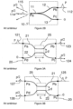
- FIG 1A schematically represents a semi-transparent blade in classic optics.
- the blade 1 receives an incident beam 2 on a gate Pa.
- the semi-reflecting blade 1 divides the incident beam 2 into a first secondary beam 3 on a gate Pb and a second secondary beam 4 on a gate Pc.
- all the power of beam 2 is distributed between beam 3 and beam 4.
- blade 1 is selected so that secondary beams 3 and 4 have the same power.
- FIG 1B represents the same semi-transparent blade 1 operating in the opposite direction. Blade 1 receives a beam 5 on gate Pb.
- Blade 1 divides beam 5 into a first secondary beam 6 on gate Pa and a second secondary beam 7 on a fourth gate Pd. By conservation of energy, all the power of beam 5 is distributed between beam 6 and beam 7. By reciprocity, the power which goes from gate Pa to gate Pb on the Figure 1A is identical to the power which goes from gate Pb to gate Pa on the Figure 1B . It is easy to understand that the semi-transparent blade functions in a similar manner regardless of the entrance door on which a light beam is incident.
- the semi-reflecting blade 1 therefore constitutes an optical router with four doors, more precisely an optical router with two input doors and two output doors.
- the 50-50 power beam splitting function can also be achieved in optics guided by an integrated optical circuit (COI) or by an optical fiber component.
- COI integrated optical circuit
- optical fiber component optical fiber component
- an integrated optical circuit with amplitude division comprising a single-mode waveguide in the form of a Y junction (cf. Figure 2A ).
- the junction 10 comprises a common branch 11 connected to a first secondary branch 12 and to a second secondary branch 13.
- An integrated optical circuit being manufactured by micro lithography techniques a Y-shaped junction 10 on an integrated optical circuit is perfectly symmetrical.
- a single-mode optical beam 14 of power p incident on the gate Pa propagates on the common branch 11 of the single-mode waveguide.
- the Y junction divides the single-mode optical beam 14 into two secondary single-mode beams 15 and 16 propagating respectively on the secondary branches 12 and 13 of the single-mode waveguide. By symmetry, each secondary beam 15, 16 receives 50% of the power of the incident beam 14.
- FIG. 2B represents the Y junction of the Figure 2A operating in the opposite direction of propagation.
- a beam 112 of power p is coupled to gate Pb while zero power is to gate Pc.
- the Y junction transmits a guided optical beam 114 on the common branch.
- the waveguide being single-mode, only one mode is guided on the common branch 11 of the Y junction.
- all the power of the beam 112 is distributed between a guided beam 114 and an unguided beam 115 .
- the power which goes from gate Pa to gate Pb on the Figure 2A is identical to the power which goes from gate Pb to gate Pa on the Figure 2B .
- the guided optical beam 114 has a power half (p/2) of the power of the incident beam 112. It is known that an antisymmetric mode 115 of power equal to p/2 propagates in an unguided manner in the substrate ( Arditty et al., “Reciprocity properties of a branching waveguide”, Fiber-Optic Rotation Sensors, Springer series in optical sciences, Vol. 32, 1982, pp. 102-110 ). There is thus a fourth unguided gate formed by this higher order antisymmetric mode. Part of this unguided mode can be collected by an optical fiber coupled to the common branch 11 of the waveguide. The signal detected on the Pa gate can thus be disturbed by the unguided mode.
- the Y junction is also a four-gate optical router, but with only three guided gates. Due to its symmetry, a Y junction is stable in wavelength and thermally.
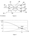
- Coupling by evanescent field consists of bringing together the cores of two single-mode waveguides 21, 22 in an interaction zone 25 of length L in a longitudinal direction parallel to the axis of the waveguides 21, 22.
- the distance d between the centers of the two waveguides in the interaction zone 25 is such that the fundamental mode propagating in the core of a single-mode waveguide is coupled by covering the evanescent wave in the guide. adjacent single-mode wave.
- a guided single-mode beam 121 of power p is coupled to the gate Pa while zero power is to the gate Pd.
- the coupler 20 divides the beam 121 into a first single-mode secondary beam 123 guided on the gate Pb and a second single-mode secondary beam 124 guided on the gate Pc.
- the interaction length of the coupling zone is generally adjusted such that half of the power of the incident beam is distributed to each of the two output waveguides, the power on gate Pb being equal to p/2 as is the power on gate Pc.
- FIG 3B represents the same evanescent field coupler 20 as on the Figure 3A now operating in the opposite direction to the direct direction of propagation.
- a guided single-mode beam 125 of power p is incident on the gate Pb.
- a 2x2 evanescent field coupler is also a four-gate optical router, with four guided gates. Compared to a Y junction, a 2x2 evanescent field coupler therefore has the advantage of guiding the beams over four gates.
- FIG. 4 represents the coupling curves of a 2x2 evanescent field coupler as shown in the Figure 3A in the direct sense.
- the dashed curve 124 represents the power coupled to the gate Pc as a function of the length L of the evanescent coupling zone 25.
- the solid curve 123 represents the remaining power on the gate Pb as a function of the length L.
- the power coupled from gate Pa to gate Pc (curve of beam 124) follows a law in sin 2 as a function of the interaction length L. By conservation of energy, the remaining power on gate Pb (curve of beam 123) follows a law in cos 2 .
- the coupling length denoted Lc
- all the power of an incident optical beam injected onto the first gate Pa of the first waveguide 21 is entirely coupled into the second waveguide 22, which corresponds to the maximum of the coupling power curve 124 (cf. Figure 3 ).
- the power on the gate Pb is zero.
- the interaction length L of the evanescent coupling zone is adjusted to Lc/2, so that half of the incident power is transmitted to gate Pb and the other half coupled to gate Pc.
- Figure 5 indicates the operating point at Lc/2 of a 2x2 and 50-50 evanescent field coupler. It is observed that this operating point corresponds to a maximum slope of the power curves 123 and 124.
- a variation in the wavelength of the beam or the surrounding conditions produces a variation in the coupling force, therefore in Lc which generates a strong variation of the power transmitted on the gate Pb and coupled on the gate Pc.
- any disturbance induces a deviation from the operating point at Lc/2, hence an imbalance between the power transmitted on the gate Pb and coupled on the gate Pc (represented schematically by an arrow on the Figure 5 ).
- a 2x2 and 50-50 coupler per evanescent field therefore does not present good stability, particularly in wavelength.
- an optical coupler 30 with three input doors and three output doors (or 3x3 coupler) on optical fibers in which the cores of three optical fibers are brought together by fusion- stretching, so that the cores of the three fibers extend parallel in the same sheath over a coupling zone 35 (cf. Figure 6 ).
- a 3x3 optical coupler per evanescent field 30 is generally adjusted (during fusion-stretching the distance between fibers decreases simultaneously with the increase in the interaction length) so that a beam 36 of power p entering on a input gate Pa is equally distributed into three beams 37, 38, 39 having identical power (respectively p/3, p/3, p/3) on each of the three output gates Pb, Pc, Pd.
- FIG. 7 represents the coupling curves of a 1/3, 1/3, 1/3 router. For a length L of the evanescent coupling zone equal to L eq the power on the gate Pb is equal to the power on the gates Pc and Pd, and equal to one third of the incident power on the gate Pa.
- the operating point at 1/3 on the coupling curves corresponds to a high slope. This operating point is therefore sensitive to variations in wavelength and/or temperature. A router equally distributed 1/3, 1/3, 1/3 is therefore not very stable, particularly in terms of wavelength.
- a planar integrated optical circuit comprising a 3x3 evanescent field coupler comprising three parallel waveguides on a coupling zone 35 by evanescent field.
- An input signal 36 of power p on the gate Pa of the central waveguide 31 is distributed in energy in a balanced manner on the three output gates Pb, Pc, Pd with the same power (respectively p/3, p/ 3, p/3).
- These 3x3 to 1/3-1/3-1/3 couplers have interesting phase shift properties which make them useful in fiber optic gyroscope applications (cf. SK Sheem “Fiber-Optic Gyroscope With [3x3] Directional Coupler” Applied Physics Letters, Vol. 37, 1980, pp. 869-871 ).
- the document US 4,653,917 also describes a 3x3 evanescent field coupler configured to split an incident beam into three beams of equal power.
- the document P. Ganguly, JC Biswas, S. Das, SK Lahiri “A three waveguide polarization independent power splitter on lithium niobate substrate”, Optics Comm. 168 (1999) 349-354 describes a power divider on an optical integrated circuit comprising a single-mode input waveguide and two single-mode output waveguides arranged on either side of the input waveguide in a coupling zone by evanescent field.
- the length L of the coupling zone is adapted to divide an optical beam propagating on the central waveguide into two optical beams of the same power propagating on the two lateral output waveguides.
- This power divider works analogously to a Y junction.
- a Y junction has the advantage, due to its symmetry, of being stable in wavelength and temperature but has the disadvantage of presenting an unguided fourth gate.
- a 2x2 evanescent field coupler has the advantage of guiding all the gates, but has the disadvantage of being not very stable, particularly in terms of wavelength.
- An equally distributed 3x3 coupler (1/3, 1/3, 1/3) has the advantage of guiding all the gates, but has the disadvantage of being not very stable, particularly in wavelength.
- an equally distributed 3x3 coupler has the disadvantage of inducing a loss of a third of the input power.
- the document US 4,653,917 describes an optical gyroscope comprising a 3x3 input coupler.
- the present invention aims to remedy the drawbacks of prior techniques and relates more particularly to an interferometer according to claim 1.
- the evanescent field optical coupling zone of the 3x3 evanescent field optical coupler has a coupling length L between 1.3154 x L eq and 2 x L eq where L eq represents the equally distributed coupling length in power for an evanescent field optical reference coupler with three input gates and three output gates, having the same distances between waveguides and under the same conditions of wavelength of the beams and temperature, so as to that for said coupling length L (between 1.3154 x L eq and 2 x L eq ) an optical beam coupled to the first input gate having a power p and propagating on the first central waveguide in the forward direction is divided into a first secondary beam having a power greater than or equal to 90% of p/2 on the second output gate and another secondary beam having the same power greater than or equal to 90% of p/2 on the third output gate, and said first, second and third waveguides move away from each other outside the optical coupling zone between each of the input gates and the optical coupling zone and respectively
- Each of said three input gates and three output gates is thus connected respectively to a separate optical waveguide capable of guiding an optical beam from said input gate or respectively from said output gate towards the field coupling zone evanescent and reciprocally to guide an optical beam coming from the coupling zone towards said input door or respectively said output door.
- a reference 3x3 evanescent field coupler is said to be equi-distributed in output power, when an incident beam of power p on the input gate Pa of the equi-distributed coupler is divided into three secondary beams of the same power p/3 on the three output gates Pb, Pc and Pd respectively.
- the optical coupling zone by evanescent field of the 3x3 evanescent field optical coupler has a coupling length L between 1.55 x L eq and 1.74 x L eq so that, for said length of coupling L, an optical beam coupled to the first input gate having a power p and propagating on the first central waveguide in the direct direction is divided into a first secondary beam having a power greater than or equal to 99% of p/2 on the second output gate and another secondary beam having the same power greater than or equal to 99% of p/2 on the third output gate.
- the coupling length L is equal to 1.6443 x L eq .
- said guided optical router comprises an optical circuit integrated on a planar substrate, said first, second and third waveguides extending in a plane parallel to said planar substrate, the first guide d the central wave being located equidistant from the second and third lateral waveguide in the optical coupling zone by evanescent field.
- said first, second and third waveguides are optical fiber waveguides, said optical coupling zone by evanescent field being a fusion-stretching zone of said first, second and third waveguides, said first, second and third waveguides being located mutually equidistant in the evanescent field optical coupling zone.
- the Sagnac ring interferometer further comprises a second guided optical router according to one of the embodiments described, the second guided optical router being arranged in series between the source, the detector and the first guided optical router, the central waveguide of the first guided optical router being optically connected to the central waveguide of the second guided optical router.
- At least one of the two secondary inputs of the first optical router is connected to optical detection means capable of detecting at least one return secondary optical beam.
- the invention also proposes an optical routing method according to claim 3.
- the invention will find a particularly advantageous application in an optical fiber Sagnac ring interferometer used in an optical fiber gyroscope or as an electric current or magnetic field sensor by Faraday effect.
- the present invention also concerns the characteristics which will emerge during the description which follows and which must be considered in isolation or in all their technically possible combinations.
- the invention is based on the use of a 3x3 evanescent field coupler comprising three single-mode waveguides 31, 32, 33 adjacent to a coupling zone 35 by evanescent field.
- this 3x3 evanescent field coupler 40 is configured differently from a coupler 30 of the prior art as described in connection with the Figure 6 .
- the 3x3 evanescent field coupler 40 of the invention is also configured differently from the power divider-coupler described in the document P. Ganguly, JC Biswas, S. Das, SK Lahiri “A three waveguide polarization independent power splitter on lithium niobate substrate”, Optics Comm. 168 (1999) 349-354 .
- the central single-mode waveguide terminates at one end of a coupling zone and the two side single-mode waveguides terminate at the other end of the evanescent field coupling zone.
- this component functions as a Y-junction by dividing a guided beam propagating on the central waveguide into two guided beams propagating on the side waveguides.
- this component also functions as a Y junction: two beams propagating respectively on the two lateral waveguides towards the coupling zone combine to form a symmetrical mode beam guided on the waveguide central and an antisymmetric mode beam propagating in an unguided manner in the substrate.
- the optical integrated circuit comprises a 3 x 3 coupler, comprising an evanescent field coupling zone 35 in which three single-mode waveguides 31, 32, 33 are preferably arranged in parallel.
- Two lateral waveguides 32, 33 are arranged symmetrically with respect to a central waveguide 31.
- the distance d between the central waveguide 31 and each of the lateral waveguides 32, 33 is preferably constant over the entire coupling zone 35, that is to say over a length L.
- the distance between the waveguides 31, 32, 33 and the length of the coupling zone 35 by evanescent field are determined and adjusted precisely to allow the operation of the optical coupler 40.
- the waveguide is manufactured by proton exchange on a lithium niobate substrate, the wavelength of the incident beam is equal to 1530 nm, the length interaction L is equal to 4mm, the width of a waveguide is equal to 6 ⁇ m, the refractive index of the waveguide is equal to 2.15 and the distance d between the center of the guide d
- the central wave 31 and the center of any one of the lateral waveguides 32 or 33 is equal to approximately 14 ⁇ m.
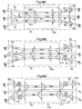
- FIG. 10A represents the operation of the optical coupler 40 in the direct direction of propagation.
- the evanescent coupling zone 35 of an optical coupler according to a preferred embodiment of the invention.
- a single-mode optical beam 36 of power p is injected onto the input gate Pa of the central waveguide 31, while no optical beam is coupled onto the input gates Pe and Pf of the two guides lateral waves 32, 33.
- the beam incident has a spatial distribution of power centered on the central waveguide 31, with a maximum on the central waveguide and extends decreasing towards the lateral waveguides 32, 33.
- the distance d between the guide central 31 and the lateral guide 32, respectively 33, is such that the incident beam has an energy overlap zone 362 on the lateral waveguide 32 and symmetrically an energy overlap zone 363 on the lateral waveguide 33.
- the incident beam 36 is progressively coupled by overlap and symmetrically in the two lateral waveguides 32, 33.
- the 3x3 coupler always remains symmetrical for the lateral channels.
- the spatial power distribution of the beam presents two maxima centered respectively on each of the lateral waveguides 32, 33 and a minimum on the central waveguide 31
- Lc' half of the power of the incident beam 36 is transferred to a lateral waveguide 32 and the other half of the power of the incident beam is transferred to the other lateral waveguide 33.
- a secondary beam 42, respectively 43, of power equal to p/2 propagates.
- the secondary optical output beams 42 and 43 are in phase.
- the central output Pb of the central waveguide 31 only a secondary beam 41 of almost zero residual power ( ⁇ 1) propagates. We thus obtain a 50-50 optical router or optical splitter perfectly balanced in power between the gate Pc and the gate Pd due to the symmetry of this optical coupler.
- the length L of the evanescent coupling zone 35 for a distance d between the waveguides in this zone 35 can be determined in practice by coupling an incident beam onto the input Pa of the central guide and by measuring the intensity on the Pb output of this central waveguide.
- the length L of the coupling zone of a 3x3 coupler is equal to a length L eq the power incident on the input gate Pa is equally distributed in three thirds on the three output gates Pb, Pc and Pd.
- the coupling curve on the gates Pc and Pd follows a law in (1 ⁇ 2 x sin 2 ( ⁇ /2 x L/ Lc')).
- the power curve transmitted on the gate Pb follows a law in cos 2 ( ⁇ /2 x L/ Lc').
- the length L of the coupling zone 35 of an equally distributed 3x3 coupler is extended, while maintaining the same distances between waveguides, and therefore the same coupling force between adjacent waveguides.
- the power on gate Pb is zero, while the power coupled on gate Pc and on gate Pd is equal to p/ 2.
- the intensity on the Pb output is zero, this corresponds to the 50-50 separation operating point between the two side outputs Pc and Pd.
- the operating point of the 3x3 optical router at 50-50 corresponds to a value L equal to Lc' such that 1 ⁇ 2 sin 2 ( ⁇ /2 x Lc'/ Lc') is equal to 1/2 and cos 2 ( ⁇ /2 x Lc'/ Lc') is equal to 0.
- Lc' is equal to L eq x 1.6443
- the operating point of the 50-50 optical router of the invention is located at a maximum of the power distribution curve for the gates Pc and Pd and at a minimum for the gate Pb. At these minimum and maximum points of the power distribution curves coupling, the 50-50 router of the invention has great stability both in wavelength and in temperature.
- the length L of the optical router 50-50 of the invention is between a length L such that more than 90% of the power p/2 is transferred to the gates Pc and Pd of the waveguides lateral, which corresponds to a length L between 0.8xLc' and 1.2xLc' or to a length L between 1.3154 x L eq and 2 x L eq .
- the length L of the optical router 50-50 of the invention is between a length L such that more than 99% of the power p/2 is transferred to the gates Pc and Pd of the guides lateral waves, which corresponds to a length L between 0.94xLc' and 1.06xLc' or to a length L between 1.55 x L eq and 1.74 x L eq .
- the length Lc' is equal to 1.6443 times the length L eq of an equi-distributed 3x3 coupler, which remains compatible with the length of a COI substrate of 40 to 50 mm.
- the first waveguide 31, the second waveguide 32, and the third waveguide 33 move away from each other between each of the input doors, respectively Pa, Pe, Pf and the optical coupling zone 35.
- the first waveguide 31, the second waveguide 32, and the third waveguide 33 move away from each other between the zone optical coupling 35 and each of the output gates respectively Pb, Pc, Pd.
- the beams guided on the different waveguides 31, 32, 33 propagate in a guided and independent manner on each waveguide 31, 32, 33 outside the optical coupling zone 35.
- FIG. 10B represents the operation of the 50-50 router in symmetrical mode, in the opposite direction of beam propagation. This operation is reciprocal compared to the operation in the direct direction of the Figure 10A .
- a beam 52 of power p/2 is coupled to the output Pc of the second lateral waveguide 32 and that a beam 53 of the same power p/2 is coupled to the output Pd of the third guide lateral wave 33, the two beams 52 and 53 being single-mode and in phase ( Fig. 10B ).
- no optical beam is coupled onto the output Pb of the central waveguide 31.
- the two beams 52, 53 enter the evanescent coupling zone 35.
- the beam 52 and the beam 53 are in phase and each have an overlapping zone with the central waveguide 31.
- the two overlapping zones overlap on the central waveguide 31 to form an energy overlapping zone 511. Due to the overlap with the central waveguide 31, these two beams 52, 53 in phase are entirely coupled in the central waveguide 31 after a coupling length L equal to Lc', that is to say at the other end of the evanescent coupling zone 35, where the waveguides 31, 32, 33 are away from each other.
- Lc' the coupling length of the two incident beams on the entrance gate Pa of the central waveguide 31 (beam 61), while on each of the two entrance gates Pe, Pf of the lateral waveguides 32 , 33 the power of the secondary return beams 62 and 63 is almost zero ( ⁇ ' ⁇ 1).
- FIG. 10C represents the operation of the 50-50 router in antisymmetric mode.
- a beam 72 of power p/2 is coupled to the output Pc of the second lateral waveguide 32 and that a beam 73 of the same power p/2 is coupled to the output Pd of the third waveguide lateral 33, the two beams 72, 73 being single-mode and in phase opposition ( Fig. 10C ).
- the two beams 72, 73 enter the evanescent coupling zone 35.
- the two beams 72, 73 partially overlap in the central waveguide 35.
- the two beams 72, 73 being in phase opposition, the energetic superposition of the overlapping zones is canceled in the central waveguide 31. There is then no coupling in the central waveguide 31.
- each lateral waveguide 32, respectively 33 transports a beam 82, respectively 83 retaining almost the same power as at the entrance to the evanescent coupling zone 35, the beams 82, 83 being in phase opposition.
- a beam 82 having a power ⁇ p/2 on the entrance gate Pe of the lateral waveguide 32 a beam 83 having a power ⁇ p/2 on the entrance gate Pf of the other guide lateral waveguide 33 and a beam 81 of almost zero power ( ⁇ 1) on the input gate Pa of the central waveguide 31.
- the antisymmetric mode of the 3x3 router is therefore distributed 50-50 between the gates d input Pe and Pf of the lateral waveguides 32 and 33.
- the advantage of the 3x3 coupler thus configured is to make it possible to optically guide the antisymmetric mode, which avoids disturbing the signal on the central gate, unlike the case of the Y junction.
- FIG. 10D represents the operating mode of the router 50-50 in the opposite direction of beam propagation when only a beam 73 of power p is coupled to the output Pd of the third lateral waveguide 33 and therefore when no power is coupled to the gates Pb and Pc of the waveguides 31 and 32 respectively.
- the mode of operation of the Figure 10D corresponds to the linear combination of the modes represented on the Figure 10B and on the Figure 10C .
- the beam 73 can be decomposed into a symmetrical mode 732 with two lobes of power p/2 and centered on the waveguides 32 and 33 and an antisymmetric mode 731 also of power p/2 on these same waveguides 32 and 33.
- the two-lobe symmetrical and antisymmetrical modes are in phase on waveguide 33 where there is light, and in opposition to phase on waveguide 32 where there is no light.
- the two-lobe symmetric mode 732 coupled completely to the central waveguide, while the antisymmetric mode 731 remained in the two side guides.
- gate Pa a beam 81 of power equal to p/2
- gate Pe a beam 82 of power equal to p/4
- gate Pf a beam 83 of power equal to p/4.
- the 50-50 optical router of the invention has the advantage of guiding all the optical beams and of having great stability, particularly in wavelength.
- the 50-50 router is manufactured on a planar optical integrated circuit.
- a 50-50 optical router can be manufactured on optical fiber by fusion-drawing from three optical fibers.
- the core of each of the three optical fibers is located at the vertices of an equilateral triangle.
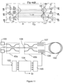
- the gyroscope comprises two 50-50 routers based on 3x3 and 50-50 couplers, as described above.
- the gyroscope includes an optical fiber coil 102, a light source 100, a detector 101, a first optical router 40a, an optical integrated circuit (IOC) including a second optical router 40b and a pair of integrated phase modulators 106, 107
- the central waveguide of the first router 40a is optically connected by a single-mode optical fiber 108 to the central waveguide of the second optical router 40b.
- the gyroscope also includes an analog-to-digital converter 103, a digital processor 104 and a digital-to-analog converter 105.
- the first optical router 40a functions as a beam splitter to separate the source 100 from the detector 101.
- a conventional beam splitter or an optical circulator can be used instead of the first 40a optical router.
- the optical router 40b has three waveguides and is configured so to obtain a 50-50 energy distribution on the two lateral waveguides.
- the length L of the evanescent coupling zone 35 is between 0.8xLc' and 1.2x Lc', where Lc' is the lateral coupling length 50-50 as defined above.
- the length L of the evanescent coupling zone 35 is between 1.3154 x L eq and 2 x L eq where L eq represents the length for an equi-distributed coupling in power (1/3, 1/3, 1 /3).
- the light source 100 emits an incident optical beam which is directed towards a first input of the optical router 40a.
- the energy distribution is controlled so that the power on the output gate Pb is less than 10% of the incident power. Even more advantageously, the power on the output gate Pb less than 1% of the incident power.
- the power on the output gate Pb of the first waveguide is minimized, this corresponds to the 50-50 operating point of the optical router 40b.
- One end of the optical fiber spool 102 is optically coupled to an output of the COI 40b, the other end of the optical fiber spool 102 is optically coupled to another output of the COI 40b.
- a secondary beam having a power equal to p/2 propagates in the direct direction of the optical fiber coil 102
- another secondary beam having a power equal to p/2 propagates in the opposite direction of the optical fiber coil 102.
- the two secondary beams are in phase. After propagation along the optical fiber coil, respectively in the direct direction and in the reverse direction, the secondary beams undergo, by Sagnac effect, a relative phase shift which is proportional to the rotation speed of the optical fiber coil 102.
- Electrodes 106, 107 deposited on either side of the waveguides of the COI 40b make it possible to modulate the phase of the optical beams to improve signal processing.
- a first beam is collected on a lateral waveguide and a second beam on another waveguide of COI 40b.
- the antisymmetric reciprocal mode propagates on the central waveguide of the router 40b then on the optical fiber 108 towards another router 40a (or a separator or a circulator) and is coupled towards the detector 101
- a converter 103 converts the analog signal from the detector into a digital signal. After processing the signal, we obtain a signal Sr representative of a measurement of rotation of the optical fiber coil 102.
- the processor calculates the modulation to be applied to the electrodes of the phase modulator 106, 107 via the converter 105.
- secondary signals propagating on the gates Pe and Pf of the second optical router 40b can be measured.
- the gyroscope of the Figure 11 has the advantage of allowing rotation measurement while guiding the antisymmetric reciprocal mode on another guided gate.
- the 50-50 guided optical router allows, by double lateral coupling, to divide an incident single-mode optical beam into two single-mode optical beams of the same power (i.e. -3dB) in the forward direction.
- the optical router of the invention makes it possible to combine two optical beams and direct them without loss to form a symmetrical mode guided towards a door and an antisymmetric mode also guided towards one or two other doors.
- the evanescent field optical router has high thermal and spectral stability and is easy to adjust.
- a 50-50 router with double lateral coupling by evanescent field according to the invention has the advantage, compared to a Y junction, of making it possible to collect and guide the antisymmetric mode.
- the router of the invention makes it possible to prevent the antisymmetric mode from disturbing the symmetrical mode signal.
- the 50-50 router therefore combines the advantage of symmetry and associated stability of a Y junction and that of guiding all the doors of a 2x2 coupler.
Claims (4)
- Sagnac-Glasfaser-Ringinterferometer mit einem geführten optischen Router (40b) mit einem optischen Koppler mit evaneszentem Feld, der drei Eingangsports (Pa, Pe, Pf), drei Ausgangsports (Pb, Pc, Pd), einen zentralen ersten monomodalen Wellenleiter (31), der den ersten Eingangsport (Pa) mit dem ersten Ausgangsport (Pb) verbindet, einen seitlichen zweiten monomodalen Wellenleiter (32), der den zweiten Eingangsport (Pe) mit dem zweiten Ausgangsport (Pc) verbindet, und einen seitlichen dritten monomodalen Wellenleiter (33), der den dritten Eingangsport (Pf) mit dem dritten Ausgangsport (Pd) verbindet, aufweist, wobei der optische Koppler eine Zone (35) für optische Kopplung durch ein Evaneszenzfeld aufweist, in der der erste, der zweite und der dritte Wellenleiter (31 32, 33) zueinander parallel angeordnet sind, wobei der seitliche zweite und der seitliche dritte Wellenleiter (32, 33) symmetrisch zum zentralen ersten Wellenleiter (31) angeordnet sind, und wobei der Abstand d zwischen dem zentralen ersten Wellenleiter (31) einerseits und einem der beiden seitlichen Wellenleiter, dem zweiten oder dem dritten, andererseits kleiner als ein vorgegebener Abstand ist, um eine Evaneszenzfeldkopplung zwischen dem zentralen ersten Wellenleiter (31) und einem der beiden seitlichen Wellenleiter (32, 33), dem zweiten oder dem dritten, in der optischen Kopplungszone (35) zu ermöglichen, wobei die Zone (35) für optische Kopplung durch ein Evaneszenzfeld des optischen Kopplers mit evaneszentem Feld eine Kopplungslänge L zwischen 1,3154 x Leq und 2 x Leq aufweist, wobei Leq die Kopplungslänge bei leistungsmäßig gleichmäßiger Aufteilung für einen Koppler mit drei Eingangsporten und drei Ausgangsporten, der gleiche Abstände zwischen den Wellenleitern hat, und unter den gleichen Bedingungen hinsichtlich der Wellenlänge und der Temperatur darstellt, damit ein optischer Strahl (36), der am ersten Eingangsport (Pa) eingekoppelt ist und eine Leistung p aufweist und sich auf dem zentralen ersten Wellenleiter (31) in der Vorwärtsrichtung ausbreitet, bei der Kopplungslänge L in einen ersten Sekundärstrahl (42), der eine Leistung von mehr als oder gleich 90 % von p/2 am zweiten Ausgangsport (Pc) aufweist, und einen weiteren Sekundärstrahl (43), der eine Leistung von mehr als oder gleich 90 % von p/2 am dritten Ausgangsport (Pd) aufweist, aufgeteilt wird, und sich der erste, der zweite und der dritte Wellenleiter (31, 32, 33) außerhalb der optischen Kopplungszone (35) zwischen jedem der Eingangsports (Pa, Pe, Pf) und der Kopplungszone (35) und zwischen der Kopplungszone (35) und jedem der Ausgangsports (Pb, Pc, Pd) voneinander entfernen, wobei der erste, der zweite und der dritte Wellenleiter (31, 32, 33) dazu ausgelegt sind, auf den getrennten Wellenleitern (31, 32, 33) optische Strahlen im symmetrischen und im antisymmetrischen Modus, die sich zwischen der optischen Kopplungszone (35) und jedem der Ausgangsports (Pb, Pc, Pd) in der Vorwärtsrichtung ausbreiten, zu sammeln und zu leiten und entsprechend um auf den getrennten Wellenleitern (31, 32, 33) optische Strahlen im symmetrischen und im antisymmetrischen Modus, die sich zwischen der optischen Kopplungszone (35) und jedem der Ausgangsports (Pa, Pe, Pf) in der umgekehrten Richtung ausbreiten, zu sammeln und zu leiten, und wobei das Interferometer eine Lichtquelle (100), eine Spule aus einer optischen Faser (102) mit zwei Enden, wobei die Lichtquelle (100) der Wellenlänge λ optisch mit dem ersten Eingangsport (Pa) des geführten optischen Routers gekoppelt ist und bei dem jedes der beiden Enden der Spule des Interferometers mit optischer Faser (102) mit dem zweiten bzw. mit dem dritten Ausgangsport (Pc, Pd) des geführten optischen Routers (40b) gekoppelt ist, einen optisch mit dem ersten Eingangsport (Pa) des geführten optischen Routers (40b) gekoppelten Detektor (101) zum Erfassen eines interferometrischen Signals aufweist.
- Sagnac-Ringinterferometer gemäß Anspruch 1, bei dem wenigstens einer der beiden Sekundäreingänge (Pe, Pf) des ersten geführten optischen Routers (40b) mit optischen Detektormitteln verbunden ist, die geeignet sind, wenigstens einen rücklaufenden optischen Sekundärstrahl zu erfassen.
- Verfahren für geführtes optisches Routing mit einem Evaneszenzfeld, das die folgenden Schritte aufweist:- Aussenden eines monomodalen optischen Strahls (36) der Leistung p zu einem ersten Eingangsport (Pa) eines bidirektionalen geführten optischen Routers, der einen optischen Koppler mit evaneszentem Feld, der drei Eingangsports (Pa, Pe, Pf), drei Ausgangsports (Pb, Pc, Pd), einen zentralen ersten monomodalen Wellenleiter (31), der den ersten Eingangsport (Pa) mit dem ersten Ausgangsport (Pb) verbindet, einen seitlichen zweiten monomodalen Wellenleiter (32), der den zweiten Eingangsport (Pe) mit dem zweiten Ausgangsport (Pc) verbindet, und einen seitlichen dritten monomodalen Wellenleiter (33), der den dritten Eingangsport (Pf) mit dem dritten Ausgangsport (Pd) verbindet, aufweist, wobei der optische Koppler eine Zone (35) für optische Kopplung durch ein Evaneszenzfeld aufweist, in der der erste, der zweite und der dritte Wellenleiter (31 32, 33) zueinander parallel angeordnet sind, wobei der seitliche zweite und der seitliche dritte Wellenleiter (32, 33) symmetrisch zum zentralen ersten Wellenleiter (31) angeordnet sind, und wobei der Abstand d zwischen dem zentralen ersten Wellenleiter (31) einerseits und einem der beiden seitlichen Wellenleiter, dem zweiten oder dem dritten, andererseits kleiner als ein vorgegebener Abstand ist, um eine Evaneszenzfeldkopplung zwischen dem zentralen ersten Wellenleiter (31) und einem der beiden seitlichen Wellenleiter (32, 33), dem zweiten oder dem dritten, in der optischen Kopplungszone (35) zu ermöglichen, wobei die Zone (35) für optische Kopplung durch ein Evaneszenzfeld des optischen Kopplers mit evaneszentem Feld eine Kopplungslänge L zwischen 1,3154 x Leq und 2 x Leq aufweist, wobei Leq die Kopplungslänge bei leistungsmäßig gleichmäßiger Aufteilung für einen Koppler mit drei Eingangsporten und drei Ausgangsporten, der gleiche Abstände zwischen den Wellenleitern hat, und unter den gleichen Bedingungen hinsichtlich der Wellenlänge und der Temperatur darstellt, damit ein optischer Strahl (36), der am ersten Eingangsport (Pa) eingekoppelt ist und eine Leistung p aufweist und sich auf dem zentralen ersten Wellenleiter (31) in der Vorwärtsrichtung ausbreitet, bei der Kopplungslänge L in einen ersten Sekundärstrahl (42), der eine Leistung von mehr als oder gleich 90 % von p/2 am zweiten Ausgangsport (Pc) aufweist, und einen weiteren Sekundärstrahl (43), der eine Leistung von mehr als oder gleich 90 % von p/2 am dritten Ausgangsport (Pd) aufweist, aufgeteilt wird, und sich der erste, der zweite und der dritte Wellenleiter (31, 32, 33) außerhalb der optischen Kopplungszone (35) zwischen jedem der Eingangsports (Pa, Pe, Pf) und der Kopplungszone (35) und zwischen der Kopplungszone (35) und jedem der Ausgangsports (Pb, Pc, Pd) voneinander entfernen, wobei der erste, der zweite und der dritte Wellenleiter (31, 32, 33) dazu ausgelegt sind, auf den getrennten Wellenleitern (31, 32, 33) optische Strahlen im symmetrischen und im antisymmetrischen Modus, die sich zwischen der optischen Kopplungszone (35) und jedem der Ausgangsports (Pb, Pc, Pd) in der Vorwärtsrichtung ausbreiten, zu sammeln und zu leiten und entsprechend um auf den getrennten Wellenleitern (31, 32, 33) optische Strahlen im symmetrischen und im antisymmetrischen Modus, die sich zwischen der optischen Kopplungszone (35) und jedem der Ausgangsports (Pa, Pe, Pf) in der umgekehrten Richtung ausbreiten, zu sammeln und zu leiten,- Sammeln eines ersten Sekundärstrahls (42) am zweiten Ausgangsport (Pc) des geführten optischen Routers, wobei der erste Sekundärstrahl eine Leistung von mehr als oder gleich 90 % von p/2 aufweist,- Sammeln eines weiteren Sekundärstrahls (43) am dritten Ausgangsport (Pd) des geführten optischen Routers, wobei der weitere Sekundärstrahl (43) eine Leistung von mehr als oder gleich 90 % von p/2 aufweist,- optisches Koppeln des ersten Sekundärstrahls (42) auf ein erstes Ende einer Spule aus einer optischen Faser (102) eines Sagnac-Ringinterferometers dergestalt, daß der erste Sekundärstrahl (42) die Spule aus einer optischen Faser (102) in einer Vorwärtsausbreitungsrichtung durchläuft,- optisches Koppeln des weiteren Sekundärstrahls (43) auf ein zweites Ende der Spule aus einer optischen Faser (102) des Sagnac-Ringinterferometers dergestalt, daß der weitere Sekundärstrahl (43) die Spule aus einer optischen Faser (102) in einer umgekehrten Ausbreitungsrichtung durchläuft,- Erfassen eines interferometrischen Signals am ersten Eingangsport (Pa) des geführten optischen Routers (40b),- Führen eines rücklaufenden optischen Sekundärstrahls mit antisymmetrischem Modus auf dem zweiten Wellenleiter (32) zum zweiten Eingangsport (Pe) und auf dem dritten Wellenleiter (33) zum dritten Eingangsport (Pf) des geführten optischen Routers (40b).
- Verfahren für geführtes optisches Routing gemäß Anspruch 3, das die folgenden Schritte aufweist:- Erfassen eines Signals, das für einen Sekundärstrahl (41) steht, der am ersten Ausgangsport (Pb) des geführten optischen Routers eine Restleistung aufweist, und- Modifizieren der Kopplungslänge L dergestalt, daß die Restleistung des Sekundärstrahls (41) minimiert wird.
Applications Claiming Priority (2)
| Application Number | Priority Date | Filing Date | Title |
|---|---|---|---|
| FR1250413A FR2985819B1 (fr) | 2012-01-16 | 2012-01-16 | Routeur optique guide, interferometre a fibre optique integrant un tel routeur optique et procede de routage optique guide |
| PCT/FR2013/050085 WO2013107974A1 (fr) | 2012-01-16 | 2013-01-14 | Routeur optique guide, interferometre a fibre optique integrant un tel routeur optique et procede de routage optique guide |
Publications (3)
| Publication Number | Publication Date |
|---|---|
| EP2805133A1 EP2805133A1 (de) | 2014-11-26 |
| EP2805133B1 EP2805133B1 (de) | 2017-11-22 |
| EP2805133B2 true EP2805133B2 (de) | 2023-09-13 |
Family
ID=47741162
Family Applications (1)
| Application Number | Title | Priority Date | Filing Date |
|---|---|---|---|
| EP13705211.4A Active EP2805133B2 (de) | 2012-01-16 | 2013-01-14 | Geführter optische router, faseroptisches interferometer mit einem solchen optischer router und verfahren für geführtes optisches routing |
Country Status (4)
| Country | Link |
|---|---|
| US (1) | US20140340690A1 (de) |
| EP (1) | EP2805133B2 (de) |
| FR (1) | FR2985819B1 (de) |
| WO (1) | WO2013107974A1 (de) |
Families Citing this family (8)
| Publication number | Priority date | Publication date | Assignee | Title |
|---|---|---|---|---|
| FR2985819B1 (fr) | 2012-01-16 | 2014-11-21 | Ixblue | Routeur optique guide, interferometre a fibre optique integrant un tel routeur optique et procede de routage optique guide |
| DE102013011641A1 (de) * | 2013-07-11 | 2015-01-15 | Northrop Grumman Litef Gmbh | Integriert-optischer Koppler und faseroptisches System mit einem solchen integriert-optischen Koppler |
| CN103697880B (zh) * | 2013-12-24 | 2016-03-16 | 中国兵器工业导航与控制技术研究所 | 一种低随机游走系数的光纤陀螺 |
| US11064592B1 (en) | 2018-09-28 | 2021-07-13 | Apple Inc. | Systems and methods for wavelength locking in optical sensing systems |
| CN109556833B (zh) * | 2018-12-29 | 2023-11-03 | 国科光芯(海宁)科技股份有限公司 | 一种波导阵列的相差测量装置及测量方法 |
| CN110169758B (zh) * | 2019-07-02 | 2020-08-25 | 东北大学 | 一种全光的光声内窥成像装置及方法 |
| US11506496B2 (en) * | 2019-07-10 | 2022-11-22 | Anello Photonics, Inc. | System architecture for integrated photonics optical gyroscopes |
| US11835836B1 (en) | 2019-09-09 | 2023-12-05 | Apple Inc. | Mach-Zehnder interferometer device for wavelength locking |
Citations (1)
| Publication number | Priority date | Publication date | Assignee | Title |
|---|---|---|---|---|
| US7333690B1 (en) † | 2005-03-28 | 2008-02-19 | Kla-Tencor Technologies Corporation | Evanescent waveguide couplers |
Family Cites Families (9)
| Publication number | Priority date | Publication date | Assignee | Title |
|---|---|---|---|---|
| US4440498A (en) * | 1981-11-13 | 1984-04-03 | The United States Of America As Represented By The Secretary Of The Navy | Optical fiber gyroscope with (3×3) directional coupler |
| US4445780A (en) * | 1982-03-01 | 1984-05-01 | The United States Of America As Represented By The Secretary Of The Navy | Fiber optic rotation-sensing gyroscope with (3×2) coupler |
| US4653917A (en) * | 1983-03-24 | 1987-03-31 | The United States Of America As Represented By The Secretary Of The Navy | Fiber optic gyroscope operating with unpolarized light source |
| DE3805904A1 (de) * | 1988-02-25 | 1989-08-31 | Messerschmitt Boelkow Blohm | Faserkreisel |
| DE3912005A1 (de) * | 1989-04-12 | 1990-10-18 | Messerschmitt Boelkow Blohm | Verfahren zur signalauswertung fuer einen faserkreisel |
| DE4027024A1 (de) * | 1990-08-27 | 1992-03-05 | Standard Elektrik Lorenz Ag | Faserkreisel |
| US5491763A (en) * | 1992-04-03 | 1996-02-13 | Koninklijke Ptt Nederland N.V. | Optical hybrid with 3×3 coupling device |
| US6819845B2 (en) * | 2001-08-02 | 2004-11-16 | Ultradots, Inc. | Optical devices with engineered nonlinear nanocomposite materials |
| FR2985819B1 (fr) | 2012-01-16 | 2014-11-21 | Ixblue | Routeur optique guide, interferometre a fibre optique integrant un tel routeur optique et procede de routage optique guide |
-
2012
- 2012-01-16 FR FR1250413A patent/FR2985819B1/fr active Active
-
2013
- 2013-01-14 WO PCT/FR2013/050085 patent/WO2013107974A1/fr active Application Filing
- 2013-01-14 US US14/372,310 patent/US20140340690A1/en not_active Abandoned
- 2013-01-14 EP EP13705211.4A patent/EP2805133B2/de active Active
Patent Citations (1)
| Publication number | Priority date | Publication date | Assignee | Title |
|---|---|---|---|---|
| US7333690B1 (en) † | 2005-03-28 | 2008-02-19 | Kla-Tencor Technologies Corporation | Evanescent waveguide couplers |
Non-Patent Citations (1)
| Title |
|---|
| DE A. TAKAGI ET AL.: "Design and Fabrication of Silica-Based Waveguide-Type (3 x 3) Directional Couplers with two Identical Outer Waveguides", JPN. J. APPL. PHYS., vol. 31, no. 5B, May 1992 (1992-05-01), pages 1618 - 1627 † |
Also Published As
| Publication number | Publication date |
|---|---|
| EP2805133A1 (de) | 2014-11-26 |
| FR2985819B1 (fr) | 2014-11-21 |
| FR2985819A1 (fr) | 2013-07-19 |
| US20140340690A1 (en) | 2014-11-20 |
| WO2013107974A1 (fr) | 2013-07-25 |
| EP2805133B1 (de) | 2017-11-22 |
Similar Documents
| Publication | Publication Date | Title |
|---|---|---|
| EP2805133B2 (de) | Geführter optische router, faseroptisches interferometer mit einem solchen optischer router und verfahren für geführtes optisches routing | |
| CA2680887C (en) | Planar waveguide wavelength dispersive devices with multiple waveguide input aperture | |
| EP0326476B1 (de) | Fiberoptisches Hydrophon und Antenne, die eine Reihe von Hydrophonen umfasst | |
| FR2492116A1 (fr) | Jonction optique hybride et application a un dispositif interferometrique en anneau | |
| FR3003095A1 (fr) | Dispositif de mesure interferometrique a fibre optique comportant un resonateur en anneau, gyrometre et centrale d'attitude ou de navigation inertielle comportant un tel dispositif | |
| EP0647311B1 (de) | Völlig integrierter optischer kreisel von sagnac typ | |
| EP2635883B1 (de) | Apolarisiertes interferometrisches system und apolarisiertes interferometrisches messsystem | |
| EP3167244B1 (de) | Faseroptisches interferometrisches system | |
| FR2597986A1 (fr) | Dispositif a coupleur optique, pour calibrer ou etalonner un reflectometre, systeme d'echometrie et procedes de caracterisation d'un coupleur et de mesure d'attenuations utilisant ce dispositif | |
| KR20200005524A (ko) | 고해상도 integrated-optics-based 분광계 | |
| EP2850389B1 (de) | Interferometrisches messsystem mit optischer faser und inertialführungs- oder navigationssystem mit einem solchen interferometrischen messsystem | |
| FR3077887A1 (fr) | Puce optoelectronique et procede de test de circuits photoniques d'une telle puce | |
| JP2019096763A (ja) | 光特性検査用回路 | |
| FR2555769A1 (fr) | Dispositif optique convertisseur de frequence et gyrometre comprenant un tel dispositif | |
| FR3077888A1 (fr) | Puce optoelectronique et procede de test de circuits photoniques d'une telle puce | |
| CA2102593A1 (fr) | Dispositif de mesure d'une caracteristique d'un objet en optique integree, par interferometrie | |
| El-Fiky et al. | C-band and O-band silicon photonic based low-power variable optical attenuators | |
| Hatta et al. | A design method for a ratiometric wavelength monitor using a pair of directional couplers acting as edge filters | |
| Zaoui et al. | Grating coupler serving as polarization beam splitter in silicon-on-insulator platform | |
| Xue | Optimization of 2× 2 Couplers for Optical Frequency Domain Reflectometry | |
| EP0525162B1 (de) | Sequentielle demultiplexierungsempfänger für spektralmodulationskodiertes sensornetzwerk | |
| FR3106889A1 (fr) | Système de mesure d’une pluralité de paramètres physiques en un point de mesure par une fibre optique multimode | |
| FR2725784A1 (fr) | Gyrometre a fibre optique multimode | |
| FR2693069A1 (fr) | Hydrophone à fibre optique et antenne comprenant de tels hydrophones. | |
| WO1992000506A1 (fr) | Dispositif de mesure a fibre optique de plusieurs parametres |
Legal Events
| Date | Code | Title | Description |
|---|---|---|---|
| PUAI | Public reference made under article 153(3) epc to a published international application that has entered the european phase |
Free format text: ORIGINAL CODE: 0009012 |
|
| 17P | Request for examination filed |
Effective date: 20140715 |
|
| AK | Designated contracting states |
Kind code of ref document: A1 Designated state(s): AL AT BE BG CH CY CZ DE DK EE ES FI FR GB GR HR HU IE IS IT LI LT LU LV MC MK MT NL NO PL PT RO RS SE SI SK SM TR |
|
| DAX | Request for extension of the european patent (deleted) | ||
| RAP1 | Party data changed (applicant data changed or rights of an application transferred) |
Owner name: IXBLUE |
|
| 17Q | First examination report despatched |
Effective date: 20160530 |
|
| REG | Reference to a national code |
Ref country code: DE Ref legal event code: R079 Ref document number: 602013029734 Country of ref document: DE Free format text: PREVIOUS MAIN CLASS: G01C0019720000 Ipc: G01C0019660000 |
|
| RIC1 | Information provided on ipc code assigned before grant |
Ipc: G01C 19/72 20060101ALI20170504BHEP Ipc: G02B 6/125 20060101ALI20170504BHEP Ipc: G01C 19/66 20060101AFI20170504BHEP Ipc: G02B 6/28 20060101ALI20170504BHEP |
|
| GRAP | Despatch of communication of intention to grant a patent |
Free format text: ORIGINAL CODE: EPIDOSNIGR1 |
|
| STAA | Information on the status of an ep patent application or granted ep patent |
Free format text: STATUS: GRANT OF PATENT IS INTENDED |
|
| INTG | Intention to grant announced |
Effective date: 20170609 |
|
| GRAS | Grant fee paid |
Free format text: ORIGINAL CODE: EPIDOSNIGR3 |
|
| GRAA | (expected) grant |
Free format text: ORIGINAL CODE: 0009210 |
|
| STAA | Information on the status of an ep patent application or granted ep patent |
Free format text: STATUS: THE PATENT HAS BEEN GRANTED |
|
| AK | Designated contracting states |
Kind code of ref document: B1 Designated state(s): AL AT BE BG CH CY CZ DE DK EE ES FI FR GB GR HR HU IE IS IT LI LT LU LV MC MK MT NL NO PL PT RO RS SE SI SK SM TR |
|
| REG | Reference to a national code |
Ref country code: GB Ref legal event code: FG4D Free format text: NOT ENGLISH |
|
| REG | Reference to a national code |
Ref country code: CH Ref legal event code: EP |
|
| REG | Reference to a national code |
Ref country code: FR Ref legal event code: PLFP Year of fee payment: 6 |
|
| REG | Reference to a national code |
Ref country code: IE Ref legal event code: FG4D Free format text: LANGUAGE OF EP DOCUMENT: FRENCH |
|
| REG | Reference to a national code |
Ref country code: AT Ref legal event code: REF Ref document number: 948828 Country of ref document: AT Kind code of ref document: T Effective date: 20171215 |
|
| REG | Reference to a national code |
Ref country code: DE Ref legal event code: R096 Ref document number: 602013029734 Country of ref document: DE |
|
| REG | Reference to a national code |
Ref country code: NL Ref legal event code: MP Effective date: 20171122 |
|
| REG | Reference to a national code |
Ref country code: LT Ref legal event code: MG4D |
|
| REG | Reference to a national code |
Ref country code: AT Ref legal event code: MK05 Ref document number: 948828 Country of ref document: AT Kind code of ref document: T Effective date: 20171122 |
|
| PG25 | Lapsed in a contracting state [announced via postgrant information from national office to epo] |
Ref country code: ES Free format text: LAPSE BECAUSE OF FAILURE TO SUBMIT A TRANSLATION OF THE DESCRIPTION OR TO PAY THE FEE WITHIN THE PRESCRIBED TIME-LIMIT Effective date: 20171122 Ref country code: NL Free format text: LAPSE BECAUSE OF FAILURE TO SUBMIT A TRANSLATION OF THE DESCRIPTION OR TO PAY THE FEE WITHIN THE PRESCRIBED TIME-LIMIT Effective date: 20171122 Ref country code: LT Free format text: LAPSE BECAUSE OF FAILURE TO SUBMIT A TRANSLATION OF THE DESCRIPTION OR TO PAY THE FEE WITHIN THE PRESCRIBED TIME-LIMIT Effective date: 20171122 Ref country code: SE Free format text: LAPSE BECAUSE OF FAILURE TO SUBMIT A TRANSLATION OF THE DESCRIPTION OR TO PAY THE FEE WITHIN THE PRESCRIBED TIME-LIMIT Effective date: 20171122 Ref country code: NO Free format text: LAPSE BECAUSE OF FAILURE TO SUBMIT A TRANSLATION OF THE DESCRIPTION OR TO PAY THE FEE WITHIN THE PRESCRIBED TIME-LIMIT Effective date: 20180222 Ref country code: FI Free format text: LAPSE BECAUSE OF FAILURE TO SUBMIT A TRANSLATION OF THE DESCRIPTION OR TO PAY THE FEE WITHIN THE PRESCRIBED TIME-LIMIT Effective date: 20171122 |
|
| PG25 | Lapsed in a contracting state [announced via postgrant information from national office to epo] |
Ref country code: BG Free format text: LAPSE BECAUSE OF FAILURE TO SUBMIT A TRANSLATION OF THE DESCRIPTION OR TO PAY THE FEE WITHIN THE PRESCRIBED TIME-LIMIT Effective date: 20180222 Ref country code: RS Free format text: LAPSE BECAUSE OF FAILURE TO SUBMIT A TRANSLATION OF THE DESCRIPTION OR TO PAY THE FEE WITHIN THE PRESCRIBED TIME-LIMIT Effective date: 20171122 Ref country code: LV Free format text: LAPSE BECAUSE OF FAILURE TO SUBMIT A TRANSLATION OF THE DESCRIPTION OR TO PAY THE FEE WITHIN THE PRESCRIBED TIME-LIMIT Effective date: 20171122 Ref country code: GR Free format text: LAPSE BECAUSE OF FAILURE TO SUBMIT A TRANSLATION OF THE DESCRIPTION OR TO PAY THE FEE WITHIN THE PRESCRIBED TIME-LIMIT Effective date: 20180223 Ref country code: HR Free format text: LAPSE BECAUSE OF FAILURE TO SUBMIT A TRANSLATION OF THE DESCRIPTION OR TO PAY THE FEE WITHIN THE PRESCRIBED TIME-LIMIT Effective date: 20171122 Ref country code: AT Free format text: LAPSE BECAUSE OF FAILURE TO SUBMIT A TRANSLATION OF THE DESCRIPTION OR TO PAY THE FEE WITHIN THE PRESCRIBED TIME-LIMIT Effective date: 20171122 |
|
| REG | Reference to a national code |
Ref country code: DE Ref legal event code: R026 Ref document number: 602013029734 Country of ref document: DE |
|
| PLBI | Opposition filed |
Free format text: ORIGINAL CODE: 0009260 |
|
| 26 | Opposition filed |
Opponent name: SAFRAN ELECTRONICS & DEFENSE Effective date: 20180621 |
|
| PG25 | Lapsed in a contracting state [announced via postgrant information from national office to epo] |
Ref country code: SK Free format text: LAPSE BECAUSE OF FAILURE TO SUBMIT A TRANSLATION OF THE DESCRIPTION OR TO PAY THE FEE WITHIN THE PRESCRIBED TIME-LIMIT Effective date: 20171122 Ref country code: CZ Free format text: LAPSE BECAUSE OF FAILURE TO SUBMIT A TRANSLATION OF THE DESCRIPTION OR TO PAY THE FEE WITHIN THE PRESCRIBED TIME-LIMIT Effective date: 20171122 Ref country code: DK Free format text: LAPSE BECAUSE OF FAILURE TO SUBMIT A TRANSLATION OF THE DESCRIPTION OR TO PAY THE FEE WITHIN THE PRESCRIBED TIME-LIMIT Effective date: 20171122 Ref country code: EE Free format text: LAPSE BECAUSE OF FAILURE TO SUBMIT A TRANSLATION OF THE DESCRIPTION OR TO PAY THE FEE WITHIN THE PRESCRIBED TIME-LIMIT Effective date: 20171122 Ref country code: CY Free format text: LAPSE BECAUSE OF FAILURE TO SUBMIT A TRANSLATION OF THE DESCRIPTION OR TO PAY THE FEE WITHIN THE PRESCRIBED TIME-LIMIT Effective date: 20171122 |
|
| PG25 | Lapsed in a contracting state [announced via postgrant information from national office to epo] |
Ref country code: RO Free format text: LAPSE BECAUSE OF FAILURE TO SUBMIT A TRANSLATION OF THE DESCRIPTION OR TO PAY THE FEE WITHIN THE PRESCRIBED TIME-LIMIT Effective date: 20171122 Ref country code: PL Free format text: LAPSE BECAUSE OF FAILURE TO SUBMIT A TRANSLATION OF THE DESCRIPTION OR TO PAY THE FEE WITHIN THE PRESCRIBED TIME-LIMIT Effective date: 20171122 Ref country code: SM Free format text: LAPSE BECAUSE OF FAILURE TO SUBMIT A TRANSLATION OF THE DESCRIPTION OR TO PAY THE FEE WITHIN THE PRESCRIBED TIME-LIMIT Effective date: 20171122 |
|
| REG | Reference to a national code |
Ref country code: CH Ref legal event code: PL |
|
| PLAX | Notice of opposition and request to file observation + time limit sent |
Free format text: ORIGINAL CODE: EPIDOSNOBS2 |
|
| PG25 | Lapsed in a contracting state [announced via postgrant information from national office to epo] |
Ref country code: MT Free format text: LAPSE BECAUSE OF FAILURE TO SUBMIT A TRANSLATION OF THE DESCRIPTION OR TO PAY THE FEE WITHIN THE PRESCRIBED TIME-LIMIT Effective date: 20171122 |
|
| GBPC | Gb: european patent ceased through non-payment of renewal fee |
Effective date: 20180222 |
|
| PG25 | Lapsed in a contracting state [announced via postgrant information from national office to epo] |
Ref country code: LU Free format text: LAPSE BECAUSE OF NON-PAYMENT OF DUE FEES Effective date: 20180114 |
|
| REG | Reference to a national code |
Ref country code: IE Ref legal event code: MM4A |
|
| REG | Reference to a national code |
Ref country code: BE Ref legal event code: MM Effective date: 20180131 |
|
| PG25 | Lapsed in a contracting state [announced via postgrant information from national office to epo] |
Ref country code: SI Free format text: LAPSE BECAUSE OF FAILURE TO SUBMIT A TRANSLATION OF THE DESCRIPTION OR TO PAY THE FEE WITHIN THE PRESCRIBED TIME-LIMIT Effective date: 20171122 Ref country code: LI Free format text: LAPSE BECAUSE OF NON-PAYMENT OF DUE FEES Effective date: 20180131 Ref country code: CH Free format text: LAPSE BECAUSE OF NON-PAYMENT OF DUE FEES Effective date: 20180131 Ref country code: BE Free format text: LAPSE BECAUSE OF NON-PAYMENT OF DUE FEES Effective date: 20180131 |
|
| PLBB | Reply of patent proprietor to notice(s) of opposition received |
Free format text: ORIGINAL CODE: EPIDOSNOBS3 |
|
| PG25 | Lapsed in a contracting state [announced via postgrant information from national office to epo] |
Ref country code: IE Free format text: LAPSE BECAUSE OF NON-PAYMENT OF DUE FEES Effective date: 20180114 |
|
| PG25 | Lapsed in a contracting state [announced via postgrant information from national office to epo] |
Ref country code: GB Free format text: LAPSE BECAUSE OF NON-PAYMENT OF DUE FEES Effective date: 20180222 |
|
| PG25 | Lapsed in a contracting state [announced via postgrant information from national office to epo] |
Ref country code: MC Free format text: LAPSE BECAUSE OF FAILURE TO SUBMIT A TRANSLATION OF THE DESCRIPTION OR TO PAY THE FEE WITHIN THE PRESCRIBED TIME-LIMIT Effective date: 20171122 |
|
| PG25 | Lapsed in a contracting state [announced via postgrant information from national office to epo] |
Ref country code: TR Free format text: LAPSE BECAUSE OF FAILURE TO SUBMIT A TRANSLATION OF THE DESCRIPTION OR TO PAY THE FEE WITHIN THE PRESCRIBED TIME-LIMIT Effective date: 20171122 |
|
| PG25 | Lapsed in a contracting state [announced via postgrant information from national office to epo] |
Ref country code: PT Free format text: LAPSE BECAUSE OF FAILURE TO SUBMIT A TRANSLATION OF THE DESCRIPTION OR TO PAY THE FEE WITHIN THE PRESCRIBED TIME-LIMIT Effective date: 20171122 Ref country code: HU Free format text: LAPSE BECAUSE OF FAILURE TO SUBMIT A TRANSLATION OF THE DESCRIPTION OR TO PAY THE FEE WITHIN THE PRESCRIBED TIME-LIMIT; INVALID AB INITIO Effective date: 20130114 |
|
| PG25 | Lapsed in a contracting state [announced via postgrant information from national office to epo] |
Ref country code: MK Free format text: LAPSE BECAUSE OF NON-PAYMENT OF DUE FEES Effective date: 20171122 |
|
| APAH | Appeal reference modified |
Free format text: ORIGINAL CODE: EPIDOSCREFNO |
|
| APBM | Appeal reference recorded |
Free format text: ORIGINAL CODE: EPIDOSNREFNO |
|
| APBP | Date of receipt of notice of appeal recorded |
Free format text: ORIGINAL CODE: EPIDOSNNOA2O |
|
| PG25 | Lapsed in a contracting state [announced via postgrant information from national office to epo] |
Ref country code: AL Free format text: LAPSE BECAUSE OF FAILURE TO SUBMIT A TRANSLATION OF THE DESCRIPTION OR TO PAY THE FEE WITHIN THE PRESCRIBED TIME-LIMIT Effective date: 20171122 Ref country code: IS Free format text: LAPSE BECAUSE OF FAILURE TO SUBMIT A TRANSLATION OF THE DESCRIPTION OR TO PAY THE FEE WITHIN THE PRESCRIBED TIME-LIMIT Effective date: 20180322 |
|
| APBQ | Date of receipt of statement of grounds of appeal recorded |
Free format text: ORIGINAL CODE: EPIDOSNNOA3O |
|
| REG | Reference to a national code |
Ref country code: FR Ref legal event code: PLFP Year of fee payment: 11 |
|
| APBU | Appeal procedure closed |
Free format text: ORIGINAL CODE: EPIDOSNNOA9O |
|
| PGFP | Annual fee paid to national office [announced via postgrant information from national office to epo] |
Ref country code: IT Payment date: 20221206 Year of fee payment: 11 Ref country code: DE Payment date: 20221205 Year of fee payment: 11 |
|
| P01 | Opt-out of the competence of the unified patent court (upc) registered |
Effective date: 20230524 |
|
| PLAI | Examination of admissibility of opposition: information related to despatch of communication + time limit modified |
Free format text: ORIGINAL CODE: EPIDOSCOPE2 |
|
| PLAZ | Examination of admissibility of opposition: despatch of communication + time limit |
Free format text: ORIGINAL CODE: EPIDOSNOPE2 |
|
| PLBA | Examination of admissibility of opposition: reply received |
Free format text: ORIGINAL CODE: EPIDOSNOPE4 |
|
| PUAH | Patent maintained in amended form |
Free format text: ORIGINAL CODE: 0009272 |
|
| STAA | Information on the status of an ep patent application or granted ep patent |
Free format text: STATUS: PATENT MAINTAINED AS AMENDED |
|
| 27A | Patent maintained in amended form |
Effective date: 20230913 |
|
| AK | Designated contracting states |
Kind code of ref document: B2 Designated state(s): AL AT BE BG CH CY CZ DE DK EE ES FI FR GB GR HR HU IE IS IT LI LT LU LV MC MK MT NL NO PL PT RO RS SE SI SK SM TR |
|
| REG | Reference to a national code |
Ref country code: DE Ref legal event code: R102 Ref document number: 602013029734 Country of ref document: DE |
|
| REG | Reference to a national code |
Ref country code: DE Ref legal event code: R081 Ref document number: 602013029734 Country of ref document: DE Owner name: EXAIL SAS, FR Free format text: FORMER OWNER: IXBLUE, SAINT-GERMAIN-EN-LAYE, FR |
|
| PGFP | Annual fee paid to national office [announced via postgrant information from national office to epo] |
Ref country code: FR Payment date: 20231017 Year of fee payment: 12 |