EP2805131B1 - Method, device and computer program for measuring an angle between two separated elements and its use - Google Patents
Method, device and computer program for measuring an angle between two separated elements and its use Download PDFInfo
- Publication number
- EP2805131B1 EP2805131B1 EP13700318.2A EP13700318A EP2805131B1 EP 2805131 B1 EP2805131 B1 EP 2805131B1 EP 13700318 A EP13700318 A EP 13700318A EP 2805131 B1 EP2805131 B1 EP 2805131B1
- Authority
- EP
- European Patent Office
- Prior art keywords
- angle
- incidence
- hologram
- light wave
- intensity pattern
- Prior art date
- Legal status (The legal status is an assumption and is not a legal conclusion. Google has not performed a legal analysis and makes no representation as to the accuracy of the status listed.)
- Active
Links
- 238000000034 method Methods 0.000 title claims description 43
- 238000004590 computer program Methods 0.000 title claims description 8
- 230000003068 static effect Effects 0.000 claims description 6
- 238000010276 construction Methods 0.000 claims description 4
- 238000009826 distribution Methods 0.000 claims description 2
- GNFTZDOKVXKIBK-UHFFFAOYSA-N 3-(2-methoxyethoxy)benzohydrazide Chemical compound COCCOC1=CC=CC(C(=O)NN)=C1 GNFTZDOKVXKIBK-UHFFFAOYSA-N 0.000 claims 2
- 238000011156 evaluation Methods 0.000 description 15
- 239000000463 material Substances 0.000 description 8
- 238000004891 communication Methods 0.000 description 7
- 230000006870 function Effects 0.000 description 6
- 230000003287 optical effect Effects 0.000 description 5
- 239000000523 sample Substances 0.000 description 4
- 206010041953 Staring Diseases 0.000 description 3
- 241001422033 Thestylus Species 0.000 description 3
- 230000005540 biological transmission Effects 0.000 description 3
- 230000004044 response Effects 0.000 description 3
- 239000011232 storage material Substances 0.000 description 3
- XKRFYHLGVUSROY-UHFFFAOYSA-N Argon Chemical compound [Ar] XKRFYHLGVUSROY-UHFFFAOYSA-N 0.000 description 2
- 230000008859 change Effects 0.000 description 2
- 238000001514 detection method Methods 0.000 description 2
- 230000007774 longterm Effects 0.000 description 2
- 238000005259 measurement Methods 0.000 description 2
- 238000012544 monitoring process Methods 0.000 description 2
- 230000008569 process Effects 0.000 description 2
- 229910052779 Neodymium Inorganic materials 0.000 description 1
- 238000013459 approach Methods 0.000 description 1
- 229910052786 argon Inorganic materials 0.000 description 1
- 230000002457 bidirectional effect Effects 0.000 description 1
- 238000004364 calculation method Methods 0.000 description 1
- 230000001427 coherent effect Effects 0.000 description 1
- 230000000295 complement effect Effects 0.000 description 1
- 238000012937 correction Methods 0.000 description 1
- 238000013500 data storage Methods 0.000 description 1
- 230000001419 dependent effect Effects 0.000 description 1
- 238000013461 design Methods 0.000 description 1
- 238000011161 development Methods 0.000 description 1
- 230000018109 developmental process Effects 0.000 description 1
- 238000004049 embossing Methods 0.000 description 1
- 230000007613 environmental effect Effects 0.000 description 1
- 229910052736 halogen Inorganic materials 0.000 description 1
- 150000002367 halogens Chemical class 0.000 description 1
- CPBQJMYROZQQJC-UHFFFAOYSA-N helium neon Chemical compound [He].[Ne] CPBQJMYROZQQJC-UHFFFAOYSA-N 0.000 description 1
- 238000005286 illumination Methods 0.000 description 1
- 238000004519 manufacturing process Methods 0.000 description 1
- 239000011159 matrix material Substances 0.000 description 1
- 229910044991 metal oxide Inorganic materials 0.000 description 1
- 150000004706 metal oxides Chemical class 0.000 description 1
- QEFYFXOXNSNQGX-UHFFFAOYSA-N neodymium atom Chemical compound [Nd] QEFYFXOXNSNQGX-UHFFFAOYSA-N 0.000 description 1
- 230000008520 organization Effects 0.000 description 1
- 230000010363 phase shift Effects 0.000 description 1
- 239000004065 semiconductor Substances 0.000 description 1
- 230000007704 transition Effects 0.000 description 1
- 238000002834 transmittance Methods 0.000 description 1
Images


Classifications
-
- G—PHYSICS
- G01—MEASURING; TESTING
- G01B—MEASURING LENGTH, THICKNESS OR SIMILAR LINEAR DIMENSIONS; MEASURING ANGLES; MEASURING AREAS; MEASURING IRREGULARITIES OF SURFACES OR CONTOURS
- G01B11/00—Measuring arrangements characterised by the use of optical techniques
- G01B11/26—Measuring arrangements characterised by the use of optical techniques for measuring angles or tapers; for testing the alignment of axes
-
- G—PHYSICS
- G01—MEASURING; TESTING
- G01B—MEASURING LENGTH, THICKNESS OR SIMILAR LINEAR DIMENSIONS; MEASURING ANGLES; MEASURING AREAS; MEASURING IRREGULARITIES OF SURFACES OR CONTOURS
- G01B9/00—Measuring instruments characterised by the use of optical techniques
- G01B9/02—Interferometers
- G01B9/02015—Interferometers characterised by the beam path configuration
- G01B9/02027—Two or more interferometric channels or interferometers
-
- G—PHYSICS
- G01—MEASURING; TESTING
- G01B—MEASURING LENGTH, THICKNESS OR SIMILAR LINEAR DIMENSIONS; MEASURING ANGLES; MEASURING AREAS; MEASURING IRREGULARITIES OF SURFACES OR CONTOURS
- G01B9/00—Measuring instruments characterised by the use of optical techniques
- G01B9/02—Interferometers
- G01B9/021—Interferometers using holographic techniques
-
- G—PHYSICS
- G01—MEASURING; TESTING
- G01C—MEASURING DISTANCES, LEVELS OR BEARINGS; SURVEYING; NAVIGATION; GYROSCOPIC INSTRUMENTS; PHOTOGRAMMETRY OR VIDEOGRAMMETRY
- G01C15/00—Surveying instruments or accessories not provided for in groups G01C1/00 - G01C13/00
- G01C15/002—Active optical surveying means
-
- G—PHYSICS
- G03—PHOTOGRAPHY; CINEMATOGRAPHY; ANALOGOUS TECHNIQUES USING WAVES OTHER THAN OPTICAL WAVES; ELECTROGRAPHY; HOLOGRAPHY
- G03H—HOLOGRAPHIC PROCESSES OR APPARATUS
- G03H1/00—Holographic processes or apparatus using light, infrared or ultraviolet waves for obtaining holograms or for obtaining an image from them; Details peculiar thereto
- G03H1/0005—Adaptation of holography to specific applications
-
- G—PHYSICS
- G03—PHOTOGRAPHY; CINEMATOGRAPHY; ANALOGOUS TECHNIQUES USING WAVES OTHER THAN OPTICAL WAVES; ELECTROGRAPHY; HOLOGRAPHY
- G03H—HOLOGRAPHIC PROCESSES OR APPARATUS
- G03H1/00—Holographic processes or apparatus using light, infrared or ultraviolet waves for obtaining holograms or for obtaining an image from them; Details peculiar thereto
- G03H1/26—Processes or apparatus specially adapted to produce multiple sub- holograms or to obtain images from them, e.g. multicolour technique
- G03H1/30—Processes or apparatus specially adapted to produce multiple sub- holograms or to obtain images from them, e.g. multicolour technique discrete holograms only
-
- G—PHYSICS
- G03—PHOTOGRAPHY; CINEMATOGRAPHY; ANALOGOUS TECHNIQUES USING WAVES OTHER THAN OPTICAL WAVES; ELECTROGRAPHY; HOLOGRAPHY
- G03H—HOLOGRAPHIC PROCESSES OR APPARATUS
- G03H1/00—Holographic processes or apparatus using light, infrared or ultraviolet waves for obtaining holograms or for obtaining an image from them; Details peculiar thereto
- G03H1/0005—Adaptation of holography to specific applications
- G03H2001/0033—Adaptation of holography to specific applications in hologrammetry for measuring or analysing
Definitions
- the invention relates to a method for measuring an angle between two spatially mutually remote elements according to independent claim 1.
- Determining angles and directions is required in many applications such as geodesy, civil engineering, industrial automation, and so on. High demands are placed on the measuring accuracy, the measuring speed and the degree of availability, and all this even under harsh environmental conditions.
- the JP 57100304 discloses an angle measuring device that uses a point-shaped object light beam and, as an alternative to a dirt and damage-prone optical lens, a two-dimensional hologram.
- the hologram is inscribed in a flat plate. Accordingly, the transmittance depends only on two spatial directions.
- the corresponding dependency of the position in a plane of the real image of the object light beam hologram on the angle of incidence of the light beam is used.
- the position of the dot image changes continuously with a corresponding angle of incidence change. It is detected with a position sensor and deduced therefrom on the respective angle of incidence.
- the DE 3424806A1 describes a measuring device for contactless detection of a relative position between a first element and a second element, which is different than JP 57100304 Angle determined by reading a code.
- Such an element may be part of a precision machine, also it may be a device scale of an optical instrument.
- the two elements are spatially separated over a distance of, for example, 100m.
- the first element has a code carrier
- the second element has a code reader with the code reader downstream computer.
- the code reader acquires a one-dimensional code pattern of the code carrier and transmits a code signal to the computer for a detected code pattern.
- the computer has means for quantizing the transmitted code signal and for comparison with a stored code pattern and for calculating the relative position between the first element and the second element from the result of the comparison.
- the object of the invention is to provide an improved method for measuring an angle between two spatially separated elements.
- the method for measuring an angle between two spatially mutually remote elements comprises the steps of: a) providing a multiplex hologram with a plurality of interference patterns, at least two interference patterns have different angles of incidence of an object light wave to a hologram plane, the angles of incidence are computer-readable data-stored; b) arranging the multiplex hologram in a first element plane on a first element; c) illuminating the multiplex hologram with a reference light wave; d) arranging a light detector in a second element plane on a second element; e) detecting a reference light wave diffracted at an interference pattern with the light detector; f) forming an intensity pattern from the detected diffracted reference light wave; g) assigning the computer readable data stored angle of incidence to the intensity pattern; and h) calculating an angle between the first element plane and the second element plane from the associated angle of incidence.
- an intensity pattern an areally extended arrangement of a plurality of shapes, e.g. Squares or lines understood to have a distinguishable property from the background on which they are placed.
- a property is the brightness value, the color value u.a.
- Such an intensity pattern for example, is pronounced as an arrangement of 500 black squares, which can partially touch, on a light rectangle surface as the background, thereby providing a clearly identifiable structure.
- a pattern contains an information content in the form of a machine-readable code.
- the term "code” is understood as an illustration of data by means of binary symbol elements, for example a bar code.
- an angle-resolved intensity pattern from a diffracted reference light wave can be reconstructed in a manner known per se.
- an intensity pattern with maximum intensity can only be reconstructed for a respective discrete angle of incidence of the reference light wave. It has now been found that this angular resolution can also be practically applied when measuring an angle between two spatially separated elements.
- this angular resolution can also be practically applied when measuring an angle between two spatially separated elements.
- the assignment is based on the information content of a pattern. From the spatial orientation of the hologram plane with respect to a first element as well as from the spatial orientation of the light detector detecting the diffracted reference light wave with respect to a second element can be made using existing, proven and robust techniques of geodesy or industrial surveying an angle between the first element and the calculate second element.
- a refined angle determination can be achieved according to the invention, inter alia, by additionally detecting the strength of the intensity of an intensity pattern, since it is also possible to detect intensities differing from the maximum intensity within a certain angular range around the respective angle of incidence. By comparison with the known maximum intensity, a deviation from the discrete angle of incidence can be quantified. Given a sufficiently large number of independent interference patterns, an array of intensity patterns results which is dense enough to obtain a quasi-continuous angular resolution.
- coordinates of the second element plane are specified in a reference coordinate system; Coordinates of the assigned angle of incidence are indicated in the reference coordinate system; and in step h) the angle is calculated from the difference of the coordinates of the second element plane and the coordinates of the associated angle of incidence.
- the multiplex hologram is in a known fixed spatial relationship to the first element plane of the first element is arranged, and the light detector is also arranged in a known fixed spatial relationship to the second element plane of the second element, it is thus sufficient to specify the coordinates of the second element plane and the coordinates of the associated angle of incidence in one and the same reference coordinate system, the angle and simple to calculate clearly.
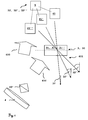
- the multiplex hologram 3 consists of a memory material with a plurality of interference patterns 31, 31 ', 31 ".
- the memory material is, for example, illuminated with an optical interference pattern 31, 31', 31" or printed with a digital interference pattern 31, 31 ', 31 " the provision of a multiplex hologram 3, such as the embossing of interference patterns 31, 31 ', 31 "in a memory material, etc. are also possible.
- FIG. 1 This is achieved by illuminating the memory material with an optical interference pattern 31, 31 ', 31 ".
- a coherent light source such as a helium neon laser, an argon laser, a neodymium laser diode, an arc or halogen lamp, etc. with a reference light wave
- the light source 4 generates a reference light wave 400 which is divided by a beam splitter 40.
- a part of the reference light wave 400 is directed to objects 41, 41 ', 41 "to be recorded, a part of the reference light wave 400 is directed to a light source 400 Hologram plane 30 of the multiplex hologram 3 steered.
- the reference light wave 400 is reflected by the objects 41, 41 ', 41 "and impinges on the hologram plane 30 as an object light wave 401 at an angle of incidence 32, 32', 32".
- the angle of incidence 32, 32 ', 32 " is the angle between the object light wave 401 and the normal of the hologram plane 30.
- the overlay of reference light wave 400 and object light wave 401 generates in the memory material a plurality of interference patterns 31, 31 ', 31 "as a function of the angles of incidence 32, 32', 32" of the object light wave 401 reflected at the objects 41, 41 ', 41 ".
- the number of interference patterns 31, 31 ', 31 "of the hologram plane 30 is limited by Bragg's equation
- Each object 41, 41', 41" is recorded at a unique angle of incidence 32, 32 ', 32 "
- the term “one-to-one” is used so that all angles of incidence 32, 32 ', 32 "differ from each other.
- the angular resolution increases with the thickness of the memory material. Therefore, so-called volume holograms are preferable in which a thickness of the storage material is larger than the wavelength of the light source 4.
- Digital printing patterns 31, 31 ', 31 are synthetically provided in a computer and written into the holographic storage material by a process similar to printing, but digital interference patterns 31, 31', 31" do not require physically real objects.
- Such multiplex holograms are inexpensive, the manufacturing costs are around 0.5 € per centimeter 2 .
- digital interference patterns 31, 31 ', 31 "and optical interference patterns 31, 31', 31” are equivalent.
- the interference patterns 31, 31 ', 31 "give an angle of incidence 32, 32 ', 32 "having at least one angular coordinate such as an azimuth angle coordinate ⁇ or a polar angle coordinate ⁇ .
- the interference patterns 31, 31', 31" can be provided at one or more wavelengths of the light source 4.
- interference patterns having a first wavelength may indicate the azimuth angle coordinate ⁇ of an angle of incidence
- interference patterns having a second wavelength different from the first one may indicate the polar angle coordinate ⁇ of this angle of incidence.
- the angular resolution of the multiplex hologram 3 is in the range of 0.1mrad to 1.0mrad, preferably 0.3mrad.
- the angular extent of the multiplex hologram 3 is 0.1 to nrad. With an angular resolution of 0.3 mrad and using, for example, 3333 identical interference patterns 31, 31 ', 31 ", the angle circumference is thus 1rad.
- At least one multiplex hologram 3 is arranged on the element 1.
- multiple multiplex holograms 3 can also be arranged on the first element 1, each of which covers a different angular range.
- a first multiplex hologram 3 covers an angular range of 0 to 1rad
- a second multiplex hologram 3 covers an angular range of 1 to 2rad
- a third multiplex hologram 3 covers an angular range of 2 to 3rad, etc.
- a corresponding incident angle 32, -32 ', 32 "of each object 41, 41', 41” is detected by an angle sensor 5.
- An angle signal 52, 52 ', 52 " is formed which comprises a pairing of the object 41, 41', 41” and its angles of incidence 32, 32 ', 32 ".
- the angle signal 52, 52', 52" can also contain further information such as Height and width of the bell curve Bragg intensity I of intensity patterns 61, 61 ', 61 ", etc.
- the angle signal 52, 52', 52" is computer-readable data stored.
- an information content of the object 41, 41 ', 41 "indicates the angle of incidence 32, 32', 32".
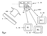
- FIG. 2 For this purpose, a multiplex hologram 3 with reference light wave 400 is illuminated, and a reference light wave 400 'diffracted by the interference pattern 31, 31', 31 "is output by a light detector 6 as an intensity pattern 61, 61 ', 61
- the reconstruction of the intensity pattern 61, 61 ', 61 "takes place as a function of the angle of incidence 32, 32', 32", ie the light detector 6 must be at the angle of incidence 32, 32 ', 32 "of an interference pattern 31, 31', 31 to the multiplex hologram 3 to detect an intensity pattern 61, 61 ', 61 ".
- the light source 4 can be operated continuously or pulsed. In a pulsed operation, a pulse width modulation can be carried out for the transmission of at least one additional information.
- the light source 4 transmits additional information such as the type of the multiplex hologram 3, the version of the interference patterns 31, 31 ', 31 ", an angle signal 52, 52', 52", an ambient temperature, etc. to the illumination of the multiplex hologram 3 with reference light wave 400 Light detector 6, which makes the process even clearer and more robust.
- the light source 4 advantageously has a broad band of wavelengths of light waves, of which the multiplex hologram 3 is at least one wavelength of a reference light wave 400 bends with high efficiency. For volume holograms, white light can be used.
- the light detector 6 has at least one sensor 60, 60 'such as a charge-coupled device (CCD) sensor or a complementary metal oxide semiconductor (CMOS) sensor.
- the light detector 6 detects the intensity pattern 61, 61 ', 61 "in a detector plane
- the light detector 6 detects at least the wavelength of the diffracted reference light source 400' and forms the intensity pattern 61, 61 ', 61".
- the light detector 6 may have filters to unambiguously form the intensity pattern 61, 61 ', 61 "using multiple wavelengths of the light source 4.
- the light detector 6 detects the diffracted reference light wave 400' based on the angular resolution given by Bragg's equation of the multiplex hologram 3 with different Bragg intensity I over a small angular range of the angle of incidence 32, 32 ', 32 ". That the light detector 6 can measure the detected Bragg intensity I within an angular range, for example, by summing up the detected photons per pixel of the sensor 60.
- the Bragg intensity I has approximately the shape of a bell curve, in the center of the angular range is the detected Bragg intensity I of the diffracted reference light wave 400 'maximum.
- FIGS. 3 to 6 show four exemplary embodiments of intensity patterns 61, 61 ', 61 ", which are largely identical to their underlying object 41, 41', 41". These are known opto-electronically readable bar codes.
- FIG. 3 Fig. 11 shows an intensity pattern 61, 61 ', 61 "in the embodiment of a two-dimensional codeclock F code having a plurality of lines of one-dimensional bar codes
- F-codes is standardized according to ISO / IEC 15417 of the International Organization for Standardization (ISO) and can have two to 44 lines.
- Each Codablock F-Code can be encoded up to 1Kbyte.
- FIG. 4 shows an intensity pattern 61, 61 ', 61 "in the embodiment of a two-dimensional DataMatrix code having a square or rectangular area as a pattern of square or round symbol elements.
- the DataMatrix code is normalized according to ISO / IEC 16022.
- Per DataMatrix code can be encoded more than 1Kbyte.
- FIG. 5 shows an intensity pattern 61, 61 ', 61 "in the embodiment of a two-dimensional maxi-code with hexagonal symbol elements and a central search pattern in the form of three concentric circles
- the search pattern is clearly visible and allows a clear centering of the light detector 6 and a correction of distortions in the detected
- the MaxiCode has a low information content of around 50 bytes, but the MaxiCode can be read very quickly and reliably thanks to the search pattern.
- FIG. 6 Figure 4 shows an intensity pattern 61, 61 ', 61 "in the embodiment of a two-dimensional quadratic symbol quadrature quick response code
- the Quick Response code is normalized according to the ISO / IEC 18004: 2006 standard and has synchronization marks in the corners of the matrix On, which allow a clear orientation of the intensity pattern, so that the beginning and end of the QuickResponse code are clearly detectable.
- the information content of the Quick Response code is very high and is just under 3KByte.
- intensity patterns not shown.
- symbol elements with eight, sixteen, and more different gray levels can be used, which further increases the information content of the intensity patterns.
- those skilled in the art can use intensity patterns with different sized symbol elements so that larger symbol elements of an intensity pattern can be clearly detected from a distance of several hundred meters, while smaller symbol elements of the intensity pattern can be clearly detected from a small distance of less than fifty meters.
- Fig. 7 1 shows a data communication between an angle sensor 5 with an evaluation unit 7 and / or between a light detector 6 and an evaluation unit 7.
- the angle sensor 5 transmits angle signals 52, 52 ', 52 "to the evaluation unit 7, and the light detector 6
- only the light detector 6 transmits intensity patterns 61, 61 ', 61 "to the evaluation unit 7.
- the instantaneous, in real time detected intensity patterns 61, 61', 61" are transmitted to the evaluation unit 7.
- the data communication is bidirectional and can be wired or wireless.
- Cable-based or radio-based data communication uses a protocol such as the Transmission Control Protocol / Internet Protocol (TCP / IP).
- Cable-based data communication takes place via a data bus such as Ethernet, USB, etc.
- Wireless data communication takes place via a radio network such as Enhanced Data Rate for GSM Evolution (EDGE), Asymetric Digital Subscriber Line (ADSL), Institute of Electrical and Electronics Engineers (IEEE) 802.11, etc.
- EDGE Enhanced Data Rate for GSM Evolution
- ADSL Asymetric Digital Subscriber Line
- IEEE Institute of Electrical and Electronics Engineers 802.11, etc.
- Both the angle sensor 5, the light detector 6 and the evaluation unit 7 have corresponding interfaces for data communication.
- the person skilled in the art can also execute the light detector with an evaluation unit integrated in the housing as a single unit.
- the evaluation unit 7 has a microprocessor and a computer-readable data memory.
- the computer program means is loaded from the computer-readable data memory of the evaluation unit 7 in the microprocessor of the evaluation unit 7 and executed.
- the evaluation unit 7 may be a stationary computer such as a personal computer (PC) or a mobile computer such as a laptop, smartphone, etc.
- the computer program means assigns to each transmitted intensity pattern 61, 61 ', 61 "a corresponding angle signal 52, 52', 52". For this purpose, the computer program means compares the bar code of an intensity pattern 61, 61 ', 61 "with those of the objects 41, 41', 41” in accordance with the angle signals 52, 52 ', 52 “. 61 ", the incident pattern 32, 32 ', 32" of the object 41, 41', 41 "according to angle signal 52, 52 ', 52" assigned.
- the computer program means reads out the information content of the two-dimensional bar code, which information content indicates the angle of incidence 32, 32 ', 32 ".
- the intensity pattern 61, 61', 61" this read-out angle of incidence 32, 32 ', 32 "is assigned.
- a multiplex hologram 3 is arranged on a first element 1 and the light detector 6 is arranged on a second element 2.
- the arbitrarily designed elements 1, 2 are spatially separated from each other, they may be less than a meter or several hundred meters apart.
- the multiplex hologram 3 is externally attached to the first element 1 or internally in the first element 1 such that the hologram plane 30 of the planar memory material is aligned in a known fixed spatial relationship to a first element plane 10 of the first element 1.
- the light detector 6 is externally attached to the second element 2 such that a detector plane of the light detector 6 is aligned in a known fixed spatial relationship to a second element plane 20 of the second element 2.
- the light detector 6 itself can also form the second element 2.
- a multiplex hologram 3 arranged on a first element 1 can be detected by a plurality of light detectors 6 arranged on second elements 2 such that an angle between the first element plane 10 and the second element plane 20 is calculated for each second element 2. This can be done independently of each other and with a time delay or at the same time.
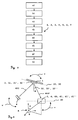
- FIG. 8 shows a flowchart of the method for measuring an angle between two spatially separated elements 1, 2, with the steps: a) providing a multiplex hologram 3 with a plurality of arranged in a hologram plane 30 interference patterns 31, 31 ', 31 ", at least two interference pattern 31, 31 ', 31 "have different angles of incidence 32, 32', 32" of an object light wave 401 the hologram plane 30, the angles of incidence 32, 32 ', 32 "of the interference patterns 31, 31', 31” are computer-readable data-stored; b) arranging the multiplex hologram 3 in a first element plane 10 on a first element 1; c) illuminating the multiplex hologram 3 with a reference light wave 400; d) arranging a light detector 6 in a second element plane 20 on a second element 2; e) detecting a reference light wave 400 diffracted at an interference pattern 31, 31 ', 31 "with the light detector 6; f) forming an intensity pattern 61, 61', 61
- FIGS. 9 to 12 show four exemplary embodiments of a system for carrying out the method.
- the system comprises the multiplex hologram 3, the light source 4, the light detector 6 and the evaluation device 7.
- the multiplex hologram 3 is arranged on the first element 1, the hologram plane 30 is congruent to the first element plane 10.
- the light detector 6 is arranged on the second element 2, the The detector plane is congruent with the second element plane 20.
- Coordinates of the second element plane 20 are indicated in a reference coordinate system K such as a polar coordinate system, a spherical coordinate system or an orthogonal coordinate system.
- An azimuth angle coordinate ⁇ and / or a polar angle coordinate ⁇ of the angle between the elements 1, 2 is measured.
- the reference coordinate system K may be a relative or absolute coordinate system.
- the intensity pattern 61, 61 ', 61 "becomes an angle of incidence
- the angle between the first element plane 10 and the second element plane 20 is calculated from the difference of the coordinates of the second element plane 20 and the coordinates of the associated angle of incidence 32, 32 ', 32 ". Coordinate ⁇ of the angle can be measured simultaneously.
- the person skilled in the art can arrange the multiplex hologram 3 at any known arrangement angle on the first element 1; the congruence of the hologram plane 30 to the first element level 10 is therefore not mandatory.
- the skilled person can arrange the light detector 6 at any known arrangement angle on the second element 2; also the congruence of the detector plane to the second element level 20 is not mandatory.
- the FIGS. 9 to 12 shows a multiplex hologram 3 in the embodiment of a reflection hologram that reflects the diffracted reference light wave 400 '.
- the multiplex hologram 3, the light source 4 and the light detector 6 form components of a system.
- placeable means any spatial placement of the component of the system in the reference coordinate system.
- alignable is understood to mean any orientation of the component of the system in the reference coordinate system. Specifically, however, always one of these components of the system is variably arranged and two of these components of the system are fixed and fixed Orientation arranged relative to each other. This is the basic embodiment of the invention. This spatially variable alignment and placement is limited by the angular extent of the multiplex hologram 3.
- the light detector 6 is spatially variably placeable and alignable, as shown by the arrow v.
- the light source 4 illuminates the multiplex hologram 3 at a constant reference light angle.
- the light source 4 and the laser detector 6 are mechanically connected to each other and fixedly arranged, which is represented by a designated f line. Only the multiplex hologram 3 is spatially variably placeable and alignable, as shown by the arrow v.
- the light source 4 illuminates the multiplex hologram 3 at a constant reference light angle
- the light detector 6 detects the diffracted reference light wave 400 'at a variable light detector angle, since the multiplex hologram 3 is spatially variably placeable and alignable.
- FIG. 12 shows a multiplex hologram 3 in the embodiment of a transmission hologram that transmits the diffracted reference light wave 400 '.
- the light detector 6 is arranged stationary, which is represented by a designated T-carrier.
- the light source 4 is mechanically connected to the multiplex hologram 3, which is represented by a line denoted by f.
- light source 4 and multiplex hologram 3 are spatially variably spatially placeable and alignable, as shown by the arrow v.
- the light source 4 illuminates the multiplex hologram 3 under a constant reference light angle.
- a diffracted reference light wave 400 'in the reference coordinate system K is detected by the light detector 6 in function of the azimuth angle coordinate ⁇ , and an intensity pattern 61 in the embodiment of a bar code is detected.
- Deviation of the spatial orientation of the two-dimensional bar code to the reference coordinate system K is measured as the roll angle ⁇ 'of the light detector 6.
- the roll angle is a tilting of the detector plane of the light detector 6 with respect to the second element plane 20.
- the roll angle ⁇ ' is another degree of freedom in measuring the angle between the two elements 1, 2nd
- a distortion of the intensity pattern 61, 61', 61 ' can be detected, for example, when an intensity pattern 61, 61', 61 'in the embodiment a MaxiCode after FIG. 5 an elliptically distorted search pattern, while the corresponding maxi-code of the object 41, 41 ', 41 "has a circular search pattern, and an angle between the first element 1 and the second element 2 can be measured very quickly from the magnitude and direction of such distortion
- the pattern may also be distorted differently, so the distortion may be square, trapezoidal, etc.
- FIGS. 14 to 17 10 show several embodiments of detecting a diffracted reference light wave 400 'with the light detector 6 and forming the intensity pattern 61, 61', 61 ".
- the light detector 6 may detect the detected Bragg intensity I within an angular range, for example by summing the detected photons per pixel of the sensor 60.
- the Bragg intensity I varies over the angular spacing of an intensity pattern 61, 61 ', 61 "and is approximately in the form of a bell curve, in the center of the angular range the detected Bragg intensity I of the diffracted reference light wave 400' is at most the height and width of the bell curve of FIG Bragg intensity I of the intensity patterns 61, 61 ', 61 "formed from the detected diffracted reference light wave 400' can be determined and thus beforehand known and computer-readable data stored.
- the variation of the detected Bragg intensity I with the detection angle can be used for a more accurate determination of the angular resolution of the intensity pattern 61, 61 ', 61 " diffracted reference light wave 400 'formed intensity pattern 61, 61', 61 "with a higher angular resolution than an angular distance of the intensity pattern 61, 61 ', 61" determined.
- the angle of incidence 32, 32 ', 32 can be assigned as a function of the height and width of the bell curve of the Bragg intensity I with a fine angular resolution to the intensity pattern 61, 61', 61". This fine angular resolution of the system can be increased by about a factor of ten.
- the intensity pattern 61, 61 ', 61 is computer-readable data storage.
- the intensity pattern 61 has a gray wedge 63, which is detected with different Bragg intensity I depending on the azimuth angle coordinate .theta.
- the light detector 6 measures the detected Bragg intensity I of the gray wedge 63 at different positions P in the intensity pattern 61 and compares the measured Bragg intensity I of the gray wedge 63 with a predefined threshold value 63 '.
- the position in the An intensity pattern in which the gray wedge 63 exceeds the threshold value 63 ' is proportional to the Bragg intensity I and thus provides information about the deviation of the angle from the angle with the maximum Bragg intensity I.
- a diffracted reference light wave 400 ' is detected in the reference coordinate system K in function of the azimuth angle coordinate ⁇ .
- the detected Bragg intensity I of the diffracted reference light wave 400 ' is variable, in the center of the angular range it is maximum, which is in the FIGS. 15 to 17 represented by an intensity curve.
- one of the detected diffracted reference lightwave 400 'intensity pattern 61 is the most intense, which is represented by a dark bar code at the center of the angle range, two bar codes outside the center are shown comparatively brighter.
- the multiplex hologram 3 detects an arrangement of interference patterns 31, 31 ', 31 " FIG. 1 on. For different azimuth angle coordinates ⁇ different intensity patterns 61, 61 'are detected. At maximum Bragg intensity I, only a single intensity pattern 61, 61 'is imaged. In the transition between two intensity patterns 61, 61 'of adjacent azimuth angle coordinates ⁇ , the Bragg intensity I of the diffracted reference light wave 400' is lower and two intensity patterns 61, 61 'are imaged.
- FIG. 17 detects a light detector 6 with two sensors 60, 60 ', the diffracted reference light wave 400'.
- the two sensors 60, 60 'of the light detector 6 are largely identical and are in a known fixed spatial intersensor distance to each other.
- the two sensors 60, 60 'in the inter-sensor distance of 1/3 of the angular range of the Bragg-intensive angular resolution of the multiplex hologram 3 are arranged to each other.
- the diffracted reference light wave 400 'intensity pattern 61 in the embodiment of a bar code is shown comparatively brighter in the center of the angular range at the most intense and out of the center.
- the difference in the determined brightness can be used to determine the angle with higher accuracy.
- the distance is greater than the angular range of the Bragg angular resolution.
- both detectors receive different intensity patterns corresponding to different angles with respect to the multiplex hologram 3.
- a distance between the first element 1 and the second element 2 can be easily calculated from the angle of incidence 32, 32 ', 32 "and the intersensor distance.
- the system can be combined with an existing device for electronic distance measurement (EDM), in which a distance between the first element 1 and the second element 2 is measured by transit time measurement or phase shift of electromagnetic or acoustic waves.
- EDM electronic distance measurement
- the accuracy of the EDM is at geodesic distances in the mm range.
- the changing spatial orientation of the mobile device's multiplex hologram 3 is detected by the second element 2 by illuminating the multiplex hologram 3 with reference light wave 400 'and the light detector 6 detects the reference light wave 400 diffracted at the interference pattern 31, 31', 31 "and an intensity pattern 61, 61 ', 61 ".
- the angle between the first element plane 10 and the second element plane 20 can be calculated.
- the multiplex hologram 3 of the probe device may be flat or curved. Multiple multiplex holograms 3, four, six, eight, ten, or more multiplex holograms 3 may be mounted on the stylus to facilitate illuminating a multiplex hologram 3 and detecting diffracted reference lightwave 400 'from as many different spatial orientations of the probe as possible.
- the multiplex hologram 3 can also be attached to other mobile three-dimensional measuring instruments such as Cognitens TM OptiGo, Cognitens TM OptiCell, Cognitens TM WLS400, etc.
- At least one multiplex hologram 3 is attached to a construction machine such as an excavator, a loader, a caterpillar, a grader, etc.
- the first element 1 is designed as a construction machine.
- the person skilled in the art can also attach the multiplex hologram 3 to a component of a construction machine, such as a joint, a tool, etc.
- At least one multiplex hologram 3 is fixedly attached to a static object such as a wall, a mast, a survey pole, and so on.
- the first element 1 is executed as a static object.
- a location determination of the second element 2 takes place by means of backward slicing.
- the second element 2 is a mobile measuring device such as a scanner, tracker, rotating laser, total station, etc.
- the multiplex hologram 3 of the static object may be planar or curved; Thus, it may include the circumference of an outer surface of a surveying rod in parts or completely.
- the multiplex hologram 3 of the static object can be used outdoors and indoors for both terrestrial surveying and airborne surveying.
- the multiplex hologram 3 can be indirectly targeted directly or via prisms to measure a hidden target point.
- a system with at least one multiplex hologram 3, a light source 4, a light detector 6 and an evaluation unit 7 is used as an angle encoder.
- the multiplex hologram 3 is attached to a first element 1 in the design of a dynamic object such as a joint, articulated arm, robotic arm, etc.
- the multiplex hologram 3 may be flat or curved.
- At least one multiplex hologram 3 is attached to a coordinate measuring machine.
- the first element 1 is designed as a coordinate measuring machine.
- At least one camera such as a single camera or a stereo camera, monitors the multiplex hologram 3.
- the camera corresponds to the second element 2.
- the changing spatial orientation of the multiplex hologram 3 of the probe device is detected by the second element 2 by illuminating the multiplex hologram 3 with reference light wave 400 'and the light detector 6 diffracting the interference pattern 31, 31', 31 " Reference light wave 400 'detected and formed an intensity pattern 61, 61', 61 ".
- the intensity pattern 61, 61 ', 61 is assigned an angle of incidence 32, 32', 32".
- the coordinate measuring machine can be monitored at short notice or in the long term. During a short-term monitoring of changing angles of incidence 32, 32 ', 32 "deformations in the operation of the coordinate measuring machine determined, so can be determined by the Detecting startup dynamics in real time and eliminate them. In the case of long-term monitoring, changing angles of incidence 32, 32 ', 32 "of material fatigue during operation of the coordinate measuring machine are determined.
- At least one multiplex hologram 3 is attached to a reference object of a coordinate measuring machine.
- the calibration object may be a reference element, a measuring table, etc.
- the first element 1 is designed as a calibration object.
- the spatial orientation of the multiplex hologram 3 is detected by the second element 2 by illuminating the multiplex hologram 3 with the reference light wave 400 'and the light detector 6 detects the reference light wave 400' diffracted at the interference patterns 31, 31 ', 31 "and an intensity pattern 61, 61 ', 61 "formed.
- the intensity pattern 61, 61 ', 61 is assigned at least one angle of incidence 32, 32', 32".
- the second element 2 is moved in a calibration position until the associated angle of incidence 32, 32 ', 32 "corresponds to a predefined calibration angle.
Description
Die Erfindung betrifft ein Verfahren zum Messen eines Winkels zwischen zwei räumlich voneinander entfernten Elementen nach dem unabhängigen Anspruch 1.The invention relates to a method for measuring an angle between two spatially mutually remote elements according to
Das Bestimmen von Winkeln und Richtungen ist in vielen Anwendungsbereichen wie der Geodäsie, im Hoch- und Tiefbau, der industriellen Automationstechnik, usw. gefordert. Dabei werden hohe Ansprüche an die Messgenauigkeit, die Messgeschwindigkeit und den Grad der Verfügbarkeit, und all dies auch unter rauen Umweltbedingungen, gestellt.Determining angles and directions is required in many applications such as geodesy, civil engineering, industrial automation, and so on. High demands are placed on the measuring accuracy, the measuring speed and the degree of availability, and all this even under harsh environmental conditions.
Die
Die beiden Elemente sind räumlich über eine Distanz von beispielsweise 100m voneinander entfernt. Das erste Element weist einen Code-Träger auf, das zweite Element weist einen Code-Leser mit dem Code-Leser nachgeordneten Rechner auf. Der Code-Leser erfasst ein eindimensionales Code-Muster des Code-Trägers und übermittelt für ein erfasstes Code-Muster ein Code-Signal an den Rechner. Der Rechner weist Mittel zur Quantisierung des übermittelten Code-Signals und zum Vergleich mit einem gespeicherten Code-Muster sowie zur Errechnung der Relativposition zwischen dem ersten Element und dem zweiten Element aus dem Ergebnis des Vergleichs auf.The two elements are spatially separated over a distance of, for example, 100m. The first element has a code carrier, the second element has a code reader with the code reader downstream computer. The code reader acquires a one-dimensional code pattern of the code carrier and transmits a code signal to the computer for a detected code pattern. The computer has means for quantizing the transmitted code signal and for comparison with a stored code pattern and for calculating the relative position between the first element and the second element from the result of the comparison.
Die Aufgabe der Erfindung besteht darin, ein verbessertes Verfahren zum Messen eines Winkels zwischen zwei räumlich voneinander entfernten Elementen bereitzustellen.The object of the invention is to provide an improved method for measuring an angle between two spatially separated elements.
Die Aufgabe wird durch die Merkmale des unabhängigen Anspruchs 1 gelöst.The object is solved by the features of
Erfindungsgemäß weist das Verfahren zum Messen eines Winkels zwischen zwei räumlich voneinander entfernten Elementen, die Schritte auf: a) Bereitstellen eines Multiplexhologramms mit mehreren Interferenzmustern, mindestens zwei Interferenzmuster weisen unterschiedliche Einfallswinkel einer Objektlichtwelle auf eine Hologrammebene auf, die Einfallswinkel sind computerlesbar datengespeichert; b) Anordnen des Multiplexhologramms in einer ersten Elementebene an einem ersten Element; c) Beleuchten des Multiplexhologramms mit einer Referenzlichtwelle; d) Anordnen eines Lichtdetektors in einer zweiten Elementebene an einem zweiten Element; e) Erfassen einer an einem Interferenzmuster gebeugten Referenzlichtwelle mit dem Lichtdetektor; f) Bilden eines Intensitätsmusters aus der erfassten gebeugten Referenzlichtwelle; g) Zuordnen des computerlesbar datengespeicherten Einfallswinkels zum Intensitätsmuster; und h) Berechnen eines Winkels zwischen der ersten Elementebene und der zweiten Elementebene aus dem zugeordneten Einfallswinkel.According to the invention, the method for measuring an angle between two spatially mutually remote elements comprises the steps of: a) providing a multiplex hologram with a plurality of interference patterns, at least two interference patterns have different angles of incidence of an object light wave to a hologram plane, the angles of incidence are computer-readable data-stored; b) arranging the multiplex hologram in a first element plane on a first element; c) illuminating the multiplex hologram with a reference light wave; d) arranging a light detector in a second element plane on a second element; e) detecting a reference light wave diffracted at an interference pattern with the light detector; f) forming an intensity pattern from the detected diffracted reference light wave; g) assigning the computer readable data stored angle of incidence to the intensity pattern; and h) calculating an angle between the first element plane and the second element plane from the associated angle of incidence.
In der vorliegenden Erfindung wird unter einem Intensitätsmuster eine flächenhaft ausgedehnte Anordnung einer Vielzahl von Formen, z.B. Quadrate oder Linien, verstanden, die eine vom Hintergrund, auf dem sie platziert sind, unterscheidbare Eigenschaft aufweisen. Eine solche Eigenschaft ist der Helligkeitswert, der Farbwert u.a. Ausgeprägt ist ein solches Intensitätsmuster bspw. als eine Anordnung von 500 schwarzen Quadraten, die sich teilweise berühren können, auf einer hellen Rechtecksfläche als Hintergrund, wodurch eine eindeutig identifizierbare Struktur vorliegt. Insbesondere beinhaltet ein solches Muster einen Informationsgehalt in Form eines maschinenlesbaren Codes. Erfindungsgemäss wird der Begriff "Code" als Abbildung von Daten mittels binärer Symbolelemente verstanden, bspw. ein Strichcode.In the present invention, under an intensity pattern, an areally extended arrangement of a plurality of shapes, e.g. Squares or lines understood to have a distinguishable property from the background on which they are placed. Such a property is the brightness value, the color value u.a. Such an intensity pattern, for example, is pronounced as an arrangement of 500 black squares, which can partially touch, on a light rectangle surface as the background, thereby providing a clearly identifiable structure. In particular, such a pattern contains an information content in the form of a machine-readable code. According to the invention, the term "code" is understood as an illustration of data by means of binary symbol elements, for example a bar code.
Mit einem Multiplexhologramm lässt sich in an sich bekannter Weise ein winkelaufgelöstes Intensitätsmuster aus einer gebeugten Referenzlichtwelle rekonstruieren. Dabei ist nur für jeweils einen diskreten Einfallswinkel der Referenzlichtwelle jeweils ein Intensitätsmuster mit maximaler Intensität rekonstruierbar. Es hat sich nun herausgestellt, dass sich diese Winkelauflösung auch beim Messen eines Winkels zwischen zwei räumlich voneinander entfernten Elementen praktisch anwenden lässt. Unter Berücksichtigung des Informationsgehalts des Intensitätsmusters lässt sich nämlich dem Intensitätsmuster sehr schnell und in eineindeutiger Weise ein Einfallswinkel einer Objektlichtwelle auf die Hologrammebene des Multiplexhologramms zuordnen. Aufgrund der nicht-kontinuierlichen Winkelverteilung ergibt sich eine unstetige -quasi digitale- Zuordnung von Einfallswinkeln und Intensitätsmustern. Die Zuordnung erfolgt dabei aufgrund des Informationsgehalts eines Musters. Aus der räumlichen Ausrichtung der Hologrammebene bezüglich eines ersten Elements sowie aus der räumlichen Ausrichtung des die gebeugte Referenzlichtwelle erfassenden Lichtdetektors bezüglich eines zweiten Elements lässt sich unter Verwendung bestehender, bewährter und robuster Techniken der Geodäsie bzw. der industriellen Vermessungstechnik ein Winkel zwischen dem ersten Element und dem zweiten Element berechnen. Eine verfeinerte Winkelbestimmung kann erfindungsgemäss u.a. erreicht werden, indem zusätzlich die Stärke der Intensität eines Intensitätsmusters erfasst wird, da sich auch innerhalb eines gewissen Winkelbereichs um den jeweiligen Einfallswinkel noch von der Maximalintensität unterschiedene Intensitäten erfassen lassen. Durch den Vergleich mit der bekannten Maximalintensität ist eine Abweichung vom diskreten Einfallswinkel quantifizierbar. Bei einer ausreichend grossen Anzahl an unabhängigen Interferenzmustern ergibt sich eine Anordnung von Intensitätsmustern, die dicht genug ist, um eine quasi-kontinuierliche Winkelauflösung zu erhalten.With a multiplex hologram, an angle-resolved intensity pattern from a diffracted reference light wave can be reconstructed in a manner known per se. In each case, an intensity pattern with maximum intensity can only be reconstructed for a respective discrete angle of incidence of the reference light wave. It has now been found that this angular resolution can also be practically applied when measuring an angle between two spatially separated elements. In fact, taking into account the information content of the intensity pattern, it is possible to very quickly and unambiguously associate the intensity pattern with an angle of incidence of an object light wave onto the hologram plane of the multiplex hologram. Due to the non-continuous angular distribution results in a discontinuous -quasi digital- assignment of angles of incidence and intensity patterns. The assignment is based on the information content of a pattern. From the spatial orientation of the hologram plane with respect to a first element as well as from the spatial orientation of the light detector detecting the diffracted reference light wave with respect to a second element can be made using existing, proven and robust techniques of geodesy or industrial surveying an angle between the first element and the calculate second element. A refined angle determination can be achieved according to the invention, inter alia, by additionally detecting the strength of the intensity of an intensity pattern, since it is also possible to detect intensities differing from the maximum intensity within a certain angular range around the respective angle of incidence. By comparison with the known maximum intensity, a deviation from the discrete angle of incidence can be quantified. Given a sufficiently large number of independent interference patterns, an array of intensity patterns results which is dense enough to obtain a quasi-continuous angular resolution.
Vorteilhafte Weiterbildungen der Erfindung ergeben sich aus den Merkmalen der abhängigen Ansprüche.Advantageous developments of the invention will become apparent from the features of the dependent claims.
Vorteilhafterweise werden Koordinaten der zweiten Elementebene in einem Bezugskoordinatensystem angegeben; Koordinaten des zugeordneten Einfallswinkels werden im Bezugskoordinatensystem angegeben; und im Schritt h) wird der Winkel aus der Differenz der Koordinaten der zweiten Elementebene und der Koordinaten des zugeordneten Einfallswinkels berechnet.Advantageously, coordinates of the second element plane are specified in a reference coordinate system; Coordinates of the assigned angle of incidence are indicated in the reference coordinate system; and in step h) the angle is calculated from the difference of the coordinates of the second element plane and the coordinates of the associated angle of incidence.
Da das Multiplexhologramm in einer bekannten festen räumlichen Beziehung zur ersten Elementebene des ersten Elements angeordnet ist, und der Lichtdetektor ebenfalls in einer bekannten festen räumlichen Beziehung zur zweiten Elementebene des zweiten Elements angeordnet ist, reicht es somit aus, die Koordinaten der zweiten Elementebene und die Koordinaten des zugeordneten Einfallswinkels in ein und demselben Bezugskoordinatensystem anzugeben, um den Winkel einfach und eindeutig zu berechnen.Because the multiplex hologram is in a known fixed spatial relationship to the first element plane of the first element is arranged, and the light detector is also arranged in a known fixed spatial relationship to the second element plane of the second element, it is thus sufficient to specify the coordinates of the second element plane and the coordinates of the associated angle of incidence in one and the same reference coordinate system, the angle and simple to calculate clearly.
Weitere Vorteile und Merkmale der Erfindung sind aus der folgenden Beschreibung von derzeit bevorzugten Ausführungsformen im Zusammenhang mit den anhängenden Figuren beispielhaft ersichtlich:
-
Figur 1 -
Figur 2Figur 1 -
Figur 3Figur 12 ; -
Figur 4Figur 12 ; -
Figur 5Figur 12 ; -
Figur 6Figur 12 ; -
Figur 7Figur 1Figur 2 -
Figur 8 zeigt ein Flussdiagramm der Schritte des Verfahrens; -
Figur 9 zeigt einen Teil einer ersten Ausführungsform eines Systems zum Durchführen des Verfahrens nachFigur 8 mit einem Multiplexhologramm nachFigur 12 ; -
Figur 10Figur 8 mit einem Multiplexhologramm nachFigur 12 ; -
Figur 11 zeigt einen Teil einer dritten Ausführungsform eines Systems zum Durchführen des Verfahrens nachFigur 8 mit einem Multiplexhologramm nachFigur 12 ; -
Figur 12 zeigt einen Teil einer vierten Ausführungsform eines Systems zum Durchführen des Verfahrens nachFigur 8 mit einem Multiplexhologramm nachFigur 12 ; -
Figur 13 zeigt einen Teil einer ersten Ausführungsform eines Lichtdetektors zum Durchführen des Verfahrens nachFigur 8 , mit einem Intensitätsmuster, das einen Rollwinkel aufweist; -
Figur 14 zeigt einen Teil einer zweiten Ausführungsform eines Lichtdetektors zum Durchführen des Verfahrens nachFigur 8 , mit Graustufenkeil im Intensitätsmuster; -
Figur 15 zeigt einen Teil einer dritten Ausführungsform eines Lichtdetektors zum Durchführen des Verfahrens nachFigur 8 , mit einem Intensitätsmuster, das bei unterschiedlichen Winkeln und damit mit unterschiedlichen Bragg-Intensitäten erfasst wird; -
Figur 16 zeigt einen Teil einer vierten Ausführungsform eines Lichtdetektors zum Durchführen des Verfahrens nachFigur 8 , mit zwei Intensitätsmuster, die mit maximaler Bragg-Intensität erfasst werden; und -
Figur 17 zeigt einen Teil einer fünften Ausführungsform eines Lichtdetektors mit zwei Sensoren zum Durchführen des Verfahrens nachFigur 8 .
-
FIG. 1 shows a part of a first embodiment of a multiplex hologram with a plurality of interference patterns; -
FIG. 2 shows a part of the embodiment of a multiplex hologram afterFIG. 1 upon detecting an intensity pattern; -
FIG. 3 shows a part of a first embodiment of an intensity pattern of a multiplex hologram afterFIG. 1 and2 ; -
FIG. 4 shows a part of a second embodiment of an intensity pattern of a multiplex hologram afterFIG. 1 and2 ; -
FIG. 5 shows a part of a third embodiment of an intensity pattern of a multiplex hologramFIG. 1 and2 ; -
FIG. 6 shows a part of a fourth embodiment of an intensity pattern of a multiplex hologram afterFIG. 1 and2 ; -
FIG. 7 shows an angle sensorFIG. 1 and / or a light detectorFIG. 2 in data communication with a part of an embodiment of an evaluation unit; -
FIG. 8 shows a flowchart of the steps of the method; -
FIG. 9 shows a part of a first embodiment of a system for carrying out the methodFIG. 8 with a multiplex hologram afterFIG. 1 and2 ; -
FIG. 10 shows a part of a second embodiment of a system for carrying out the method according toFIG. 8 with a multiplex hologram afterFIG. 1 and2 ; -
FIG. 11 shows a part of a third embodiment of a system for carrying out the methodFIG. 8 with a multiplex hologram afterFIG. 1 and2 ; -
FIG. 12 shows a part of a fourth embodiment of a system for carrying out the methodFIG. 8 with a multiplex hologram afterFIG. 1 and2 ; -
FIG. 13 shows a part of a first embodiment of a light detector for performing the method according toFIG. 8 with an intensity pattern having a roll angle; -
FIG. 14 shows a part of a second embodiment of a light detector for performing the method according toFIG. 8 , with grayscale wedge in intensity pattern; -
FIG. 15 shows a part of a third embodiment of a light detector for performing the method according toFIG. 8 with an intensity pattern detected at different angles and thus with different Bragg intensities; -
FIG. 16 shows a part of a fourth embodiment of a light detector for performing the method according toFIG. 8 , with two intensity patterns detected at maximum Bragg intensity; and -
FIG. 17 shows a part of a fifth embodiment of a light detector with two sensors for performing the method according toFIG. 8 ,
Das Multiplexhologramm 3 besteht aus einem Speichermaterial mit mehreren Interferenzmustern 31, 31', 31". Das Speichermaterial wird beispielsweise mit einem optischen Interferenzmuster 31, 31', 31" beleuchtet oder mit einem digitalen Interferenzmuster 31, 31', 31" bedruckt. Andere Arten des Bereitstellens eines Multiplexhologramms 3, wie das Prägen von Interferenzmustern 31, 31', 31" in ein Speichermaterial, usw. sind ebenfalls möglich.The
Die Anzahl der Interferenzmuster 31, 31', 31" der Hologrammebene 30 ist durch die Bragg'sche Gleichung beschränkt. Jedes Objekt 41, 41', 41" wird unter einem eineindeutigen Einfallswinkel 32, 32', 32" aufgezeichnet. Im Verständnis der vorliegenden Erfindung wird der Begriff "eineindeutig" so verwendet, dass sich alle Einfallswinkel 32, 32', 32" voneinander unterscheiden. Nach der Bragg'schen Gleichung steigt die Winkelauflösung mit der Dicke des Speichermaterials. Daher sind so genannte Volumenhologramme zu bevorzugen, bei denen eine Dicke des Speichermaterials größer als die Wellenlänge der Lichtquelle 4 ist. In einer Volumeneinheit des Multiplexhologramm 3 lassen sich mehrere zehn Interferenzmuster 31, 31', 31", vorzugsweise mehrere hundert Interferenzmuster 31, 31', 31", vorzugsweise mehrere tausend Interferenzmuster 31, 31', 31" überlagern und einzeln auslesen.The number of
Im figürlich nicht dargestellten Drucken von digitalen Interferenzmustern werden digitale Interferenzmuster 31, 31', 31" in einem Computer synthetisch bereitgestellt und durch einem dem Drucken ähnlichen Verfahren in das holografische Speichermaterial geschrieben. Digitale Interferenzmuster 31, 31', 31" benötigen somit keine physikalisch reellen Objekte. Solche Multiplexhologramme sind kostengünstig, die Herstellkosten betragen rund 0.5€ pro Zentimeter2. Von der Funktion her sind digitale Interferenzmuster 31, 31', 31" und optische Interferenzmuster 31, 31', 31" gleichwertig.
Die Interferenzmuster 31, 31', 31" geben einen Einfallswinkel 32, 32', 32" mit mindestens einer Winkelkoordinate an, wie eine Azimutwinkel-Koordinate θ oder eine Polarwinkel-Koordinate ϕ. Die Interferenzmuster 31, 31', 31" lassen sich mit einer Wellenlänge oder mit mehreren Wellenlängen der Lichtquelle 4 bereitstellen. So können zum Beispiel Interferenzmuster mit einer ersten Wellenlänge die Azimutwinkel-Koordinate θ eines Einfallswinkels angeben und Interferenzmuster mit einer zweiten, von der ersten verschiedenen Wellenlänge können die Polarwinkel-Koordinate ϕ dieses Einfallswinkels angeben.The
Für ein Speichermaterial von einem bis mehrere Millimeter Dicke liegt die Winkelauflösung des Multiplexhologramms 3 gemäß der Bragg'schen Gleichung im Bereich von 0.1mrad bis 1.0mrad, vorzugsweise bei 0.3mrad. Der Winkelumfang des Multiplexhologramms 3 beträgt 0.1rad bis nrad. Bei einer Winkelauflösung von 0.3mrad und unter Verwendung von beispielsweise 3333 gleichartigen Interferenzmustern 31, 31', 31" beträgt der Winkelumfang somit 1rad.For a storage material of one to several millimeters thickness, the angular resolution of the
Mindestens ein Multiplexhologramm 3 ist am Element 1 angeordnet. Bei Kenntnis der vorliegenden Erfindung lassen sich natürlich auch mehrere Multiplexhologramme 3 am ersten Element 1 anordnen, von denen jedes einen anderen Winkelbereich abdeckt. Beispielsweise deckt ein erstes Multiplexhologramm 3 einen Winkelbereich von 0 bis 1rad ab, ein zweites Multiplexhologramm 3 deckt einen Winkelbereich von 1 bis 2rad ab, ein drittes Multiplexhologramm 3 deckt einen Winkelbereich von 2 bis 3rad ab, usw..At least one
Für das Bereitstellen eines solchen winkelaufgelösten Multiplexhologramms 3 wird von jedem Objekt 41, 41', 41" ein entsprechender Einfallswinkel 32,-32', 32" von einem Winkelaufnehmer 5 erfasst. In einer ersten Variante des Verfahrens wird ein Winkelsignal 52, 52', 52" gebildet, das eine Paarung des Objekts 41, 41', 41" und dessen Einfallswinkel 32, 32', 32" umfasst. Das Winkelsignal 52, 52', 52" kann auch weitere Informationen wie Höhe und Breite der Glockenkurve der Bragg-Intensität I von Intensitätsmustern 61, 61', 61", usw. umfassen. Das Winkelsignal 52, 52', 52" wird computerlesbar datengespeichert. In einer zweiten Variante des Verfahrens gibt ein Informationsgehalt des Objekts 41, 41', 41" den Einfallswinkel 32, 32', 32" an.For providing such an angle-resolved
Die Lichtquelle 4 kann kontinuierlich oder gepulst betrieben werden. Bei einem Pulsbetrieb kann eine Pulsweitenmodulation zur Übertragung von mindestens einer Zusatzinformation erfolgen. Die Lichtquelle 4 überträgt mit dem Beleuchten des Multiplexhologramms 3 mit Referenzlichtwelle 400 eine Zusatzinformation wie der Typ des Multiplexhologramms 3, die Version der Interferenzmuster 31, 31', 31", ein Winkelsignal 52, 52', 52", eine Umgebungstemperatur, usw. zum Lichtdetektor 6, was das Verfahren noch eindeutiger und robust macht. Die Lichtquelle 4 weist vorteilhafterweise ein breites Band von Wellenlängen von Lichtwellen auf, von denen das Multiplexhologramm 3 zumindest eine Wellenlänge einer Referenzlichtwelle 400 mit hohem Wirkungsgrad beugt. Bei Volumenhologrammen kann Weißlicht verwendet werden.The
Der Lichtdetektor 6 weist mindestens einen Sensor 60, 60' wie einen Charge-Coupled Device (CCD) Sensor oder einen Complementary Metal Oxide Semiconductor (CMOS) Sensor auf. Der Lichtdetektor 6 erfasst das Intensitätsmuster 61, 61', 61" in einer Detektorebene. Der Lichtdetektor 6 erfasst mindestens die Wellenlänge der gebeugten Referenzlichtquelle 400' und bildet das Intensitätsmuster 61, 61', 61". Der Lichtdetektor 6 kann Filter aufweisen, um das Intensitätsmuster 61, 61', 61" bei Verwendung von mehreren Wellenlängen der Lichtquelle 4 in eindeutiger Weise zu bilden. Der Lichtdetektor 6 erfasst die gebeugte Referenzlichtwelle 400' aufgrund der durch die Bragg'schen Gleichung vorgegebenen Winkelauflösung des Multiplexhologramms 3 mit unterschiedlicher Bragg-Intensität I über einen kleinen Winkelbereich des Einfallswinkels 32, 32', 32". D.h. der Lichtdetektor 6 kann die erfasste Bragg-Intensität I innerhalb eines Winkelbereichs beispielsweise durch Aufsummieren der erfassten Photonen je Pixel des Sensors 60 messen. Die Bragg-Intensität I hat etwa die Form einer Glockenkurve, im Zentrum des Winkelbereichs ist die erfasste Bragg-Intensität I der gebeugten Referenzlichtwelle 400' maximal.The
Die
Bei Kenntnis der vorliegenden Erfindung lassen sich andere, nicht dargestellte Intensitätsmuster verwenden. So lassen sich nicht nur Intensitätsmuster mit schwarzen und weißen Symbolelementen verwenden, sondern es lassen sich auch Symbolelemente mit acht, sechzehn, und mehr verschiedenen Graustufen verwenden, was den Informationsgehalt der Intensitätsmuster weiter erhöht. Auch kann der Fachmann Intensitätsmuster mit unterschiedlich großen Symbolelementen verwenden, so dass größere Symbolelemente eines Intensitätsmusters aus großer Entfernung von mehreren hundert Metern eindeutig erfassbar sind, während kleinere Symbolelemente des Intensitätsmusters aus kleiner Entfernung von weniger als fünfzig Metern eindeutig erfassbar sind.With knowledge of the present invention, other Use intensity patterns not shown. Thus, not only intensity patterns with black and white symbol elements can be used, but also symbol elements with eight, sixteen, and more different gray levels can be used, which further increases the information content of the intensity patterns. Also, those skilled in the art can use intensity patterns with different sized symbol elements so that larger symbol elements of an intensity pattern can be clearly detected from a distance of several hundred meters, while smaller symbol elements of the intensity pattern can be clearly detected from a small distance of less than fifty meters.
Die Datenkommunikation ist bidirektional und kann kabelgestützt oder funkgestützt erfolgen. Bei kabelgestützter oder funkgestützter Datenkommunikation wird ein Protokoll wie das Transmission Control Protocol/Internet-Protokoll (TCP/IP) verwendet. Kabelgestützte Datenkommunikation erfolgt über einen Datenbus wie Ethernet, USB, usw.. Funkgestützte Datenkommunikation erfolgt über ein Funknetz wie Enhanced Data Rate for GSM Evolution (EDGE), Asymetric Digital Subscriber Line (ADSL), Institute of Electrical and Electronics Engineers (IEEE) 802.11, usw.. Sowohl der Winkelaufnehmer 5, der Lichtdetektor 6 als auch die Auswerteeinheit 7 weisen entsprechende Schnittstellen für die Datenkommunikation auf. Bei Kenntnis der vorliegenden Erfindung kann der Fachmann auch den Lichtdetektor mit im Gehäuse integrierter Auswerteeinheit als eine einzige Einheit ausführen.The data communication is bidirectional and can be wired or wireless. Cable-based or radio-based data communication uses a protocol such as the Transmission Control Protocol / Internet Protocol (TCP / IP). Cable-based data communication takes place via a data bus such as Ethernet, USB, etc. Wireless data communication takes place via a radio network such as Enhanced Data Rate for GSM Evolution (EDGE), Asymetric Digital Subscriber Line (ADSL), Institute of Electrical and Electronics Engineers (IEEE) 802.11, etc. Both the
Die Auswerteeinheit 7 weist einen Mikroprozessor und einen computerlesbaren Datenspeicher auf. Das Computerprogramm-Mittel wird aus dem computerlesbaren Datenspeicher der Auswerteeinheit 7 in den Mikroprozessor der Auswerteeinheit 7 geladen und ausgeführt. Die Auswerteeinheit 7 kann ein ortsfester Computer wie ein Personalcomputer (PC) oder ein mobiler Computer wie ein Laptop, Smartphone, usw. sein.The
In der ersten Variante des Verfahrens ordnet das Computerprogramm-Mittel jedem übermittelten Intensitätsmuster 61, 61', 61" ein entsprechendes Winkelsignal 52, 52', 52" zu. Dazu vergleicht das Computerprogramm-Mittel den Balkencode eines Intensitätsmusters 61, 61', 61" mit denjenigen der Objekte 41, 41', 41" gemäß der Winkelsignale 52, 52', 52". Bei Übereinstimmen des Balkencodes eines Intensitätsmusters 61, 61', 61" mit demjenigen eines Objekts 41, 41', 41" wird dem Intensitätsmuster 61, 61', 61" der Einfallswinkel 32, 32', 32" des Objekt 41, 41', 41" gemäß Winkelsignal 52, 52', 52" zugeordnet.In the first variant of the method, the computer program means assigns to each transmitted
In der zweiten Variante des Verfahrens liest das Computerprogramm-Mittel den Informationsgehalt des zweidimensionalen Balkencodes aus, welcher Informationsgehalt den Einfallswinkel 32, 32', 32" angibt. Dem Intensitätsmuster 61, 61', 61" wird dieser ausgelesene Einfallswinkel 32, 32', 32" zugeordnet.In the second variant of the method, the computer program means reads out the information content of the two-dimensional bar code, which information content indicates the angle of
Zum Durchführen des Verfahrens wird ein Multiplexhologramm 3 an einem ersten Element 1 angeordnet und der Lichtdetektor 6 wird an einem zweiten Element 2 angeordnet. Die an sich beliebig gestalteten Elemente 1, 2 sind räumlich voneinander entfernt, sie können weniger als einen Meter oder mehrere hundert Meter voneinander entfernt sein. Praktischerweise wird das Multiplexhologramm 3 außen am ersten Element 1 oder innen im ersten Element 1 angebracht, derart dass die Hologrammebene 30 des planaren Speichermaterials in einer bekannten festen räumlichen Beziehung zu einer ersten Elementebene 10 des ersten Elements 1 ausgerichtet ist. In entsprechender Weise wird der Lichtdetektor 6 außen am zweiten Element 2 angebracht, derart dass eine Detektorebene des Lichtdetektors 6 in einer bekannten festen räumlichen Beziehung zu einer zweiten Elementebene 20 des zweiten Elements 2 ausgerichtet ist. Der Lichtdetektor 6 selber kann auch das zweite Element 2 bilden. Ein an einem ersten Element 1 angeordnetes Multiplexhologramm 3 kann von mehreren an zweiten Elementen 2 angeordneten Lichtdetektoren 6 erfasst werden, derart, dass für jedes zweite Element 2 ein Winkel zwischen der ersten Elementebene 10 und der zweiten Elementebene 20 berechnet wird. Dies kann unabhängig voneinander und zeitversetzt oder auch zeitgleich erfolgen.To carry out the method, a
Die
Bei Kenntnis der vorliegenden Erfindung kann der Fachmann das Multiplexhologramm 3 unter einem beliebigen, bekannten Anordnungswinkel am ersten Element 1 anordnen; die Kongruenz der Hologrammebene 30 zur ersten Elementebene 10 ist somit nicht zwingend. In gleicher Weise kann der Fachmann den Lichtdetektor 6 unter einem beliebigen, bekannten Anordnungswinkel am zweiten Element 2 anordnen; auch die Kongruenz der Detektorebene zur zweiten Elementebene 20 ist nicht zwingend.With the knowledge of the present invention, the person skilled in the art can arrange the
Die
Nach
Nach
Nach
Beim Vergleich des Intensitätsmusters 61, 61', 61' mit dem Objekt 41, 41', 41" kann eine Verzerrung des Intensitätsmusters 61, 61', 61' festgestellt werden, beispielsweise wenn ein Intensitätsmuster 61, 61', 61' in der Ausführungsform eines MaxiCodes nach
Die
Der Einfallswinkel 32, 32', 32" kann in Funktion der Höhe und Breite der Glockenkurve der Bragg-Intensität I mit einer feinen Winkelauflösung zum Intensitätsmuster 61, 61', 61" zugeordnet werden. Diese feine Winkelauflösung des Systems kann so um etwa den Faktor Zehn erhöht werden. Das Intensitätsmuster 61, 61', 61" wird computerlesbar datengespeichert.The angle of
Nach
Nach den
Nach
Nach
Nach
Das aus gebeugten Referenzlichtwelle 400' Intensitätsmuster 61 in der Ausführungsform eines Balkencodes ist im Zentrum des Winkelbereichs am intensivsten und außerhalb des Zentrums vergleichsweise heller dargestellt. Der Unterschied in der ermittelten Helligkeit kann zur Ermittlung des Winkels mit höherer Genauigkeit genutzt werden.The diffracted reference light wave 400 '
Es ist auch denkbar, dass der Abstand größer ist als der Winkelbereich der Bragg-Winkelauflösung. In diesem Fall empfangen beide Detektoren unterschiedliche Intensitätsmuster, welche unterschiedlichen Winkeln bezüglich des Multiplexhologramms 3 entsprechen. Gemäß der aus der Geodäsie bekannten Triangulation lässt sich aus dem Einfallswinkel 32, 32', 32" und dem Intersensorabstand in einfacher Weise eine Distanz zwischen dem ersten Element 1 und dem zweiten Element 2 berechnen.It is also conceivable that the distance is greater than the angular range of the Bragg angular resolution. In this case, both detectors receive different intensity patterns corresponding to different angles with respect to the
Das System lässt sich mit einer bestehenden Vorrichtung zur Elektronischen Distanzmessung (EDM) kombinieren, bei der mittels Laufzeitmessung oder Phasenverschiebung von elektromagnetischen oder akustischen Wellen eine Distanz zwischen dem ersten Element 1 und dem zweiten Element 2 gemessen wird. Die Genauigkeit der EDM liegt bei geodätischen Distanzen im mm-Bereich.The system can be combined with an existing device for electronic distance measurement (EDM), in which a distance between the
Das System lässt sich aber auch mit weiteren bestehenden Vorrichtungen kombinieren. Beispielsweise wird mindestens ein Multiplexhologramm 3 an einer mobilen Tastvorrichtung angebracht. Das erste Element 1 ist als mobile Tastvorrichtung ausgeführt.
- In einer ersten Ausführungsform weist eine handgehaltene Tastvorrichtung eine Tastspitze zum oberflächlichen Berühren eines abzutastenden Objekts auf. Die Tastspitze wird an mehreren Oberflächen des Objekts aufgesetzt und je nach Form der Oberflächen des Objekts ändert sich die räumliche Ausrichtung der Tastspitze.
Tastspitze und Multiplexhologramm 3 stehen in einer starren Beziehung zueinander. - In einer zweiten Ausführungsform weist die Tastvorrichtung einen handgeführten Laserscanner zum berührungslosen Abscannen eines Objekts auf. Vom Laserscanner erzeugtes Laserlicht wird von Oberflächen des Objekts reflektiert und von einem CCD Sensor des Laserscanners erfasst. Die Berechnung der Distanz zwischen den Oberflächen des Objekts und der Tastvorrichtung erfolgt mittels Triangulation. Beim Abscannen kann der Laserscanner seine räumliche Ausrichtung ändern.
Laserscanner und Multiplexhologramm 3 stehen in einer starren Beziehung zueinander. - In einer weiteren Ausführungsform weist die Tastvorrichtung ein Befestigungsmittel zum Befestigen an einem Objekt auf. Je nach räumlicher Ausrichtung des Objekts, ändert die räumliche Ausrichtung des Befestigungsmittels.
Befestigungsmittel und Multiplexhologramm 3 stehen in einer starren Beziehung zueinander.
- In a first embodiment, a hand-held sensing device has a stylus tip for superficially touching an object to be scanned. The stylus tip is placed on multiple surfaces of the object and depending on the shape of the surfaces of the object, the spatial orientation of the stylus tip changes. Probe tip and
multiplex hologram 3 are in a rigid relationship to each other. - In a second embodiment, the sensing device has a hand-held laser scanner for non-contact scanning of an object. Laser light generated by the laser scanner is reflected off surfaces of the object and detected by a CCD sensor of the laser scanner. The calculation of the distance between the surfaces of the object and the touch device is done by means of triangulation. When scanning, the laser scanner can change its spatial orientation. Laser scanner and
multiplex hologram 3 are in a rigid relationship to each other. - In a further embodiment, the sensing device has a fastening means for fastening to an object. Depending on the spatial orientation of the object, the spatial orientation of the fastener changes. Fastener and
multiplex hologram 3 are in a rigid relationship to each other.
Die sich ändernde räumliche Ausrichtung des Multiplexhologramms 3 der mobilen Tastvorrichtung wird vom zweiten Element 2 erfasst, indem das Multiplexhologramm 3 mit Referenzlichtwelle 400' beleuchtet wird und der Lichtdetektor 6 die am Interferenzmuster 31, 31', 31" gebeugte Referenzlichtwelle 400' erfasst und ein Intensitätsmuster 61, 61', 61" abbildet. Durch Zuordnen eines Einfallswinkels 32, 32', 32" zum Intensitätsmuster 61, 61', 61" lässt sich der Winkel zwischen der ersten Elementebene 10 und der zweiten Elementebene 20 berechnen.The changing spatial orientation of the mobile device's
Das Multiplexhologramm 3 der Tastvorrichtung kann plan oder gebogen sein. Mehrere Multiplexhologramme 3, vier, sechs, acht, zehn oder noch mehr Multiplexhologramme 3 können an der Tastvorrichtung angebracht sein, um ein Beleuchten eines Multiplexhologramms 3 und Erfassen von gebeugter Referenzlichtwelle 400' von möglichst vielen unterschiedlichen räumlichen Ausrichtungen der Tastvorrichtung zu ermöglichen. Bei Kenntnis der vorliegenden Erfindung kann das Multiplexhologramme 3 natürlich auch an anderen mobilen dreidimensionalen Messinstrumenten wie einem Cognitens™ OptiGo, Cognitens™ OptiCell, Cognitens™ WLS400, usw. angebracht werden.The
Beispielsweise wird mindestens ein Multiplexhologramm 3 an einer Baumaschine wie einem Bagger, einem Lader, einer Raupe, einem Grader, usw. angebracht. Das erste Element 1 ist als Baumaschine ausgeführt. Bei Kenntnis der vorliegenden Erfindung kann der Fachmann das Multiplexhologramm 3 auch an einem Bestandteil einer Baumaschine, wie einem Gelenk, einem Werkzeug, usw. anbringen.For example, at least one
Beispielsweise wird mindestens ein Multiplexhologramm 3 ortsfest an einem statischen Objekt wie einer Wand, einem Mast, Vermessungsstab, usw. angebracht. Das erste Element 1 ist als statisches Objekt ausgeführt. Mit mehreren im Raum koordiniert an statischen Objekten angebrachten Multiplexhologrammen 3 erfolgt eine Standortbestimmung des zweiten Elements 2 mittels Rückwärtseinschneiden. Das zweite Element 2 ist eine mobile Messvorrichtung wie ein Scanner, Tracker, Rotationslaser, Totalstation, usw.. Auch das Multiplexhologramm 3 des statischen Objekts kann plan oder gebogen sein; so kann es den Umfang eine äußere Mantelfläche eines Vermessungsstabs in Teilen oder vollständig umfassen. Das Multiplexhologramm 3 des statischen Objekts kann im Freien und in geschlossenen Räumen sowohl bei erdgebundener Vermessung als auch bei luftgestützter Vermessung verwendet werden. Das Multiplexhologramm 3 kann direkt oder über Prismen indirekt angezielt werden, um einen versteckten Zielpunkt zu vermessen.For example, at least one
Beispielsweise wird ein System mit mindestens einem Multiplexhologramm 3, einer Lichtquelle 4, einem Lichtdetektor 6 und einer Auswerteeinheit 7 als Winkelencoder verwendet. Das Multiplexhologramm 3 ist an einem ersten Element 1 in der Ausführung eines dynamischen Objektes wie einem Gelenk, artikulierten Arm, Roboterarm, usw. angebracht. Das Multiplexhologramm3 kann plan oder gebogen sein.For example, a system with at least one
Beispielsweise wird mindestens ein Multiplexhologramm 3 an einer Koordinatenmessmaschine angebracht. Das erste Element 1 ist als Koordinatenmessmaschine ausgeführt. Mindestens eine Kamera wie eine Einzelkamera oder eine Stereokamera überwacht das Multiplexhologramm3. Die Kamera entspricht dem zweiten Element 2. Die sich ändernde räumliche Ausrichtung des Multiplexhologramms 3 der Tastvorrichtung wird vom zweiten Element 2 erfasst, indem das Multiplexhologramm 3 mit Referenzlichtwelle 400' beleuchtet wird und der Lichtdetektor 6 die am Interferenzmuster 31, 31', 31" gebeugte Referenzlichtwelle 400' erfasst und ein Intensitätsmuster 61, 61', 61" gebildet. Dem Intensitätsmuster 61, 61', 61" wird ein Einfallswinkel 32, 32', 32" zugeordnet. Die Koordinatenmessmaschine lässt sich kurzfristig oder langfristig überwachen. Bei einer kurzfristigen Überwachung werden über sich ändernde Einfallswinkel 32, 32', 32" Deformationen im Betrieb der Koordinatenmessmaschine ermittelt, so lassen sich durch die Anfahrdynamik verursachte Deformationen in Echtzeit ermitteln und eliminieren. Bei einer langfristigen Überwachung wird über sich ändernde Einfallswinkel 32, 32', 32" Materialermüdung im Betrieb der Koordinatenmessmaschine ermittelt.For example, at least one
Beispielsweise wird mindestens ein Multiplexhologramm 3 an einem Referenzobjekt einer Koordinatenmessmaschine angebracht. Das Kalibrierobjekt kann ein Referenzelement, ein Messtisch, usw. sein. Das erste Element 1 ist als Kalibrierobjekt ausgeführt. Zum Kalibrieren der Koordinatenmessmaschine wird die räumliche Ausrichtung des Multiplexhologramms 3 vom zweiten Element 2 erfasst, indem das Multiplexhologramm 3 mit der Referenzlichtwelle 400' beleuchtet wird und der Lichtdetektor 6 die am Interferenzmuster 31, 31', 31" gebeugte Referenzlichtwelle 400' erfasst und ein Intensitätsmuster 61, 61', 61" gebildet. Dem Intensitätsmuster 61, 61', 61" wird mindestens ein Einfallswinkel 32, 32', 32" zugeordnet. Das zweite Element 2 wird derart in eine Kalibrierposition bewegt, bis der zugeordnete Einfallswinkel 32, 32', 32" einer vordefinierten Kalibrierwinkel entspricht.For example, at least one
Es versteht sich, dass diese dargestellten Figuren nur mögliche Ausführungsformen schematisch darstellen. Die verschiedenen Ansätze können ebenso miteinander sowie mit Verfahren und Geräten des Standes der Technik kombiniert werden.It is understood that these illustrated figures represent only possible embodiments schematically. The various approaches can also be combined with each other as well as with prior art methods and devices.
Claims (15)
- A method for measuring an angle between two spatially separated elements (1, 2), having:- providing a multiplex hologram (3) having multiple independent interference patterns (31, 31', 31") arranged in a hologram plane (30), at least two interference patterns (31, 31', 31") have different angles of incidence (32, 32', 32") of an object light wave (401) on the hologram plane (30), the angles of incidence (32, 32', 32") are stored as data in a computer-readable manner;- arranging the multiplex hologram (3) in a first element plane (10) on a first element (1);- illuminating the multiplex hologram (3) using a reference light wave (400);- arranging a light detector (6) in a second element plane (20) on a second element (2);- acquiring a reference light wave (400'), which is diffracted on an interference pattern (31, 31', 31"), using the light detector (6);- forming an intensity pattern (61, 61', 61") from the acquired diffracted reference light wave (400');- assigning the computer-readable angle of incidence (32, 32', 32"), which is stored as data, to the intensity pattern (61, 61', 61"); and- calculating an angle between the first element plane (10) and the second element plane (20) from the assigned angle of incidence (32, 32', 32").
- The method as claimed in claim 1, characterized in that the different angles of incidence (32, 32', 32") are subject to a discrete, non-continuous distribution to one another and a discrete number of independent interference patterns (31, 31', 31"), which may be read out individually, are superimposed in a unit of the multiplex hologram (3).
- The method as claimed in claim 1 or 2, characterized in that an intensity pattern (61, 61', 61") is a flatly extending arrangement of a plurality of shapes, which can be unambiguously differentiated from the remaining surface, wherein an intensity pattern (61, 61', 61") has a machine-readable information content, in particular in the form of a code.
- The method as claimed in any one of the preceding claims, characterized in that coordinates of the second element plane (20) are specified in a reference coordinate system (K); coordinates of the assigned angle of incidence (32, 32', 32") are specified in the reference coordinate system (K); and, in step h), the angle is calculated from the difference of the coordinates of the second element plane (20) and the coordinates of the assigned angle of incidence (32, 32', 32").
- The method as claimed in any one of the preceding claims, characterized in that a reference coordinate system (K) having an azimuth angle coordinate (θ) and a polar angle coordinate (ϕ) is used;
and, in step h), the azimuth angle coordinate (θ) and the polar angle coordinate (ϕ) of the angle are measured simultaneously. - The method as claimed in any one of the preceding claims, characterized in that an angle signal (52, 52', 52") is stored as data in a computer-readable manner, which has the angle of incidence (32, 32', 32") and which has an object (41, 41', 41");
in step g), the intensity pattern (61, 61', 61") is compared to the computer-readable data-stored objects (41, 41', 41"); and
in the event of correspondence of the intensity pattern (61, 61', 61") to an object (41, 41', 41"), the angle of incidence (32, 32', 32") of this object (41, 41', 41") is assigned to the intensity pattern (61, 61', 61"). - The method as claimed in any one of the preceding claims, characterized in that, in step c), at least one of the following items of auxiliary information:- a type of the multiplex hologram (3),- a version of the interference patterns (31, 31', 31"),- an angle signal (52, 52', 52")
is transmitted from the light source (4) to the light detector (6). - The method as claimed in any one of the preceding claims, characterized in that a two-dimensional barcode is used as the intensity pattern (61, 61', 61"), in particular wherein- in step g) an information content of the two-dimensional barcode is read out, this information content specifying the angle of incidence (32, 32', 32"); and this read-out angle of incidence (32, 32', 32") is assigned to the intensity pattern (61, 61', 61"), or- in step e) a diffracted reference light wave (400') is acquired in a reference coordinate system (K); and a deviation of a spatial alignment of the two-dimensional barcode to the reference coordinate system (K) is measured as a roll angle (ϕ') of the light detector (6).
- The method as claimed in any one of the preceding claims, characterized in that, in step c), the multiplex hologram (3) is illuminated at a constant reference light angle using the reference light wave (400) and/or, in step c), the multiplex hologram (3) is illuminated at a constant reference light angle by a stationary reference light source (4) using the reference light wave (400).
- The method as claimed in any one of the preceding claims, characterized in that, in step e), the diffracted reference light wave (400') is acquired at a constant light detector angle by a stationary light detector (6).
- The method as claimed in any one of the preceding claims, characterized in that a Bragg intensity (I) of the acquired diffracted reference light wave (400') is acquired;
and, if a variation of the Bragg intensity (I) as a function of the acquisition angle is known, an angle of the intensity pattern (61, 61', 61"), which is formed from the acquired diffracted reference light wave (400'), is determined at a higher angle resolution than an angle spacing of the intensity pattern (61, 61', 61"). - The method as claimed in any one of the preceding claims, characterized in that a multiplex hologram (3), which is arranged in the first element plane (10) on the first element (1), is acquired by multiple light detectors (6), which are arranged in second element planes (20) on second elements (2); and
an angle between the first element plane (10) and the second element plane (20) is measured from the assigned angle of incidence (32, 32', 32") for each second element (2). - A use of a multiplex hologram (3) for carrying out the method as claimed in any one of claims 1 to 12, wherein the first element (1) is embodied as at least one of the following devices:- a mobile scanning device,- a construction machine,- a static object,- a dynamic object,- a coordinate measuring machine,- a calibration object of a coordinate measuring machine.
- A system for carrying out the method as claimed in any one of claims 1 to 12, characterized in thati) the system has a multiplex hologram (3),- having multiple independent interference patterns (31, 31', 31") arranged in a hologram plane (30);ii) at least two interference patterns (31, 31', 31") of the multiplex hologram (3) have different angles of incidence (32, 32', 32") of an object light wave (401) on the hologram plane (30);- said angles of incidence (32, 32', 32") being stored as data in a computer-readable manner;iii) the multiplex hologram (3) is arranged in a first element plane (10) on a first element (1);iv) the system has a light source (4),- which illuminates the multiplex hologram (3) using a reference light wave (400);v) the system has a light detector (6),- which is arranged in a second element plane (20) on a second element (2);- which acquires a reference light wave (400') diffracted on an interference pattern (31, 31', 31"); and- which forms an intensity pattern (61, 61', 61") from the acquired diffracted reference light wave (400'); andvi) the system has an analysis unit (7),- which assigns the computer-readable angle of incidence (32, 32', 32"), which is stored as data, to the intensity pattern (61, 61', 61"); and- which calculates an angle between the first element plane (10) and the second element plane (20) from the assigned angle of incidence (32, 32', 32").
- A computer program product, comprising a computer program means, which is suitable for implementing the method as claimed in any one of claims 1 to 12 in that at least one of steps g) and h) is executed when the computer program means is loaded into a microprocessor of an analysis unit (7).
Priority Applications (1)
| Application Number | Priority Date | Filing Date | Title |
|---|---|---|---|
| EP13700318.2A EP2805131B1 (en) | 2012-01-17 | 2013-01-16 | Method, device and computer program for measuring an angle between two separated elements and its use |
Applications Claiming Priority (3)
| Application Number | Priority Date | Filing Date | Title |
|---|---|---|---|
| EP12151437.6A EP2618103A1 (en) | 2012-01-17 | 2012-01-17 | Method, device and computer program for measuring an angle between two separated elements and its use |
| EP13700318.2A EP2805131B1 (en) | 2012-01-17 | 2013-01-16 | Method, device and computer program for measuring an angle between two separated elements and its use |
| PCT/EP2013/050761 WO2013107780A1 (en) | 2012-01-17 | 2013-01-16 | Method for measuring an angle between two spatially separated elements |
Publications (2)
| Publication Number | Publication Date |
|---|---|
| EP2805131A1 EP2805131A1 (en) | 2014-11-26 |
| EP2805131B1 true EP2805131B1 (en) | 2016-08-24 |
Family
ID=47559506
Family Applications (2)
| Application Number | Title | Priority Date | Filing Date |
|---|---|---|---|
| EP12151437.6A Withdrawn EP2618103A1 (en) | 2012-01-17 | 2012-01-17 | Method, device and computer program for measuring an angle between two separated elements and its use |
| EP13700318.2A Active EP2805131B1 (en) | 2012-01-17 | 2013-01-16 | Method, device and computer program for measuring an angle between two separated elements and its use |
Family Applications Before (1)
| Application Number | Title | Priority Date | Filing Date |
|---|---|---|---|
| EP12151437.6A Withdrawn EP2618103A1 (en) | 2012-01-17 | 2012-01-17 | Method, device and computer program for measuring an angle between two separated elements and its use |
Country Status (4)
| Country | Link |
|---|---|
| US (1) | US9625255B2 (en) |
| EP (2) | EP2618103A1 (en) |
| CN (1) | CN104011500B (en) |
| WO (1) | WO2013107780A1 (en) |
Families Citing this family (8)
| Publication number | Priority date | Publication date | Assignee | Title |
|---|---|---|---|---|
| KR20230131497A (en) | 2016-07-15 | 2023-09-13 | 라이트 필드 랩 인코포레이티드 | Energy Propagation and Transverse Anderson Localization with Two-Dimensional, Light Field and Holographic Relays |
| GB201614330D0 (en) | 2016-08-22 | 2016-10-05 | Univ Of Sussex The | Attitude determination system |
| US10135527B1 (en) * | 2016-12-22 | 2018-11-20 | X Development Llc | Method of communication link acquisition using search pattern |
| EP3737991A4 (en) | 2018-01-14 | 2021-11-17 | Light Field Lab, Inc. | Four dimensional energy-field package assembly |
| TWI807981B (en) | 2018-01-14 | 2023-07-01 | 美商光場實驗室公司 | Holographic and diffractive optical encoding systems |
| WO2019140269A1 (en) | 2018-01-14 | 2019-07-18 | Light Field Lab, Inc. | Systems and methods for transverse energy localization in energy relays using ordered structures |
| CN112074782A (en) | 2018-01-14 | 2020-12-11 | 光场实验室公司 | System and method for rendering data from a 3D environment |
| CN111156924B (en) * | 2020-01-20 | 2021-04-02 | 长春长光智欧科技有限公司 | High-gradient optical lens convex surface calculation holographic transmission detection system |
Family Cites Families (16)
| Publication number | Priority date | Publication date | Assignee | Title |
|---|---|---|---|---|
| US4227807A (en) * | 1978-04-28 | 1980-10-14 | The Boeing Company | Holographic angle sensor |
| JPS57100304A (en) * | 1980-12-16 | 1982-06-22 | Komatsu Ltd | Angle detector |
| CH676043A5 (en) | 1983-12-30 | 1990-11-30 | Wild Leitz Ag | |
| JPS61165611A (en) * | 1985-01-18 | 1986-07-26 | Matsushita Electric Ind Co Ltd | Measuring apparatus for change of angle |
| JPH06229756A (en) * | 1993-02-05 | 1994-08-19 | Olympus Optical Co Ltd | Range finder |
| US5936723A (en) * | 1996-08-15 | 1999-08-10 | Go Golf | Orientation dependent reflector |
| JP3940874B2 (en) * | 1999-10-19 | 2007-07-04 | 富士ゼロックス株式会社 | Optical search method, optical reproduction method, optical search reproduction device, and optical recording method |
| GB0119603D0 (en) * | 2001-08-13 | 2005-04-06 | Bae Systems Plc | Improvements in or relating to detectors |
| JP4361503B2 (en) * | 2005-02-21 | 2009-11-11 | アルプス電気株式会社 | Holographic recording apparatus, reproducing apparatus and method, and holographic medium |
| JP4746449B2 (en) | 2006-03-08 | 2011-08-10 | 株式会社東芝 | Paper sheet inspection device |
| US7839547B2 (en) | 2006-03-08 | 2010-11-23 | Kabushiki Kaisha Toshiba | Optical fiber illumination device and inspection apparatus |
| WO2009091896A1 (en) * | 2008-01-15 | 2009-07-23 | Optical Alchemy, Inc. | Angular position sensor for relative attitude sensing |
| FR2940442B1 (en) * | 2008-12-18 | 2011-03-18 | Laboratoire Central Des Ponts Et Chaussees | SENSOR AND IMAGING SYSTEM FOR REMOTE DETECTION OF AN OBJECT |
| JP2011164493A (en) * | 2010-02-12 | 2011-08-25 | Nippon Hoso Kyokai <Nhk> | Method and apparatus for recording angle-multiplexed hologram |
| CN102221328B (en) * | 2011-06-08 | 2012-09-19 | 上海理工大学 | High-resolution angle measuring method based on guided-mode resonance structural design |
| CN102589440B (en) * | 2012-01-11 | 2014-11-05 | 西安交通大学 | Continuous variable-angle digital holographic metrology method |
-
2012
- 2012-01-17 EP EP12151437.6A patent/EP2618103A1/en not_active Withdrawn
-
2013
- 2013-01-16 US US14/372,726 patent/US9625255B2/en active Active
- 2013-01-16 EP EP13700318.2A patent/EP2805131B1/en active Active
- 2013-01-16 CN CN201380004420.0A patent/CN104011500B/en active Active
- 2013-01-16 WO PCT/EP2013/050761 patent/WO2013107780A1/en active Application Filing
Also Published As
| Publication number | Publication date |
|---|---|
| EP2618103A1 (en) | 2013-07-24 |
| CN104011500B (en) | 2017-03-08 |
| CN104011500A (en) | 2014-08-27 |
| WO2013107780A1 (en) | 2013-07-25 |
| US20150002840A1 (en) | 2015-01-01 |
| US9625255B2 (en) | 2017-04-18 |
| EP2805131A1 (en) | 2014-11-26 |
Similar Documents
| Publication | Publication Date | Title |
|---|---|---|
| EP2805131B1 (en) | Method, device and computer program for measuring an angle between two separated elements and its use | |
| AT506110B1 (en) | DEVICE AND METHOD FOR DETECTING BODY MEASURE DATA AND CONTOUR DATA | |
| DE102010029091B4 (en) | Form measuring device and method | |
| DE112014003278B4 (en) | Laser line probe with improved wide dynamic range | |
| DE19940217C2 (en) | Method for contactless measurement of the change in the spatial shape of a test sample, in particular for measuring the change in length of the test sample subject to an external force, and device for carrying out the method | |
| DE102012217240B4 (en) | Apparatus for measuring a three-dimensional shape | |
| EP2095068B1 (en) | Apparatus and method for increasing the measurement accuracy of digital 3d geometry measuring systems | |
| EP2394136A1 (en) | Measuring device for measuring deformations of elastically deformable objects | |
| DE112009004742T5 (en) | Optical measuring instrument and method for three-dimensional surface profile measurement | |
| EP3433573B1 (en) | Device for three-dimensionally measuring an object, method and computer program | |
| EP2019281B1 (en) | Method for operating a 3D sensor | |
| DE112015002232T5 (en) | Robust index correction of an angle coder using analog signals | |
| WO2007006642A1 (en) | Optical length and speed sensor | |
| EP2600173A1 (en) | Method for operating a laser scanner | |
| DE102015204796A1 (en) | Coordinate measuring machine with movable sensor carrier and position-determining device, and method for operating a coordinate measuring machine | |
| DE112015002961T5 (en) | A method of manufacturing a component and manufacturing apparatus using such a method, and volume measuring methods | |
| EP3290861A1 (en) | Sensor unit with an optical sensor unit and an automation system | |
| DE102019103519B4 (en) | Device for determining dimensional and / or geometric properties of a measurement object | |
| DE102018004592A1 (en) | Measuring apparatus for three-dimensional geometry and measuring method for three-dimensional geometry | |
| WO2015169345A1 (en) | Method and device for calibrating an imaging optical unit for measurement applications | |
| DE4408226C2 (en) | Measuring device for the process-related determination of the roughness of technical surfaces by evaluating di- or polychromatic speckle patterns | |
| DE102004003941A1 (en) | Determination of coordinates of a workpiece | |
| DE3910855C2 (en) | ||
| DE102020215960A1 (en) | Method and arrangement for determining a position of an object | |
| DE102017208485A1 (en) | Arrangement and method for non-contact distance determination in the manner of the light-section method |
Legal Events
| Date | Code | Title | Description |
|---|---|---|---|
| PUAI | Public reference made under article 153(3) epc to a published international application that has entered the european phase |
Free format text: ORIGINAL CODE: 0009012 |
|
| 17P | Request for examination filed |
Effective date: 20140513 |
|
| AK | Designated contracting states |
Kind code of ref document: A1 Designated state(s): AL AT BE BG CH CY CZ DE DK EE ES FI FR GB GR HR HU IE IS IT LI LT LU LV MC MK MT NL NO PL PT RO RS SE SI SK SM TR |
|
| RIN1 | Information on inventor provided before grant (corrected) |
Inventor name: PETTERSSON, BO Inventor name: PRZYGODDA, FRANK Inventor name: SIERCKS, KNUT |
|
| DAX | Request for extension of the european patent (deleted) | ||
| RIN1 | Information on inventor provided before grant (corrected) |
Inventor name: SIERCKS, KNUT Inventor name: PETTERSSON, BO Inventor name: PRZYGODDA, FRANK |
|
| REG | Reference to a national code |
Ref country code: DE Ref legal event code: R079 Ref document number: 502013004154 Country of ref document: DE Free format text: PREVIOUS MAIN CLASS: G01B0011260000 Ipc: G01B0009020000 |
|
| RIC1 | Information provided on ipc code assigned before grant |
Ipc: G03H 1/30 20060101ALI20150722BHEP Ipc: G01C 15/00 20060101ALI20150722BHEP Ipc: G01B 9/02 20060101AFI20150722BHEP Ipc: G01B 9/021 20060101ALI20150722BHEP Ipc: G03H 1/00 20060101ALI20150722BHEP Ipc: G01B 11/26 20060101ALI20150722BHEP |
|
| GRAP | Despatch of communication of intention to grant a patent |
Free format text: ORIGINAL CODE: EPIDOSNIGR1 |
|
| INTG | Intention to grant announced |
Effective date: 20150902 |
|
| GRAS | Grant fee paid |
Free format text: ORIGINAL CODE: EPIDOSNIGR3 |
|
| INTG | Intention to grant announced |
Effective date: 20160129 |
|
| GRAA | (expected) grant |
Free format text: ORIGINAL CODE: 0009210 |
|
| AK | Designated contracting states |
Kind code of ref document: B1 Designated state(s): AL AT BE BG CH CY CZ DE DK EE ES FI FR GB GR HR HU IE IS IT LI LT LU LV MC MK MT NL NO PL PT RO RS SE SI SK SM TR |
|
| REG | Reference to a national code |
Ref country code: GB Ref legal event code: FG4D Free format text: NOT ENGLISH |
|
| REG | Reference to a national code |
Ref country code: CH Ref legal event code: EP |
|
| REG | Reference to a national code |
Ref country code: AT Ref legal event code: REF Ref document number: 823507 Country of ref document: AT Kind code of ref document: T Effective date: 20160915 Ref country code: CH Ref legal event code: NV Representative=s name: KAMINSKI HARMANN PATENTANWAELTE AG, LI |
|
| REG | Reference to a national code |
Ref country code: IE Ref legal event code: FG4D Free format text: LANGUAGE OF EP DOCUMENT: GERMAN |
|
| REG | Reference to a national code |
Ref country code: DE Ref legal event code: R096 Ref document number: 502013004154 Country of ref document: DE |
|
| REG | Reference to a national code |
Ref country code: NL Ref legal event code: FP |
|
| REG | Reference to a national code |
Ref country code: SE Ref legal event code: TRGR |
|
| REG | Reference to a national code |
Ref country code: LT Ref legal event code: MG4D |
|
| REG | Reference to a national code |
Ref country code: FR Ref legal event code: PLFP Year of fee payment: 5 |
|
| PG25 | Lapsed in a contracting state [announced via postgrant information from national office to epo] |
Ref country code: NO Free format text: LAPSE BECAUSE OF FAILURE TO SUBMIT A TRANSLATION OF THE DESCRIPTION OR TO PAY THE FEE WITHIN THE PRESCRIBED TIME-LIMIT Effective date: 20161124 Ref country code: RS Free format text: LAPSE BECAUSE OF FAILURE TO SUBMIT A TRANSLATION OF THE DESCRIPTION OR TO PAY THE FEE WITHIN THE PRESCRIBED TIME-LIMIT Effective date: 20160824 Ref country code: LT Free format text: LAPSE BECAUSE OF FAILURE TO SUBMIT A TRANSLATION OF THE DESCRIPTION OR TO PAY THE FEE WITHIN THE PRESCRIBED TIME-LIMIT Effective date: 20160824 Ref country code: IT Free format text: LAPSE BECAUSE OF FAILURE TO SUBMIT A TRANSLATION OF THE DESCRIPTION OR TO PAY THE FEE WITHIN THE PRESCRIBED TIME-LIMIT Effective date: 20160824 Ref country code: HR Free format text: LAPSE BECAUSE OF FAILURE TO SUBMIT A TRANSLATION OF THE DESCRIPTION OR TO PAY THE FEE WITHIN THE PRESCRIBED TIME-LIMIT Effective date: 20160824 Ref country code: FI Free format text: LAPSE BECAUSE OF FAILURE TO SUBMIT A TRANSLATION OF THE DESCRIPTION OR TO PAY THE FEE WITHIN THE PRESCRIBED TIME-LIMIT Effective date: 20160824 |
|
| PG25 | Lapsed in a contracting state [announced via postgrant information from national office to epo] |
Ref country code: PT Free format text: LAPSE BECAUSE OF FAILURE TO SUBMIT A TRANSLATION OF THE DESCRIPTION OR TO PAY THE FEE WITHIN THE PRESCRIBED TIME-LIMIT Effective date: 20161226 Ref country code: ES Free format text: LAPSE BECAUSE OF FAILURE TO SUBMIT A TRANSLATION OF THE DESCRIPTION OR TO PAY THE FEE WITHIN THE PRESCRIBED TIME-LIMIT Effective date: 20160824 Ref country code: GR Free format text: LAPSE BECAUSE OF FAILURE TO SUBMIT A TRANSLATION OF THE DESCRIPTION OR TO PAY THE FEE WITHIN THE PRESCRIBED TIME-LIMIT Effective date: 20161125 Ref country code: LV Free format text: LAPSE BECAUSE OF FAILURE TO SUBMIT A TRANSLATION OF THE DESCRIPTION OR TO PAY THE FEE WITHIN THE PRESCRIBED TIME-LIMIT Effective date: 20160824 |
|
| PG25 | Lapsed in a contracting state [announced via postgrant information from national office to epo] |
Ref country code: RO Free format text: LAPSE BECAUSE OF FAILURE TO SUBMIT A TRANSLATION OF THE DESCRIPTION OR TO PAY THE FEE WITHIN THE PRESCRIBED TIME-LIMIT Effective date: 20160824 Ref country code: EE Free format text: LAPSE BECAUSE OF FAILURE TO SUBMIT A TRANSLATION OF THE DESCRIPTION OR TO PAY THE FEE WITHIN THE PRESCRIBED TIME-LIMIT Effective date: 20160824 |
|
| REG | Reference to a national code |
Ref country code: DE Ref legal event code: R097 Ref document number: 502013004154 Country of ref document: DE |
|
| PG25 | Lapsed in a contracting state [announced via postgrant information from national office to epo] |
Ref country code: SM Free format text: LAPSE BECAUSE OF FAILURE TO SUBMIT A TRANSLATION OF THE DESCRIPTION OR TO PAY THE FEE WITHIN THE PRESCRIBED TIME-LIMIT Effective date: 20160824 Ref country code: SK Free format text: LAPSE BECAUSE OF FAILURE TO SUBMIT A TRANSLATION OF THE DESCRIPTION OR TO PAY THE FEE WITHIN THE PRESCRIBED TIME-LIMIT Effective date: 20160824 Ref country code: CZ Free format text: LAPSE BECAUSE OF FAILURE TO SUBMIT A TRANSLATION OF THE DESCRIPTION OR TO PAY THE FEE WITHIN THE PRESCRIBED TIME-LIMIT Effective date: 20160824 Ref country code: DK Free format text: LAPSE BECAUSE OF FAILURE TO SUBMIT A TRANSLATION OF THE DESCRIPTION OR TO PAY THE FEE WITHIN THE PRESCRIBED TIME-LIMIT Effective date: 20160824 Ref country code: BE Free format text: LAPSE BECAUSE OF NON-PAYMENT OF DUE FEES Effective date: 20170131 Ref country code: BG Free format text: LAPSE BECAUSE OF FAILURE TO SUBMIT A TRANSLATION OF THE DESCRIPTION OR TO PAY THE FEE WITHIN THE PRESCRIBED TIME-LIMIT Effective date: 20161124 Ref country code: PL Free format text: LAPSE BECAUSE OF FAILURE TO SUBMIT A TRANSLATION OF THE DESCRIPTION OR TO PAY THE FEE WITHIN THE PRESCRIBED TIME-LIMIT Effective date: 20160824 |
|
| PLBE | No opposition filed within time limit |
Free format text: ORIGINAL CODE: 0009261 |
|
| STAA | Information on the status of an ep patent application or granted ep patent |
Free format text: STATUS: NO OPPOSITION FILED WITHIN TIME LIMIT |
|
| 26N | No opposition filed |
Effective date: 20170526 |
|
| PG25 | Lapsed in a contracting state [announced via postgrant information from national office to epo] |
Ref country code: SI Free format text: LAPSE BECAUSE OF FAILURE TO SUBMIT A TRANSLATION OF THE DESCRIPTION OR TO PAY THE FEE WITHIN THE PRESCRIBED TIME-LIMIT Effective date: 20160824 |
|
| PG25 | Lapsed in a contracting state [announced via postgrant information from national office to epo] |
Ref country code: MC Free format text: LAPSE BECAUSE OF FAILURE TO SUBMIT A TRANSLATION OF THE DESCRIPTION OR TO PAY THE FEE WITHIN THE PRESCRIBED TIME-LIMIT Effective date: 20160824 |
|
| REG | Reference to a national code |
Ref country code: IE Ref legal event code: MM4A |
|
| PG25 | Lapsed in a contracting state [announced via postgrant information from national office to epo] |
Ref country code: LU Free format text: LAPSE BECAUSE OF NON-PAYMENT OF DUE FEES Effective date: 20170116 |
|
| REG | Reference to a national code |
Ref country code: FR Ref legal event code: PLFP Year of fee payment: 6 |
|
| REG | Reference to a national code |
Ref country code: BE Ref legal event code: MM Effective date: 20170131 |
|
| PG25 | Lapsed in a contracting state [announced via postgrant information from national office to epo] |
Ref country code: IE Free format text: LAPSE BECAUSE OF NON-PAYMENT OF DUE FEES Effective date: 20170116 |
|
| PG25 | Lapsed in a contracting state [announced via postgrant information from national office to epo] |
Ref country code: MT Free format text: LAPSE BECAUSE OF FAILURE TO SUBMIT A TRANSLATION OF THE DESCRIPTION OR TO PAY THE FEE WITHIN THE PRESCRIBED TIME-LIMIT Effective date: 20160824 |
|
| PG25 | Lapsed in a contracting state [announced via postgrant information from national office to epo] |
Ref country code: AL Free format text: LAPSE BECAUSE OF FAILURE TO SUBMIT A TRANSLATION OF THE DESCRIPTION OR TO PAY THE FEE WITHIN THE PRESCRIBED TIME-LIMIT Effective date: 20160824 |
|
| REG | Reference to a national code |
Ref country code: AT Ref legal event code: MM01 Ref document number: 823507 Country of ref document: AT Kind code of ref document: T Effective date: 20180116 |
|
| PG25 | Lapsed in a contracting state [announced via postgrant information from national office to epo] |
Ref country code: AT Free format text: LAPSE BECAUSE OF NON-PAYMENT OF DUE FEES Effective date: 20180116 |
|
| PG25 | Lapsed in a contracting state [announced via postgrant information from national office to epo] |
Ref country code: HU Free format text: LAPSE BECAUSE OF FAILURE TO SUBMIT A TRANSLATION OF THE DESCRIPTION OR TO PAY THE FEE WITHIN THE PRESCRIBED TIME-LIMIT; INVALID AB INITIO Effective date: 20130116 |
|
| PG25 | Lapsed in a contracting state [announced via postgrant information from national office to epo] |
Ref country code: CY Free format text: LAPSE BECAUSE OF FAILURE TO SUBMIT A TRANSLATION OF THE DESCRIPTION OR TO PAY THE FEE WITHIN THE PRESCRIBED TIME-LIMIT Effective date: 20160824 |
|
| PG25 | Lapsed in a contracting state [announced via postgrant information from national office to epo] |
Ref country code: MK Free format text: LAPSE BECAUSE OF FAILURE TO SUBMIT A TRANSLATION OF THE DESCRIPTION OR TO PAY THE FEE WITHIN THE PRESCRIBED TIME-LIMIT Effective date: 20160824 |
|
| PG25 | Lapsed in a contracting state [announced via postgrant information from national office to epo] |
Ref country code: TR Free format text: LAPSE BECAUSE OF FAILURE TO SUBMIT A TRANSLATION OF THE DESCRIPTION OR TO PAY THE FEE WITHIN THE PRESCRIBED TIME-LIMIT Effective date: 20160824 |
|
| PGFP | Annual fee paid to national office [announced via postgrant information from national office to epo] |
Ref country code: SE Payment date: 20200121 Year of fee payment: 8 Ref country code: NL Payment date: 20200121 Year of fee payment: 8 |
|
| PGFP | Annual fee paid to national office [announced via postgrant information from national office to epo] |
Ref country code: CH Payment date: 20200121 Year of fee payment: 8 |
|
| PG25 | Lapsed in a contracting state [announced via postgrant information from national office to epo] |
Ref country code: IS Free format text: LAPSE BECAUSE OF FAILURE TO SUBMIT A TRANSLATION OF THE DESCRIPTION OR TO PAY THE FEE WITHIN THE PRESCRIBED TIME-LIMIT Effective date: 20161224 |
|
| REG | Reference to a national code |
Ref country code: CH Ref legal event code: PL Ref country code: SE Ref legal event code: EUG |
|
| REG | Reference to a national code |
Ref country code: NL Ref legal event code: MM Effective date: 20210201 |
|
| PG25 | Lapsed in a contracting state [announced via postgrant information from national office to epo] |
Ref country code: NL Free format text: LAPSE BECAUSE OF NON-PAYMENT OF DUE FEES Effective date: 20210201 |
|
| PG25 | Lapsed in a contracting state [announced via postgrant information from national office to epo] |
Ref country code: SE Free format text: LAPSE BECAUSE OF NON-PAYMENT OF DUE FEES Effective date: 20210117 Ref country code: LI Free format text: LAPSE BECAUSE OF NON-PAYMENT OF DUE FEES Effective date: 20210131 Ref country code: CH Free format text: LAPSE BECAUSE OF NON-PAYMENT OF DUE FEES Effective date: 20210131 |
|
| PGFP | Annual fee paid to national office [announced via postgrant information from national office to epo] |
Ref country code: FR Payment date: 20230124 Year of fee payment: 11 |
|
| PGFP | Annual fee paid to national office [announced via postgrant information from national office to epo] |
Ref country code: GB Payment date: 20230119 Year of fee payment: 11 Ref country code: DE Payment date: 20220620 Year of fee payment: 11 |