EP2805090B1 - Ventilanordnung - Google Patents
Ventilanordnung Download PDFInfo
- Publication number
- EP2805090B1 EP2805090B1 EP13707422.5A EP13707422A EP2805090B1 EP 2805090 B1 EP2805090 B1 EP 2805090B1 EP 13707422 A EP13707422 A EP 13707422A EP 2805090 B1 EP2805090 B1 EP 2805090B1
- Authority
- EP
- European Patent Office
- Prior art keywords
- main body
- water
- float
- valve according
- valve
- Prior art date
- Legal status (The legal status is an assumption and is not a legal conclusion. Google has not performed a legal analysis and makes no representation as to the accuracy of the status listed.)
- Not-in-force
Links
- XLYOFNOQVPJJNP-UHFFFAOYSA-N water Substances O XLYOFNOQVPJJNP-UHFFFAOYSA-N 0.000 claims description 50
- XUIMIQQOPSSXEZ-UHFFFAOYSA-N Silicon Chemical compound [Si] XUIMIQQOPSSXEZ-UHFFFAOYSA-N 0.000 claims description 6
- 229910052710 silicon Inorganic materials 0.000 claims description 6
- 239000010703 silicon Substances 0.000 claims description 6
- 230000009467 reduction Effects 0.000 description 3
- 230000015572 biosynthetic process Effects 0.000 description 2
- 230000007423 decrease Effects 0.000 description 2
- 239000012530 fluid Substances 0.000 description 2
- 239000003501 hydroponics Substances 0.000 description 2
- 230000002262 irrigation Effects 0.000 description 2
- 238000003973 irrigation Methods 0.000 description 2
- 238000010521 absorption reaction Methods 0.000 description 1
- 230000009471 action Effects 0.000 description 1
- 239000007788 liquid Substances 0.000 description 1
- 230000007246 mechanism Effects 0.000 description 1
- 230000004048 modification Effects 0.000 description 1
- 238000012986 modification Methods 0.000 description 1
- 229920001296 polysiloxane Polymers 0.000 description 1
Images



Classifications
-
- F—MECHANICAL ENGINEERING; LIGHTING; HEATING; WEAPONS; BLASTING
- F16—ENGINEERING ELEMENTS AND UNITS; GENERAL MEASURES FOR PRODUCING AND MAINTAINING EFFECTIVE FUNCTIONING OF MACHINES OR INSTALLATIONS; THERMAL INSULATION IN GENERAL
- F16K—VALVES; TAPS; COCKS; ACTUATING-FLOATS; DEVICES FOR VENTING OR AERATING
- F16K31/00—Actuating devices; Operating means; Releasing devices
- F16K31/12—Actuating devices; Operating means; Releasing devices actuated by fluid
- F16K31/18—Actuating devices; Operating means; Releasing devices actuated by fluid actuated by a float
-
- F—MECHANICAL ENGINEERING; LIGHTING; HEATING; WEAPONS; BLASTING
- F16—ENGINEERING ELEMENTS AND UNITS; GENERAL MEASURES FOR PRODUCING AND MAINTAINING EFFECTIVE FUNCTIONING OF MACHINES OR INSTALLATIONS; THERMAL INSULATION IN GENERAL
- F16K—VALVES; TAPS; COCKS; ACTUATING-FLOATS; DEVICES FOR VENTING OR AERATING
- F16K31/00—Actuating devices; Operating means; Releasing devices
- F16K31/12—Actuating devices; Operating means; Releasing devices actuated by fluid
- F16K31/18—Actuating devices; Operating means; Releasing devices actuated by fluid actuated by a float
- F16K31/20—Actuating devices; Operating means; Releasing devices actuated by fluid actuated by a float actuating a lift valve
- F16K31/22—Actuating devices; Operating means; Releasing devices actuated by fluid actuated by a float actuating a lift valve with the float rigidly connected to the valve
-
- A—HUMAN NECESSITIES
- A01—AGRICULTURE; FORESTRY; ANIMAL HUSBANDRY; HUNTING; TRAPPING; FISHING
- A01G—HORTICULTURE; CULTIVATION OF VEGETABLES, FLOWERS, RICE, FRUIT, VINES, HOPS OR SEAWEED; FORESTRY; WATERING
- A01G27/00—Self-acting watering devices, e.g. for flower-pots
- A01G27/008—Component parts, e.g. dispensing fittings, level indicators
-
- A—HUMAN NECESSITIES
- A01—AGRICULTURE; FORESTRY; ANIMAL HUSBANDRY; HUNTING; TRAPPING; FISHING
- A01G—HORTICULTURE; CULTIVATION OF VEGETABLES, FLOWERS, RICE, FRUIT, VINES, HOPS OR SEAWEED; FORESTRY; WATERING
- A01G27/00—Self-acting watering devices, e.g. for flower-pots
-
- F—MECHANICAL ENGINEERING; LIGHTING; HEATING; WEAPONS; BLASTING
- F16—ENGINEERING ELEMENTS AND UNITS; GENERAL MEASURES FOR PRODUCING AND MAINTAINING EFFECTIVE FUNCTIONING OF MACHINES OR INSTALLATIONS; THERMAL INSULATION IN GENERAL
- F16K—VALVES; TAPS; COCKS; ACTUATING-FLOATS; DEVICES FOR VENTING OR AERATING
- F16K21/00—Fluid-delivery valves, e.g. self-closing valves
- F16K21/04—Self-closing valves, i.e. closing automatically after operation
- F16K21/18—Self-closing valves, i.e. closing automatically after operation closed when a rising liquid reaches a predetermined level
-
- F—MECHANICAL ENGINEERING; LIGHTING; HEATING; WEAPONS; BLASTING
- F16—ENGINEERING ELEMENTS AND UNITS; GENERAL MEASURES FOR PRODUCING AND MAINTAINING EFFECTIVE FUNCTIONING OF MACHINES OR INSTALLATIONS; THERMAL INSULATION IN GENERAL
- F16K—VALVES; TAPS; COCKS; ACTUATING-FLOATS; DEVICES FOR VENTING OR AERATING
- F16K31/00—Actuating devices; Operating means; Releasing devices
- F16K31/12—Actuating devices; Operating means; Releasing devices actuated by fluid
- F16K31/18—Actuating devices; Operating means; Releasing devices actuated by fluid actuated by a float
- F16K31/20—Actuating devices; Operating means; Releasing devices actuated by fluid actuated by a float actuating a lift valve
- F16K31/28—Actuating devices; Operating means; Releasing devices actuated by fluid actuated by a float actuating a lift valve with two ore more floats actuating one valve
-
- F—MECHANICAL ENGINEERING; LIGHTING; HEATING; WEAPONS; BLASTING
- F16—ENGINEERING ELEMENTS AND UNITS; GENERAL MEASURES FOR PRODUCING AND MAINTAINING EFFECTIVE FUNCTIONING OF MACHINES OR INSTALLATIONS; THERMAL INSULATION IN GENERAL
- F16K—VALVES; TAPS; COCKS; ACTUATING-FLOATS; DEVICES FOR VENTING OR AERATING
- F16K31/00—Actuating devices; Operating means; Releasing devices
- F16K31/12—Actuating devices; Operating means; Releasing devices actuated by fluid
- F16K31/18—Actuating devices; Operating means; Releasing devices actuated by fluid actuated by a float
- F16K31/34—Actuating devices; Operating means; Releasing devices actuated by fluid actuated by a float acting on pilot valve controlling the cut-off apparatus
-
- Y—GENERAL TAGGING OF NEW TECHNOLOGICAL DEVELOPMENTS; GENERAL TAGGING OF CROSS-SECTIONAL TECHNOLOGIES SPANNING OVER SEVERAL SECTIONS OF THE IPC; TECHNICAL SUBJECTS COVERED BY FORMER USPC CROSS-REFERENCE ART COLLECTIONS [XRACs] AND DIGESTS
- Y10—TECHNICAL SUBJECTS COVERED BY FORMER USPC
- Y10T—TECHNICAL SUBJECTS COVERED BY FORMER US CLASSIFICATION
- Y10T137/00—Fluid handling
- Y10T137/7287—Liquid level responsive or maintaining systems
- Y10T137/7358—By float controlled valve
- Y10T137/7404—Plural floats
Definitions
- the present invention relates to a valve. More especially the invention relates to a valve for use in the hydroponics industry for controlling the flow of water into a reservoir for subsequent absorption by plants and the like.
- a valve developed by Autopot Systems marketed under the brand "Smart-Valve Mk2" was developed which allowed total reduction of the fluid level.
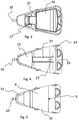
- This valve comprises a main body having a top float and a bottom float (as shown in Figure 1 ).
- the valve opens to allow water to enter the bottom of the growing container to a pre-determined and pre-set depth (usually 35mm).
- the valve then closes and will permit no further water to enter the container until all the original supply has been conveyed from the water chamber to the pot and consequently to the plant.
- the valve re-opens and another supply of water enters the growing container.
- the Autopot valve works on the basis of a vacuum being formed within the chambers to close the valve thereby to cut-off the water supply.
- WO 99/20100 discloses a liquid level control device which includes a casing nested between two floats. One float fits inside the casing and controls the water flow through an inlet via a closure.
- the present invention seeks to provide an improved valve assembly that, amongst other benefits, does not rely on the formation of a vacuum to shut off supply.
- a valve assembly for controlling the supply of water to a reservoir, the assembly comprising a main body having a floor and side walls, an upper float located within the main body and pivotally connected thereto, and a lower float located beneath the main body and pivotally connected thereto, the floor of the main body having an aperture; wherein the upper float is upwardly movable to a position to shut off the water supply to the reservoir; and wherein the lower float is movable upwardly to seal the aperture in the floor of the main body thereby to prevent water draining from the main body through said aperture or from prematurely filling.
- the main body comprises a inner section and a outer frame wherein the upper float is located within the inner section.
- the outer frame includes an inlet connected to the outlet of the water source.
- the upper float assembly comprises a main section and an elongate arm the distal end of which is connected to a transverse pivot bar.
- an end surface of the elongate arm includes a silicon plug which acts to seal the inlet when the elongate arm is pivotally raised relative to the main body.
- the lower float comprises an elongate arm one end of which is formed as a paddle section and the other of which extends to a transverse arm which includes a pivot bar.
- At least one side or end of the main body is adjustable in height.
- a valve assembly 1 constructed in accordance with the invention comprises a main body 2 having side walls 3 extending upwardly from the edges of a base or floor 4.
- the floor 4 of the main body has an aperture 5 through which water within the main body 2 can drain during use.
- a rear wall 6 of the main body 2 has a downwardly extending recess 7.
- An adjustable back plate 8 is attached to the rear wall 6 and extends across the recess 7 at a pre-determined height. The height that the back plate 8 extends up the recess 7 is adjustable. In use, the adjustability of the back plate 8 allows for a user to set a height, and thus a water level, at which water located outside the valve assembly 1 will flow over the rear wall 6 and into the main body 2.
- a front wall 9 of the main body 2 includes an inlet valve 10 which is connected, in use, to the outlet of a water source (not shown) to allow water to flow from the source into the valve assembly 1.
- the inlet valve 10 is sloped downwardly by approximately 5°.
- the main body 2 includes an outer frame 11 and an inner section 12.
- the inner section 12 holds water within the assembly 1 during use and includes the floor 5.
- the outer frame 11 is open to the ground includes at least one downwardly extending leg 13.
- the inlet valve 10 provides a path of flow of water from the source into the outer frame 11 and into a reservoir in which the valve assembly 1 stands in use.
- the reservoir will also house the plants and the like requiring irrigation.
- the main body 2 has further legs 14 extending downwardly from the other end of the main body 2 to provide stability and balance.
- an upper float assembly 15 Within the main body 2 is located an upper float assembly 15.
- the upper float 15 comprises a main section 16 and an elongate arm 17 which is connected at its distal end to a pivot bar 18 extending transverse to the elongate arm 17.
- the pivot bar 18 extends within and across the outer frame 11 of the main body 2 with the ends received within apertures 19 formed within outer frame section.
- the main section 16 is able to pivot within the main body 2 of valve assembly 1 thereby to float on the surface of water that is located within the main body 2 during use.
- the arm 17 includes a silicone plug 20 which acts to seal the inlet valve 10 when the upper float 15 is lifted (by raising of the water level) to a pre-determined height within the main body 2 thereby to shut off the valve 10 and prevent any further ingress of water from the source into the valve assembly 1.
- a lower float assembly 21 is pivotally connected to the underside of the main body 2.
- the lower float assembly 21 comprises an elongate arm 22 one end of which is formed as a paddle section 23 and the other of which extends to a transverse arm 24 which includes a pivot bar 25.
- the pivot bar 25 extends across the bottom of the main body 2 with the ends received within recesses 26 formed within the sides of bottom section of the body 2.
- the elongate arm 22 of the lower float 21 includes a silicon seal 27 facing upwardly therefrom. Pivotal movement of the float 21 in an upward direction causes the seal 27 to abut the underside of the aperture 5 within the main body thereby to seal the aperture 5 to prevent water from draining out of the main body 2.
- the valve assembly 1 is placed within a reservoir for example a tray or pot, which also holds the plants requiring irrigation.
- the height of the back plate 8 is set to a pre-determined height equating to the water level requirements for the reservoir.
- the inlet valve 10 is connected to the water source to provide a supply of water into the valve assembly 1. Initially the water flows into outer frame 11 of the assembly 1 and out of the bottom of the assembly 1 into the reservoir.
- the level of water in the reservoir gradually rises as water flows into it. This water is slowly absorbed by the plant through capillary action that naturally occurs in the growing medium.
- Raising of the reservoir water level gradually raises the lower float 21 which pivots about its pivot bar 25 relative to the main body.
- the float 21 will eventually reach a height wherein the silicon seal 27 abuts against the underside of the aperture 5 in the floor 4 of the main body 2 to close the aperture 5.
- water in the main body 2 is not able to drain out through the aperture 5.
- the reservoir water level continues to rise. Once the water level in the reservoir reaches the height of the back plate 8 the water flows over the back plate 8 into the main body 2 thereby filling the main body 2.
- the silicon plug 20 of the arm 17 of the float 15 eventually raises to a height wherein it seals the inlet valve 10 to prevent any further flow of water from the source into the valve assembly 1.
- the water supply remains shut off until the height of the water in the reservoir decreases to a level wherein the lower float 21 pivots downwardly to disengage the seal 27 with the aperture 5 at which point the water contained within the main body 2 is able to drain out through the aperture.
- the height of the water within the main body gradually decreases until a level where the upper float 15 pivots downwardly thereby releasing the silicon plug 20 from the inlet 10 to open the valve and introduce water from the source in the valve assembly 1 once again.
Landscapes
- Engineering & Computer Science (AREA)
- General Engineering & Computer Science (AREA)
- Mechanical Engineering (AREA)
- Water Supply & Treatment (AREA)
- Life Sciences & Earth Sciences (AREA)
- Environmental Sciences (AREA)
- Float Valves (AREA)
Claims (7)
- Ventilbaugruppe (1) zum Steuern der Wasserzufuhr zu einem Reservoir, wobei die Baugruppe einen Hauptkörper (2) umfasst, der einen Boden (4) und Seitenwände (3) aufweist, dadurch gekennzeichnet, dass die Baugruppe einen oberen Schwebekörper (15), der im Hauptkörper angeordnet ist und schwenkbar mit ihm verbunden ist, und einen unteren Schwebekörper (21) umfasst, der unterhalb des Hauptkörpers angeordnet ist und schwenkbar mit ihm verbunden ist, wobei der Boden des Hauptkörpers eine Öffnung (5) aufweist; wobei der obere Schwebekörper nach oben in eine Position bewegbar ist, um die Wasserzufuhr zu dem Reservoir zu unterbrechen; und wobei der untere Schwebekörper nach oben bewegbar ist, um die Öffnung in dem Boden des Hauptkörpers abzudichten, um zu verhindern, das Wasser von dem Hauptkörper durch die Öffnung ausläuft oder um es vor einem vorzeitigen Füllen zu bewahren.
- Ventil nach Anspruch 1, wobei der Hauptkörper einen inneren Abschnitt (12) und einen äußeren Rahmen (11) umfasst und wobei der obere Schwebekörper in dem inneren Abschnitt angeordnet ist.
- Ventil nach Anspruch 1 oder Anspruch 2, wobei der äußere Rahmen einen Zulauf (10) beinhaltet, der mit dem Ausgang der Wasserquelle verbunden ist.
- Ventil nach einem der Ansprüche 1 bis 3, wobei die obere Schwebekörperbaugruppe einen Hauptabschnitt (16) und einen länglichen Arm (17) umfasst, dessen distales Ende mit einer transversalen Rohrtraverse (18) verbunden ist.
- Ventil nach Anspruch 4, wobei eine Endfläche des länglichen Arms einen Silikonstöpsel (20) beinhaltet, der den Zulauf abdichtet, wenn der längliche Arm relativ zu dem Hauptkörper schwenkbar angehoben wird.
- Ventil nach einem der Ansprüche 1 bis 5, wobei der untere Schwebekörper einen länglichen Arm (22) umfasst, von dem ein Ende als ein Paddelabschnitt (23) ausgebildet ist und das andere Ende sich zu einem Transversalarm (24) erstreckt, der eine Rohrtraverse (25) beinhaltet.
- Ventil nach einem der vorherigen Ansprüche, wobei mindestens eine Seite oder ein Ende des Hauptkörpers in der Höhe verstellbar ist.
Applications Claiming Priority (2)
| Application Number | Priority Date | Filing Date | Title |
|---|---|---|---|
| GB201200855A GB2498542B (en) | 2012-01-19 | 2012-01-19 | Valve assembly |
| PCT/GB2013/000023 WO2013108007A1 (en) | 2012-01-19 | 2013-01-21 | Valve assembly |
Publications (2)
| Publication Number | Publication Date |
|---|---|
| EP2805090A1 EP2805090A1 (de) | 2014-11-26 |
| EP2805090B1 true EP2805090B1 (de) | 2018-09-05 |
Family
ID=45814207
Family Applications (1)
| Application Number | Title | Priority Date | Filing Date |
|---|---|---|---|
| EP13707422.5A Not-in-force EP2805090B1 (de) | 2012-01-19 | 2013-01-21 | Ventilanordnung |
Country Status (5)
| Country | Link |
|---|---|
| US (1) | US9453586B2 (de) |
| EP (1) | EP2805090B1 (de) |
| ES (1) | ES2700573T3 (de) |
| GB (1) | GB2498542B (de) |
| WO (1) | WO2013108007A1 (de) |
Families Citing this family (3)
| Publication number | Priority date | Publication date | Assignee | Title |
|---|---|---|---|---|
| GB2547069B (en) | 2016-11-17 | 2018-03-07 | Ralph Smith Jason | Liquid level control device |
| CN206958371U (zh) | 2017-05-18 | 2018-02-02 | 洪志平 | 水耕栽培系统的水位控制器 |
| GB2579340B (en) * | 2018-10-22 | 2021-04-07 | Hydrogarden Ltd | Irrigation valve |
Family Cites Families (8)
| Publication number | Priority date | Publication date | Assignee | Title |
|---|---|---|---|---|
| US4864771A (en) * | 1988-05-19 | 1989-09-12 | Fah Ah N | Automatic plant watering and feeding system |
| JP3433397B2 (ja) * | 1992-09-23 | 2003-08-04 | フィッシャー アンド ペイケル アプライアンシーズ リミテッド | フロート弁装置及び呼吸用加湿器 |
| AUPO989997A0 (en) * | 1997-10-20 | 1997-11-13 | Fah, Ah N. | A liquid level control device |
| US5964247A (en) * | 1997-11-19 | 1999-10-12 | American Standard Inc. | Fill valve |
| US6145532A (en) * | 1997-12-01 | 2000-11-14 | Walbro Corporation | Fuel tank fill level control and vapor venting valve |
| US6260574B1 (en) * | 2000-05-26 | 2001-07-17 | Lavelle Industries, Inc. | Toilet tank fill valve connectable to riser with pre-selected height |
| US6510866B2 (en) * | 2001-03-26 | 2003-01-28 | Wdi International, Inc. | Ball cock assembly, float assembly for same, and method of controlling liquid level in a tank |
| US7661438B2 (en) * | 2006-09-28 | 2010-02-16 | David Nichols-Roy | Water saver fill valve and assembly |
-
2012
- 2012-01-19 GB GB201200855A patent/GB2498542B/en not_active Expired - Fee Related
-
2013
- 2013-01-21 WO PCT/GB2013/000023 patent/WO2013108007A1/en not_active Ceased
- 2013-01-21 ES ES13707422T patent/ES2700573T3/es active Active
- 2013-01-21 US US14/373,339 patent/US9453586B2/en not_active Expired - Fee Related
- 2013-01-21 EP EP13707422.5A patent/EP2805090B1/de not_active Not-in-force
Also Published As
| Publication number | Publication date |
|---|---|
| EP2805090A1 (de) | 2014-11-26 |
| US9453586B2 (en) | 2016-09-27 |
| ES2700573T3 (es) | 2019-02-18 |
| GB201200855D0 (en) | 2012-02-29 |
| GB2498542B (en) | 2013-12-04 |
| WO2013108007A1 (en) | 2013-07-25 |
| GB2498542A (en) | 2013-07-24 |
| US20140352811A1 (en) | 2014-12-04 |
Similar Documents
| Publication | Publication Date | Title |
|---|---|---|
| US6886589B2 (en) | Float valve | |
| US4864771A (en) | Automatic plant watering and feeding system | |
| US9468166B2 (en) | Automatic subterranean watering system with refill indicator and gripping mechanism | |
| US20070022660A1 (en) | Irrigation unit | |
| CN206629556U (zh) | 一种自动浇水花盆 | |
| US9453586B2 (en) | Valve assembly | |
| US5671562A (en) | Liquid level control device | |
| JP5722488B1 (ja) | 排水装置及び栽培装置 | |
| US8533995B1 (en) | Automatic watering device for plants | |
| CN206851710U (zh) | 一种自动浇水装置 | |
| GB0601391D0 (en) | Sump Action Plant Waterer | |
| WO2014035294A1 (ru) | Способ автономного полива растений и гидропонное устройство для его осуществления | |
| CN106489688B (zh) | 一种自动浇花装置 | |
| KR20140043921A (ko) | 식물 재배용 친환경 양변기 물탱크 덮개 | |
| CN207383183U (zh) | 仿生学自动浇水器 | |
| RU2609388C1 (ru) | Осушительная система | |
| US20060150506A1 (en) | Water self-refilling plant pot | |
| US1851682A (en) | Poultry watering trough | |
| RU2609952C1 (ru) | Вакуумная дренажная система | |
| CN203968766U (zh) | 保湿花盆 | |
| US7117905B2 (en) | System and method for automatically filling a liquid receptacle | |
| CN209590650U (zh) | 一种微型水位控制器 | |
| RU2251255C1 (ru) | Устройство для автоматического орошения растений в горшках | |
| GB2579340A (en) | Irrigation valve | |
| RU128450U1 (ru) | Гидропонное устройство для автономного полива растений |
Legal Events
| Date | Code | Title | Description |
|---|---|---|---|
| PUAI | Public reference made under article 153(3) epc to a published international application that has entered the european phase |
Free format text: ORIGINAL CODE: 0009012 |
|
| 17P | Request for examination filed |
Effective date: 20140818 |
|
| AK | Designated contracting states |
Kind code of ref document: A1 Designated state(s): AL AT BE BG CH CY CZ DE DK EE ES FI FR GB GR HR HU IE IS IT LI LT LU LV MC MK MT NL NO PL PT RO RS SE SI SK SM TR |
|
| DAX | Request for extension of the european patent (deleted) | ||
| GRAP | Despatch of communication of intention to grant a patent |
Free format text: ORIGINAL CODE: EPIDOSNIGR1 |
|
| STAA | Information on the status of an ep patent application or granted ep patent |
Free format text: STATUS: GRANT OF PATENT IS INTENDED |
|
| INTG | Intention to grant announced |
Effective date: 20171030 |
|
| RBV | Designated contracting states (corrected) |
Designated state(s): AL AT BE BG CH CY CZ DE DK EE ES FI FR GR HR HU IE IS IT LI LT LU LV MC MK MT NL NO PL PT RO RS SE SI SK SM TR |
|
| GRAS | Grant fee paid |
Free format text: ORIGINAL CODE: EPIDOSNIGR3 |
|
| GRAA | (expected) grant |
Free format text: ORIGINAL CODE: 0009210 |
|
| STAA | Information on the status of an ep patent application or granted ep patent |
Free format text: STATUS: THE PATENT HAS BEEN GRANTED |
|
| AK | Designated contracting states |
Kind code of ref document: B1 Designated state(s): AL AT BE BG CH CY CZ DE DK EE ES FI FR GR HR HU IE IS IT LI LT LU LV MC MK MT NL NO PL PT RO RS SE SI SK SM TR |
|
| REG | Reference to a national code |
Ref country code: CH Ref legal event code: EP |
|
| REG | Reference to a national code |
Ref country code: AT Ref legal event code: REF Ref document number: 1038204 Country of ref document: AT Kind code of ref document: T Effective date: 20180915 |
|
| REG | Reference to a national code |
Ref country code: DE Ref legal event code: R096 Ref document number: 602013043076 Country of ref document: DE |
|
| REG | Reference to a national code |
Ref country code: IE Ref legal event code: FG4D |
|
| REG | Reference to a national code |
Ref country code: NL Ref legal event code: MP Effective date: 20180905 |
|
| REG | Reference to a national code |
Ref country code: LT Ref legal event code: MG4D |
|
| PG25 | Lapsed in a contracting state [announced via postgrant information from national office to epo] |
Ref country code: FI Free format text: LAPSE BECAUSE OF FAILURE TO SUBMIT A TRANSLATION OF THE DESCRIPTION OR TO PAY THE FEE WITHIN THE PRESCRIBED TIME-LIMIT Effective date: 20180905 Ref country code: LT Free format text: LAPSE BECAUSE OF FAILURE TO SUBMIT A TRANSLATION OF THE DESCRIPTION OR TO PAY THE FEE WITHIN THE PRESCRIBED TIME-LIMIT Effective date: 20180905 Ref country code: BG Free format text: LAPSE BECAUSE OF FAILURE TO SUBMIT A TRANSLATION OF THE DESCRIPTION OR TO PAY THE FEE WITHIN THE PRESCRIBED TIME-LIMIT Effective date: 20181205 Ref country code: NO Free format text: LAPSE BECAUSE OF FAILURE TO SUBMIT A TRANSLATION OF THE DESCRIPTION OR TO PAY THE FEE WITHIN THE PRESCRIBED TIME-LIMIT Effective date: 20181205 Ref country code: GR Free format text: LAPSE BECAUSE OF FAILURE TO SUBMIT A TRANSLATION OF THE DESCRIPTION OR TO PAY THE FEE WITHIN THE PRESCRIBED TIME-LIMIT Effective date: 20181206 Ref country code: RS Free format text: LAPSE BECAUSE OF FAILURE TO SUBMIT A TRANSLATION OF THE DESCRIPTION OR TO PAY THE FEE WITHIN THE PRESCRIBED TIME-LIMIT Effective date: 20180905 Ref country code: SE Free format text: LAPSE BECAUSE OF FAILURE TO SUBMIT A TRANSLATION OF THE DESCRIPTION OR TO PAY THE FEE WITHIN THE PRESCRIBED TIME-LIMIT Effective date: 20180905 |
|
| REG | Reference to a national code |
Ref country code: AT Ref legal event code: MK05 Ref document number: 1038204 Country of ref document: AT Kind code of ref document: T Effective date: 20180905 |
|
| REG | Reference to a national code |
Ref country code: ES Ref legal event code: FG2A Ref document number: 2700573 Country of ref document: ES Kind code of ref document: T3 Effective date: 20190218 |
|
| PG25 | Lapsed in a contracting state [announced via postgrant information from national office to epo] |
Ref country code: LV Free format text: LAPSE BECAUSE OF FAILURE TO SUBMIT A TRANSLATION OF THE DESCRIPTION OR TO PAY THE FEE WITHIN THE PRESCRIBED TIME-LIMIT Effective date: 20180905 Ref country code: AL Free format text: LAPSE BECAUSE OF FAILURE TO SUBMIT A TRANSLATION OF THE DESCRIPTION OR TO PAY THE FEE WITHIN THE PRESCRIBED TIME-LIMIT Effective date: 20180905 Ref country code: HR Free format text: LAPSE BECAUSE OF FAILURE TO SUBMIT A TRANSLATION OF THE DESCRIPTION OR TO PAY THE FEE WITHIN THE PRESCRIBED TIME-LIMIT Effective date: 20180905 |
|
| PG25 | Lapsed in a contracting state [announced via postgrant information from national office to epo] |
Ref country code: AT Free format text: LAPSE BECAUSE OF FAILURE TO SUBMIT A TRANSLATION OF THE DESCRIPTION OR TO PAY THE FEE WITHIN THE PRESCRIBED TIME-LIMIT Effective date: 20180905 Ref country code: IS Free format text: LAPSE BECAUSE OF FAILURE TO SUBMIT A TRANSLATION OF THE DESCRIPTION OR TO PAY THE FEE WITHIN THE PRESCRIBED TIME-LIMIT Effective date: 20190105 Ref country code: EE Free format text: LAPSE BECAUSE OF FAILURE TO SUBMIT A TRANSLATION OF THE DESCRIPTION OR TO PAY THE FEE WITHIN THE PRESCRIBED TIME-LIMIT Effective date: 20180905 Ref country code: PL Free format text: LAPSE BECAUSE OF FAILURE TO SUBMIT A TRANSLATION OF THE DESCRIPTION OR TO PAY THE FEE WITHIN THE PRESCRIBED TIME-LIMIT Effective date: 20180905 Ref country code: IT Free format text: LAPSE BECAUSE OF FAILURE TO SUBMIT A TRANSLATION OF THE DESCRIPTION OR TO PAY THE FEE WITHIN THE PRESCRIBED TIME-LIMIT Effective date: 20180905 Ref country code: NL Free format text: LAPSE BECAUSE OF FAILURE TO SUBMIT A TRANSLATION OF THE DESCRIPTION OR TO PAY THE FEE WITHIN THE PRESCRIBED TIME-LIMIT Effective date: 20180905 Ref country code: RO Free format text: LAPSE BECAUSE OF FAILURE TO SUBMIT A TRANSLATION OF THE DESCRIPTION OR TO PAY THE FEE WITHIN THE PRESCRIBED TIME-LIMIT Effective date: 20180905 |
|
| PG25 | Lapsed in a contracting state [announced via postgrant information from national office to epo] |
Ref country code: SM Free format text: LAPSE BECAUSE OF FAILURE TO SUBMIT A TRANSLATION OF THE DESCRIPTION OR TO PAY THE FEE WITHIN THE PRESCRIBED TIME-LIMIT Effective date: 20180905 Ref country code: PT Free format text: LAPSE BECAUSE OF FAILURE TO SUBMIT A TRANSLATION OF THE DESCRIPTION OR TO PAY THE FEE WITHIN THE PRESCRIBED TIME-LIMIT Effective date: 20190105 Ref country code: SK Free format text: LAPSE BECAUSE OF FAILURE TO SUBMIT A TRANSLATION OF THE DESCRIPTION OR TO PAY THE FEE WITHIN THE PRESCRIBED TIME-LIMIT Effective date: 20180905 |
|
| REG | Reference to a national code |
Ref country code: DE Ref legal event code: R097 Ref document number: 602013043076 Country of ref document: DE |
|
| PLBE | No opposition filed within time limit |
Free format text: ORIGINAL CODE: 0009261 |
|
| STAA | Information on the status of an ep patent application or granted ep patent |
Free format text: STATUS: NO OPPOSITION FILED WITHIN TIME LIMIT |
|
| PG25 | Lapsed in a contracting state [announced via postgrant information from national office to epo] |
Ref country code: DK Free format text: LAPSE BECAUSE OF FAILURE TO SUBMIT A TRANSLATION OF THE DESCRIPTION OR TO PAY THE FEE WITHIN THE PRESCRIBED TIME-LIMIT Effective date: 20180905 |
|
| 26N | No opposition filed |
Effective date: 20190606 |
|
| PG25 | Lapsed in a contracting state [announced via postgrant information from national office to epo] |
Ref country code: MC Free format text: LAPSE BECAUSE OF FAILURE TO SUBMIT A TRANSLATION OF THE DESCRIPTION OR TO PAY THE FEE WITHIN THE PRESCRIBED TIME-LIMIT Effective date: 20180905 Ref country code: SI Free format text: LAPSE BECAUSE OF FAILURE TO SUBMIT A TRANSLATION OF THE DESCRIPTION OR TO PAY THE FEE WITHIN THE PRESCRIBED TIME-LIMIT Effective date: 20180905 |
|
| REG | Reference to a national code |
Ref country code: CH Ref legal event code: PL |
|
| PG25 | Lapsed in a contracting state [announced via postgrant information from national office to epo] |
Ref country code: LU Free format text: LAPSE BECAUSE OF NON-PAYMENT OF DUE FEES Effective date: 20190121 |
|
| REG | Reference to a national code |
Ref country code: BE Ref legal event code: MM Effective date: 20190131 |
|
| REG | Reference to a national code |
Ref country code: IE Ref legal event code: MM4A |
|
| PG25 | Lapsed in a contracting state [announced via postgrant information from national office to epo] |
Ref country code: BE Free format text: LAPSE BECAUSE OF NON-PAYMENT OF DUE FEES Effective date: 20190131 |
|
| PG25 | Lapsed in a contracting state [announced via postgrant information from national office to epo] |
Ref country code: LI Free format text: LAPSE BECAUSE OF NON-PAYMENT OF DUE FEES Effective date: 20190131 Ref country code: CH Free format text: LAPSE BECAUSE OF NON-PAYMENT OF DUE FEES Effective date: 20190131 |
|
| PG25 | Lapsed in a contracting state [announced via postgrant information from national office to epo] |
Ref country code: IE Free format text: LAPSE BECAUSE OF NON-PAYMENT OF DUE FEES Effective date: 20190121 |
|
| PG25 | Lapsed in a contracting state [announced via postgrant information from national office to epo] |
Ref country code: TR Free format text: LAPSE BECAUSE OF FAILURE TO SUBMIT A TRANSLATION OF THE DESCRIPTION OR TO PAY THE FEE WITHIN THE PRESCRIBED TIME-LIMIT Effective date: 20180905 |
|
| PG25 | Lapsed in a contracting state [announced via postgrant information from national office to epo] |
Ref country code: MT Free format text: LAPSE BECAUSE OF NON-PAYMENT OF DUE FEES Effective date: 20190121 |
|
| PG25 | Lapsed in a contracting state [announced via postgrant information from national office to epo] |
Ref country code: CY Free format text: LAPSE BECAUSE OF FAILURE TO SUBMIT A TRANSLATION OF THE DESCRIPTION OR TO PAY THE FEE WITHIN THE PRESCRIBED TIME-LIMIT Effective date: 20180905 |
|
| PG25 | Lapsed in a contracting state [announced via postgrant information from national office to epo] |
Ref country code: HU Free format text: LAPSE BECAUSE OF FAILURE TO SUBMIT A TRANSLATION OF THE DESCRIPTION OR TO PAY THE FEE WITHIN THE PRESCRIBED TIME-LIMIT; INVALID AB INITIO Effective date: 20130121 |
|
| PGFP | Annual fee paid to national office [announced via postgrant information from national office to epo] |
Ref country code: DE Payment date: 20220119 Year of fee payment: 10 |
|
| PGFP | Annual fee paid to national office [announced via postgrant information from national office to epo] |
Ref country code: FR Payment date: 20220119 Year of fee payment: 10 Ref country code: ES Payment date: 20220325 Year of fee payment: 10 Ref country code: CZ Payment date: 20220121 Year of fee payment: 10 |
|
| PG25 | Lapsed in a contracting state [announced via postgrant information from national office to epo] |
Ref country code: MK Free format text: LAPSE BECAUSE OF FAILURE TO SUBMIT A TRANSLATION OF THE DESCRIPTION OR TO PAY THE FEE WITHIN THE PRESCRIBED TIME-LIMIT Effective date: 20180905 |
|
| REG | Reference to a national code |
Ref country code: DE Ref legal event code: R119 Ref document number: 602013043076 Country of ref document: DE |
|
| PG25 | Lapsed in a contracting state [announced via postgrant information from national office to epo] |
Ref country code: DE Free format text: LAPSE BECAUSE OF NON-PAYMENT OF DUE FEES Effective date: 20230801 Ref country code: CZ Free format text: LAPSE BECAUSE OF NON-PAYMENT OF DUE FEES Effective date: 20230121 |
|
| PG25 | Lapsed in a contracting state [announced via postgrant information from national office to epo] |
Ref country code: FR Free format text: LAPSE BECAUSE OF NON-PAYMENT OF DUE FEES Effective date: 20230131 |
|
| REG | Reference to a national code |
Ref country code: ES Ref legal event code: FD2A Effective date: 20240402 |
|
| PG25 | Lapsed in a contracting state [announced via postgrant information from national office to epo] |
Ref country code: ES Free format text: LAPSE BECAUSE OF NON-PAYMENT OF DUE FEES Effective date: 20230122 |
|
| PG25 | Lapsed in a contracting state [announced via postgrant information from national office to epo] |
Ref country code: ES Free format text: LAPSE BECAUSE OF NON-PAYMENT OF DUE FEES Effective date: 20230122 |