US1851682A - Poultry watering trough - Google Patents
Poultry watering trough Download PDFInfo
- Publication number
- US1851682A US1851682A US308952A US30895228A US1851682A US 1851682 A US1851682 A US 1851682A US 308952 A US308952 A US 308952A US 30895228 A US30895228 A US 30895228A US 1851682 A US1851682 A US 1851682A
- Authority
- US
- United States
- Prior art keywords
- reservoir
- pan
- valve
- arm
- pipe
- Prior art date
- Legal status (The legal status is an assumption and is not a legal conclusion. Google has not performed a legal analysis and makes no representation as to the accuracy of the status listed.)
- Expired - Lifetime
Links
- 244000144977 poultry Species 0.000 title description 5
- 239000012530 fluid Substances 0.000 description 5
- 239000007788 liquid Substances 0.000 description 3
- 238000010276 construction Methods 0.000 description 2
- 210000003141 lower extremity Anatomy 0.000 description 2
- 241001465754 Metazoa Species 0.000 description 1
- 210000002445 nipple Anatomy 0.000 description 1
- XLYOFNOQVPJJNP-UHFFFAOYSA-N water Substances O XLYOFNOQVPJJNP-UHFFFAOYSA-N 0.000 description 1
Images
Classifications
-
- A—HUMAN NECESSITIES
- A01—AGRICULTURE; FORESTRY; ANIMAL HUSBANDRY; HUNTING; TRAPPING; FISHING
- A01K—ANIMAL HUSBANDRY; AVICULTURE; APICULTURE; PISCICULTURE; FISHING; REARING OR BREEDING ANIMALS, NOT OTHERWISE PROVIDED FOR; NEW BREEDS OF ANIMALS
- A01K39/00—Feeding or drinking appliances for poultry or other birds
- A01K39/02—Drinking appliances
- A01K39/024—Drinking appliances with float-controlled supply
Definitions
- My said invention relates to improvements in poultry watering troughs and it is an object of the invention to provide a device of this characterhavinga shallow trough with a reservoir or tank for reserve liquid with improved means for controlling the supply of the liquid from the reservoir to the trough.
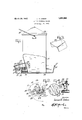
- Figure 1 is a side elevation partly insection illustrating one application of my invention
- FIG. 2 a detail fragmentary perspective, illustrating a modified form of my invention
- FIG. 4 an enlarged fragmentary detail.
- reference character 10 indicates a shallow pan or container preferably circular in shape and having its upper edge rolled over at 11 providinga're-enforcing rim.
- the pan 10 may be provided with a central upset portion 12 about which the lower extremity of a sleeve 13 arranged to form a fluid reservoir or tank adapted to contain a quantityof fluidto be dispensed to poultry, animals or the like is adapted to be soldered, or secured in any other desired manner, in upright position.
- the reservoir may be of any desired shape or construction, but preferably conforms in general outline to the circular pan 10 to which it is afiixed. It is also bent inwardly adjacent its lower end to providespace for valvemechanism between the reservoir and the side of the pan adapted to control the supply of fluid from the reservoir into said pan.
- a short nipple or pipe 14 is soldered or otherwise secured inan opening through the wall of the inwardly bent portion of the reservoir adjacent the bottom of the same and the end of the, pipe 14 is closed at 15.
- a small opening or discharge outlet 16 is provided through the upper'por- A tion of the pipe and a needle valve is mounted in a position to close the opening 16, said needle valve being provided with a pair of fixed spaced abutments 18 and 19.
- a substanially U-shaped bracket 20 is secured in an upright'position in any desired manner on the pipe 14 adjacent its end and forms a support for a pivot pin 21 secured to the central portion of an arm 22, said arm carrying a float23 at its outer end, and having an opening 2 1 at its inner end, in which is disposed the'stem of the needle valve 17, said arm being disposed between the abutments 18 and 19 so that the m'o'vement of the arm relative to thejvalve 17 is limited and the arm is caused to remain substantially-at right angles to the stem of the valve.
- valve is maintained at'all times substantially at rlght angles to the arm 22 which prevents the lowering of the arm and the float-carried thereby a sufiicient distance ;to cause dis.
- reservoir 13 is provided which is similar in construction to the reservoir, of the preferred form previously de-.
- Saidreservoir is mounted ina shallow pan 10 having its upperedge rolled over ingits body centrally upset as in thep'referred form of my invention."
- the reservoir may also be bentinwardly adjacent its lower end, to provide 'suflic'ient space for valve mechanism between the reservoir and the side of the pan adapted tocontrol the supply of at 11 providing a re-enforcing rim and havby means of a stop 26.
- the pipe is provided with a small opening 27 through its upper side through which the fluid in the container may flow to fill the space or trough formed about the reservoir in the pan.
- I provide a bracket 28 on the pipe 25 and on said bracket I pivotally mount a lever 29 having a float 30 at its outer end and a needle valve 31 at its inner end, said needle valve being disposed in a, positionto, close theopening 27 when the float isbuoyed up by means of the water or other fluid in the trough.
- the stop 26 forms a rest for and limits the lowering movement of the float when the fluid in the trough is exhausted beyond a predetermined level.
- the needle valve is .therefore const'antly maintained. in position so that itwill properlyseat and shut offth'e supply.
- a handle 35 is preferably secured to the reservoir to facilitate carryingth'e same, and a rergovable top or cover 36 may also be .
- pro- W e My invention comprises few and simple parts, there being a pan, a sleeve or pipe secured therein and a valve for controlling thefflow of liquid from the reservoirthrough saidsleeve into'said pan.
- the guard andpwp are desirable for insuring the operation of the valve and for keeping foreign matter but of the reservoir.
- a device of the class described comprising'ashallow pan, an upright sleeve mounted in said pan, a pipe extending through the lower extremity of said sleeve into the pan and having an opening adjacent its end and with its'outer end closed, ,a' bracket on said the needle valve to prevent it from becoming disengaged from the opening which it closes substantially as set forth.
- a device of the class described comprising a shallow receptacle, a reservoir mounted in said receptacle a supply pipe projecting from saidireservoir into the receptacle and having dischargeopen ing therein, a bracket fastened to the supply pipe, an arm pivoted to the. said bracket,i'a.: float fixed to.
- the-outerenrl .Df tl1e,arm, a.va1ve carriedbyithe inner end of the arm and having a portion disposed in the discharge opening of the pipe, a stop on pipe, an arm pivoted to said bracketadjacent its central portion, afloat on one end of the arm, a needle 'valve on the opposite end of thearm, and a stop on the closed end ofthe Pi e r limiting t e inw d meme? 9f
Landscapes
- Life Sciences & Earth Sciences (AREA)
- Environmental Sciences (AREA)
- Birds (AREA)
- Animal Husbandry (AREA)
- Biodiversity & Conservation Biology (AREA)
- Catching Or Destruction (AREA)
Description
March 29, 1932. R. oAKEs POULTRY WATERING THOUGH Filed Sept. 28, 1928 LucianR. 0a lvs Fatented Mar. 29,1932
g UNITED'STATEVSL 'LUoI'AN R. CAKES, or. TIPTON, INDIANA,-ASSIGNOR To THE oAKEsMANUrAc'rURING COMPANY, or 'rIrrroN, INDIANA, A CORPORATION 01" INDIANA POULTRY'WATERING rnouen Application filed September 28, 1928. Serial No. 308,952."
My said invention relates to improvements in poultry watering troughs and it is an object of the invention to provide a device of this characterhavinga shallow trough with a reservoir or tank for reserve liquid with improved means for controlling the supply of the liquid from the reservoir to the trough.
Referring to the accompanying drawings, which are made a part hereof and on which similar reference characters indicate similar parts,
Figure 1 is a side elevation partly insection illustrating one application of my invention,
Figure 2, a detail fragmentary perspective, illustrating a modified form of my invention,
Figure 3, aperspective of a cover for parts of the device, and
Figure 4:, an enlarged fragmentary detail.
In the drawings reference character 10indicates a shallow pan or container preferably circular in shape and having its upper edge rolled over at 11 providinga're-enforcing rim. The pan 10 may be provided with a central upset portion 12 about which the lower extremity of a sleeve 13 arranged to form a fluid reservoir or tank adapted to contain a quantityof fluidto be dispensed to poultry, animals or the like is adapted to be soldered, or secured in any other desired manner, in upright position. The reservoir may be of any desired shape or construction, but preferably conforms in general outline to the circular pan 10 to which it is afiixed. It is also bent inwardly adjacent its lower end to providespace for valvemechanism between the reservoir and the side of the pan adapted to control the supply of fluid from the reservoir into said pan.
In the preferred form of the invention, shown in Figure 1, a short nipple or pipe 14 is soldered or otherwise secured inan opening through the wall of the inwardly bent portion of the reservoir adjacent the bottom of the same and the end of the, pipe 14 is closed at 15. A small opening or discharge outlet 16 is provided through the upper'por- A tion of the pipe and a needle valve is mounted in a position to close the opening 16, said needle valve being provided with a pair of fixed spaced abutments 18 and 19. A substanially U-shaped bracket 20 is secured in an upright'position in any desired manner on the pipe 14 adjacent its end and forms a support for a pivot pin 21 secured to the central portion of an arm 22, said arm carrying a float23 at its outer end, and having an opening 2 1 at its inner end, in which is disposed the'stem of the needle valve 17, said arm being disposed between the abutments 18 and 19 so that the m'o'vement of the arm relative to thejvalve 17 is limited and the arm is caused to remain substantially-at right angles to the stem of the valve. l
P On account of the specific arrangement of the parts as just described, when the .float lowers it elevates the needle valve toa position so that, the major portionyjof the discharge outlet-16 is unobstructed but the point ofthe needle valveis in aposition'to be guidedinto seating position when it, is lowered. Likewiseon account of the stem of the valve and the opening 24in the arm 22 beingnearly the same size and the abut.
engagement of the valve from the opening which itcloses. I In the modified formof the invention, as shown in Figure 2a reservoir 13 is provided which is similar in construction to the reservoir, of the preferred form previously de-.
scribed; Saidreservoir, is mounted ina shallow pan 10 having its upperedge rolled over ingits body centrally upset as in thep'referred form of my invention." The reservoir may also be bentinwardly adjacent its lower end, to provide 'suflic'ient space for valve mechanism between the reservoir and the side of the pan adapted tocontrol the supply of at 11 providing a re-enforcing rim and havby means of a stop 26. The pipe is provided with a small opening 27 through its upper side through which the fluid in the container may flow to fill the space or trough formed about the reservoir in the pan. I provide a bracket 28 on the pipe 25 and on said bracket I pivotally mount a lever 29 having a float 30 at its outer end and a needle valve 31 at its inner end, said needle valve being disposed in a, positionto, close theopening 27 when the float isbuoyed up by means of the water or other fluid in the trough. The stop 26 forms a rest for and limits the lowering movement of the float when the fluid in the trough is exhausted beyond a predetermined level. The needle valve is .therefore const'antly maintained. in position so that itwill properlyseat and shut offth'e supply.
In order to protect the valve structures shown in Figures land 2 and, associated parts sothat they will'a't all times function properly I ha ve securedfa pair of strips32 tothe reservoir 13, one on each side of the valve in ugrigh't position and" a "pair of grooved mere e'rs 33 are secured in upright position to the lsideof the pan 10. 'A substantially U-shape'd casing 34 comprising a body 'ortiQIiand a pair of legs is adapted tobe eld bysaid uprights in position over said valve withthe front edges of the legs disposed (in the grooves in the "uprights secured on the side'of the 'pan."
A handle 35 is preferably secured to the reservoir to facilitate carryingth'e same, and a rergovable top or cover 36 may also be .pro- W e "My invention comprises few and simple parts, there being a pan, a sleeve or pipe secured therein and a valve for controlling thefflow of liquid from the reservoirthrough saidsleeve into'said pan. The guard andpwp are desirable for insuring the operation of the valve and for keeping foreign matter but of the reservoir. i 'Itwill'be' obvious to those skilled in the art that various changes may be made in my device without departing from the spirit r the invention, and I, therefore, do not limit m'y self to what is shownin the drawings and described in the specification, but only asset forth in the appended claims. 3 Having thus fully described my said invention, what I claim as new and desire to secure by Letters Patent, is:
1. A device of the class described comprising'ashallow pan, an upright sleeve mounted in said pan, a pipe extending through the lower extremity of said sleeve into the pan and having an opening adjacent its end and with its'outer end closed, ,a' bracket on said the needle valve to prevent it from becoming disengaged from the opening which it closes substantially as set forth.
2. A device of the class described comprising a shallow receptacle, a reservoir mounted in said receptacle a supply pipe projecting from saidireservoir into the receptacle and having dischargeopen ing therein, a bracket fastened to the supply pipe, an arm pivoted to the. said bracket,i'a.: float fixed to. the-outerenrl .Df tl1e,arm, a.va1ve carriedbyithe inner end of the arm and having a portion disposed in the discharge opening of the pipe, a stop on pipe, an arm pivoted to said bracketadjacent its central portion, afloat on one end of the arm, a needle 'valve on the opposite end of thearm, and a stop on the closed end ofthe Pi e r limiting t e inw d meme? 9f
Priority Applications (1)
| Application Number | Priority Date | Filing Date | Title |
|---|---|---|---|
| US308952A US1851682A (en) | 1928-09-28 | 1928-09-28 | Poultry watering trough |
Applications Claiming Priority (1)
| Application Number | Priority Date | Filing Date | Title |
|---|---|---|---|
| US308952A US1851682A (en) | 1928-09-28 | 1928-09-28 | Poultry watering trough |
Publications (1)
| Publication Number | Publication Date |
|---|---|
| US1851682A true US1851682A (en) | 1932-03-29 |
Family
ID=23196044
Family Applications (1)
| Application Number | Title | Priority Date | Filing Date |
|---|---|---|---|
| US308952A Expired - Lifetime US1851682A (en) | 1928-09-28 | 1928-09-28 | Poultry watering trough |
Country Status (1)
| Country | Link |
|---|---|
| US (1) | US1851682A (en) |
Cited By (5)
| Publication number | Priority date | Publication date | Assignee | Title |
|---|---|---|---|---|
| US2477138A (en) * | 1945-03-02 | 1949-07-26 | James Mfg Co | Pressure poultry waterer |
| US3138140A (en) * | 1962-01-24 | 1964-06-23 | Eldred B Medlock | Automatic poultry waterer |
| USD693067S1 (en) * | 2012-12-21 | 2013-11-05 | Miller Manufacturing Company | Watering device |
| US20160255808A1 (en) * | 2015-03-03 | 2016-09-08 | Tractor Supply Company | Animal Watering Apparatus |
| US20220225595A1 (en) * | 2021-01-19 | 2022-07-21 | Maximilian B. Lee | Poultry Drinker System |
-
1928
- 1928-09-28 US US308952A patent/US1851682A/en not_active Expired - Lifetime
Cited By (7)
| Publication number | Priority date | Publication date | Assignee | Title |
|---|---|---|---|---|
| US2477138A (en) * | 1945-03-02 | 1949-07-26 | James Mfg Co | Pressure poultry waterer |
| US3138140A (en) * | 1962-01-24 | 1964-06-23 | Eldred B Medlock | Automatic poultry waterer |
| USD693067S1 (en) * | 2012-12-21 | 2013-11-05 | Miller Manufacturing Company | Watering device |
| US20160255808A1 (en) * | 2015-03-03 | 2016-09-08 | Tractor Supply Company | Animal Watering Apparatus |
| US9743642B2 (en) * | 2015-03-03 | 2017-08-29 | Tractor Supply Company | Animal watering apparatus |
| US20220225595A1 (en) * | 2021-01-19 | 2022-07-21 | Maximilian B. Lee | Poultry Drinker System |
| US11564378B2 (en) * | 2021-01-19 | 2023-01-31 | Maximilian B. Lee | Poultry drinker system |
Similar Documents
| Publication | Publication Date | Title |
|---|---|---|
| US4223837A (en) | Dosed delivery device for liquids, particularly for delivering water to vegetal cultivations | |
| US2845046A (en) | Water supplying device for poultry | |
| US1851682A (en) | Poultry watering trough | |
| JP2012130614A (en) | Rice cooker | |
| US1811375A (en) | Poultry drinking fountain | |
| US1928103A (en) | Float controlled drinking fountain | |
| US3483847A (en) | Poultry water cup and valve | |
| US3027872A (en) | Stock waterer | |
| US2590266A (en) | Hog waterer | |
| US1783891A (en) | Feed tank | |
| US2162314A (en) | Poultry fountain | |
| US2452305A (en) | Drinking fountain | |
| US1716239A (en) | Poultry watering trough | |
| US1881838A (en) | Hog watering device | |
| US2669220A (en) | Guard for poultry drinking fountain bowls | |
| US2501727A (en) | Drinking fount for poultry | |
| US2150499A (en) | Automatic water fountain for chickens | |
| US1961092A (en) | Automatic waterer | |
| US1521804A (en) | Hog waterer | |
| US2387664A (en) | Fount for poultry and other domestic animals | |
| US2142556A (en) | Siphon-fed drinking trough | |
| US1725628A (en) | Stock-watering tank | |
| US2739609A (en) | Automatic liquid feed valve | |
| US1446701A (en) | Automatic poultry waterer | |
| US3079892A (en) | Poultry watering fountain |