EP2804465B1 - Bale handling apparatus - Google Patents
Bale handling apparatus Download PDFInfo
- Publication number
- EP2804465B1 EP2804465B1 EP13706663.5A EP13706663A EP2804465B1 EP 2804465 B1 EP2804465 B1 EP 2804465B1 EP 13706663 A EP13706663 A EP 13706663A EP 2804465 B1 EP2804465 B1 EP 2804465B1
- Authority
- EP
- European Patent Office
- Prior art keywords
- bale
- frame
- conveyor belt
- spreader head
- rollers
- Prior art date
- Legal status (The legal status is an assumption and is not a legal conclusion. Google has not performed a legal analysis and makes no representation as to the accuracy of the status listed.)
- Active
Links
- 239000000463 material Substances 0.000 claims description 8
- 230000037431 insertion Effects 0.000 claims 2
- 238000003780 insertion Methods 0.000 claims 2
- 239000010902 straw Substances 0.000 description 7
- 230000004048 modification Effects 0.000 description 4
- 238000012986 modification Methods 0.000 description 4
- 239000002184 metal Substances 0.000 description 3
- 230000007480 spreading Effects 0.000 description 3
- 238000005728 strengthening Methods 0.000 description 2
- 229910000760 Hardened steel Inorganic materials 0.000 description 1
- 229910000831 Steel Inorganic materials 0.000 description 1
- 238000011109 contamination Methods 0.000 description 1
- 230000008878 coupling Effects 0.000 description 1
- 238000010168 coupling process Methods 0.000 description 1
- 238000005859 coupling reaction Methods 0.000 description 1
- 238000006073 displacement reaction Methods 0.000 description 1
- 230000007246 mechanism Effects 0.000 description 1
- 230000009467 reduction Effects 0.000 description 1
- 229910001220 stainless steel Inorganic materials 0.000 description 1
- 239000010935 stainless steel Substances 0.000 description 1
- 239000010959 steel Substances 0.000 description 1
- 235000012431 wafers Nutrition 0.000 description 1
Images


Classifications
-
- A—HUMAN NECESSITIES
- A01—AGRICULTURE; FORESTRY; ANIMAL HUSBANDRY; HUNTING; TRAPPING; FISHING
- A01F—PROCESSING OF HARVESTED PRODUCE; HAY OR STRAW PRESSES; DEVICES FOR STORING AGRICULTURAL OR HORTICULTURAL PRODUCE
- A01F29/00—Cutting apparatus specially adapted for cutting hay, straw or the like
- A01F29/005—Cutting apparatus specially adapted for cutting hay, straw or the like for disintegrating and cutting up bales of hay, straw or fodder
-
- A—HUMAN NECESSITIES
- A01—AGRICULTURE; FORESTRY; ANIMAL HUSBANDRY; HUNTING; TRAPPING; FISHING
- A01K—ANIMAL HUSBANDRY; AVICULTURE; APICULTURE; PISCICULTURE; FISHING; REARING OR BREEDING ANIMALS, NOT OTHERWISE PROVIDED FOR; NEW BREEDS OF ANIMALS
- A01K5/00—Feeding devices for stock or game ; Feeding wagons; Feeding stacks
- A01K5/001—Fodder distributors with mixer or shredder
- A01K5/005—Fodder distributors with mixer or shredder where fodder, e.g. bales, is conveyed by conveyor or slide to mixing or shredding elements on transversal and horizontal axes
Definitions
- the present invention relates to an agricultural apparatus used to distribute elements of a bale (such as a straw bale, for example) typically, though not exclusively, for the purpose of spreading the straw on the ground.
- a bale such as a straw bale, for example
- bale-spreading apparatus that may be mounted to a tractor or other agricultural vehicle via an extended, hydraulically-operated arm, known as a loader.
- FR2765773 discloses an agricultural machine for shredding straw, comprising a crate and a conveyor belt formed from two endless chains to drive the straw towards a shredder.
- the present invention provides a bale handling apparatus having: a box frame which retains a bale of material; a conveyor surface provided by a continuous conveyor belt, mounted on the box frame and upon which the bale rests, the conveyor belt being operable to move the bale in a longitudinal direction towards a spreader head that ejects bale material from the apparatus; the conveyor belt extending around at least two rollers spaced apart in the longitudinal direction; characterised in that: (a) the apparatus further comprises a rectangular frame located on the side of the apparatus by means of which the apparatus may be connected to a loader and a pair of horizontal support struts forming part of the box frame and extending in a lateral direction at the base of the box frame, the support struts providing additional strength for the apparatus to be carried transversely by the loader, and the support struts extending parallel to the rollers and inside the continuum of the conveyor belt; and (b) a sequence of guide rollers are provided within the continuum of the conveyor belt.
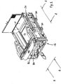
- a bale-handling apparatus which, in the present embodiment is an apparatus for spreading bale material, has a generally rectangular, box-like shape.
- a bale of material such as straw is inserted into the box area 12, whereupon a conveyor belt 14 upon which the bale sits urges the bale against a bale spreader head 16.
- Rotors of the spreader head 16 transform the bale into pieces at the same time as throwing these pieces out of the apparatus in the direction of arrow E in Fig. 1 , thereby to provide a straw carpet which can be useful for animal bedding, or absorbing moisture on muddy ground, for example.
- the apparatus is carried upon the extended loading arm of a tractor, for example, known as a loader. Connection of the apparatus to the loader is by means of a rectangular frame 20 located on the side of the apparatus, while power for the various motors operating the conveyor belt 14 and rotors 16 is provided hydraulically, via the loader arm, from the tractor.
- the apparatus is given structural integrity by a combination of formed sheet metal webs and steel struts.
- the basic structural chassis or frame of the apparatus comprises, in the present embodiment, two pairs (one pair on each longitudinal side) of, parallel horizontal struts 24 extending along the longitudinal (i.e. the longest) sides of the rectangular box.
- the struts of the two longitudinal pairs are each interconnected at one end (the right hand end in Fig. 2 ) to two parallel, horizontally-extending lateral struts 26.
- the other ends of the longitudinal struts 24 is the end of the apparatus adjacent the spreader head 16 and two further such lateral struts interconnect the other ends of the longitudinal struts 24 though these are not shown in the drawings.
- the longitudinal and lateral struts 24, 26 define a basic box chassis.
- This box chassis is given additional structural strength, particularly against torsional loads, by means of sheet metal webs extending at various points between the pairs of struts 24 and 26.
- Two additional, horizontal strengthening support struts 30 extend in the lateral direction at the base of the box. These provide additional strength which is required for the apparatus to be carried by the loader transversely (that is to say in such a way that the spreader head operates to eject straw to the side of the loader rather than to the front).
- the support struts 30 may be replaced with struts whose purpose is to provide structural stability, whereby the frame 20 may then be mounted by means of straps (for example of stainless steel) resulting in a lower overall weight.
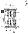
- a conveyor belt 14 is located at the base of the box so that it effectively extends around the horizontal support struts 30.
- This configuration enables strengthening of the base of the apparatus at the same time as avoiding an increase to any significant degree in the height (and therefore weight) of the box.
- the conveyor belt illustrated in section in Fig. 3 , extends around a principal drive roller 32 located at one end of the box, and then over a sequence of guide rollers 34 which are journalled for rotation relative to the lower longitudinal struts 24. These additional support rollers ensure that no bales become 'stranded' as a result of insufficient contact with the conveyor belt; a difficulty which may more likely otherwise occur with round bales.
- brushes may be mounted to the apparatus to prevent extraneous material from falling into the space adjacent the rollers and potentially causing an obstruction to the motion of the belt 14.
- the end of the conveyor belt adjacent the spreader head 16 is effectively chamfered by location of the final guide roller 34F below the height of the others. This facilitates easy loading of a bale into the box simply by movement of the tractor to 'scoop' a bale up from a stack of bales, known as 'self loading'.
- the slope provided by the chamfering reduces the likelihood of quadrant bale wafers falling backwards away from the spreader head 16, which would otherwise slow down spreading of rectangular bales.
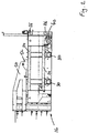
- the principal drive roller 32 for the belt 14 is adjustable laterally to enable adjustment of the tension in the conveyor belt 14; notably, the drive roller 32 has a larger diameter than all of the other rollers, this providing a larger contact area with the belt and providing more reliable, efficient drive thereof.
- the roller 32 is driven by means of a hydraulically-powered motor and reduction gearbox 40. This is shown in detail in Fig. 7 and in cutaway form in Fig. 8 .
- the motor worm 42 meshes with a gear 44 of the gearbox whose drive shaft then drives the principal roller 32; the arrangement being encased to avoid jamming of the gears due to contamination.
- the bevel gear shaft 44 also provides the journal bearing for the drive roller 32. This permits the use of a smaller hydraulic displacement motor which operates at a higher and more efficient speed.
- the spreader head 16 is mounted upon a pair of forked lifting arms 50, each pivotally mounted upon an upper longitudinal strut 24 via a bracket 52.
- the forked ends of the lifting arms carry the frame 60 of the spreader head 16; the frame 60 comprising pairs of vertical and lateral frame struts 62, 64 respectively.
- the lifting arms 50 are preferably made of folded sheet metal, which enables good structural strength whilst simultaneously reducing weight.
- the spreader rotors 70 are carried upon rotor shafts 72, each journalled at its ends in the lateral frame struts for rotation relative to the spreader head frame 60.
- Elevation of the lifting arms 50 (this is done by a hydraulic actuating mechanism - not shown - and powered from the tractor hydraulic system) therefore results in a corresponding elevation of the entire spreader head 16 (that is to say the frame and the rotor shafts 72). This elevation takes place to enable loading of a new bale into the box defined by the chassis (and described above).
- the lifting arms are mounted upon the upper part of the longitudinal struts 24. This enables closer coupling of the apparatus to the loader by means of the frame 20, since no clearance has to be accounted for. Alternative embodiments with side mounting of the lifting arms is possible.
- the rotors 70 are concentrically mounted upon the rotor shafts 72 (see Figs 1 , 3 and 4 , for example) and comprise planar, elliptical blade holders 80, preferably manufactured from hardened steel, upon which are carried individual tines or blades 82. In the illustrated embodiment these blades are uniformly planar. In an alternative embodiment, the ends of the blades are twisted about an axis longitudinal with respect to the blade; although this increases the resistance to motion of the blade end (as a result of air resistance, amongst other things) it provides, under certain circumstances, improved performance of the spreader head 16.
- the degree of twist as measured at the blade tip may be between 20 and 90 degrees, examples including 30, 45, 60, 70 and 90 degrees.
- a further kind of blade, not illustrated, which may be useful for distributing frozen bales for example, has a body which has little or no twist and extends at 90 degrees from or close to the point of its mounting.
- FIG. 5 A cutaway view of the spreader head 16 is shown in Fig. 5 and from this the motors 74, 76 can be seen encased within larger diameter sections of the shafts 72. This enables mounting of rotors all the way along the shafts providing better ejection of the bale while avoiding damage to the motors 74, 76.
- the motor 74 is coupled via an intermediate bearing 78 to the shaft 72 while motor 76 is directly mounted, showing that the motor bearing itself acts to journal the shaft, thereby saving additional weight.
- a peaked lip 100 extends above the frame 60 of the spreader head, to prevent stray elements of bale flying out at an excessively large angle.
- deflector plates may be attached to the frame to cause the ejected material to be directed in a particular direction.
Landscapes
- Life Sciences & Earth Sciences (AREA)
- Environmental Sciences (AREA)
- Birds (AREA)
- Animal Husbandry (AREA)
- Biodiversity & Conservation Biology (AREA)
- Storage Of Harvested Produce (AREA)
- Preliminary Treatment Of Fibers (AREA)
Description
- The present invention relates to an agricultural apparatus used to distribute elements of a bale (such as a straw bale, for example) typically, though not exclusively, for the purpose of spreading the straw on the ground.
- Such apparatuses are known per se. One example of such an apparatus is disclosed in
EP 0944300 which discloses a bale-spreading apparatus that may be mounted to a tractor or other agricultural vehicle via an extended, hydraulically-operated arm, known as a loader.FR2765773 - There is a need to provide an alternative apparatus enabling, inter alia, mounting of the apparatus in such a manner that the bale can be spread laterally to the direction of tractor movement.
- The present invention provides a bale handling apparatus having: a box frame which retains a bale of material; a conveyor surface provided by a continuous conveyor belt, mounted on the box frame and upon which the bale rests, the conveyor belt being operable to move the bale in a longitudinal direction towards a spreader head that ejects bale material from the apparatus; the conveyor belt extending around at least two rollers spaced apart in the longitudinal direction; characterised in that: (a) the apparatus further comprises a rectangular frame located on the side of the apparatus by means of which the apparatus may be connected to a loader and a pair of horizontal support struts forming part of the box frame and extending in a lateral direction at the base of the box frame, the support struts providing additional strength for the apparatus to be carried transversely by the loader, and the support struts extending parallel to the rollers and inside the continuum of the conveyor belt; and (b) a sequence of guide rollers are provided within the continuum of the conveyor belt.
- Embodiments of the present invention will now be described, by way of example, and with reference to the accompanying drawings, in which:
-
Fig. 1 is a perspective view of a bale-handling apparatus according to an embodiment of the present invention; -
Fig. 2 is a side view along A-A inFig. 1 : -
Fig. 3 is a cross sectional side through the apparatus viewed from the reverse angle ofFig. 2 ; -
Fig. 4 is a side view on B-B inFig. 1 ; -
Fig. 5 is a detail ofFig. 4 -
Fig. 6 is the reverse side view ofFig. 4 ; -
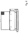
Fig. 7 is a perspective view of a detail ofFig.1 ; and -
Fig. 8 is a perspective view of a cutaway detail ofFig. 7 . - Referring now to
Fig. 1 , a bale-handling apparatus which, in the present embodiment is an apparatus for spreading bale material, has a generally rectangular, box-like shape. In use, a bale of material such as straw is inserted into thebox area 12, whereupon aconveyor belt 14 upon which the bale sits urges the bale against abale spreader head 16. Rotors of thespreader head 16 transform the bale into pieces at the same time as throwing these pieces out of the apparatus in the direction of arrow E inFig. 1 , thereby to provide a straw carpet which can be useful for animal bedding, or absorbing moisture on muddy ground, for example. The apparatus is carried upon the extended loading arm of a tractor, for example, known as a loader. Connection of the apparatus to the loader is by means of arectangular frame 20 located on the side of the apparatus, while power for the various motors operating theconveyor belt 14 androtors 16 is provided hydraulically, via the loader arm, from the tractor. - Referring now additionally to
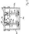
Figs. 2 to 4 , the apparatus is given structural integrity by a combination of formed sheet metal webs and steel struts. The basic structural chassis or frame of the apparatus comprises, in the present embodiment, two pairs (one pair on each longitudinal side) of, parallelhorizontal struts 24 extending along the longitudinal (i.e. the longest) sides of the rectangular box. The struts of the two longitudinal pairs are each interconnected at one end (the right hand end inFig. 2 ) to two parallel, horizontally-extendinglateral struts 26. The other ends of thelongitudinal struts 24 is the end of the apparatus adjacent thespreader head 16 and two further such lateral struts interconnect the other ends of thelongitudinal struts 24 though these are not shown in the drawings. The longitudinal andlateral struts 24, 26 (including those lateral struts not illustrated) define a basic box chassis. This box chassis is given additional structural strength, particularly against torsional loads, by means of sheet metal webs extending at various points between the pairs ofstruts strengthening support struts 30 extend in the lateral direction at the base of the box. These provide additional strength which is required for the apparatus to be carried by the loader transversely (that is to say in such a way that the spreader head operates to eject straw to the side of the loader rather than to the front). In a modification, thesupport struts 30 may be replaced with struts whose purpose is to provide structural stability, whereby theframe 20 may then be mounted by means of straps (for example of stainless steel) resulting in a lower overall weight. - A
conveyor belt 14 is located at the base of the box so that it effectively extends around thehorizontal support struts 30. This configuration enables strengthening of the base of the apparatus at the same time as avoiding an increase to any significant degree in the height (and therefore weight) of the box. The conveyor belt, illustrated in section inFig. 3 , extends around aprincipal drive roller 32 located at one end of the box, and then over a sequence ofguide rollers 34 which are journalled for rotation relative to the lowerlongitudinal struts 24. These additional support rollers ensure that no bales become 'stranded' as a result of insufficient contact with the conveyor belt; a difficulty which may more likely otherwise occur with round bales. In a modification of the illustrated design, brushes may be mounted to the apparatus to prevent extraneous material from falling into the space adjacent the rollers and potentially causing an obstruction to the motion of thebelt 14. - The end of the conveyor belt adjacent the
spreader head 16 is effectively chamfered by location of thefinal guide roller 34F below the height of the others. This facilitates easy loading of a bale into the box simply by movement of the tractor to 'scoop' a bale up from a stack of bales, known as 'self loading'. In addition, the slope provided by the chamfering reduces the likelihood of quadrant bale wafers falling backwards away from thespreader head 16, which would otherwise slow down spreading of rectangular bales. - Referring to
Fig. 2 , theprincipal drive roller 32 for thebelt 14 is adjustable laterally to enable adjustment of the tension in theconveyor belt 14; notably, thedrive roller 32 has a larger diameter than all of the other rollers, this providing a larger contact area with the belt and providing more reliable, efficient drive thereof. Theroller 32 is driven by means of a hydraulically-powered motor and reduction gearbox 40. This is shown in detail inFig. 7 and in cutaway form inFig. 8 . Themotor worm 42 meshes with agear 44 of the gearbox whose drive shaft then drives theprincipal roller 32; the arrangement being encased to avoid jamming of the gears due to contamination. Preferably, thebevel gear shaft 44 also provides the journal bearing for thedrive roller 32. This permits the use of a smaller hydraulic displacement motor which operates at a higher and more efficient speed. - Referring specifically to
Figs 1 ,3 and4 , thespreader head 16 is mounted upon a pair of forked liftingarms 50, each pivotally mounted upon an upperlongitudinal strut 24 via a bracket 52. The forked ends of the lifting arms carry the frame 60 of thespreader head 16; the frame 60 comprising pairs of vertical andlateral frame struts arms 50 are preferably made of folded sheet metal, which enables good structural strength whilst simultaneously reducing weight. Thespreader rotors 70 are carried uponrotor shafts 72, each journalled at its ends in the lateral frame struts for rotation relative to the spreader head frame 60. Elevation of the lifting arms 50 (this is done by a hydraulic actuating mechanism - not shown - and powered from the tractor hydraulic system) therefore results in a corresponding elevation of the entire spreader head 16 (that is to say the frame and the rotor shafts 72). This elevation takes place to enable loading of a new bale into the box defined by the chassis (and described above). - It will be noted that the lifting arms are mounted upon the upper part of the
longitudinal struts 24. This enables closer coupling of the apparatus to the loader by means of theframe 20, since no clearance has to be accounted for. Alternative embodiments with side mounting of the lifting arms is possible. - The
rotors 70 are concentrically mounted upon the rotor shafts 72 (seeFigs 1 ,3 and4 , for example) and comprise planar,elliptical blade holders 80, preferably manufactured from hardened steel, upon which are carried individual tines orblades 82. In the illustrated embodiment these blades are uniformly planar. In an alternative embodiment, the ends of the blades are twisted about an axis longitudinal with respect to the blade; although this increases the resistance to motion of the blade end (as a result of air resistance, amongst other things) it provides, under certain circumstances, improved performance of thespreader head 16. The degree of twist as measured at the blade tip may be between 20 and 90 degrees, examples including 30, 45, 60, 70 and 90 degrees. A further kind of blade, not illustrated, which may be useful for distributing frozen bales for example, has a body which has little or no twist and extends at 90 degrees from or close to the point of its mounting. - A cutaway view of the
spreader head 16 is shown inFig. 5 and from this themotors shafts 72. This enables mounting of rotors all the way along the shafts providing better ejection of the bale while avoiding damage to themotors motor 74 is coupled via anintermediate bearing 78 to theshaft 72 whilemotor 76 is directly mounted, showing that the motor bearing itself acts to journal the shaft, thereby saving additional weight. - Referring again to
Fig. 1 apeaked lip 100 extends above the frame 60 of the spreader head, to prevent stray elements of bale flying out at an excessively large angle. In a further modification, deflector plates may be attached to the frame to cause the ejected material to be directed in a particular direction. - The various modifications disclosed herein are not limited in their application to the embodiments in connection with which they are described and may be generally applicable to all embodiments of the invention.
Claims (7)
- Bale handling apparatus having:a box frame which retains a bale of material;a conveyor surface provided by a continuous conveyor belt (14), mounted on the box frame and upon which the bale rests, the conveyor belt (14) being operable to move the bale in a longitudinal direction towards a spreader head (16) that ejects bale material from the apparatus;the conveyor belt (14) extending around at least two rollers (32, 34F) spaced apart in the longitudinal direction;characterised in that:(a) the apparatus further comprises a rectangular frame (20) located on the side of the apparatus by means of which the apparatus may be connected to a loader and a pair of horizontal support struts (30) forming part of the box frame and extending in a lateral direction at the base of the box frame, the support struts (30) providing additional strength for the apparatus to be carried transversely by the loader, and the support struts (30) extending parallel to the rollers (32, 34F) and inside the continuum of the conveyor belt (14); and(b) a sequence of guide rollers (34) are provided within the continuum of the conveyor belt (14).
- Apparatus according to claim 1 wherein the spreader head is mounted on the frame via a pair of lifting arms, actuable to lift the spreader head and thereby enable insertion of a bale within the frame and onto the conveyor surface.
- Apparatus according to claim 2 wherein the lifting arms are mounted upon upper surfaces of the frame.
- Bale handling apparatus according to any one of the preceding claims wherein the spreader head comprises a pair of rotating shafts upon which are mounted rotors, spaced-apart along the length of the shafts, the rotors comprising an elliptical, concentrically-mounted blade holder and at least one blade extending from the blade holder.
- Bale handling apparatus according to any one of the preceding claims, wherein the spreader head is mounted to the frame via a pair of lifting arms, pivotally mounted to the frame and actuable to lift the spreader head to enable insertion of a bale in the frame.
- Apparatus according to claim 5 wherein the lifting arms are mounted upon an upper surface of the frame.
- Apparatus according to any one of the preceding claims wherein the end of the conveyor belt (14) adjacent the spreader head (16) is chamfered by location of the final guide roller (34F) below the height of the other rollers.
Applications Claiming Priority (2)
| Application Number | Priority Date | Filing Date | Title |
|---|---|---|---|
| GB201200867A GB201200867D0 (en) | 2012-01-18 | 2012-01-18 | Bale handling apparatus |
| PCT/GB2013/000019 WO2013108005A1 (en) | 2012-01-18 | 2013-01-18 | Bale handling apparatus |
Publications (2)
| Publication Number | Publication Date |
|---|---|
| EP2804465A1 EP2804465A1 (en) | 2014-11-26 |
| EP2804465B1 true EP2804465B1 (en) | 2018-05-02 |
Family
ID=45814215
Family Applications (1)
| Application Number | Title | Priority Date | Filing Date |
|---|---|---|---|
| EP13706663.5A Active EP2804465B1 (en) | 2012-01-18 | 2013-01-18 | Bale handling apparatus |
Country Status (5)
| Country | Link |
|---|---|
| EP (1) | EP2804465B1 (en) |
| DK (1) | DK2804465T3 (en) |
| ES (1) | ES2682019T3 (en) |
| GB (1) | GB201200867D0 (en) |
| WO (1) | WO2013108005A1 (en) |
Families Citing this family (4)
| Publication number | Priority date | Publication date | Assignee | Title |
|---|---|---|---|---|
| US9442526B2 (en) | 2012-05-04 | 2016-09-13 | JPMorgan Chase, Bank, N.A. | System and method for mobile device docking station |
| GB201812674D0 (en) | 2018-08-03 | 2018-09-19 | Spread A Bale Ltd | Bale handling apparatus |
| GB201907844D0 (en) | 2019-06-03 | 2019-07-17 | Spread A Bale Ltd | Bale handling apparatus |
| GB202206499D0 (en) * | 2022-05-04 | 2022-06-15 | Spread A Bale Ltd | A spreader apparatus |
Family Cites Families (6)
| Publication number | Priority date | Publication date | Assignee | Title |
|---|---|---|---|---|
| AU548889B2 (en) * | 1983-05-24 | 1986-01-09 | Boorun Pty Ltd | Hay bale feeder |
| NL8502803A (en) * | 1985-10-14 | 1987-05-04 | Lely Nv C Van Der | DEVICE AND METHOD FOR MOWING FIELD CROP. |
| GB9620701D0 (en) | 1996-10-04 | 1996-11-20 | Cestrian Inspiration Limited | Bale handling apparatus |
| FR2765773B1 (en) * | 1997-07-10 | 1999-08-27 | Abc Equip Snc | AGRICULTURAL MACHINE OF THE WASHER OR SLURRY TYPE |
| FR2865346B1 (en) * | 2004-01-23 | 2007-05-25 | Calvet Ets | DEVICE FOR DISPERSING A STRAW BALL, AND A PAILLANT FOR STRAW BALLS EQUIPPED WITH SUCH A DEVICE |
| US20060086849A1 (en) * | 2004-10-14 | 2006-04-27 | Weiss Leonard D | Bale processor |
-
2012
- 2012-01-18 GB GB201200867A patent/GB201200867D0/en not_active Ceased
-
2013
- 2013-01-18 DK DK13706663.5T patent/DK2804465T3/en active
- 2013-01-18 EP EP13706663.5A patent/EP2804465B1/en active Active
- 2013-01-18 ES ES13706663.5T patent/ES2682019T3/en active Active
- 2013-01-18 WO PCT/GB2013/000019 patent/WO2013108005A1/en active Application Filing
Non-Patent Citations (1)
| Title |
|---|
| None * |
Also Published As
| Publication number | Publication date |
|---|---|
| GB201200867D0 (en) | 2012-02-29 |
| WO2013108005A1 (en) | 2013-07-25 |
| DK2804465T3 (en) | 2018-07-30 |
| ES2682019T3 (en) | 2018-09-18 |
| EP2804465A1 (en) | 2014-11-26 |
Similar Documents
| Publication | Publication Date | Title |
|---|---|---|
| EP2804465B1 (en) | Bale handling apparatus | |
| KR101308839B1 (en) | the fowl dropping take away system | |
| CA2808751C (en) | Materials spreader | |
| US9992921B2 (en) | Aeration apparatus and methods | |
| US6572039B1 (en) | Variable mulch handling and dispersing apparatus | |
| CA2872340A1 (en) | An animal feed mixing and dispensing apparatus | |
| US7871029B2 (en) | Bale processor having improved shredding roller | |
| US20080000207A1 (en) | Crop-processing device comprising a picking-up and cutting device | |
| CA2797506C (en) | A windrow turning apparatus | |
| HUE034015T2 (en) | Agricultural machine for shredding hay, forage and similar products | |
| DE102008049557B4 (en) | Support wheelless stem receiving unit for a foliage picking vehicle | |
| EP2608654B1 (en) | Apparatus for forming a unitary bale of agricultural or forestry biomass with successive horizontally compacted layers | |
| EP2071944A2 (en) | A Machine for Treatment of Bedding in Poultry Farms | |
| EP3829290A1 (en) | Bale handling apparatus | |
| US6098387A (en) | Ground clearing apparatus | |
| RU96723U1 (en) | FEED GRINDER | |
| KR101364181B1 (en) | Baler | |
| CA2291319C (en) | Square bale processor | |
| US20020018702A1 (en) | Bale feeder | |
| CN206888045U (en) | One kind quickly collects broken forage device | |
| CN204845655U (en) | Earthing dumper | |
| WO2020245577A1 (en) | Bale handling apparatus | |
| RU126560U1 (en) | TRAILED DEVICE FOR LOADING TUKS | |
| WO2023214174A1 (en) | A spreader apparatus | |
| RU2201067C2 (en) | Feed grinder-dispenser |
Legal Events
| Date | Code | Title | Description |
|---|---|---|---|
| PUAI | Public reference made under article 153(3) epc to a published international application that has entered the european phase |
Free format text: ORIGINAL CODE: 0009012 |
|
| 17P | Request for examination filed |
Effective date: 20140811 |
|
| AK | Designated contracting states |
Kind code of ref document: A1 Designated state(s): AL AT BE BG CH CY CZ DE DK EE ES FI FR GB GR HR HU IE IS IT LI LT LU LV MC MK MT NL NO PL PT RO RS SE SI SK SM TR |
|
| DAX | Request for extension of the european patent (deleted) | ||
| STAA | Information on the status of an ep patent application or granted ep patent |
Free format text: STATUS: EXAMINATION IS IN PROGRESS |
|
| 17Q | First examination report despatched |
Effective date: 20161208 |
|
| GRAP | Despatch of communication of intention to grant a patent |
Free format text: ORIGINAL CODE: EPIDOSNIGR1 |
|
| STAA | Information on the status of an ep patent application or granted ep patent |
Free format text: STATUS: GRANT OF PATENT IS INTENDED |
|
| INTG | Intention to grant announced |
Effective date: 20171122 |
|
| GRAS | Grant fee paid |
Free format text: ORIGINAL CODE: EPIDOSNIGR3 |
|
| GRAA | (expected) grant |
Free format text: ORIGINAL CODE: 0009210 |
|
| STAA | Information on the status of an ep patent application or granted ep patent |
Free format text: STATUS: THE PATENT HAS BEEN GRANTED |
|
| AK | Designated contracting states |
Kind code of ref document: B1 Designated state(s): AL AT BE BG CH CY CZ DE DK EE ES FI FR GB GR HR HU IE IS IT LI LT LU LV MC MK MT NL NO PL PT RO RS SE SI SK SM TR |
|
| REG | Reference to a national code |
Ref country code: GB Ref legal event code: FG4D |
|
| REG | Reference to a national code |
Ref country code: CH Ref legal event code: EP Ref country code: AT Ref legal event code: REF Ref document number: 994230 Country of ref document: AT Kind code of ref document: T Effective date: 20180515 |
|
| REG | Reference to a national code |
Ref country code: DE Ref legal event code: R096 Ref document number: 602013036840 Country of ref document: DE Ref country code: IE Ref legal event code: FG4D |
|
| REG | Reference to a national code |
Ref country code: DE Ref legal event code: R096 Ref document number: 602013036840 Country of ref document: DE |
|
| REG | Reference to a national code |
Ref country code: DE Ref legal event code: R082 Ref document number: 602013036840 Country of ref document: DE Representative=s name: WUNDERLICH & HEIM PATENTANWAELTE PARTNERSCHAFT, DE |
|
| REG | Reference to a national code |
Ref country code: DK Ref legal event code: T3 Effective date: 20180723 |
|
| REG | Reference to a national code |
Ref country code: SE Ref legal event code: TRGR |
|
| REG | Reference to a national code |
Ref country code: NL Ref legal event code: FP |
|
| REG | Reference to a national code |
Ref country code: ES Ref legal event code: FG2A Ref document number: 2682019 Country of ref document: ES Kind code of ref document: T3 Effective date: 20180918 |
|
| REG | Reference to a national code |
Ref country code: LT Ref legal event code: MG4D |
|
| PG25 | Lapsed in a contracting state [announced via postgrant information from national office to epo] |
Ref country code: LT Free format text: LAPSE BECAUSE OF FAILURE TO SUBMIT A TRANSLATION OF THE DESCRIPTION OR TO PAY THE FEE WITHIN THE PRESCRIBED TIME-LIMIT Effective date: 20180502 Ref country code: FI Free format text: LAPSE BECAUSE OF FAILURE TO SUBMIT A TRANSLATION OF THE DESCRIPTION OR TO PAY THE FEE WITHIN THE PRESCRIBED TIME-LIMIT Effective date: 20180502 Ref country code: BG Free format text: LAPSE BECAUSE OF FAILURE TO SUBMIT A TRANSLATION OF THE DESCRIPTION OR TO PAY THE FEE WITHIN THE PRESCRIBED TIME-LIMIT Effective date: 20180802 Ref country code: NO Free format text: LAPSE BECAUSE OF FAILURE TO SUBMIT A TRANSLATION OF THE DESCRIPTION OR TO PAY THE FEE WITHIN THE PRESCRIBED TIME-LIMIT Effective date: 20180802 |
|
| PG25 | Lapsed in a contracting state [announced via postgrant information from national office to epo] |
Ref country code: HR Free format text: LAPSE BECAUSE OF FAILURE TO SUBMIT A TRANSLATION OF THE DESCRIPTION OR TO PAY THE FEE WITHIN THE PRESCRIBED TIME-LIMIT Effective date: 20180502 Ref country code: GR Free format text: LAPSE BECAUSE OF FAILURE TO SUBMIT A TRANSLATION OF THE DESCRIPTION OR TO PAY THE FEE WITHIN THE PRESCRIBED TIME-LIMIT Effective date: 20180803 Ref country code: LV Free format text: LAPSE BECAUSE OF FAILURE TO SUBMIT A TRANSLATION OF THE DESCRIPTION OR TO PAY THE FEE WITHIN THE PRESCRIBED TIME-LIMIT Effective date: 20180502 Ref country code: RS Free format text: LAPSE BECAUSE OF FAILURE TO SUBMIT A TRANSLATION OF THE DESCRIPTION OR TO PAY THE FEE WITHIN THE PRESCRIBED TIME-LIMIT Effective date: 20180502 |
|
| REG | Reference to a national code |
Ref country code: AT Ref legal event code: MK05 Ref document number: 994230 Country of ref document: AT Kind code of ref document: T Effective date: 20180502 |
|
| PG25 | Lapsed in a contracting state [announced via postgrant information from national office to epo] |
Ref country code: AT Free format text: LAPSE BECAUSE OF FAILURE TO SUBMIT A TRANSLATION OF THE DESCRIPTION OR TO PAY THE FEE WITHIN THE PRESCRIBED TIME-LIMIT Effective date: 20180502 Ref country code: PL Free format text: LAPSE BECAUSE OF FAILURE TO SUBMIT A TRANSLATION OF THE DESCRIPTION OR TO PAY THE FEE WITHIN THE PRESCRIBED TIME-LIMIT Effective date: 20180502 Ref country code: RO Free format text: LAPSE BECAUSE OF FAILURE TO SUBMIT A TRANSLATION OF THE DESCRIPTION OR TO PAY THE FEE WITHIN THE PRESCRIBED TIME-LIMIT Effective date: 20180502 Ref country code: SK Free format text: LAPSE BECAUSE OF FAILURE TO SUBMIT A TRANSLATION OF THE DESCRIPTION OR TO PAY THE FEE WITHIN THE PRESCRIBED TIME-LIMIT Effective date: 20180502 Ref country code: EE Free format text: LAPSE BECAUSE OF FAILURE TO SUBMIT A TRANSLATION OF THE DESCRIPTION OR TO PAY THE FEE WITHIN THE PRESCRIBED TIME-LIMIT Effective date: 20180502 |
|
| REG | Reference to a national code |
Ref country code: DE Ref legal event code: R097 Ref document number: 602013036840 Country of ref document: DE |
|
| PG25 | Lapsed in a contracting state [announced via postgrant information from national office to epo] |
Ref country code: IT Free format text: LAPSE BECAUSE OF FAILURE TO SUBMIT A TRANSLATION OF THE DESCRIPTION OR TO PAY THE FEE WITHIN THE PRESCRIBED TIME-LIMIT Effective date: 20180502 Ref country code: SM Free format text: LAPSE BECAUSE OF FAILURE TO SUBMIT A TRANSLATION OF THE DESCRIPTION OR TO PAY THE FEE WITHIN THE PRESCRIBED TIME-LIMIT Effective date: 20180502 |
|
| PLBE | No opposition filed within time limit |
Free format text: ORIGINAL CODE: 0009261 |
|
| STAA | Information on the status of an ep patent application or granted ep patent |
Free format text: STATUS: NO OPPOSITION FILED WITHIN TIME LIMIT |
|
| 26N | No opposition filed |
Effective date: 20190205 |
|
| PG25 | Lapsed in a contracting state [announced via postgrant information from national office to epo] |
Ref country code: SI Free format text: LAPSE BECAUSE OF FAILURE TO SUBMIT A TRANSLATION OF THE DESCRIPTION OR TO PAY THE FEE WITHIN THE PRESCRIBED TIME-LIMIT Effective date: 20180502 |
|
| PG25 | Lapsed in a contracting state [announced via postgrant information from national office to epo] |
Ref country code: MC Free format text: LAPSE BECAUSE OF FAILURE TO SUBMIT A TRANSLATION OF THE DESCRIPTION OR TO PAY THE FEE WITHIN THE PRESCRIBED TIME-LIMIT Effective date: 20180502 |
|
| REG | Reference to a national code |
Ref country code: CH Ref legal event code: PL |
|
| PG25 | Lapsed in a contracting state [announced via postgrant information from national office to epo] |
Ref country code: LU Free format text: LAPSE BECAUSE OF NON-PAYMENT OF DUE FEES Effective date: 20190118 |
|
| PG25 | Lapsed in a contracting state [announced via postgrant information from national office to epo] |
Ref country code: AL Free format text: LAPSE BECAUSE OF FAILURE TO SUBMIT A TRANSLATION OF THE DESCRIPTION OR TO PAY THE FEE WITHIN THE PRESCRIBED TIME-LIMIT Effective date: 20180502 |
|
| PG25 | Lapsed in a contracting state [announced via postgrant information from national office to epo] |
Ref country code: LI Free format text: LAPSE BECAUSE OF NON-PAYMENT OF DUE FEES Effective date: 20190131 Ref country code: CH Free format text: LAPSE BECAUSE OF NON-PAYMENT OF DUE FEES Effective date: 20190131 |
|
| PG25 | Lapsed in a contracting state [announced via postgrant information from national office to epo] |
Ref country code: TR Free format text: LAPSE BECAUSE OF FAILURE TO SUBMIT A TRANSLATION OF THE DESCRIPTION OR TO PAY THE FEE WITHIN THE PRESCRIBED TIME-LIMIT Effective date: 20180502 |
|
| PG25 | Lapsed in a contracting state [announced via postgrant information from national office to epo] |
Ref country code: MT Free format text: LAPSE BECAUSE OF NON-PAYMENT OF DUE FEES Effective date: 20190118 Ref country code: PT Free format text: LAPSE BECAUSE OF FAILURE TO SUBMIT A TRANSLATION OF THE DESCRIPTION OR TO PAY THE FEE WITHIN THE PRESCRIBED TIME-LIMIT Effective date: 20180903 |
|
| PG25 | Lapsed in a contracting state [announced via postgrant information from national office to epo] |
Ref country code: CY Free format text: LAPSE BECAUSE OF FAILURE TO SUBMIT A TRANSLATION OF THE DESCRIPTION OR TO PAY THE FEE WITHIN THE PRESCRIBED TIME-LIMIT Effective date: 20180502 |
|
| PG25 | Lapsed in a contracting state [announced via postgrant information from national office to epo] |
Ref country code: IS Free format text: LAPSE BECAUSE OF FAILURE TO SUBMIT A TRANSLATION OF THE DESCRIPTION OR TO PAY THE FEE WITHIN THE PRESCRIBED TIME-LIMIT Effective date: 20180902 |
|
| PG25 | Lapsed in a contracting state [announced via postgrant information from national office to epo] |
Ref country code: HU Free format text: LAPSE BECAUSE OF FAILURE TO SUBMIT A TRANSLATION OF THE DESCRIPTION OR TO PAY THE FEE WITHIN THE PRESCRIBED TIME-LIMIT; INVALID AB INITIO Effective date: 20130118 |
|
| PG25 | Lapsed in a contracting state [announced via postgrant information from national office to epo] |
Ref country code: MK Free format text: LAPSE BECAUSE OF FAILURE TO SUBMIT A TRANSLATION OF THE DESCRIPTION OR TO PAY THE FEE WITHIN THE PRESCRIBED TIME-LIMIT Effective date: 20180502 |
|
| PGFP | Annual fee paid to national office [announced via postgrant information from national office to epo] |
Ref country code: SE Payment date: 20230716 Year of fee payment: 11 Ref country code: FR Payment date: 20230716 Year of fee payment: 11 Ref country code: DK Payment date: 20230719 Year of fee payment: 11 Ref country code: BE Payment date: 20230724 Year of fee payment: 11 |
|
| PGFP | Annual fee paid to national office [announced via postgrant information from national office to epo] |
Ref country code: SE Payment date: 20230716 Year of fee payment: 11 |
|
| PGFP | Annual fee paid to national office [announced via postgrant information from national office to epo] |
Ref country code: NL Payment date: 20240125 Year of fee payment: 12 |
|
| PGFP | Annual fee paid to national office [announced via postgrant information from national office to epo] |
Ref country code: IE Payment date: 20240126 Year of fee payment: 12 Ref country code: ES Payment date: 20240228 Year of fee payment: 12 |
|
| PGFP | Annual fee paid to national office [announced via postgrant information from national office to epo] |
Ref country code: DE Payment date: 20240131 Year of fee payment: 12 Ref country code: CZ Payment date: 20240117 Year of fee payment: 12 Ref country code: GB Payment date: 20240125 Year of fee payment: 12 |