EP2804395B1 - Headphones and ear pad - Google Patents
Headphones and ear pad Download PDFInfo
- Publication number
- EP2804395B1 EP2804395B1 EP12863983.8A EP12863983A EP2804395B1 EP 2804395 B1 EP2804395 B1 EP 2804395B1 EP 12863983 A EP12863983 A EP 12863983A EP 2804395 B1 EP2804395 B1 EP 2804395B1
- Authority
- EP
- European Patent Office
- Prior art keywords
- ear
- ear pad
- pad
- headphone
- listener
- Prior art date
- Legal status (The legal status is an assumption and is not a legal conclusion. Google has not performed a legal analysis and makes no representation as to the accuracy of the status listed.)
- Active
Links
- 230000000994 depressogenic effect Effects 0.000 claims description 4
- 230000005236 sound signal Effects 0.000 claims 2
- 210000003128 head Anatomy 0.000 description 29
- 210000005069 ears Anatomy 0.000 description 7
- 230000006866 deterioration Effects 0.000 description 6
- 230000002542 deteriorative effect Effects 0.000 description 3
- 230000002238 attenuated effect Effects 0.000 description 1
- 230000015572 biosynthetic process Effects 0.000 description 1
- 230000001419 dependent effect Effects 0.000 description 1
- 230000000694 effects Effects 0.000 description 1
- 230000005489 elastic deformation Effects 0.000 description 1
- 210000001061 forehead Anatomy 0.000 description 1
- 230000001936 parietal effect Effects 0.000 description 1
Images


Classifications
-
- H—ELECTRICITY
- H04—ELECTRIC COMMUNICATION TECHNIQUE
- H04R—LOUDSPEAKERS, MICROPHONES, GRAMOPHONE PICK-UPS OR LIKE ACOUSTIC ELECTROMECHANICAL TRANSDUCERS; DEAF-AID SETS; PUBLIC ADDRESS SYSTEMS
- H04R1/00—Details of transducers, loudspeakers or microphones
- H04R1/10—Earpieces; Attachments therefor ; Earphones; Monophonic headphones
- H04R1/1058—Manufacture or assembly
-
- H—ELECTRICITY
- H04—ELECTRIC COMMUNICATION TECHNIQUE
- H04R—LOUDSPEAKERS, MICROPHONES, GRAMOPHONE PICK-UPS OR LIKE ACOUSTIC ELECTROMECHANICAL TRANSDUCERS; DEAF-AID SETS; PUBLIC ADDRESS SYSTEMS
- H04R1/00—Details of transducers, loudspeakers or microphones
- H04R1/10—Earpieces; Attachments therefor ; Earphones; Monophonic headphones
- H04R1/1008—Earpieces of the supra-aural or circum-aural type
-
- H—ELECTRICITY
- H04—ELECTRIC COMMUNICATION TECHNIQUE
- H04R—LOUDSPEAKERS, MICROPHONES, GRAMOPHONE PICK-UPS OR LIKE ACOUSTIC ELECTROMECHANICAL TRANSDUCERS; DEAF-AID SETS; PUBLIC ADDRESS SYSTEMS
- H04R1/00—Details of transducers, loudspeakers or microphones
- H04R1/10—Earpieces; Attachments therefor ; Earphones; Monophonic headphones
- H04R1/1058—Manufacture or assembly
- H04R1/1066—Constructional aspects of the interconnection between earpiece and earpiece support
-
- H—ELECTRICITY
- H04—ELECTRIC COMMUNICATION TECHNIQUE
- H04R—LOUDSPEAKERS, MICROPHONES, GRAMOPHONE PICK-UPS OR LIKE ACOUSTIC ELECTROMECHANICAL TRANSDUCERS; DEAF-AID SETS; PUBLIC ADDRESS SYSTEMS
- H04R1/00—Details of transducers, loudspeakers or microphones
- H04R1/10—Earpieces; Attachments therefor ; Earphones; Monophonic headphones
- H04R1/1058—Manufacture or assembly
- H04R1/1075—Mountings of transducers in earphones or headphones
-
- H—ELECTRICITY
- H04—ELECTRIC COMMUNICATION TECHNIQUE
- H04R—LOUDSPEAKERS, MICROPHONES, GRAMOPHONE PICK-UPS OR LIKE ACOUSTIC ELECTROMECHANICAL TRANSDUCERS; DEAF-AID SETS; PUBLIC ADDRESS SYSTEMS
- H04R5/00—Stereophonic arrangements
- H04R5/033—Headphones for stereophonic communication
- H04R5/0335—Earpiece support, e.g. headbands or neckrests
Definitions
- the present invention relates to an ear pad and a headphone comprising the same, the headphone to be connected, for example, to an audio reproducing device and used for listening to music, voice and the like.
- a headphone device including housings to be fitted respectively to the right and left ears, and a headband for connecting the housings to each other, in which the headband is attached over the head while supporting the right and left housings .
- the right and left housings each have a fitting surface to be brought into abutment on a periphery of corresponding one of the right and left ears.
- an ear pad is provided so as to allow the right and left housings to be comfortably fitted while preventing sound leakage to the surroundings and noise from an outside.
- the fitting surface to be brought into abutment on a periphery of the ear is formed to be flat.
- the fitting surface of the ear pad is flat, when the user puts on a headphone, gaps may be formed between the periphery of the ear on the head and the fitting surface of the headphone due to ridges and depressions around the ear on the head.
- there have been proposed headphones having structure in which the fitting surface of the ear pad is fitted at an angle to a periphery of the ear see Patent Literatures 1 and 2).
- JP 2003-333678 A provides a headphone in which a sound leak or deterioration of a sound quality is prevented without damaging fitness of an earpad to the ear.
- One side of a headphone main body incorporated with a speaker unit is mounted with an earpad to be fitted over the ear of a listening user.
- EP 1 921 889 A1 provides an excellent headphone which can give a more comfortable feeling and a more stable feeling to the user when being fixed to the user as compared with that in the past.
- US 4,958,697 A provides an anatomically shaped earseal for headset earcups.
- EP 1 971 181 A2 discloses a headphone including a housing that includes a speaker unit, and a protruding portion, provided at a specified area of one surface of the housing, that outputs playback sound generated from the speaker unit.
- US 2003/0007660 A1 discloses a headphone device which includes an earpad to be worn from the outside of the ear on the head, and a housing that is provided with a speaker unit as well as a fitting portion on which that earpad is fit.
- the earpad comprises a cushion and a facing that covers the cushion.
- the earpad can be attached to and detached from the housing.
- JP 2004-364210 A provides a headphone which prevents a case from floating from the ear and is convenience for improving feelings in wearing.
- the headphone comprises a case, a speaker unit, an ear pad, an ear arm, and an elastic member.
- a portion for the ear is held between the ear arm and the ear pad while handing the ear arm on the ear, so that the ear pad is fitted over a hole of ear.
- the elastic member is shaft-shaped or tube-shaped from an elastically deformable material. The elastic member is positioned between the ear and the head and abutted to the head for elastic deformation while hanging the ear arm on the ear, so that the ear pad is energized via the ear arm closer to the ear hole.
- FIG. 5 is a view as viewed from obliquely behind the head, for illustrating an example of a wearing state in which an ear pad of a related-art headphone device forms such a gap.
- a headphone device 10 including housings 20, a head pad 30, and ear pads 40
- sound leakage occurs due to gaps formed at parts from behind the ear to the neck.
- low frequency signal components of sound that the user listens to are attenuated due to the sound leakage, which may cause deterioration in sound quality.
- a gap is formed between a fitting surface of the ear pad 40 and a periphery of the ear, which also causes problems of sound leakage and deterioration in sound quality.
- the present invention provides an ear pad according to Claim 1.
- a headphone according to dependent claims 3-5 comprising an ear pad according to independent claim 1.
- the ear pad of the headphone can be fitted without gaps or without deteriorating wearing comfort of the headphone, to thereby prevent sound leakage. Further, deterioration in sound quality, which may be caused by the sound leakage, can also be prevented.
- FIG. 1 is a view illustrating a schematic configuration of a headphone device according to an embodiment of the present invention.
- the headphone device to be used for listening to music, voice, and the like while being attached over the head and fitted to the right and left ears of a user
- right and left housings 1 respectively receive built-in speaker drivers (not shown), and include ear pads 2 to be fitted respectively to the right and left ears.
- Pipes 3 and a head pad 4 serve as a head band, and connect the right and left housings 1 to each other.
- the head pad 4 includes therein a cushion member (not shown) so that the headphone device is attached over and supported by the parietal region of the user.
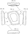
- FIGS. 2 are views illustrating a shape of the left ear pad of the headphone device according to the embodiment of the present invention.
- FIG. 2(a) is a top view
- FIG. 2(b) is a rear view
- FIG. 2(c) is a front view of a fitting surface
- FIG. 2(d) is a front view
- FIG. 2(e) is a bottom view.
- FIGS. 3 are views illustrating a shape of the right ear pad of the headphone device according to the embodiment of the present invention.
- FIG. 3(a) is a top view
- FIG. 3(b) is a front view
- FIG. 3 (c) is a front view of a fitting surface
- FIG. 3 (d) is a rear view
- FIG. 3(e) is a bottom view.
- the right and left housings are each formed into a substantially hexagonal shape, and the fitting surfaces thereof are formed into a curved surface having protrusions and depressions for closing gaps at the time of fitting.
- a smooth protruding portion (see part (1) in FIGS. 2 and 3 ) is formed at a part corresponding to the lower rear part of the ear on the head so as to be softly fitted to the lower rear part of the ear of the user (lower left part in FIG. 2(c) , and lower right part in FIG. 3(c) ).
- a smooth protruding portion (see part (2) in FIGS. 2 and 3 ) is formed at a part corresponding to the upper front part of the ear on the head so that the ear pad is softly fitted to the upper front part of the ear of the user (upper left part in FIG. 2(c) , and upper right part in FIG. 3(c) ).
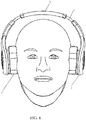
- FIG. 4 is a view of a wearing state of the headphone device as viewed from the front of the head.
- protrusions and depressions (curved-surface shape) of the ear pads are fitted to peripheries of the ears on the head.
- boundaries of the head and the ear pads are brought into close contact with each other. As a result, sound leakage can be prevented.
- the ear pads illustrated in FIGS. 2 and 3 are each formed into a substantially rounded hexagonal shape.
- rounded corners A to F are formed.
- rounded corners G to L are formed.
- an upper front side (A-B in FIG. 2 (c) and G-H in FIG. 3(c) ) is formed into a slope along which the fitting surface swells from top to bottom.
- a lower front side (B-C in FIG. 2(c) and H-I in FIG. 3(c) ) is formed into a substantially flat surface along which the fitting surface slightly shrinks from top to bottom.
- the corner B in FIG. 2(c) and the corner H in FIG. 3(c) each form a peak of the protruding portion on the fitting surface.
- a lower side (C-D in FIG. 2(c) and I-J in FIG. 3(c) ) is formed into a slope along which the fitting surface gently swells from front to rear.
- a lower rear side (D-E in FIG. 2(c) and J-K in FIG. 3(c) ) is formed into a slope along which the fitting surface gently shrinks from bottom to top. Meanwhile, the corner D in FIG. 2(c) and the corner J in FIG. 3(c) each form a peak of the protruding portion on the fitting surface.
- an upper rear side (E-F in FIG. 2 (c) and K-L in FIG. 3(c) ) is formed into a slope along which the fitting surface gently swells from bottom to top.
- the corner E in FIG. 2(c) and the corner K in FIG. 3(c) each form a bottom peak of a valley of a depressed portion on the fitting surface.
- the corner F in FIG. 2(c) and the corner L in FIG. 3(c) each form a peak of the protruding portion on the fitting surface.
- an upper side (F-A in FIG. 2(c) and L-G in FIG. 3(c) ) is formed into a slope along which the fitting surface gently shrinks from rear to front. Meanwhile, the corner A in FIG. 2(c) and the corner G in FIG. 3(c) each form a bottom peak of a valley of a depressed portion on the fitting surface.
- a curved surface having protrusions and depressions is formed as a fitting surface of an elastic ear pad.
- the fitting surface can be fitted to the periphery of the ear on the head of a user.
- each side of a surface of the ear pad which is held in contact with the head of the user, is inclined to be an upward or downward monotonic slope. Turning points from an upward direction to a downward direction, turning points from the downward direction to the upward direction, or turning points between inclination angles are provided correspondingly to the corner portions of the ear pad.
- components of the ear pad can be separately manufactured into a simple shape, and assembled to each other.
- ear pads having a fitting surface including complicated protrusions and depressions that are easily fitted to the periphery of the ear of the user can be produced and assembled easily and at low cost.
- the present invention is applicable to ear pads having an easy-to-fit shape, and also to comfortable headphones including the ear pads.
Description
- The present invention relates to an ear pad and a headphone comprising the same, the headphone to be connected, for example, to an audio reproducing device and used for listening to music, voice and the like.
- As an example of headphone devices to be used for listening to music, voice, and the like while being attached over the head and fitted to the right and left ears of a user, there has been generally known a headphone device including housings to be fitted respectively to the right and left ears, and a headband for connecting the housings to each other, in which the headband is attached over the head while supporting the right and left housings .
- The right and left housings each have a fitting surface to be brought into abutment on a periphery of corresponding one of the right and left ears. On the fitting surface, an ear pad is provided so as to allow the right and left housings to be comfortably fitted while preventing sound leakage to the surroundings and noise from an outside.
- In many types of the ear pads to be used for headphones, the fitting surface to be brought into abutment on a periphery of the ear is formed to be flat. In a case where the fitting surface of the ear pad is flat, when the user puts on a headphone, gaps may be formed between the periphery of the ear on the head and the fitting surface of the headphone due to ridges and depressions around the ear on the head. In order to close the gaps, there have been proposed headphones having structure in which the fitting surface of the ear pad is fitted at an angle to a periphery of the ear (see
Patent Literatures 1 and 2). -
- [PTL 1]
JP 05-085190 U - [PTL 2]
JP 2008-124734 A -
JP 2003-333678 A -
EP 1 921 889 A1 -
US 4,958,697 A provides an anatomically shaped earseal for headset earcups. -
EP 1 971 181 A2 -
US 2003/0007660 A1 discloses a headphone device which includes an earpad to be worn from the outside of the ear on the head, and a housing that is provided with a speaker unit as well as a fitting portion on which that earpad is fit. The earpad comprises a cushion and a facing that covers the cushion. The earpad can be attached to and detached from the housing. By means of making it possible to detach the facing from the cushion as well, a headphone device can be obtained in which that earpad can be kept clean and that have improve hygiene. -
JP 2004-364210 A - The structure in which the fitting surface of the ear pad is fitted at an angle as disclosed in
Patent Literatures FIG. 5 is a view as viewed from obliquely behind the head, for illustrating an example of a wearing state in which an ear pad of a related-art headphone device forms such a gap. Specifically, as in the example of the figure, under a state in which a user wears aheadphone device 10 includinghousings 20, ahead pad 30, andear pads 40, sound leakage occurs due to gaps formed at parts from behind the ear to the neck. Further, low frequency signal components of sound that the user listens to are attenuated due to the sound leakage, which may cause deterioration in sound quality. Also at other parts such as an upper front part of the ear, a gap is formed between a fitting surface of theear pad 40 and a periphery of the ear, which also causes problems of sound leakage and deterioration in sound quality. - It is therefore an object of the present invention to provide a headphone capable of preventing a fitting surface of an ear pad from forming gaps without deteriorating wearing comfort at the time of wearing the headphone so as to prevent sound leakage to an outside and deterioration in sound quality, such as lack of sound pressure in a low frequency band of sound that a user listens to. Further, it is another object of the present invention to provide an ear pad having a structure capable of easily forming protrusions and depressions for preventing a fitting surface of a headphone from forming gaps.
- In a first aspect, the present invention provides an ear pad according to
Claim 1. - Also disclosed herein is a headphone according to dependent claims 3-5, comprising an ear pad according to
independent claim 1. - According to the headphone and the ear pad of the embodiment of the present invention, the ear pad of the headphone can be fitted without gaps or without deteriorating wearing comfort of the headphone, to thereby prevent sound leakage. Further, deterioration in sound quality, which may be caused by the sound leakage, can also be prevented.
-
-
FIG. 1 is a view illustrating a schematic configuration of a headphone device according to the embodiment of the present invention. -
FIGS. 2 are views illustrating a shape of a left ear pad of the headphone device according to the embodiment of the present invention. -
FIGS. 3 are views illustrating a shape of a right ear pad of the headphone device according to the embodiment of the present invention. -
FIG. 4 is a view of a wearing state in which the ear pads of the headphone device are fitted in close contact with the head. -
FIG. 5 is a view of an example of a wearing state in which an ear pad of a related-art headphone device forms a gap. -
FIG. 1 is a view illustrating a schematic configuration of a headphone device according to an embodiment of the present invention. In the headphone device to be used for listening to music, voice, and the like while being attached over the head and fitted to the right and left ears of a user, right andleft housings 1 respectively receive built-in speaker drivers (not shown), and includeear pads 2 to be fitted respectively to the right and left ears. -
Pipes 3 and ahead pad 4 serve as a head band, and connect the right andleft housings 1 to each other. Thehead pad 4 includes therein a cushion member (not shown) so that the headphone device is attached over and supported by the parietal region of the user. -
FIGS. 2 are views illustrating a shape of the left ear pad of the headphone device according to the embodiment of the present invention.FIG. 2(a) is a top view,FIG. 2(b) is a rear view,FIG. 2(c) is a front view of a fitting surface,FIG. 2(d) is a front view, andFIG. 2(e) is a bottom view. -
FIGS. 3 are views illustrating a shape of the right ear pad of the headphone device according to the embodiment of the present invention.FIG. 3(a) is a top view,FIG. 3(b) is a front view,FIG. 3 (c) is a front view of a fitting surface,FIG. 3 (d) is a rear view, andFIG. 3(e) is a bottom view. - The right and left housings are each formed into a substantially hexagonal shape, and the fitting surfaces thereof are formed into a curved surface having protrusions and depressions for closing gaps at the time of fitting.
- When a flat ear pad is fitted, around the ear of the listener, gaps tend to be formed at a lower rear part of the ear on the head due to depressions at the base of the neck. As a measure therefor, on the fitting surface of the ear pad, a smooth protruding portion (see part (1) in
FIGS. 2 and3 ) is formed at a part corresponding to the lower rear part of the ear on the head so as to be softly fitted to the lower rear part of the ear of the user (lower left part inFIG. 2(c) , and lower right part inFIG. 3(c) ). - Around the ear of the listener, gaps tend to be formed at an upper front part of the ear on the head due to depressions that are formed by a temple part on a lateral side of the forehead and a cheek part. As a measure therefor, on the fitting surface of the ear pad, a smooth protruding portion (see part (2) in
FIGS. 2 and3 ) is formed at a part corresponding to the upper front part of the ear on the head so that the ear pad is softly fitted to the upper front part of the ear of the user (upper left part inFIG. 2(c) , and upper right part inFIG. 3(c) ). - When the protruding portion is formed on such ear pads at the part corresponding to the lower rear part or the upper front part of the ear of the user, gaps between the ear pads and the head can be closed without deteriorating wearing comfort of the headphones . As a result, sound leakage can be prevented.
-
FIG. 4 is a view of a wearing state of the headphone device as viewed from the front of the head. There are ridges and depressions around the ears on the head. Thus, when the headphone device is attached to the head, protrusions and depressions (curved-surface shape) of the ear pads are fitted to peripheries of the ears on the head. With this, as illustrated inFIG. 4 , boundaries of the head and the ear pads are brought into close contact with each other. As a result, sound leakage can be prevented. - The ear pads illustrated in
FIGS. 2 and3 are each formed into a substantially rounded hexagonal shape. InFIG. 2(c) , rounded corners A to F are formed. InFIG. 3(c) , rounded corners G to L are formed. - In each of the ear pads illustrated in
FIGS. 2 and3 , an upper front side (A-B inFIG. 2 (c) and G-H inFIG. 3(c) ) is formed into a slope along which the fitting surface swells from top to bottom. Further, a lower front side (B-C inFIG. 2(c) and H-I inFIG. 3(c) ) is formed into a substantially flat surface along which the fitting surface slightly shrinks from top to bottom. Meanwhile, the corner B inFIG. 2(c) and the corner H inFIG. 3(c) each form a peak of the protruding portion on the fitting surface. - In each of the ear pads illustrated in
FIGS. 2 and3 , a lower side (C-D inFIG. 2(c) and I-J inFIG. 3(c) ) is formed into a slope along which the fitting surface gently swells from front to rear. - In each of the ear pads illustrated in
FIGS. 2 and3 , a lower rear side (D-E inFIG. 2(c) and J-K inFIG. 3(c) ) is formed into a slope along which the fitting surface gently shrinks from bottom to top. Meanwhile, the corner D inFIG. 2(c) and the corner J inFIG. 3(c) each form a peak of the protruding portion on the fitting surface. - In each of the ear pads illustrated in
FIGS. 2 and3 , an upper rear side (E-F inFIG. 2 (c) and K-L inFIG. 3(c) ) is formed into a slope along which the fitting surface gently swells from bottom to top. Meanwhile, the corner E inFIG. 2(c) and the corner K inFIG. 3(c) each form a bottom peak of a valley of a depressed portion on the fitting surface. The corner F inFIG. 2(c) and the corner L inFIG. 3(c) each form a peak of the protruding portion on the fitting surface. - In each of the ear pads illustrated in
FIGS. 2 and3 , an upper side (F-A inFIG. 2(c) and L-G inFIG. 3(c) ) is formed into a slope along which the fitting surface gently shrinks from rear to front. Meanwhile, the corner A inFIG. 2(c) and the corner G inFIG. 3(c) each form a bottom peak of a valley of a depressed portion on the fitting surface. - With the ear pad configuration as illustrated in
FIGS. 2 and3 , a curved surface having protrusions and depressions is formed as a fitting surface of an elastic ear pad. With this, the fitting surface can be fitted to the periphery of the ear on the head of a user. - Thus, formation of gaps can be prevented between the periphery of the ear on the head of the user and the ear pad. With this, as illustrated in
FIG. 4 , boundaries of the head and the ear pads are fitted to each other. As a result, sound leakage and deterioration in sound quality can be prevented. - As described above, each side of a surface of the ear pad, which is held in contact with the head of the user, is inclined to be an upward or downward monotonic slope. Turning points from an upward direction to a downward direction, turning points from the downward direction to the upward direction, or turning points between inclination angles are provided correspondingly to the corner portions of the ear pad. With this, components of the ear pad can be separately manufactured into a simple shape, and assembled to each other. As a result, ear pads having a fitting surface including complicated protrusions and depressions that are easily fitted to the periphery of the ear of the user can be produced and assembled easily and at low cost.
- The present invention is applicable to ear pads having an easy-to-fit shape, and also to comfortable headphones including the ear pads.
-
- 1
- housing
- 2
- ear pad
- 3
- pipe
- 4
- head pad
Claims (5)
- An ear pad (2) configured to be fitted onto a surface of a housing (1) of a headphone, the ear pad to be brought into abutment on an ear of a listener, the housing comprising a built-in speaker driver for outputting an audio signal as sound,wherein when the ear pad is in use, a surface of the ear pad is brought into abutment around the periphery of the listener's ear, andwherein the surface of the ear pad is not flat and the ear pad comprises a first protruding portion on the surface, which is to be brought into abutment around an upper front part of the periphery of the ear of the listener, and a second protruding portion on the surface, which is to be brought into abutment around a lower rear part of the periphery of the ear of the listener,characterized in that the ear pad consists of six segments arranged around the housing and which together surround the listener's ear, wherein the six segments are as follows:and wherein the segments swell or shrink in the following directions:an upper front side (A-B and G-H);a lower front side (B-C and H-I);a lower side (C-D and I-J);a lower rear side (D-E and J-K);an upper rear side (E-F and K-L);an upper side (F-A and L-G);the upper front side (A-B and G-H) swells from top to bottom;the lower front side (B-C and H-I) shrinks from top to bottom;the lower side (C-D and I-J) swells from front to rear;the lower rear side (D-E and J-K) shrinks from bottom to top;the upper rear side (E-F and K-L) swells from bottom to top;the upper side (F-A and L-G) shrinks from rear to front;such that the surface of the ear pad on each segment is a monotonic slope and turning points between the slopes occur at corner portions of the ear pad between each segment;and wherein in this claim the terms 'front', 'rear', 'upper' and 'lower' are all described in relation to the orientation of the ear pad when located on the listener' s head, and the terms 'swell' and 'shrink' are described in relation to the thickness of the ear pad.
- An ear pad (2) according to claim 1 wherein:a corner (B and H) between the upper front side and lower front side forms a peak of the first protruding portion on the surface of the ear pad;a corner (D and J) between the lower side and lower rear side forms a peak of the second protruding portion on the surface of the ear pad;a corner (E and K) between the lower rear side and upper rear side forms a bottom peak of a valley of a first depressed portion on the surface of the ear pad;a corner (F and L) between the upper rear side and upper side forms a peak of a third protruding portion on the surface of the ear pad; anda corner (A and G) between the upper side and upper front side forms a bottom peak of a valley of a second depressed portion on the surface of the ear pad.
- A headphone, comprising an ear pad (2) according to claim 1 or claim 2, the ear pad fitted onto a surface of a housing (1), the housing comprising a built-in speaker driver for outputting an audio signal as sound,wherein when the headphone is in use, a surface of the ear pad is brought into abutment around the periphery of the listener's ear.
- A headphone according to claim 3, wherein the ear pad is formed into a polygonal shape.
- A headphone according to claim 3 or 4, the headphone including a pair of housings each with an ear pad thereon, wherein the second ear pad has the same features as the first ear pad.
Applications Claiming Priority (2)
| Application Number | Priority Date | Filing Date | Title |
|---|---|---|---|
| JP2011288541A JP2013138350A (en) | 2011-12-28 | 2011-12-28 | Headphones and ear pads |
| PCT/JP2012/081029 WO2013099516A1 (en) | 2011-12-28 | 2012-11-30 | Headphones and ear pad |
Publications (3)
| Publication Number | Publication Date |
|---|---|
| EP2804395A1 EP2804395A1 (en) | 2014-11-19 |
| EP2804395A4 EP2804395A4 (en) | 2015-08-19 |
| EP2804395B1 true EP2804395B1 (en) | 2018-04-18 |
Family
ID=48697014
Family Applications (1)
| Application Number | Title | Priority Date | Filing Date |
|---|---|---|---|
| EP12863983.8A Active EP2804395B1 (en) | 2011-12-28 | 2012-11-30 | Headphones and ear pad |
Country Status (4)
| Country | Link |
|---|---|
| US (1) | US9473844B2 (en) |
| EP (1) | EP2804395B1 (en) |
| JP (1) | JP2013138350A (en) |
| WO (1) | WO2013099516A1 (en) |
Families Citing this family (7)
| Publication number | Priority date | Publication date | Assignee | Title |
|---|---|---|---|---|
| GB2527157B (en) * | 2014-11-19 | 2016-07-13 | Kokoon Tech Ltd | A headphone |
| WO2016181531A1 (en) | 2015-05-13 | 2016-11-17 | Omotenasy合同会社 | Headphones |
| US20190215593A1 (en) * | 2018-01-11 | 2019-07-11 | Te-Sheng LIU | Highly-Closed Headphone Apparatus with Wearing Comfort |
| USD913598S1 (en) * | 2019-01-31 | 2021-03-16 | INVISIO Communications A/S | Headset |
| US11902730B2 (en) * | 2019-01-31 | 2024-02-13 | Invisio A/S | Cushion configured to be secured to an ear cup of a headset and/or hearing protection device |
| USD1013282S1 (en) * | 2020-12-07 | 2024-01-30 | Alpine Nederland B.V. | Earmuffs |
| USD978444S1 (en) * | 2021-06-17 | 2023-02-14 | Zubang Chen | Electronic earmuff |
Citations (2)
| Publication number | Priority date | Publication date | Assignee | Title |
|---|---|---|---|---|
| US20030007660A1 (en) * | 2000-01-07 | 2003-01-09 | Naotaka Tsunoda | Headphone device |
| JP2004364210A (en) * | 2003-06-09 | 2004-12-24 | Sony Corp | Headphone |
Family Cites Families (24)
| Publication number | Priority date | Publication date | Assignee | Title |
|---|---|---|---|---|
| US2856469A (en) * | 1955-12-05 | 1958-10-14 | Morse Milton | Earphone barrier device |
| US3602329A (en) * | 1970-01-07 | 1971-08-31 | Columbia Broadcasting Systems | Conformal ear enclosure |
| JPS5148996Y2 (en) * | 1974-09-20 | 1976-11-26 | ||
| JPS5831182B2 (en) | 1975-03-27 | 1983-07-04 | 住友ベークライト株式会社 | Kashyokusei Film no Seizouhouhou |
| JPS51112533U (en) * | 1975-03-07 | 1976-09-11 | ||
| JPS52133627U (en) * | 1976-04-07 | 1977-10-11 | ||
| JPS52133627A (en) | 1976-04-24 | 1977-11-09 | Jidosha Kiki Co Ltd | Steering booster |
| AT355646B (en) * | 1977-02-02 | 1980-03-10 | Akg Akustische Kino Geraete | HEADPHONES FOR IMPROVED SPATIAL HEARINGS |
| US4117864A (en) | 1977-09-15 | 1978-10-03 | The Bendix Corporation | Power steering control valve |
| JPS5453428U (en) * | 1977-09-21 | 1979-04-13 | ||
| US4958697A (en) * | 1989-09-11 | 1990-09-25 | The United States Of America As Represented By The Secretary Of The Army | Anatomically shaped earseals for headsets |
| JP2607559Y2 (en) | 1992-04-17 | 2001-11-12 | 株式会社オーディオテクニカ | Earpad detachable headphones |
| JPH08307983A (en) * | 1995-05-11 | 1996-11-22 | Sony Corp | Inside phone |
| US6148446A (en) * | 1999-05-06 | 2000-11-21 | Bacou Usa Safety, Inc. | Multi-position banded earmuff |
| JP3865653B2 (en) * | 2002-05-14 | 2007-01-10 | シャープ株式会社 | headphone |
| US7114823B2 (en) * | 2002-07-19 | 2006-10-03 | Mccullough Wayne | Illumination systems and methods of use |
| JP4548783B2 (en) * | 2005-07-08 | 2010-09-22 | Necトーキン株式会社 | headphone |
| JP4899810B2 (en) * | 2006-11-10 | 2012-03-21 | ソニー株式会社 | Headphones and ear pads |
| JP2008193609A (en) | 2007-02-07 | 2008-08-21 | Audio Technica Corp | Headphone unit and headphone |
| JP4946538B2 (en) * | 2007-03-13 | 2012-06-06 | ソニー株式会社 | Headphone device |
| JP5082764B2 (en) * | 2007-10-25 | 2012-11-28 | ソニー株式会社 | Earpad and headphone device |
| US8374373B2 (en) * | 2008-11-26 | 2013-02-12 | Bose Corporation | High transmission loss headphone cushion |
| JP2012054780A (en) | 2010-09-01 | 2012-03-15 | Sony Corp | Ear pad |
| JP2012160787A (en) * | 2011-01-28 | 2012-08-23 | Sony Corp | Ear pad |
-
2011
- 2011-12-28 JP JP2011288541A patent/JP2013138350A/en active Pending
-
2012
- 2012-11-30 EP EP12863983.8A patent/EP2804395B1/en active Active
- 2012-11-30 US US14/370,946 patent/US9473844B2/en active Active
- 2012-11-30 WO PCT/JP2012/081029 patent/WO2013099516A1/en active Application Filing
Patent Citations (2)
| Publication number | Priority date | Publication date | Assignee | Title |
|---|---|---|---|---|
| US20030007660A1 (en) * | 2000-01-07 | 2003-01-09 | Naotaka Tsunoda | Headphone device |
| JP2004364210A (en) * | 2003-06-09 | 2004-12-24 | Sony Corp | Headphone |
Also Published As
| Publication number | Publication date |
|---|---|
| EP2804395A1 (en) | 2014-11-19 |
| US9473844B2 (en) | 2016-10-18 |
| US20150281828A1 (en) | 2015-10-01 |
| WO2013099516A1 (en) | 2013-07-04 |
| EP2804395A4 (en) | 2015-08-19 |
| JP2013138350A (en) | 2013-07-11 |
Similar Documents
| Publication | Publication Date | Title |
|---|---|---|
| EP2804395B1 (en) | Headphones and ear pad | |
| JP5367658B2 (en) | Ear speaker | |
| WO2022022618A1 (en) | Earphone | |
| US8781570B2 (en) | Audio headset with bio-signal sensors | |
| US20170339481A1 (en) | Earpiece system | |
| JP6408243B2 (en) | Ear proximity speaker device | |
| JP5910119B2 (en) | headphone | |
| TWI572215B (en) | Earphone structure | |
| JPWO2007069784A1 (en) | Bone conduction receiver | |
| CN102150437A (en) | Ear hook headphones | |
| JP6032499B2 (en) | Sealed headphones | |
| WO2016151952A1 (en) | Wearable device | |
| US20170118548A1 (en) | Eartip and earphone device using the same | |
| JP2010252132A (en) | Stereo earphone | |
| JP2009060348A (en) | Headphone | |
| JP2020036209A (en) | Bone conduction headset | |
| JP4867976B2 (en) | Headphone device | |
| KR20160060345A (en) | The head pad for headset | |
| JP2020036210A (en) | Bone conduction microphone | |
| WO2016070065A1 (en) | Earpiece system | |
| EP3213528A1 (en) | Earpiece system | |
| JPH04216299A (en) | Headphone | |
| JP5035462B2 (en) | Headphone device | |
| JP2010226645A (en) | Headphone | |
| CN116569565A (en) | Edge, speaker unit, microphone, and acoustic processing device |
Legal Events
| Date | Code | Title | Description |
|---|---|---|---|
| PUAI | Public reference made under article 153(3) epc to a published international application that has entered the european phase |
Free format text: ORIGINAL CODE: 0009012 |
|
| 17P | Request for examination filed |
Effective date: 20140711 |
|
| AK | Designated contracting states |
Kind code of ref document: A1 Designated state(s): AL AT BE BG CH CY CZ DE DK EE ES FI FR GB GR HR HU IE IS IT LI LT LU LV MC MK MT NL NO PL PT RO RS SE SI SK SM TR |
|
| DAX | Request for extension of the european patent (deleted) | ||
| RA4 | Supplementary search report drawn up and despatched (corrected) |
Effective date: 20150717 |
|
| RIC1 | Information provided on ipc code assigned before grant |
Ipc: H04R 5/033 20060101ALI20150713BHEP Ipc: H04R 1/10 20060101AFI20150713BHEP |
|
| 17Q | First examination report despatched |
Effective date: 20160621 |
|
| GRAP | Despatch of communication of intention to grant a patent |
Free format text: ORIGINAL CODE: EPIDOSNIGR1 |
|
| INTG | Intention to grant announced |
Effective date: 20171219 |
|
| GRAS | Grant fee paid |
Free format text: ORIGINAL CODE: EPIDOSNIGR3 |
|
| GRAA | (expected) grant |
Free format text: ORIGINAL CODE: 0009210 |
|
| AK | Designated contracting states |
Kind code of ref document: B1 Designated state(s): AL AT BE BG CH CY CZ DE DK EE ES FI FR GB GR HR HU IE IS IT LI LT LU LV MC MK MT NL NO PL PT RO RS SE SI SK SM TR |
|
| REG | Reference to a national code |
Ref country code: GB Ref legal event code: FG4D |
|
| REG | Reference to a national code |
Ref country code: CH Ref legal event code: EP |
|
| REG | Reference to a national code |
Ref country code: AT Ref legal event code: REF Ref document number: 991681 Country of ref document: AT Kind code of ref document: T Effective date: 20180515 |
|
| REG | Reference to a national code |
Ref country code: IE Ref legal event code: FG4D |
|
| REG | Reference to a national code |
Ref country code: DE Ref legal event code: R096 Ref document number: 602012045470 Country of ref document: DE |
|
| REG | Reference to a national code |
Ref country code: NL Ref legal event code: MP Effective date: 20180418 |
|
| REG | Reference to a national code |
Ref country code: LT Ref legal event code: MG4D |
|
| PG25 | Lapsed in a contracting state [announced via postgrant information from national office to epo] |
Ref country code: NL Free format text: LAPSE BECAUSE OF FAILURE TO SUBMIT A TRANSLATION OF THE DESCRIPTION OR TO PAY THE FEE WITHIN THE PRESCRIBED TIME-LIMIT Effective date: 20180418 |
|
| PG25 | Lapsed in a contracting state [announced via postgrant information from national office to epo] |
Ref country code: PL Free format text: LAPSE BECAUSE OF FAILURE TO SUBMIT A TRANSLATION OF THE DESCRIPTION OR TO PAY THE FEE WITHIN THE PRESCRIBED TIME-LIMIT Effective date: 20180418 Ref country code: SE Free format text: LAPSE BECAUSE OF FAILURE TO SUBMIT A TRANSLATION OF THE DESCRIPTION OR TO PAY THE FEE WITHIN THE PRESCRIBED TIME-LIMIT Effective date: 20180418 Ref country code: ES Free format text: LAPSE BECAUSE OF FAILURE TO SUBMIT A TRANSLATION OF THE DESCRIPTION OR TO PAY THE FEE WITHIN THE PRESCRIBED TIME-LIMIT Effective date: 20180418 Ref country code: LT Free format text: LAPSE BECAUSE OF FAILURE TO SUBMIT A TRANSLATION OF THE DESCRIPTION OR TO PAY THE FEE WITHIN THE PRESCRIBED TIME-LIMIT Effective date: 20180418 Ref country code: NO Free format text: LAPSE BECAUSE OF FAILURE TO SUBMIT A TRANSLATION OF THE DESCRIPTION OR TO PAY THE FEE WITHIN THE PRESCRIBED TIME-LIMIT Effective date: 20180718 Ref country code: AL Free format text: LAPSE BECAUSE OF FAILURE TO SUBMIT A TRANSLATION OF THE DESCRIPTION OR TO PAY THE FEE WITHIN THE PRESCRIBED TIME-LIMIT Effective date: 20180418 Ref country code: BG Free format text: LAPSE BECAUSE OF FAILURE TO SUBMIT A TRANSLATION OF THE DESCRIPTION OR TO PAY THE FEE WITHIN THE PRESCRIBED TIME-LIMIT Effective date: 20180718 Ref country code: FI Free format text: LAPSE BECAUSE OF FAILURE TO SUBMIT A TRANSLATION OF THE DESCRIPTION OR TO PAY THE FEE WITHIN THE PRESCRIBED TIME-LIMIT Effective date: 20180418 |
|
| PG25 | Lapsed in a contracting state [announced via postgrant information from national office to epo] |
Ref country code: LV Free format text: LAPSE BECAUSE OF FAILURE TO SUBMIT A TRANSLATION OF THE DESCRIPTION OR TO PAY THE FEE WITHIN THE PRESCRIBED TIME-LIMIT Effective date: 20180418 Ref country code: RS Free format text: LAPSE BECAUSE OF FAILURE TO SUBMIT A TRANSLATION OF THE DESCRIPTION OR TO PAY THE FEE WITHIN THE PRESCRIBED TIME-LIMIT Effective date: 20180418 Ref country code: HR Free format text: LAPSE BECAUSE OF FAILURE TO SUBMIT A TRANSLATION OF THE DESCRIPTION OR TO PAY THE FEE WITHIN THE PRESCRIBED TIME-LIMIT Effective date: 20180418 Ref country code: GR Free format text: LAPSE BECAUSE OF FAILURE TO SUBMIT A TRANSLATION OF THE DESCRIPTION OR TO PAY THE FEE WITHIN THE PRESCRIBED TIME-LIMIT Effective date: 20180719 |
|
| REG | Reference to a national code |
Ref country code: AT Ref legal event code: MK05 Ref document number: 991681 Country of ref document: AT Kind code of ref document: T Effective date: 20180418 |
|
| PG25 | Lapsed in a contracting state [announced via postgrant information from national office to epo] |
Ref country code: PT Free format text: LAPSE BECAUSE OF FAILURE TO SUBMIT A TRANSLATION OF THE DESCRIPTION OR TO PAY THE FEE WITHIN THE PRESCRIBED TIME-LIMIT Effective date: 20180820 |
|
| REG | Reference to a national code |
Ref country code: DE Ref legal event code: R097 Ref document number: 602012045470 Country of ref document: DE |
|
| PG25 | Lapsed in a contracting state [announced via postgrant information from national office to epo] |
Ref country code: DK Free format text: LAPSE BECAUSE OF FAILURE TO SUBMIT A TRANSLATION OF THE DESCRIPTION OR TO PAY THE FEE WITHIN THE PRESCRIBED TIME-LIMIT Effective date: 20180418 Ref country code: SK Free format text: LAPSE BECAUSE OF FAILURE TO SUBMIT A TRANSLATION OF THE DESCRIPTION OR TO PAY THE FEE WITHIN THE PRESCRIBED TIME-LIMIT Effective date: 20180418 Ref country code: EE Free format text: LAPSE BECAUSE OF FAILURE TO SUBMIT A TRANSLATION OF THE DESCRIPTION OR TO PAY THE FEE WITHIN THE PRESCRIBED TIME-LIMIT Effective date: 20180418 Ref country code: CZ Free format text: LAPSE BECAUSE OF FAILURE TO SUBMIT A TRANSLATION OF THE DESCRIPTION OR TO PAY THE FEE WITHIN THE PRESCRIBED TIME-LIMIT Effective date: 20180418 Ref country code: RO Free format text: LAPSE BECAUSE OF FAILURE TO SUBMIT A TRANSLATION OF THE DESCRIPTION OR TO PAY THE FEE WITHIN THE PRESCRIBED TIME-LIMIT Effective date: 20180418 Ref country code: AT Free format text: LAPSE BECAUSE OF FAILURE TO SUBMIT A TRANSLATION OF THE DESCRIPTION OR TO PAY THE FEE WITHIN THE PRESCRIBED TIME-LIMIT Effective date: 20180418 |
|
| PLBE | No opposition filed within time limit |
Free format text: ORIGINAL CODE: 0009261 |
|
| STAA | Information on the status of an ep patent application or granted ep patent |
Free format text: STATUS: NO OPPOSITION FILED WITHIN TIME LIMIT |
|
| PG25 | Lapsed in a contracting state [announced via postgrant information from national office to epo] |
Ref country code: IT Free format text: LAPSE BECAUSE OF FAILURE TO SUBMIT A TRANSLATION OF THE DESCRIPTION OR TO PAY THE FEE WITHIN THE PRESCRIBED TIME-LIMIT Effective date: 20180418 Ref country code: SM Free format text: LAPSE BECAUSE OF FAILURE TO SUBMIT A TRANSLATION OF THE DESCRIPTION OR TO PAY THE FEE WITHIN THE PRESCRIBED TIME-LIMIT Effective date: 20180418 |
|
| 26N | No opposition filed |
Effective date: 20190121 |
|
| PG25 | Lapsed in a contracting state [announced via postgrant information from national office to epo] |
Ref country code: SI Free format text: LAPSE BECAUSE OF FAILURE TO SUBMIT A TRANSLATION OF THE DESCRIPTION OR TO PAY THE FEE WITHIN THE PRESCRIBED TIME-LIMIT Effective date: 20180418 |
|
| REG | Reference to a national code |
Ref country code: CH Ref legal event code: PL |
|
| PG25 | Lapsed in a contracting state [announced via postgrant information from national office to epo] |
Ref country code: LU Free format text: LAPSE BECAUSE OF NON-PAYMENT OF DUE FEES Effective date: 20181130 Ref country code: MC Free format text: LAPSE BECAUSE OF FAILURE TO SUBMIT A TRANSLATION OF THE DESCRIPTION OR TO PAY THE FEE WITHIN THE PRESCRIBED TIME-LIMIT Effective date: 20180418 |
|
| REG | Reference to a national code |
Ref country code: BE Ref legal event code: MM Effective date: 20181130 |
|
| REG | Reference to a national code |
Ref country code: IE Ref legal event code: MM4A |
|
| PG25 | Lapsed in a contracting state [announced via postgrant information from national office to epo] |
Ref country code: LI Free format text: LAPSE BECAUSE OF NON-PAYMENT OF DUE FEES Effective date: 20181130 Ref country code: CH Free format text: LAPSE BECAUSE OF NON-PAYMENT OF DUE FEES Effective date: 20181130 |
|
| PG25 | Lapsed in a contracting state [announced via postgrant information from national office to epo] |
Ref country code: IE Free format text: LAPSE BECAUSE OF NON-PAYMENT OF DUE FEES Effective date: 20181130 |
|
| PG25 | Lapsed in a contracting state [announced via postgrant information from national office to epo] |
Ref country code: BE Free format text: LAPSE BECAUSE OF NON-PAYMENT OF DUE FEES Effective date: 20181130 |
|
| PG25 | Lapsed in a contracting state [announced via postgrant information from national office to epo] |
Ref country code: MT Free format text: LAPSE BECAUSE OF NON-PAYMENT OF DUE FEES Effective date: 20181130 |
|
| PG25 | Lapsed in a contracting state [announced via postgrant information from national office to epo] |
Ref country code: TR Free format text: LAPSE BECAUSE OF FAILURE TO SUBMIT A TRANSLATION OF THE DESCRIPTION OR TO PAY THE FEE WITHIN THE PRESCRIBED TIME-LIMIT Effective date: 20180418 |
|
| PG25 | Lapsed in a contracting state [announced via postgrant information from national office to epo] |
Ref country code: CY Free format text: LAPSE BECAUSE OF FAILURE TO SUBMIT A TRANSLATION OF THE DESCRIPTION OR TO PAY THE FEE WITHIN THE PRESCRIBED TIME-LIMIT Effective date: 20180418 Ref country code: HU Free format text: LAPSE BECAUSE OF FAILURE TO SUBMIT A TRANSLATION OF THE DESCRIPTION OR TO PAY THE FEE WITHIN THE PRESCRIBED TIME-LIMIT; INVALID AB INITIO Effective date: 20121130 Ref country code: MK Free format text: LAPSE BECAUSE OF NON-PAYMENT OF DUE FEES Effective date: 20180418 |
|
| PG25 | Lapsed in a contracting state [announced via postgrant information from national office to epo] |
Ref country code: IS Free format text: LAPSE BECAUSE OF FAILURE TO SUBMIT A TRANSLATION OF THE DESCRIPTION OR TO PAY THE FEE WITHIN THE PRESCRIBED TIME-LIMIT Effective date: 20180818 |
|
| REG | Reference to a national code |
Ref country code: GB Ref legal event code: 732E Free format text: REGISTERED BETWEEN 20210107 AND 20210113 |
|
| P01 | Opt-out of the competence of the unified patent court (upc) registered |
Effective date: 20230531 |
|
| PGFP | Annual fee paid to national office [announced via postgrant information from national office to epo] |
Ref country code: GB Payment date: 20231023 Year of fee payment: 12 |
|
| PGFP | Annual fee paid to national office [announced via postgrant information from national office to epo] |
Ref country code: FR Payment date: 20231027 Year of fee payment: 12 Ref country code: DE Payment date: 20231031 Year of fee payment: 12 |