EP2804394A1 - Loudspeaker assembly - Google Patents
Loudspeaker assembly Download PDFInfo
- Publication number
- EP2804394A1 EP2804394A1 EP13168304.7A EP13168304A EP2804394A1 EP 2804394 A1 EP2804394 A1 EP 2804394A1 EP 13168304 A EP13168304 A EP 13168304A EP 2804394 A1 EP2804394 A1 EP 2804394A1
- Authority
- EP
- European Patent Office
- Prior art keywords
- loudspeaker
- expandable material
- carrier
- mounting site
- bodywork
- Prior art date
- Legal status (The legal status is an assumption and is not a legal conclusion. Google has not performed a legal analysis and makes no representation as to the accuracy of the status listed.)
- Granted
Links
- 239000000463 material Substances 0.000 claims abstract description 71
- 238000000034 method Methods 0.000 claims abstract description 25
- 239000006260 foam Substances 0.000 claims abstract description 10
- 230000003213 activating effect Effects 0.000 claims abstract description 6
- 239000010410 layer Substances 0.000 claims description 8
- 229920000554 ionomer Polymers 0.000 claims description 7
- 239000012790 adhesive layer Substances 0.000 claims description 4
- 239000004088 foaming agent Substances 0.000 claims description 4
- VGGSQFUCUMXWEO-UHFFFAOYSA-N Ethene Chemical compound C=C VGGSQFUCUMXWEO-UHFFFAOYSA-N 0.000 claims description 2
- 239000005977 Ethylene Substances 0.000 claims description 2
- 150000001732 carboxylic acid derivatives Chemical class 0.000 claims description 2
- 238000013037 co-molding Methods 0.000 claims description 2
- 229920001577 copolymer Polymers 0.000 claims description 2
- 150000001455 metallic ions Chemical class 0.000 claims description 2
- 238000001994 activation Methods 0.000 description 9
- 230000004913 activation Effects 0.000 description 9
- 239000000853 adhesive Substances 0.000 description 6
- 230000001070 adhesive effect Effects 0.000 description 6
- 239000006261 foam material Substances 0.000 description 6
- 238000010586 diagram Methods 0.000 description 5
- 239000000203 mixture Substances 0.000 description 3
- 239000011148 porous material Substances 0.000 description 3
- 238000000576 coating method Methods 0.000 description 2
- 239000004033 plastic Substances 0.000 description 2
- 239000002243 precursor Substances 0.000 description 2
- 238000007789 sealing Methods 0.000 description 2
- 238000007725 thermal activation Methods 0.000 description 2
- 230000000712 assembly Effects 0.000 description 1
- 238000000429 assembly Methods 0.000 description 1
- 230000003749 cleanliness Effects 0.000 description 1
- 239000011248 coating agent Substances 0.000 description 1
- 238000004519 manufacturing process Methods 0.000 description 1
- 239000003973 paint Substances 0.000 description 1
- 230000037452 priming Effects 0.000 description 1
- 229920001169 thermoplastic Polymers 0.000 description 1
- 239000004416 thermosoftening plastic Substances 0.000 description 1
Images


Classifications
-
- H—ELECTRICITY
- H04—ELECTRIC COMMUNICATION TECHNIQUE
- H04R—LOUDSPEAKERS, MICROPHONES, GRAMOPHONE PICK-UPS OR LIKE ACOUSTIC ELECTROMECHANICAL TRANSDUCERS; DEAF-AID SETS; PUBLIC ADDRESS SYSTEMS
- H04R1/00—Details of transducers, loudspeakers or microphones
- H04R1/02—Casings; Cabinets ; Supports therefor; Mountings therein
- H04R1/028—Casings; Cabinets ; Supports therefor; Mountings therein associated with devices performing functions other than acoustics, e.g. electric candles
-
- B—PERFORMING OPERATIONS; TRANSPORTING
- B60—VEHICLES IN GENERAL
- B60R—VEHICLES, VEHICLE FITTINGS, OR VEHICLE PARTS, NOT OTHERWISE PROVIDED FOR
- B60R11/00—Arrangements for holding or mounting articles, not otherwise provided for
- B60R11/02—Arrangements for holding or mounting articles, not otherwise provided for for radio sets, television sets, telephones, or the like; Arrangement of controls thereof
- B60R11/0217—Arrangements for holding or mounting articles, not otherwise provided for for radio sets, television sets, telephones, or the like; Arrangement of controls thereof for loud-speakers
-
- C—CHEMISTRY; METALLURGY
- C09—DYES; PAINTS; POLISHES; NATURAL RESINS; ADHESIVES; COMPOSITIONS NOT OTHERWISE PROVIDED FOR; APPLICATIONS OF MATERIALS NOT OTHERWISE PROVIDED FOR
- C09J—ADHESIVES; NON-MECHANICAL ASPECTS OF ADHESIVE PROCESSES IN GENERAL; ADHESIVE PROCESSES NOT PROVIDED FOR ELSEWHERE; USE OF MATERIALS AS ADHESIVES
- C09J5/00—Adhesive processes in general; Adhesive processes not provided for elsewhere, e.g. relating to primers
- C09J5/08—Adhesive processes in general; Adhesive processes not provided for elsewhere, e.g. relating to primers using foamed adhesives
-
- C—CHEMISTRY; METALLURGY
- C25—ELECTROLYTIC OR ELECTROPHORETIC PROCESSES; APPARATUS THEREFOR
- C25D—PROCESSES FOR THE ELECTROLYTIC OR ELECTROPHORETIC PRODUCTION OF COATINGS; ELECTROFORMING; APPARATUS THEREFOR
- C25D13/00—Electrophoretic coating characterised by the process
- C25D13/12—Electrophoretic coating characterised by the process characterised by the article coated
-
- C—CHEMISTRY; METALLURGY
- C25—ELECTROLYTIC OR ELECTROPHORETIC PROCESSES; APPARATUS THEREFOR
- C25D—PROCESSES FOR THE ELECTROLYTIC OR ELECTROPHORETIC PRODUCTION OF COATINGS; ELECTROFORMING; APPARATUS THEREFOR
- C25D13/00—Electrophoretic coating characterised by the process
- C25D13/20—Pretreatment
-
- H—ELECTRICITY
- H04—ELECTRIC COMMUNICATION TECHNIQUE
- H04R—LOUDSPEAKERS, MICROPHONES, GRAMOPHONE PICK-UPS OR LIKE ACOUSTIC ELECTROMECHANICAL TRANSDUCERS; DEAF-AID SETS; PUBLIC ADDRESS SYSTEMS
- H04R1/00—Details of transducers, loudspeakers or microphones
- H04R1/02—Casings; Cabinets ; Supports therefor; Mountings therein
- H04R1/025—Arrangements for fixing loudspeaker transducers, e.g. in a box, furniture
-
- H—ELECTRICITY
- H04—ELECTRIC COMMUNICATION TECHNIQUE
- H04R—LOUDSPEAKERS, MICROPHONES, GRAMOPHONE PICK-UPS OR LIKE ACOUSTIC ELECTROMECHANICAL TRANSDUCERS; DEAF-AID SETS; PUBLIC ADDRESS SYSTEMS
- H04R2499/00—Aspects covered by H04R or H04S not otherwise provided for in their subgroups
- H04R2499/10—General applications
- H04R2499/13—Acoustic transducers and sound field adaptation in vehicles
Definitions
- the disclosure relates to a loudspeaker carrier, a loudspeaker assembly and a method for mounting a loudspeaker carrier in a vehicle.
- Vehicles such as automobiles may include an infotainment system with one or more loudspeakers.
- the loudspeakers may be mounted at various sites within the vehicle, for example in the dashboard, in the door panels and/or underneath the seats, depending on the available space and number and type of loudspeakers of the infotainment system.
- a loudspeaker is mounted in a cavity formed within the vehicle bodywork.
- the cavity may be fabricated by inserting a deformable plastic precursor in an opening in the vehicle bodywork and expanding the plastic precursor to form the cavity.
- the loudspeaker module may be screwed into the structure so that the diaphragm of the loudspeaker is positioned above the opening to the cavity.
- a loudspeaker carrier comprises a layer of expandable material arranged on a surface to be mounted to a mounting site of a vehicle bodywork.
- a loudspeaker assembly comprises a loudspeaker carrier, a mounting site on a vehicle bodywork and a layer of expandable material arranged between the loudspeaker carrier and the mounting site.
- a loudspeaker assembly comprises a loudspeaker carrier, a mounting site on a vehicle bodywork, and foamed material arranged between the loudspeaker carrier and the mounting site and securing the loudspeaker carrier to the mounting site.
- a method for mounting a loudspeaker carrier in a vehicle comprises providing a loudspeaker carrier, providing an expandable material, arranging the expandable material between the loudspeaker carrier and a mounting site on bodywork of the vehicle and activating the expandable material such that the material expands, forming a foam structure and causes the loudspeaker carrier to be secured to the bodywork.
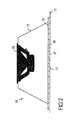
- Figure 1 is a schematic diagram of a first exemplary loudspeaker assembly.
- Figure 2 is a schematic diagram of a loudspeaker carrier secured to vehicle bodywork.
- Figure 3 is a schematic diagram of a second exemplary loudspeaker assembly.
- Figure 4 is a schematic diagram of a third exemplary loudspeaker assembly.
- Figure 5 is a schematic diagram of a fourth exemplary loudspeaker assembly.
- Figure 1 illustrates a first exemplary loudspeaker assembly 10 including a loudspeaker carrier 11, a mounting site 12 on a portion of a vehicle bodywork 13 and a layer 14 of expandable material which is positioned on a surface 15 of the loudspeaker carrier 11 which is to be mounted on the mounting site 12 of the vehicle bodywork 13.
- the loudspeaker carrier 11 is a loudspeaker enclosure.
- loudspeaker carrier is used to denote any structure supporting directly or indirectly a loudspeaker diaphragm 16.
- the loudspeaker diaphragm 16 faces away from the mounting site 12.
- the expandable material 14 has a composition such that it may be activated to cause the material to expand and, in particular, to form a foam structure with an increased volume. Upon activation, the expandable material 14 increases in volume to extend between the mounting surface 15 of the loudspeaker carrier 11 and the mounting site 12. Additionally, upon activation, the expandable material 14 becomes tacky and acts as an adhesive so that the expanded material with the foam structure also provides an adhesive joint between the loudspeaker carrier 11 and the mounting site 12 so as to secure the loudspeaker carrier 11 to the vehicle bodywork 13.
- the expandable material may be rubber-based or thermoplastic based and may be activated by subjecting it to a temperature above a predetermined threshold value, for example.
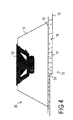
- Figure 2 illustrates the loudspeaker assembly 10 of the first exemplary embodiment after activation of the expandable material.
- the foam structure 17 is indicated schematically in figure 2 by the closed pores 18.
- the closed pores 18 are merely of an illustrative nature and are not intended to limit the structure of the expanded material to a foam structure with closed pores.
- the expanded material may also include a structure in which the foam includes interconnected cavities which extend from one side of the material to another.
- An exemplary expandable material 14 may include an ionomer, a temperature activated foaming agent capable of increasing the volume of the material when it is subjected to an elevated temperature, and a tackifier for imparting tackiness to at
- the ionomer may be an ethylene - ⁇ , ⁇ ethylenically unsaturated carboxylic acid, partially metallic ion neutralized copolymer ionomer.
- the relative proportions of the ionomer, temperature activated foaming agent and tackifier may be adjusted to provide the desired increase in volume, activation temperature and adhesion. Specific examples of compositions suitable for use as the expandable material are given in the examples disclosed in US 5,266,133 .
- the volume increase of the expandable material 14 maybe 100% to 1200%.
- the volume increase may be selected by selecting the proportion of the temperature activated foaming agent included in the expandable material 14.
- the expandable material 14 may be activated by subjecting the expandable material to an elevated temperature, for example 100°C to 250°C.
- the activation of the expandable material and the adhesion of the loudspeaker carrier 11 to the vehicle bodywork 13 is carried out during the so-called bake process or electrocoat bake process used in the priming and electrocoat process carried out on the vehicle bodywork.
- the entire vehicle chassis is subjected to a bake process, for example at 180°C, to dry and cross-link the anticorrosion coatings, primer and paintwork applied to the chassis or vehicle bodywork.
- the loudspeaker carrier 11 is arranged on the mounting site 12 in the manufacturing line before the electrocoat bake process and subjected to the electrocoat bake process along with the vehicle bodywork. This exemplary method avoids the need for a further process to secure the loudspeaker carrier 11 to the vehicle bodywork 13.
- the expanded material having the foam structure 17 may also be used to seal the loudspeaker carrier 11 to the vehicle bodywork 13 and may also act as an acoustic baffle to improve the perceived sound quality of the loudspeaker. Since mechanical fixings such as screws and clips are no longer required to secure the loudspeaker carrier 11 to the vehicle bodywork 13, any unwanted sources of noise such as rattles, which may occur at these mechanical fixings, can be avoided.
- a further adhesive layer may be used to attach the expandable material 14 to the loudspeaker carrier 11 and the mounting site 12 of the vehicle bodywork 13.
- the mounting site 12 is planar and continuous.
- the expandable material 14 is used to mount a loudspeaker carrier 11 on nonplanar surfaces.
- Like features are indicated with like reference numbers.
- FIG. 3 illustrates a second exemplary loudspeaker assembly 20 which includes a loudspeaker carrier 11 which is to be mounted by a layer of expandable material 14 to vehicle bodywork 13.
- the mounting site 12 of the vehicle bodywork includes two abutting portions 21, 22, each with a chamfered edge 23 which produces a cavity 24 in the vehicle bodywork 13 at the mounting site 12 between the two abutting portions 21, 22.
- the cavity 24 is filled, at least in part, by the increased volume of the expanded material which now has a foam structure.
- Figure 4 illustrates a third exemplary loudspeaker assembly 30 in which the loudspeaker carrier 11 is mounted on a mounting site 12 which has a step 31.
- Figure 4 illustrates the loudspeaker assembly 10 after activation of the expandable material so that the loudspeaker carrier 11 is mounted via a foam material 17 to the mounting site 12 of the vehicle bodywork 13.
- the increase in volume of the expandable material achieved by thermal activation can be used to compensate for the step structure of the mounting site 12.
- the foam material 17 extends between the mounting surface 15 of the loudspeaker carrier 11 and the mounting site 12 of the vehicle bodywork 13.
- the foam material is also adhesive and secures the loudspeaker carrier 11 to the vehicle bodywork 13 in addition to providing a seal around the loudspeaker carrier 11.
- FIG. 5 illustrates a fourth exemplary loudspeaker assembly 40 in which the loudspeaker carrier 11 is mounted on a mounting site 12 of the vehicle bodywork 13 by a layer of foamed material 17 which extends between the mounting surface 15 of the loudspeaker carrier 11 and the mounting site 12.
- the mounting site 12 includes a welded overlapping joint 41 between two portions 42, 43 of the mounting site 12 which produces a step 44 in the mounting site 12 at the welded seam 45 between the two overlapping portions 42, 43.
- the foam material 17 is produced by activation of an expandable material.
- the expandable material is also tacky so that the expanded foam material secures the loudspeaker carrier 11 to the vehicle bodywork 13. Due to the expansion of the expandable material, the step 44 and increased gap between the mounting surface 15 of the loudspeaker carrier 11 and mounting site 12 may be filled so that the foam material 17 extends between mounting surface 15 and the mounting site 12 of the vehicle bodywork 13.
- the loudspeaker carrier 11 is planar despite the step 44 in the mounting site 12.
- the expandable material 14 may be applied to the loudspeaker carrier 11 or to the mounting site 12 of the vehicle bodywork 13.
- the expandable material 14 may be attached to the loudspeaker carrier 11 by co-molding the expandable material with the loudspeaker carrier 11, for example.
- the expandable material 14 may be attached by a further adhesive layer or by a mechanical fixing arrangement, for example by lugs or protrusions which protrude from either the loudspeaker carrier or the mounting site.
- a temperature activated expandable material and, for example, a temperature activated foamable material which also has an adhesive function enables the attachment and sealing of the loudspeaker carrier 11 to the vehicle bodywork 13 in a single step which can be carried out at the same time as the baking of the anticorrosion coating, primer and or paint of the vehicle bodywork.
- a typical baking process may be carried out at 160° for around 20 min, for example.
- the loudspeaker carrier 11 need not be attached to the vehicle bodywork 13 by additional mechanical fixings such as screws, there are fewer restraints on the mechanical stability of the loudspeaker carrier itself.
- the sue of an expanded layer to provide both adhesion, sealing and acoustic baffling for the loudspeaker carrier may enable the width of the seal and/or the space required for the package as a whole to be reduced.
- the properties of the mounting site for example roughness and cleanliness, required to achieve a reliable adhesive joint and seal may be less stringent.
- the expandable material may be used to compensate for variations in bodywork tournaments since the material can expand to fill any cavities, roughness, flange steps, small radii and tangential assembled bodywork.
Landscapes
- Chemical & Material Sciences (AREA)
- Engineering & Computer Science (AREA)
- Organic Chemistry (AREA)
- Electrochemistry (AREA)
- Materials Engineering (AREA)
- Metallurgy (AREA)
- Chemical Kinetics & Catalysis (AREA)
- Physics & Mathematics (AREA)
- Acoustics & Sound (AREA)
- Signal Processing (AREA)
- Mechanical Engineering (AREA)
- Details Of Audible-Bandwidth Transducers (AREA)
- Diaphragms For Electromechanical Transducers (AREA)
- Fittings On The Vehicle Exterior For Carrying Loads, And Devices For Holding Or Mounting Articles (AREA)
Abstract
Description
- The disclosure relates to a loudspeaker carrier, a loudspeaker assembly and a method for mounting a loudspeaker carrier in a vehicle.
- Vehicles such as automobiles may include an infotainment system with one or more loudspeakers. The loudspeakers may be mounted at various sites within the vehicle, for example in the dashboard, in the door panels and/or underneath the seats, depending on the available space and number and type of loudspeakers of the infotainment system.
- Commonly a loudspeaker is mounted in a cavity formed within the vehicle bodywork. The cavity may be fabricated by inserting a deformable plastic precursor in an opening in the vehicle bodywork and expanding the plastic precursor to form the cavity. The loudspeaker module may be screwed into the structure so that the diaphragm of the loudspeaker is positioned above the opening to the cavity.
- Further arrangements and methods for mounting a loudspeaker in a vehicle which are simple to perform are, however, desirable.
- A loudspeaker carrier is provided that comprises a layer of expandable material arranged on a surface to be mounted to a mounting site of a vehicle bodywork.
- A loudspeaker assembly is provided that comprises a loudspeaker carrier, a mounting site on a vehicle bodywork and a layer of expandable material arranged between the loudspeaker carrier and the mounting site.
- A loudspeaker assembly is provided that comprises a loudspeaker carrier, a mounting site on a vehicle bodywork, and foamed material arranged between the loudspeaker carrier and the mounting site and securing the loudspeaker carrier to the mounting site.
- A method for mounting a loudspeaker carrier in a vehicle is provided that comprises providing a loudspeaker carrier, providing an expandable material, arranging the expandable material between the loudspeaker carrier and a mounting site on bodywork of the vehicle and activating the expandable material such that the material expands, forming a foam structure and causes the loudspeaker carrier to be secured to the bodywork.
- Other systems, methods, features and advantages will be, or will become, apparent to one with skill in the art upon examination of the following figures and detailed description. It is intended that all such additional systems, methods, features and advantages be included within this description, be within the scope of the invention, and be protected by the following claims.
- The system may be better understood with reference to the following drawings and description. The components in the figures are not necessarily to scale, emphasis instead being placed upon illustrating the principles of the invention. Moreover, in the figures, like referenced numerals designate corresponding parts throughout the different views.
-
Figure 1 is a schematic diagram of a first exemplary loudspeaker assembly. -
Figure 2 is a schematic diagram of a loudspeaker carrier secured to vehicle bodywork. -
Figure 3 is a schematic diagram of a second exemplary loudspeaker assembly. -
Figure 4 is a schematic diagram of a third exemplary loudspeaker assembly. -
Figure 5 is a schematic diagram of a fourth exemplary loudspeaker assembly. -
Figure 1 illustrates a firstexemplary loudspeaker assembly 10 including aloudspeaker carrier 11, amounting site 12 on a portion of avehicle bodywork 13 and alayer 14 of expandable material which is positioned on asurface 15 of theloudspeaker carrier 11 which is to be mounted on themounting site 12 of thevehicle bodywork 13. - In this example, the
loudspeaker carrier 11 is a loudspeaker enclosure. However, the term loudspeaker carrier is used to denote any structure supporting directly or indirectly aloudspeaker diaphragm 16. In this particular example, theloudspeaker diaphragm 16 faces away from themounting site 12. - The
expandable material 14 has a composition such that it may be activated to cause the material to expand and, in particular, to form a foam structure with an increased volume. Upon activation, theexpandable material 14 increases in volume to extend between the mountingsurface 15 of theloudspeaker carrier 11 and the mountingsite 12. Additionally, upon activation, theexpandable material 14 becomes tacky and acts as an adhesive so that the expanded material with the foam structure also provides an adhesive joint between theloudspeaker carrier 11 and the mountingsite 12 so as to secure theloudspeaker carrier 11 to thevehicle bodywork 13. The expandable material may be rubber-based or thermoplastic based and may be activated by subjecting it to a temperature above a predetermined threshold value, for example. -
Figure 2 illustrates theloudspeaker assembly 10 of the first exemplary embodiment after activation of the expandable material. Thefoam structure 17 is indicated schematically infigure 2 by the closed pores 18. However, theclosed pores 18 are merely of an illustrative nature and are not intended to limit the structure of the expanded material to a foam structure with closed pores. The expanded material may also include a structure in which the foam includes interconnected cavities which extend from one side of the material to another. - An exemplary
expandable material 14 may include an ionomer, a temperature activated foaming agent capable of increasing the volume of the material when it is subjected to an elevated temperature, and a tackifier for imparting tackiness to at - least the outer surface of the expandable material when it is subjected to the elevated temperature. The ionomer may be an ethylene - α, β ethylenically unsaturated carboxylic acid, partially metallic ion neutralized copolymer ionomer. The relative proportions of the ionomer, temperature activated foaming agent and tackifier may be adjusted to provide the desired increase in volume, activation temperature and adhesion. Specific examples of compositions suitable for use as the expandable material are given in the examples disclosed in
US 5,266,133 . - The volume increase of the
expandable material 14 maybe 100% to 1200%. The volume increase may be selected by selecting the proportion of the temperature activated foaming agent included in theexpandable material 14. Theexpandable material 14 may be activated by subjecting the expandable material to an elevated temperature, for example 100°C to 250°C. - In an exemplary method, the activation of the expandable material and the adhesion of the
loudspeaker carrier 11 to thevehicle bodywork 13 is carried out during the so-called bake process or electrocoat bake process used in the priming and electrocoat process carried out on the vehicle bodywork. In the electrocoat process, the entire vehicle chassis is subjected to a bake process, for example at 180°C, to dry and cross-link the anticorrosion coatings, primer and paintwork applied to the chassis or vehicle bodywork. Theloudspeaker carrier 11 is arranged on the mountingsite 12 in the manufacturing line before the electrocoat bake process and subjected to the electrocoat bake process along with the vehicle bodywork. This exemplary method avoids the need for a further process to secure theloudspeaker carrier 11 to thevehicle bodywork 13. - The expanded material having the
foam structure 17 may also be used to seal theloudspeaker carrier 11 to thevehicle bodywork 13 and may also act as an acoustic baffle to improve the perceived sound quality of the loudspeaker. Since mechanical fixings such as screws and clips are no longer required to secure theloudspeaker carrier 11 to thevehicle bodywork 13, any unwanted sources of noise such as rattles, which may occur at these mechanical fixings, can be avoided. - In examples in which the expandable material is not itself adhesive at the activation temperature, a further adhesive layer may be used to attach the
expandable material 14 to theloudspeaker carrier 11 and the mountingsite 12 of thevehicle bodywork 13. - In the first
exemplary loudspeaker assembly 10 illustrated infigures 1 and2 , the mountingsite 12 is planar and continuous. In the following exemplary loudspeaker assemblies, theexpandable material 14 is used to mount aloudspeaker carrier 11 on nonplanar surfaces. Like features are indicated with like reference numbers. -
Figure 3 illustrates a secondexemplary loudspeaker assembly 20 which includes aloudspeaker carrier 11 which is to be mounted by a layer ofexpandable material 14 tovehicle bodywork 13. In the secondexemplary loudspeaker assembly 20, the mountingsite 12 of the vehicle bodywork includes two abuttingportions edge 23 which produces acavity 24 in thevehicle bodywork 13 at the mountingsite 12 between the two abuttingportions expandable material 14, thecavity 24 is filled, at least in part, by the increased volume of the expanded material which now has a foam structure. -
Figure 4 illustrates a thirdexemplary loudspeaker assembly 30 in which theloudspeaker carrier 11 is mounted on a mountingsite 12 which has astep 31.Figure 4 illustrates theloudspeaker assembly 10 after activation of the expandable material so that theloudspeaker carrier 11 is mounted via afoam material 17 to the mountingsite 12 of thevehicle bodywork 13. The increase in volume of the expandable material achieved by thermal activation can be used to compensate for the step structure of the mountingsite 12. Thefoam material 17 extends between themounting surface 15 of theloudspeaker carrier 11 and themounting site 12 of thevehicle bodywork 13. The foam material is also adhesive and secures theloudspeaker carrier 11 to thevehicle bodywork 13 in addition to providing a seal around theloudspeaker carrier 11. -
Figure 5 illustrates a fourthexemplary loudspeaker assembly 40 in which theloudspeaker carrier 11 is mounted on a mountingsite 12 of thevehicle bodywork 13 by a layer of foamedmaterial 17 which extends between the mountingsurface 15 of theloudspeaker carrier 11 and the mountingsite 12. The mountingsite 12 includes a welded overlapping joint 41 between twoportions site 12 which produces astep 44 in the mountingsite 12 at the weldedseam 45 between the two overlappingportions - The
foam material 17 is produced by activation of an expandable material. Upon activation, the expandable material is also tacky so that the expanded foam material secures theloudspeaker carrier 11 to thevehicle bodywork 13. Due to the expansion of the expandable material, thestep 44 and increased gap between the mountingsurface 15 of theloudspeaker carrier 11 and mountingsite 12 may be filled so that thefoam material 17 extends between mountingsurface 15 and the mountingsite 12 of thevehicle bodywork 13. Theloudspeaker carrier 11 is planar despite thestep 44 in the mountingsite 12. - The
expandable material 14 may be applied to theloudspeaker carrier 11 or to the mountingsite 12 of thevehicle bodywork 13. Theexpandable material 14 may be attached to theloudspeaker carrier 11 by co-molding the expandable material with theloudspeaker carrier 11, for example. Theexpandable material 14 may be attached by a further adhesive layer or by a mechanical fixing arrangement, for example by lugs or protrusions which protrude from either the loudspeaker carrier or the mounting site. - The use of a temperature activated expandable material and, for example, a temperature activated foamable material which also has an adhesive function enables the attachment and sealing of the
loudspeaker carrier 11 to thevehicle bodywork 13 in a single step which can be carried out at the same time as the baking of the anticorrosion coating, primer and or paint of the vehicle bodywork. A typical baking process may be carried out at 160° for around 20 min, for example. - Since the
loudspeaker carrier 11 need not be attached to thevehicle bodywork 13 by additional mechanical fixings such as screws, there are fewer restraints on the mechanical stability of the loudspeaker carrier itself. The sue of an expanded layer to provide both adhesion, sealing and acoustic baffling for the loudspeaker carrier may enable the width of the seal and/or the space required for the package as a whole to be reduced. Depending on the composition of the expandable material, the properties of the mounting site, for example roughness and cleanliness, required to achieve a reliable adhesive joint and seal may be less stringent. The expandable material may be used to compensate for variations in bodywork tournaments since the material can expand to fill any cavities, roughness, flange steps, small radii and tangential assembled bodywork. - While various embodiments of the invention have been described, it will be apparent to those of ordinary skill in the art that many more embodiments and implementations are possible within the scope of the invention. Accordingly, the invention is not to be restricted except in light of the attached claims and their equivalents.
Claims (15)
- A method for mounting a loudspeaker carrier in a vehicle, comprising:providing a loudspeaker carrier;providing an expandable material;arranging the expandable material between the loudspeaker carrier and a mounting site on bodywork of the vehicle;activating the expandable material such that the material expands, forming a foam structure and causes the loudspeaker to be secured to the bodywork.
- The method according to claim 1, wherein the expandable material is activated by applying an elevated temperature.
- The method according to claim 2, wherein the elevated temperature is 100°C to 250°C.
- The method according to any one of claims 1 to 3, further comprising activating the expandable material by subjecting the loudspeaker carrier, expandable material and vehicle bodywork to an electrocoat bake process.
- The method according to any one of claims 1 to 4, where during the activating, at least outer surfaces of the expandable material become tacky and adhere the loudspeaker enclosure to the bodywork.
- The method according to any one of claims 1 to 5, where during the activating, the volume of the expandable material increases from 100% to 1200%.
- The method according to any one of claims 1 to 6, further comprising attaching the expandable material to the loudspeaker carrier by co-molding, by an adhesive layer, or by a mechanical fixing.
- A loudspeaker carrier, comprising a layer of expandable material arranged on a surface to be mounted on a mounting site of a vehicle bodywork.
- The loudspeaker carrier according to claim 8, where the expandable material is co-molded to the loudspeaker carrier, or is attached to the loudspeaker carrier by an adhesive layer or by a mechanical fixing.
- A loudspeaker assembly, comprising a loudspeaker carrier, a mounting site on a vehicle bodywork and a layer of expandable material arranged between the loudspeaker carrier and the mounting site.
- The loudspeaker assembly according to claim 10, where the mounting site comprises at least one of an abutment, a welded seam and a step, or is planar.
- The loudspeaker assembly according to claim 10 or claim 11, where the expandable material comprises:an ionomer;a temperature activated foaming agent capable of increasing the volume of the material when it is subjected to an elevated temperature, anda tackifier for imparting tackiness to at least the outer surface of the expandable material when it is subjected to said elevated temperature.
- The loudspeaker assembly according to claim 12, where the ionomer is an ethylene - α, β ethylenically unsaturated carboxylic acid, partially metallic ion neutralized copolymer ionomer.
- A loudspeaker assembly, comprising a loudspeaker carrier, a mounting site on a vehicle bodywork, and foamed material arranged between the loudspeaker carrier and the mounting site and securing the loudspeaker carrier to the mounting site.
- The loudspeaker assembly according to claim 14, where the foamed material further provides a seal between the loudspeaker carrier and the vehicle body work.
Priority Applications (3)
| Application Number | Priority Date | Filing Date | Title |
|---|---|---|---|
| EP13168304.7A EP2804394B1 (en) | 2013-05-17 | 2013-05-17 | Method for mounting a loudspeaker carrier in a vehicle and corresponding loudspeaker assembly |
| CN201410102895.XA CN104168521B (en) | 2013-05-17 | 2014-03-19 | Loudspeaker carrier, method for mounting loudspeaker carrier in vehicle and loudspeaker assembly |
| US14/280,570 US9807486B2 (en) | 2013-05-17 | 2014-05-17 | Loudspeaker assembly in a vehicle using expandable material |
Applications Claiming Priority (1)
| Application Number | Priority Date | Filing Date | Title |
|---|---|---|---|
| EP13168304.7A EP2804394B1 (en) | 2013-05-17 | 2013-05-17 | Method for mounting a loudspeaker carrier in a vehicle and corresponding loudspeaker assembly |
Publications (2)
| Publication Number | Publication Date |
|---|---|
| EP2804394A1 true EP2804394A1 (en) | 2014-11-19 |
| EP2804394B1 EP2804394B1 (en) | 2018-08-08 |
Family
ID=48430589
Family Applications (1)
| Application Number | Title | Priority Date | Filing Date |
|---|---|---|---|
| EP13168304.7A Active EP2804394B1 (en) | 2013-05-17 | 2013-05-17 | Method for mounting a loudspeaker carrier in a vehicle and corresponding loudspeaker assembly |
Country Status (3)
| Country | Link |
|---|---|
| US (1) | US9807486B2 (en) |
| EP (1) | EP2804394B1 (en) |
| CN (1) | CN104168521B (en) |
Cited By (2)
| Publication number | Priority date | Publication date | Assignee | Title |
|---|---|---|---|---|
| WO2017021068A1 (en) * | 2015-07-31 | 2017-02-09 | Epcos Ag | Top port microphone and method for the production of same |
| WO2020249516A1 (en) * | 2019-06-13 | 2020-12-17 | Volkswagen Aktiengesellschaft | Damping device and loudspeaker damping system for a motor vehicle |
Families Citing this family (4)
| Publication number | Priority date | Publication date | Assignee | Title |
|---|---|---|---|---|
| US9845059B2 (en) | 2015-05-11 | 2017-12-19 | Bose Corporation | Acoustic enclosure for motor vehicle |
| JP6561210B2 (en) * | 2016-05-25 | 2019-08-14 | 株式会社タチエス | Headrest and vehicle seat |
| CN110271495A (en) * | 2018-03-13 | 2019-09-24 | 标致雪铁龙汽车股份有限公司 | Chamber mount and vehicle for vehicle speakers unit |
| US10848861B2 (en) | 2019-04-16 | 2020-11-24 | Harman Becker Automotive Systems Gmbh | Loudspeaker assembly for a vehicle |
Citations (3)
| Publication number | Priority date | Publication date | Assignee | Title |
|---|---|---|---|---|
| GB2106801A (en) * | 1981-09-30 | 1983-04-20 | Hermetite Products Limited | Resilient foam products |
| US5266133A (en) | 1993-02-17 | 1993-11-30 | Sika Corporation | Dry expansible sealant and baffle composition and product |
| WO2013011699A1 (en) * | 2011-07-21 | 2013-01-24 | 株式会社シーエンジ | Self-resonating sound emitting speaker and method for installing self-resonating sound emitting speaker |
Family Cites Families (8)
| Publication number | Priority date | Publication date | Assignee | Title |
|---|---|---|---|---|
| US4598178A (en) * | 1983-12-16 | 1986-07-01 | Rollins William L | Means for critically damping a dynamic loudspeaker |
| US5040803A (en) * | 1990-04-23 | 1991-08-20 | Cieslik David R | Cavity sealing arrangement and method |
| JP4170024B2 (en) * | 2002-06-07 | 2008-10-22 | 富士通テン株式会社 | In-vehicle speaker and its mounting structure |
| JP2004208067A (en) * | 2002-12-25 | 2004-07-22 | Mitsubishi Automob Eng Co Ltd | Vehicle speaker box structure |
| US7841647B2 (en) * | 2006-11-15 | 2010-11-30 | Sika Technology Ag | Baffle assembly |
| US8675907B2 (en) * | 2010-07-30 | 2014-03-18 | GM Global Technology Operations LLC | Vehicle audio system having door mounted speaker support |
| GB2490707B (en) * | 2011-05-11 | 2013-12-18 | Land Rover Uk Ltd | Assembly and method of manufacture thereof |
| CN102991434B (en) * | 2012-12-18 | 2016-05-18 | 奇瑞汽车股份有限公司 | A kind of expansion slab rubber and preparation thereof, installation method |
-
2013
- 2013-05-17 EP EP13168304.7A patent/EP2804394B1/en active Active
-
2014
- 2014-03-19 CN CN201410102895.XA patent/CN104168521B/en active Active
- 2014-05-17 US US14/280,570 patent/US9807486B2/en active Active
Patent Citations (4)
| Publication number | Priority date | Publication date | Assignee | Title |
|---|---|---|---|---|
| GB2106801A (en) * | 1981-09-30 | 1983-04-20 | Hermetite Products Limited | Resilient foam products |
| US5266133A (en) | 1993-02-17 | 1993-11-30 | Sika Corporation | Dry expansible sealant and baffle composition and product |
| WO2013011699A1 (en) * | 2011-07-21 | 2013-01-24 | 株式会社シーエンジ | Self-resonating sound emitting speaker and method for installing self-resonating sound emitting speaker |
| US20130228392A1 (en) * | 2011-07-21 | 2013-09-05 | C-Eng Co., Ltd. | Self resonance-type sound-producing speaker and method of placing thereof |
Cited By (4)
| Publication number | Priority date | Publication date | Assignee | Title |
|---|---|---|---|---|
| WO2017021068A1 (en) * | 2015-07-31 | 2017-02-09 | Epcos Ag | Top port microphone and method for the production of same |
| CN107925809A (en) * | 2015-07-31 | 2018-04-17 | Tdk株式会社 | The microphone of advance sound formula and the method for manufacture |
| US10194227B2 (en) | 2015-07-31 | 2019-01-29 | Tdk Corporation | Top port microphone and method for the production of same |
| WO2020249516A1 (en) * | 2019-06-13 | 2020-12-17 | Volkswagen Aktiengesellschaft | Damping device and loudspeaker damping system for a motor vehicle |
Also Published As
| Publication number | Publication date |
|---|---|
| CN104168521B (en) | 2020-02-28 |
| EP2804394B1 (en) | 2018-08-08 |
| US9807486B2 (en) | 2017-10-31 |
| US20140341391A1 (en) | 2014-11-20 |
| CN104168521A (en) | 2014-11-26 |
Similar Documents
| Publication | Publication Date | Title |
|---|---|---|
| US9807486B2 (en) | Loudspeaker assembly in a vehicle using expandable material | |
| US8215704B2 (en) | Acoustic baffle | |
| US7494179B2 (en) | Member for baffling, reinforcement or sealing | |
| EP1731284B1 (en) | Noise reduction member and system | |
| US20230015873A1 (en) | Laminate including aluminum sheets | |
| KR101487149B1 (en) | Acoustic baffle | |
| KR20100014646A (en) | Sound-absorbing baffle for sealing a hollow space | |
| US8434826B2 (en) | Structure for a vehicle seat | |
| JP2004131062A (en) | Attachment system and its manufacturing method | |
| KR20080034493A (en) | Reinforcements, baffles and seals with malleable carriers | |
| EP1717480A2 (en) | Dampener | |
| WO2015179383A1 (en) | Method and device for reinforcement | |
| WO2009049886A1 (en) | Multifunctional vehicle components | |
| US20070259171A1 (en) | Repair laminate for mounting brackets and method of using the same | |
| US20050251988A1 (en) | Hole plugs | |
| WO2015012937A1 (en) | Expanadable hole plug assembly | |
| US20180304822A1 (en) | Trim part with integrated antenna | |
| JP2012518767A (en) | Damping device for flat components | |
| CN106882125A (en) | The mounting structure of a kind of moulding and vehicle body counterpart, moulding and vehicle | |
| US10384419B2 (en) | Baffle | |
| JP4302866B2 (en) | Air-conditioning duct integrated instrument panel structure and manufacturing method thereof | |
| WO2003093064A1 (en) | Vehicle body cavity filler | |
| US8523272B1 (en) | Panel assembly for a vehicle and a method of supporting the panel assembly | |
| KR20090005129A (en) | Repair laminate for mounting brackets and method of using the same | |
| US20070200047A1 (en) | Expandable reinforcing member |
Legal Events
| Date | Code | Title | Description |
|---|---|---|---|
| PUAI | Public reference made under article 153(3) epc to a published international application that has entered the european phase |
Free format text: ORIGINAL CODE: 0009012 |
|
| 17P | Request for examination filed |
Effective date: 20130517 |
|
| AK | Designated contracting states |
Kind code of ref document: A1 Designated state(s): AL AT BE BG CH CY CZ DE DK EE ES FI FR GB GR HR HU IE IS IT LI LT LU LV MC MK MT NL NO PL PT RO RS SE SI SK SM TR |
|
| AX | Request for extension of the european patent |
Extension state: BA ME |
|
| R17P | Request for examination filed (corrected) |
Effective date: 20150512 |
|
| RBV | Designated contracting states (corrected) |
Designated state(s): AL AT BE BG CH CY CZ DE DK EE ES FI FR GB GR HR HU IE IS IT LI LT LU LV MC MK MT NL NO PL PT RO RS SE SI SK SM TR |
|
| RIC1 | Information provided on ipc code assigned before grant |
Ipc: B60R 11/02 20060101ALI20180202BHEP Ipc: H04R 1/02 20060101AFI20180202BHEP Ipc: C25D 13/12 20060101ALI20180202BHEP Ipc: C25D 13/20 20060101ALI20180202BHEP Ipc: C09J 5/08 20060101ALI20180202BHEP |
|
| GRAP | Despatch of communication of intention to grant a patent |
Free format text: ORIGINAL CODE: EPIDOSNIGR1 |
|
| STAA | Information on the status of an ep patent application or granted ep patent |
Free format text: STATUS: GRANT OF PATENT IS INTENDED |
|
| INTG | Intention to grant announced |
Effective date: 20180524 |
|
| GRAS | Grant fee paid |
Free format text: ORIGINAL CODE: EPIDOSNIGR3 |
|
| GRAA | (expected) grant |
Free format text: ORIGINAL CODE: 0009210 |
|
| STAA | Information on the status of an ep patent application or granted ep patent |
Free format text: STATUS: THE PATENT HAS BEEN GRANTED |
|
| AK | Designated contracting states |
Kind code of ref document: B1 Designated state(s): AL AT BE BG CH CY CZ DE DK EE ES FI FR GB GR HR HU IE IS IT LI LT LU LV MC MK MT NL NO PL PT RO RS SE SI SK SM TR |
|
| REG | Reference to a national code |
Ref country code: GB Ref legal event code: FG4D |
|
| REG | Reference to a national code |
Ref country code: CH Ref legal event code: EP Ref country code: AT Ref legal event code: REF Ref document number: 1028439 Country of ref document: AT Kind code of ref document: T Effective date: 20180815 |
|
| REG | Reference to a national code |
Ref country code: IE Ref legal event code: FG4D |
|
| REG | Reference to a national code |
Ref country code: DE Ref legal event code: R096 Ref document number: 602013041480 Country of ref document: DE |
|
| REG | Reference to a national code |
Ref country code: NL Ref legal event code: MP Effective date: 20180808 |
|
| REG | Reference to a national code |
Ref country code: LT Ref legal event code: MG4D |
|
| REG | Reference to a national code |
Ref country code: AT Ref legal event code: MK05 Ref document number: 1028439 Country of ref document: AT Kind code of ref document: T Effective date: 20180808 |
|
| PG25 | Lapsed in a contracting state [announced via postgrant information from national office to epo] |
Ref country code: NO Free format text: LAPSE BECAUSE OF FAILURE TO SUBMIT A TRANSLATION OF THE DESCRIPTION OR TO PAY THE FEE WITHIN THE PRESCRIBED TIME-LIMIT Effective date: 20181108 Ref country code: AT Free format text: LAPSE BECAUSE OF FAILURE TO SUBMIT A TRANSLATION OF THE DESCRIPTION OR TO PAY THE FEE WITHIN THE PRESCRIBED TIME-LIMIT Effective date: 20180808 Ref country code: IS Free format text: LAPSE BECAUSE OF FAILURE TO SUBMIT A TRANSLATION OF THE DESCRIPTION OR TO PAY THE FEE WITHIN THE PRESCRIBED TIME-LIMIT Effective date: 20181208 Ref country code: RS Free format text: LAPSE BECAUSE OF FAILURE TO SUBMIT A TRANSLATION OF THE DESCRIPTION OR TO PAY THE FEE WITHIN THE PRESCRIBED TIME-LIMIT Effective date: 20180808 Ref country code: SE Free format text: LAPSE BECAUSE OF FAILURE TO SUBMIT A TRANSLATION OF THE DESCRIPTION OR TO PAY THE FEE WITHIN THE PRESCRIBED TIME-LIMIT Effective date: 20180808 Ref country code: GR Free format text: LAPSE BECAUSE OF FAILURE TO SUBMIT A TRANSLATION OF THE DESCRIPTION OR TO PAY THE FEE WITHIN THE PRESCRIBED TIME-LIMIT Effective date: 20181109 Ref country code: FI Free format text: LAPSE BECAUSE OF FAILURE TO SUBMIT A TRANSLATION OF THE DESCRIPTION OR TO PAY THE FEE WITHIN THE PRESCRIBED TIME-LIMIT Effective date: 20180808 Ref country code: PL Free format text: LAPSE BECAUSE OF FAILURE TO SUBMIT A TRANSLATION OF THE DESCRIPTION OR TO PAY THE FEE WITHIN THE PRESCRIBED TIME-LIMIT Effective date: 20180808 Ref country code: NL Free format text: LAPSE BECAUSE OF FAILURE TO SUBMIT A TRANSLATION OF THE DESCRIPTION OR TO PAY THE FEE WITHIN THE PRESCRIBED TIME-LIMIT Effective date: 20180808 Ref country code: BG Free format text: LAPSE BECAUSE OF FAILURE TO SUBMIT A TRANSLATION OF THE DESCRIPTION OR TO PAY THE FEE WITHIN THE PRESCRIBED TIME-LIMIT Effective date: 20181108 Ref country code: LT Free format text: LAPSE BECAUSE OF FAILURE TO SUBMIT A TRANSLATION OF THE DESCRIPTION OR TO PAY THE FEE WITHIN THE PRESCRIBED TIME-LIMIT Effective date: 20180808 |
|
| PG25 | Lapsed in a contracting state [announced via postgrant information from national office to epo] |
Ref country code: AL Free format text: LAPSE BECAUSE OF FAILURE TO SUBMIT A TRANSLATION OF THE DESCRIPTION OR TO PAY THE FEE WITHIN THE PRESCRIBED TIME-LIMIT Effective date: 20180808 Ref country code: HR Free format text: LAPSE BECAUSE OF FAILURE TO SUBMIT A TRANSLATION OF THE DESCRIPTION OR TO PAY THE FEE WITHIN THE PRESCRIBED TIME-LIMIT Effective date: 20180808 Ref country code: LV Free format text: LAPSE BECAUSE OF FAILURE TO SUBMIT A TRANSLATION OF THE DESCRIPTION OR TO PAY THE FEE WITHIN THE PRESCRIBED TIME-LIMIT Effective date: 20180808 |
|
| PG25 | Lapsed in a contracting state [announced via postgrant information from national office to epo] |
Ref country code: EE Free format text: LAPSE BECAUSE OF FAILURE TO SUBMIT A TRANSLATION OF THE DESCRIPTION OR TO PAY THE FEE WITHIN THE PRESCRIBED TIME-LIMIT Effective date: 20180808 Ref country code: RO Free format text: LAPSE BECAUSE OF FAILURE TO SUBMIT A TRANSLATION OF THE DESCRIPTION OR TO PAY THE FEE WITHIN THE PRESCRIBED TIME-LIMIT Effective date: 20180808 Ref country code: CZ Free format text: LAPSE BECAUSE OF FAILURE TO SUBMIT A TRANSLATION OF THE DESCRIPTION OR TO PAY THE FEE WITHIN THE PRESCRIBED TIME-LIMIT Effective date: 20180808 Ref country code: ES Free format text: LAPSE BECAUSE OF FAILURE TO SUBMIT A TRANSLATION OF THE DESCRIPTION OR TO PAY THE FEE WITHIN THE PRESCRIBED TIME-LIMIT Effective date: 20180808 Ref country code: IT Free format text: LAPSE BECAUSE OF FAILURE TO SUBMIT A TRANSLATION OF THE DESCRIPTION OR TO PAY THE FEE WITHIN THE PRESCRIBED TIME-LIMIT Effective date: 20180808 |
|
| REG | Reference to a national code |
Ref country code: DE Ref legal event code: R097 Ref document number: 602013041480 Country of ref document: DE |
|
| PG25 | Lapsed in a contracting state [announced via postgrant information from national office to epo] |
Ref country code: SK Free format text: LAPSE BECAUSE OF FAILURE TO SUBMIT A TRANSLATION OF THE DESCRIPTION OR TO PAY THE FEE WITHIN THE PRESCRIBED TIME-LIMIT Effective date: 20180808 Ref country code: SM Free format text: LAPSE BECAUSE OF FAILURE TO SUBMIT A TRANSLATION OF THE DESCRIPTION OR TO PAY THE FEE WITHIN THE PRESCRIBED TIME-LIMIT Effective date: 20180808 Ref country code: DK Free format text: LAPSE BECAUSE OF FAILURE TO SUBMIT A TRANSLATION OF THE DESCRIPTION OR TO PAY THE FEE WITHIN THE PRESCRIBED TIME-LIMIT Effective date: 20180808 |
|
| PLBE | No opposition filed within time limit |
Free format text: ORIGINAL CODE: 0009261 |
|
| STAA | Information on the status of an ep patent application or granted ep patent |
Free format text: STATUS: NO OPPOSITION FILED WITHIN TIME LIMIT |
|
| 26N | No opposition filed |
Effective date: 20190509 |
|
| PG25 | Lapsed in a contracting state [announced via postgrant information from national office to epo] |
Ref country code: SI Free format text: LAPSE BECAUSE OF FAILURE TO SUBMIT A TRANSLATION OF THE DESCRIPTION OR TO PAY THE FEE WITHIN THE PRESCRIBED TIME-LIMIT Effective date: 20180808 |
|
| REG | Reference to a national code |
Ref country code: CH Ref legal event code: PL |
|
| PG25 | Lapsed in a contracting state [announced via postgrant information from national office to epo] |
Ref country code: LI Free format text: LAPSE BECAUSE OF NON-PAYMENT OF DUE FEES Effective date: 20190531 Ref country code: MC Free format text: LAPSE BECAUSE OF FAILURE TO SUBMIT A TRANSLATION OF THE DESCRIPTION OR TO PAY THE FEE WITHIN THE PRESCRIBED TIME-LIMIT Effective date: 20180808 Ref country code: CH Free format text: LAPSE BECAUSE OF NON-PAYMENT OF DUE FEES Effective date: 20190531 |
|
| REG | Reference to a national code |
Ref country code: BE Ref legal event code: MM Effective date: 20190531 |
|
| PG25 | Lapsed in a contracting state [announced via postgrant information from national office to epo] |
Ref country code: LU Free format text: LAPSE BECAUSE OF NON-PAYMENT OF DUE FEES Effective date: 20190517 |
|
| PG25 | Lapsed in a contracting state [announced via postgrant information from national office to epo] |
Ref country code: TR Free format text: LAPSE BECAUSE OF FAILURE TO SUBMIT A TRANSLATION OF THE DESCRIPTION OR TO PAY THE FEE WITHIN THE PRESCRIBED TIME-LIMIT Effective date: 20180808 |
|
| PG25 | Lapsed in a contracting state [announced via postgrant information from national office to epo] |
Ref country code: IE Free format text: LAPSE BECAUSE OF NON-PAYMENT OF DUE FEES Effective date: 20190517 |
|
| PG25 | Lapsed in a contracting state [announced via postgrant information from national office to epo] |
Ref country code: BE Free format text: LAPSE BECAUSE OF NON-PAYMENT OF DUE FEES Effective date: 20190531 |
|
| PG25 | Lapsed in a contracting state [announced via postgrant information from national office to epo] |
Ref country code: FR Free format text: LAPSE BECAUSE OF NON-PAYMENT OF DUE FEES Effective date: 20190531 Ref country code: PT Free format text: LAPSE BECAUSE OF FAILURE TO SUBMIT A TRANSLATION OF THE DESCRIPTION OR TO PAY THE FEE WITHIN THE PRESCRIBED TIME-LIMIT Effective date: 20181208 |
|
| PG25 | Lapsed in a contracting state [announced via postgrant information from national office to epo] |
Ref country code: CY Free format text: LAPSE BECAUSE OF FAILURE TO SUBMIT A TRANSLATION OF THE DESCRIPTION OR TO PAY THE FEE WITHIN THE PRESCRIBED TIME-LIMIT Effective date: 20180808 |
|
| PG25 | Lapsed in a contracting state [announced via postgrant information from national office to epo] |
Ref country code: MT Free format text: LAPSE BECAUSE OF FAILURE TO SUBMIT A TRANSLATION OF THE DESCRIPTION OR TO PAY THE FEE WITHIN THE PRESCRIBED TIME-LIMIT Effective date: 20180808 Ref country code: HU Free format text: LAPSE BECAUSE OF FAILURE TO SUBMIT A TRANSLATION OF THE DESCRIPTION OR TO PAY THE FEE WITHIN THE PRESCRIBED TIME-LIMIT; INVALID AB INITIO Effective date: 20130517 |
|
| PG25 | Lapsed in a contracting state [announced via postgrant information from national office to epo] |
Ref country code: MK Free format text: LAPSE BECAUSE OF FAILURE TO SUBMIT A TRANSLATION OF THE DESCRIPTION OR TO PAY THE FEE WITHIN THE PRESCRIBED TIME-LIMIT Effective date: 20180808 |
|
| P01 | Opt-out of the competence of the unified patent court (upc) registered |
Effective date: 20230526 |
|
| PGFP | Annual fee paid to national office [announced via postgrant information from national office to epo] |
Ref country code: GB Payment date: 20240419 Year of fee payment: 12 |
|
| PGFP | Annual fee paid to national office [announced via postgrant information from national office to epo] |
Ref country code: DE Payment date: 20240418 Year of fee payment: 12 |