JP4170024B2 - In-vehicle speaker and its mounting structure - Google Patents
In-vehicle speaker and its mounting structure Download PDFInfo
- Publication number
- JP4170024B2 JP4170024B2 JP2002167799A JP2002167799A JP4170024B2 JP 4170024 B2 JP4170024 B2 JP 4170024B2 JP 2002167799 A JP2002167799 A JP 2002167799A JP 2002167799 A JP2002167799 A JP 2002167799A JP 4170024 B2 JP4170024 B2 JP 4170024B2
- Authority
- JP
- Japan
- Prior art keywords
- speaker
- vehicle
- sound
- sound output
- speaker box
- Prior art date
- Legal status (The legal status is an assumption and is not a legal conclusion. Google has not performed a legal analysis and makes no representation as to the accuracy of the status listed.)
- Expired - Fee Related
Links
Images

Classifications
-
- H—ELECTRICITY
- H04—ELECTRIC COMMUNICATION TECHNIQUE
- H04R—LOUDSPEAKERS, MICROPHONES, GRAMOPHONE PICK-UPS OR LIKE ACOUSTIC ELECTROMECHANICAL TRANSDUCERS; DEAF-AID SETS; PUBLIC ADDRESS SYSTEMS
- H04R1/00—Details of transducers, loudspeakers or microphones
- H04R1/02—Casings; Cabinets ; Supports therefor; Mountings therein
- H04R1/025—Arrangements for fixing loudspeaker transducers, e.g. in a box, furniture
-
- B—PERFORMING OPERATIONS; TRANSPORTING
- B60—VEHICLES IN GENERAL
- B60R—VEHICLES, VEHICLE FITTINGS, OR VEHICLE PARTS, NOT OTHERWISE PROVIDED FOR
- B60R11/00—Arrangements for holding or mounting articles, not otherwise provided for
- B60R11/02—Arrangements for holding or mounting articles, not otherwise provided for for radio sets, television sets, telephones, or the like; Arrangement of controls thereof
-
- H—ELECTRICITY
- H04—ELECTRIC COMMUNICATION TECHNIQUE
- H04R—LOUDSPEAKERS, MICROPHONES, GRAMOPHONE PICK-UPS OR LIKE ACOUSTIC ELECTROMECHANICAL TRANSDUCERS; DEAF-AID SETS; PUBLIC ADDRESS SYSTEMS
- H04R2499/00—Aspects covered by H04R or H04S not otherwise provided for in their subgroups
- H04R2499/10—General applications
- H04R2499/13—Acoustic transducers and sound field adaptation in vehicles
Description
【0001】
【発明の属する技術分野】
本発明は、車両に取付けて車室内に音響再生を行う車載用スピーカおよびその取付構造に関する。
【0002】
【従来の技術】
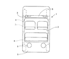
図4に示すように、従来から、乗用車などの車両1には、カーオーディオ用などとして車載用スピーカが搭載されている。一般的には、車両1の運転者などの車室2への搭乗者が、車両1の前方に向う姿勢で、左右2チャネルのステレオ再生を行うことが基本となるので、車載用スピーカ3,4,5は、インスツルメントパネル6、前後のドア7,8、またはトランクルーム9などの空間を利用して、左右に取付けられることが多い。特に、再生される音響出力を聴く搭乗者は、車両1の進行方向を向いた姿勢となるので、車両1では、車室2の前方のインスツルメントパネル6や側方のドア7,8などに車載用スピーカ3,4を配置することが多い。ただしこれらの部分で利用可能な空間はあまり大きくないので、低音域を再生する車載用スピーカ5を別に設ける場合は、車両1の後方のトランクルーム9の空間を利用し、その上方のリアトレイなどに開口するように配置することもある。音響出力の指向特性は、周波数が低いとあまり目立たなくなるので、低音域では左右を合成したモノラル再生でも、ステレオ感をあまり損うことはない。
【0003】
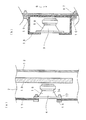
図5は、従来からの車載用スピーカの典型的な取付構造として、(a)で図4の車載用スピーカ4をドア7に取付ける構造を示し、(b)で図4の車載用スピーカ3をインスツルメントパネル6に取付ける構造を示す。図5(a)に示すように、ドア7には、スピーカユニット10を単体で取付け、ドア7で、内装材11と車体の最外方となる側板12との間に形成される空間をスピーカボックスとして利用することが多い。なお、この空間は、ドアのドアガラス13を引下げて開けるときに、ドアガラス13を収容するために設けられているので、スピーカユニット10を取付けても、ドアガラス13には当らないようにしなければならない。スピーカユニット10は、たとえばフレーム14の外周のフランジ15の部分を内装材11に設ける開口部の周辺にボルト16およびナット17で固定する。図5(b)に示すように、インスツルメントパネル6に取付けるスピーカ3は、スピーカユニット10をスピーカボックス18に収容した状態で、取付金具19をボルト16およびナット17で固定する。
【0004】
車両内で音響再生を行うスピーカを取付けることに関連して、特開平5−276588号公報には、乗用車などの車室に設けられるアームレスト内に、低音再生装置を配置する先行技術が開示されている。特開平11−54963号公報には、車両等に搭載する電子機器を取付ける際に、取付孔の周縁を覆うように緩衝材を用いる先行技術が開示されている。また、車両のトランクルームなどにスペアタイヤを固定する際に用いるスクリューグロメットに緩衝材を用いて取付けを行う先行技術が特開平5−187422号公報に開示されている。なお、特開平5−56830号公報には、座席に座る人に対して音響再生を行うスピーカを、座椅子などに用いる椅子カバーの芯材となる発泡弾性材で覆う先行技術が開示されている。
【0005】
【発明が解決しようとする課題】
車載用スピーカは、車室内に快適な音響再生を行う必要がある。快適な音響再生には、再生音の周波数特性上の音質ばかりではなく、過度的な音質も良好であることが重要である。再生音の過度的な音質は、スピーカから音響出力が再生される際に、スピーカの振動板以外からも音が再生されると損われてしまう。スピーカの振動板以外が音を再生するのは、スピーカの振動板が空気に対して音響出力を放射する際に受ける反力でスピーカユニットのフレームや磁気回路などの電気音響変換部などが振動したり、さらにスピーカボックスに振動が伝わって振動すると生じる。
【0006】
特開平5−56830号公報に開示されている先行技術のように、椅子カバーなどの発泡弾性体でスピーカを覆うようにすれば、スピーカの振動板以外からの不要な音響放射を防ぐことができると期待される。しかしながらこの先行技術では、座椅子に装着する椅子カバーにスピーカを埋込むことになるので、図4に示すような車両1の車室2に適用しようとすると、座席毎にスピーカを配置しなければならない。
【0007】
本発明の目的は、不要な音響信号を発生しない車載用スピーカおよびその取付構造を提供することである。
【0008】
【課題を解決するための手段】
本発明は、音響を発生する音響出力部分を有するスピーカユニットと、
前記スピーカユニットを保持するスピーカボックスと、
前記スピーカボックスの周囲に介在し、前記音響出力部分を除いて前記スピーカユニットを覆う緩衝材と、
前記緩衝材を押圧して、前記スピーカボックスを車体の壁面材に前記音響出力部分が車室に臨んだ状態で保持する保持部材とを含み、
前記スピーカボックスは、前記壁面材または保持部材に形成された開口部に前記音響出力部分が臨むように、前記壁面材に保持されることを特徴とする車載用スピーカの取付構造である。
【0009】
本発明に従えば、スピーカユニットが装着されるスピーカボックスは、緩衝材で覆われ、保持部材で緩衝材が押圧された状態で前記スピーカボックスが車体の壁面材に音響出力部分が車室に臨むようにして保持される。スピーカボックスで車室内に音響出力を行う部分を除く部分は、前記保持部材によって押圧された状態にある緩衝材で覆われて保持されるので、スピーカユニットが空気に対して音響出力する際の反力が与えられて振動等が生じても、振動等による音響は緩衝材で減衰され、スピーカユニットの音響出力部分から出力される音響には含まれなくなって、再生音の音質を向上させることができる。
【0010】
また本発明で、前記スピーカボックスの少なくとも一部は、壁面材に車室に臨んで開口して設けられる凹所に収納され、
前記緩衝材は、前記凹所内でスピーカボックスの周囲に充填され、
前記保持部材は、車室側から前記緩衝材を押圧することを特徴とする。
【0011】
本発明に従えば、車体壁面材に形成される凹所を利用して、緩衝材で覆われるスピーカボックスをスピーカユニットが装着された状態で前記壁面材に取付けることができる。凹所内のスピーカボックスの周囲には緩衝材が充填され、凹所の車室側に臨む開口部分は保持部材が緩衝材を押圧するので、スピーカボックスをスピーカユニットから車室に音響出力可能な状態で、不要な音響を発生しない状態で確実に固定することができる。
【0014】
また本発明で、前記スピーカユニットの音響出力部分による音響再生は、音声の主要成分が含まれる中音域の周波数帯、または該中音域の周波数帯よりも高い高音域の周波数帯で行うことを特徴とする。
【0015】
本発明に従えば、音響再生を、音声の主要成分が含まれる中音域の周波数帯域や、さらに高い周波数帯域である高音域で行うので、中音や高音の再生を高音質で行うことができる。中音や高音の周波数帯域を再生する車載用スピーカは、スピーカボックスとして必要な内容積が小さくなるので、緩衝材の使用量を少なくし、保持部材を小型にして、コスト低減を図ることができる。
さらに本発明は、音響を発生する音響出力部分を有するスピーカユニットと、
前記スピーカユニットが装着されたスピーカボックスと、
前記スピーカユニットの音響出力部分を除いて前記スピーカボックスの周囲を覆う緩衝材と、
前記緩衝材を押圧して、前記スピーカボックスを車体の壁面材に保持する保持部材とを含み、
前記スピーカボックスは、前記壁面材または保持部材に形成された開口部に前記音響出力部分が臨むように、前記壁面材に保持されることを特徴とする車載用スピーカである。
本発明に従えば、スピーカユニットが装着されたスピーカボックスは、スピーカユニットの音響出力部分を除く部分は、緩衝材で覆われるので、スピーカが空気に対して音響出力する際の反力が与えられて振動等が生じても、振動等による音響は緩衝材で減衰され、スピーカから出力される音響には含まれなくなって、再生音の音質を向上させることができる。
また本発明で、前記スピーカユニットの音響出力部分による音響再生は、音声の主要部分が含まれる中音域の周波数帯、または該中音域の周波数帯よりも高い高音域の周波数帯で行うことを特徴とする。
本発明に従えば、音響再生は、音声の主要成分が含まれる中音域の周波数帯域や、さらに高い周波数帯域である高音域で行うので、中音や高音の再生を高音質で行うことができる。中音や高音の周波数帯域を再生する車載用スピーカは、スピーカボックスとして必要な内容積が小さくなるので、緩衝材の使用量を少なくし、保持部材を小型にして、コスト低減を図ることができる。
【0016】
【発明の実施の形態】
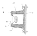
図1は、本発明の実施の一形態である車載用スピーカ装置21の概略的な取付構造を示す。本実施形態では、車載用スピーカ装置21として、スピーカユニット22をスピーカボックス23内に装着した状態を使用する。スピーカボックス23は、たとえば車両の車体の内装材や、車体の外側の側板などの壁面材24の表面に装着される。スピーカボックス23の周囲は、スピーカユニット22からの音響出力が導出される部分を除いて、フェルト等の振動吸収体で形成される緩衝材25で覆われる。これによって、たとえばスピーカボックス23の背面側には、壁面材24との間に、緩衝材25が介在することになる。スピーカボックス23の壁面材24への固定は、保持部材26によって車室27内側から行われる。保持部材26は、車室27に臨む内装材や意匠部品であり、美観に留意して合成樹脂材料などで形成される。保持部材26でスピーカボックス23から音響出力が導出される部分には開口部28が設けられ、車室27への音響出力を損わないようにしている。ただし、通気性のあるネットや、目の粗い布、グリルなどで開口部28を覆う場合もある。保持部材25の周囲は、ボルト29で壁面材24に固定される。ボルト29の固定は、ナットを用いたり、壁面材24に雌ねじを形成して行うことができる。
【0017】
スピーカユニット22が通常のコーン振動板やドーム振動板など、振動板から直接音響放射を行う形式であれば、スピーカボックス23からの音響放射は、スピーカユニット22の取付部前面から行われる。振動板からホーンに音響出力を導く形式であれば、ホーンの開口部から音響放射が行われる。スピーカボックス23にバスレフポートなどが設けられていれば、バスレフポートなどからも音響放射が行われる。緩衝材25は、これらの音響放射部分を除いて、スピーカボックス23を覆うようにする。
【0018】
高音用のスピーカユニット22では、スピーカボックス23を使用しないで、スピーカユニット22を直接緩衝材25で覆って取付けることもできる。高音再生時には、スピーカユニット22のフレームの背面側が閉じていても、バックキャビティが充分確保される(高音の場合、小さい容積で充分である)からである。
【0019】
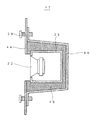
図2は、本発明の実施の他の形態である車載用スピーカ31の概略的な取付構造を示す。本実施形態で図1の実施形態に対応する部分には同一の参照符を付し、重複する説明を省略する。本実施形態では、スピーカボックス23を車体の内装材や側板などの壁面材34に設けられる凹所34aを利用して固定する。凹所34aの大きさは、スピーカボックス23より大きく、スピーカボックス23の周囲には緩衝材35を充填することができるようにしておく。緩衝材35は、図1の緩衝材25と同等のものを使用する。ただし、凹所34aの深さは、必ずしもスピーカボックス23の全体を収納しうる必要はない。凹所34aの車室27側から、内装材や意匠部品としての保持部材36で緩衝材35を押圧し、スピーカボックス23を固定する。保持部材36で、スピーカボックス23からの音響出力が発生される部分に臨む部分は、開口部38として開口している。
【0020】
本実施形態で、凹所34aがスピーカボックス23の全体を収納しうる深さを有していれば、平坦な保持部材36で覆い、車載用スピーカ31が車室27側に突出しないようにすることができる。したがって、たとえば高音用の小型の車載用スピーカ31を、図4に示すようなインスツルメントパネル6などに埋込み、車室27には突出させないで、再生音質の改善も図ることができる。
【0021】
図3は、本発明の実施のさらに他の形態である車載用スピーカ41の概略的な取付構造を示す。本実施形態で図1の実施形態に対応する部分には同一の参照符を付し、重複する説明を省略する。本実施形態では、スピーカボックス23を車体の内装材などの壁面材44の背後側に装着する。スピーカボックス23の周囲は緩衝材45で覆う。緩衝材45は、図1の緩衝材25と同等のものを使用する。緩衝材45の背後側から保持部材46で押圧し、緩衝材45を介して、スピーカボックス23を壁面材44の車室27外部に固定する。壁面材44には、スピーカボックス23からの音響出力が発生される部分に臨む部分は、開口部48として開口している。本実施形態でも、車室27には、突出部分が無いようにすることができる。
【0022】
以上説明した各実施形態で、車載用スピーカ21,31,41は、音響再生部分を除いて全体を緩衝材25,35,45でそれぞれ覆われ、保持部材26,36,46によって緩衝材25,35,45が押圧されて、壁面材24,34,44にそれぞれ固定される車載用スピーカの取付構造が実現される。車載用スピーカ21,31,41で車室27内に音響再生を行う部分を除く部分は、緩衝材25,35,45で覆われるので、スピーカユニット22が空気に対して音響再生する際の反力が与えられて振動等が生じても、振動等による音響出力は緩衝材25,35,45で減衰され、再生される音響出力には含まれなくなって、再生音の音質を向上させることができる。
【0023】
また各実施形態では、音響再生を、音声の主要成分が含まれる中音域の周波数帯、または該中音域の周波数帯よりも高い高音域の周波数帯で行うことが好ましい。音響再生を、音声の主要成分が含まれる中音域の周波数帯域や、さらに高い周波数帯域である高音域で行えば、ボーカルの音質を改善することができるばかりではなく、スピーカボックス23として必要な内容積が小さくなるので、緩衝材25,35,45の使用量を少なくし、保持部材26,36,46を小型にして、コスト低減を図ることができる。
【0024】
【発明の効果】
以上のように本発明によれば、スピーカユニットが装着されたスピーカボックスは、車室内に音響出力部分を除く全体が緩衝材で覆われるので、スピーカボックスに音響出力する際の反力が与えられて振動等が生じても、振動等による音響を緩衝材で減衰させ、スピーカユニットから出力される音響には含まれなくして、再生音の音質を向上させることができる。
【0025】
また本発明によれば、車体の凹所内の車載用スピーカの周囲には緩衝材が充填され、この緩衝材が保持部材によって車室側から押圧されるので、凹所の開口部分に保持部材が存在し、スピーカボックスを確実に保持することができる。
【0027】
また本発明によれば、中音や高音の再生を高音質で行うことができ、緩衝材の使用量を少なくし、保持部材を小型にして、コスト低減を図ることができる。
さらに本発明によれば、スピーカボックスがスピーカユニットの音響放射部分を除いて緩衝材で覆われるので、スピーカボックスが空気に対して音響再生する際の反力が与えられて振動等が生じても、振動等による音響出力を緩衝材で減衰させ、車載用スピーカから再生される音響出力には含まれなくして、再生音の音質を向上させることができる。
また本発明によれば、音声の主要部分が含まれる中音や高音の再生を高音質で行うことができ、緩衝材の使用量を少なくし、保持部材を小型にして、コスト低減を図ることができる。
【図面の簡単な説明】
【図1】本発明の実施の一形態である車載用スピーカ21の取付構造の概要を示す簡略化した断面図である。
【図2】本発明の実施の他の形態である車載用スピーカ31の取付構造の概要を示す簡略化した断面図である。
【図3】本発明の実施のさらに他の形態である車載用スピーカ41の取付構造の概要を示す簡略化した断面図である。
【図4】従来からの車載用スピーカの車両への配置を示す簡略化した平面図である。
【図5】従来からの車載用スピーカの取付構造を示す簡略化した断面図である。
【符号の説明】
21,31,41 車載用スピーカ
22 スピーカユニット
23 スピーカボックス
24,34,44 壁面材
25,35,45 緩衝材
26,36,46 保持部材
27 車室
28,38,48 開口部
29 ボルト
34a 凹所[0001]
BACKGROUND OF THE INVENTION
The present invention relates to a mounting structure of the vehicle-mounted speaker and its performing sound reproduction in the passenger compartment attached to the vehicle.
[0002]
[Prior art]
As shown in FIG. 4, conventionally, a vehicle-mounted speaker such as a car audio is mounted on a
[0003]
5A and 5B show a structure for attaching the vehicle-mounted
[0004]
In relation to mounting a speaker for sound reproduction in a vehicle, Japanese Patent Laid-Open No. 5-276588 discloses a prior art in which a bass reproduction device is arranged in an armrest provided in a passenger compartment of a passenger car or the like. Yes. Japanese Patent Application Laid-Open No. 11-54963 discloses a prior art that uses a cushioning material so as to cover the periphery of the mounting hole when an electronic device mounted on a vehicle or the like is attached. Japanese Patent Laid-Open No. 5-187422 discloses a prior art in which a screw grommet used when fixing a spare tire in a vehicle trunk room or the like is mounted using a cushioning material. Japanese Patent Laid-Open No. 5-56830 discloses a prior art in which a speaker that performs sound reproduction for a person sitting in a seat is covered with a foamed elastic material that is a core material of a chair cover used for a seat chair or the like. Yes.
[0005]
[Problems to be solved by the invention]
The vehicle-mounted speaker needs to perform comfortable sound reproduction in the vehicle interior. For comfortable sound reproduction, it is important that not only the sound quality on the frequency characteristics of the reproduced sound but also the excessive sound quality is good. The excessive sound quality of the reproduced sound is impaired when sound is reproduced from other than the diaphragm of the speaker when the sound output is reproduced from the speaker. Other than the speaker diaphragm, the sound is reproduced by the reaction force that the speaker diaphragm receives when radiating sound output to the air, causing the frame of the speaker unit and the electroacoustic converter such as a magnetic circuit to vibrate. Or when the vibration is transmitted to the speaker box.
[0006]
If the speaker is covered with a foamed elastic body such as a chair cover as in the prior art disclosed in JP-A-5-56830, unnecessary acoustic radiation from other than the diaphragm of the speaker can be prevented. It is expected. However, in this prior art, since a speaker is embedded in a chair cover to be mounted on a seat chair, if it is applied to the
[0007]
An object of the present invention is to provide a mounting structure of a vehicle-mounted speaker and its not generate unwanted acoustic signal.
[0008]
[Means for Solving the Problems]
The present invention includes a speaker unit having a sound output portion for generating sound,
A speaker box for holding the speaker unit;
A cushioning material interposed around the speaker box and covering the speaker unit except for the sound output portion;
A holding member that presses the cushioning material and holds the speaker box on a wall surface material of a vehicle body in a state where the sound output portion faces the passenger compartment.
The speaker box is a mounting structure for a vehicle-mounted speaker, wherein the speaker box is held by the wall surface material so that the sound output portion faces an opening formed in the wall surface material or the holding member .
[0009]
According to the present invention, the speaker box speaker unit is mounted is covered with buffer material, the sound output unit content the speaker box to the vehicle body wall material in a state where the buffer material is pressed by the holding member is in the passenger compartment It is held as it is faced. The portions other than the portion that outputs sound in the vehicle compartment in the speaker box are covered and held with the cushioning material pressed by the holding member, so that the reaction when the speaker unit outputs sound to the air is kept. Even if vibration is generated due to force, sound due to vibration is attenuated by the buffer material and is not included in the sound output from the sound output portion of the speaker unit, so that the sound quality of the reproduced sound can be improved. it can.
[0010]
In the present invention, at least a portion of the front kiss speaker box, is accommodated in a recess provided in an opening facing the passenger compartment in the wall material,
The cushioning material is filled around the speaker box in said recess,
The holding member is characterized by pressing the cabin side or we said cushioning material.
[0011]
According to the present invention, the speaker box covered with the buffer material can be attached to the wall surface material with the speaker unit mounted by using the recess formed in the vehicle body wall surface material . A buffer material is filled around the speaker box in the recess, and the holding part presses the buffer material in the opening facing the vehicle compartment side of the recess , so that the speaker box can output sound from the speaker unit to the vehicle compartment. Thus, it can be reliably fixed in a state where unnecessary sound is not generated .
[0014]
In the present invention, the sound reproduction by the sound output portion of the speaker unit is performed in a mid-frequency range including a main audio component or in a high-frequency range higher than the mid-frequency range. And
[0015]
According to the present invention, the sound reproduction is performed in the mid-frequency range including the main components of the voice or in the high-frequency range that is a higher frequency range, so that it is possible to reproduce the mid- and high-quality sounds with high sound quality. . In-vehicle speakers that reproduce medium and high frequency bands have a small internal volume required as a speaker box, so that the amount of cushioning material used can be reduced, the holding member can be made smaller, and costs can be reduced. .
Furthermore, the present invention provides a speaker unit having a sound output portion for generating sound ;
A speaker box equipped with the speaker unit;
A cushioning material covering the periphery of the speaker box except for the sound output portion of the speaker unit;
A holding member that presses the buffer material and holds the speaker box on a wall surface of a vehicle body,
The speaker box is an in-vehicle speaker that is held by the wall surface material so that the sound output portion faces an opening formed in the wall surface material or the holding member .
According to the present invention, since the speaker box to which the speaker unit is mounted is covered with the cushioning material except for the sound output portion of the speaker unit, a reaction force when the speaker outputs sound to the air is given. Even if vibration or the like occurs, the sound due to the vibration or the like is attenuated by the buffer material and is not included in the sound output from the speaker, and the sound quality of the reproduced sound can be improved.
In the present invention, the sound reproduction by the sound output portion of the speaker unit is performed in a middle frequency band including a main part of the voice or in a higher frequency band higher than the middle frequency band. And
According to the present invention, the sound reproduction is performed in the middle frequency band including the main components of the voice or in the higher frequency band which is a higher frequency band, so that the middle sound and the higher sound can be reproduced with high sound quality. . In-vehicle speakers that reproduce medium and high frequency bands have a small internal volume required as a speaker box, so that the amount of cushioning material used can be reduced, the holding member can be made smaller, and costs can be reduced. .
[0016]
DETAILED DESCRIPTION OF THE INVENTION
FIG. 1 shows a schematic mounting structure of a vehicle-mounted speaker device 21 according to an embodiment of the present invention. In this embodiment, a state in which the speaker unit 22 is mounted in the speaker box 23 is used as the in-vehicle speaker device 21. The speaker box 23 is mounted on the surface of a
[0017]
If the speaker unit 22 is of a type that directly emits acoustic radiation from a diaphragm such as a normal cone diaphragm or dome diaphragm, acoustic radiation from the speaker box 23 is performed from the front surface of the speaker unit 22 mounting portion. If the acoustic output is guided from the diaphragm to the horn, acoustic radiation is performed from the opening of the horn. If the speaker box 23 is provided with a bass reflex port or the like, acoustic radiation is also emitted from the bass reflex port or the like. The buffer material 25 covers the speaker box 23 except for these acoustic radiation portions.
[0018]
In the loudspeaker unit 22, the speaker unit 22 can be directly covered with the buffer material 25 without using the speaker box 23. This is because, during high sound reproduction, a sufficient back cavity is ensured even if the back side of the frame of the speaker unit 22 is closed (a small volume is sufficient for high sound).
[0019]
FIG. 2 shows a schematic mounting structure of a vehicle-mounted speaker 31 which is another embodiment of the present invention. In this embodiment, parts corresponding to those of the embodiment of FIG. 1 are denoted by the same reference numerals, and redundant description is omitted. In the present embodiment, the speaker box 23 is fixed using a recess 34a provided in a wall surface material 34 such as an interior material or a side plate of the vehicle body. The size of the recess 34 a is larger than that of the speaker box 23, so that the buffer box 35 can be filled around the speaker box 23. As the cushioning material 35, the same cushioning material 25 as in FIG. 1 is used. However, the depth of the recess 34 a does not necessarily need to be able to accommodate the entire speaker box 23. The buffer material 35 is pressed by the holding member 36 as an interior material or a design part from the side of the compartment 27 of the recess 34a, and the speaker box 23 is fixed. A portion of the holding member 36 that faces a portion where the sound output from the speaker box 23 is generated is opened as an opening 38.
[0020]
In this embodiment, if the recess 34a has a depth that can accommodate the entire speaker box 23, the recess 34a is covered with a flat holding member 36 so that the vehicle-mounted speaker 31 does not protrude toward the vehicle compartment 27. be able to. Therefore, for example, a small on-vehicle speaker 31 for high sound can be embedded in an
[0021]
FIG. 3 shows a schematic mounting structure of a vehicle-mounted speaker 41 according to still another embodiment of the present invention. In this embodiment, parts corresponding to those of the embodiment of FIG. 1 are denoted by the same reference numerals, and redundant description is omitted. In the present embodiment, the speaker box 23 is mounted on the back side of a wall surface member 44 such as an interior material of the vehicle body. The periphery of the speaker box 23 is covered with a cushioning material 45. The cushioning material 45 is equivalent to the cushioning material 25 of FIG. The speaker member 23 is pressed from the back side of the cushioning material 45 by the holding member 46, and the speaker box 23 is fixed to the exterior of the vehicle compartment 27 of the wall surface material 44 through the cushioning material 45. A portion facing the portion where the sound output from the speaker box 23 is generated in the wall surface material 44 is opened as an opening 48. Also in the present embodiment, the vehicle compartment 27 can have no protruding portion.
[0022]
In each embodiment described above, the in-vehicle speakers 21, 31, and 41 are entirely covered with the buffer materials 25, 35, and 45, respectively, except for the sound reproduction portion, and the buffer materials 25, 35, and 45 are covered with the holding members 26, 36, and 46, respectively. The mounting structure of the vehicle-mounted speaker which is fixed to the
[0023]
Moreover, in each embodiment, it is preferable that sound reproduction is performed in a mid-frequency range including the main sound components or in a high-frequency range higher than the mid-frequency range. If sound reproduction is performed in the middle frequency band including the main components of the voice or in the higher frequency band, which is a higher frequency band, not only the sound quality of the vocal can be improved, but also the contents necessary for the speaker box 23 Since the product becomes smaller, the amount of use of the cushioning materials 25, 35, 45 can be reduced, the holding members 26, 36, 46 can be made smaller, and the cost can be reduced.
[0024]
【The invention's effect】
As described above, according to the present invention, the speaker box to which the speaker unit is attached is entirely covered with the cushioning material except the sound output portion in the vehicle interior, so that a reaction force when sound is output to the speaker box is given. even if vibration or the like occurs Te, sound due to vibration and the attenuation by cushioning material, then it not included in the acoustic output from the speaker unit, thereby improving the sound quality of the reproduced sound.
[0025]
According to the invention, around the vehicle-mounted speaker in the vehicle body recess cushioning material is filled, the buffer material is pressed from the cabin side by the holding member Runode, the holding member to the opening portion of the recess It exists and can hold a speaker box reliably.
[0027]
Further, according to the present invention, it is possible to reproduce medium sounds and high sounds with high sound quality, reduce the amount of use of the buffer material, reduce the size of the holding member, and reduce the cost.
Furthermore, according to the present invention, since the speaker box is covered with the buffer material except for the sound radiation portion of the speaker unit, even if vibration or the like occurs due to a reaction force when the speaker box reproduces sound against the air. The sound output due to vibration or the like is attenuated by the buffer material and is not included in the sound output reproduced from the vehicle-mounted speaker, so that the sound quality of the reproduced sound can be improved.
In addition, according to the present invention, it is possible to reproduce medium tones and high tones containing the main part of sound with high sound quality, to reduce the amount of use of the cushioning material, to reduce the size of the holding member, and to reduce the cost. Can do.
[Brief description of the drawings]
FIG. 1 is a simplified cross-sectional view showing an outline of a mounting structure of a vehicle-mounted speaker 21 according to an embodiment of the present invention.
FIG. 2 is a simplified cross-sectional view showing an outline of a mounting structure of a vehicle-mounted speaker 31 according to another embodiment of the present invention.
FIG. 3 is a simplified cross-sectional view showing an outline of a mounting structure of a vehicle-mounted speaker 41 according to still another embodiment of the present invention.
FIG. 4 is a simplified plan view showing an arrangement of a conventional vehicle-mounted speaker on a vehicle.
FIG. 5 is a simplified cross-sectional view showing a conventional mounting structure of a vehicle-mounted speaker.
[Explanation of symbols]
21, 31, 41 Car-mounted speaker 22 Speaker unit 23
Claims (5)
前記スピーカユニットを保持するスピーカボックスと、
前記スピーカボックスの周囲に介在し、前記音響出力部分を除いて前記スピーカユニットを覆う緩衝材と、
前記緩衝材を押圧して、前記スピーカボックスを車体の壁面材に前記音響出力部分が車室に臨んだ状態で保持する保持部材とを含み、
前記スピーカボックスは、前記壁面材または保持部材に形成された開口部に前記音響出力部分が臨むように、前記壁面材に保持されることを特徴とする車載用スピーカの取付構造。 A speaker unit having a sound output portion for generating sound;
A speaker box for holding the speaker unit;
A cushioning material interposed around the speaker box and covering the speaker unit except for the sound output portion;
A holding member that presses the cushioning material and holds the speaker box on a wall surface material of a vehicle body in a state where the sound output portion faces the passenger compartment.
The speaker box is held by the wall surface material such that the sound output portion faces an opening formed in the wall surface material or the holding member .
前記緩衝材は、前記凹所内でスピーカボックスの周囲に充填され、
前記保持部材は、車室側から前記緩衝材を押圧することを特徴とする請求項1記載の車載用スピーカの取付構造。At least a portion of the speaker box is housed in a recess provided in the wall surface material so as to face the passenger compartment,
The cushioning material is filled around the speaker box in the recess,
The in-vehicle speaker mounting structure according to claim 1, wherein the holding member presses the buffer material from a vehicle compartment side.
前記スピーカユニットが装着されたスピーカボックスと、
前記スピーカユニットの音響出力部分を除いて前記スピーカボックスの周囲を覆う緩衝材と、
前記緩衝材を押圧して、前記スピーカボックスを車体の壁面材に保持する保持部材とを含み、
前記スピーカボックスは、前記壁面材または保持部材に形成された開口部に前記音響出力部分が臨むように、前記壁面材に保持されることを特徴とする車載用スピーカ。 A speaker unit having a sound output portion for generating sound ;
A speaker box equipped with the speaker unit;
A cushioning material covering the periphery of the speaker box except for the sound output portion of the speaker unit;
A holding member that presses the buffer material and holds the speaker box on a wall surface of a vehicle body,
The in-vehicle speaker , wherein the speaker box is held by the wall surface material so that the sound output portion faces an opening formed in the wall surface material or the holding member .
Priority Applications (6)
| Application Number | Priority Date | Filing Date | Title |
|---|---|---|---|
| JP2002167799A JP4170024B2 (en) | 2002-06-07 | 2002-06-07 | In-vehicle speaker and its mounting structure |
| CNB031381170A CN1285469C (en) | 2002-06-07 | 2003-05-27 | Mounting structure of speaker for vehicle |
| US10/449,610 US6896097B2 (en) | 2002-06-07 | 2003-06-02 | Mounting structure of speaker for vehicle |
| CA002430903A CA2430903C (en) | 2002-06-07 | 2003-06-03 | Mounting structure of speaker for vehicle |
| EP03253503A EP1370109A3 (en) | 2002-06-07 | 2003-06-04 | Mounting structure of speaker for vehicle |
| KR10-2003-0036290A KR100517369B1 (en) | 2002-06-07 | 2003-06-05 | Mounting structure of speaker for vehicle |
Applications Claiming Priority (1)
| Application Number | Priority Date | Filing Date | Title |
|---|---|---|---|
| JP2002167799A JP4170024B2 (en) | 2002-06-07 | 2002-06-07 | In-vehicle speaker and its mounting structure |
Publications (3)
| Publication Number | Publication Date |
|---|---|
| JP2004009924A JP2004009924A (en) | 2004-01-15 |
| JP2004009924A5 JP2004009924A5 (en) | 2005-10-13 |
| JP4170024B2 true JP4170024B2 (en) | 2008-10-22 |
Family
ID=29545898
Family Applications (1)
| Application Number | Title | Priority Date | Filing Date |
|---|---|---|---|
| JP2002167799A Expired - Fee Related JP4170024B2 (en) | 2002-06-07 | 2002-06-07 | In-vehicle speaker and its mounting structure |
Country Status (6)
| Country | Link |
|---|---|
| US (1) | US6896097B2 (en) |
| EP (1) | EP1370109A3 (en) |
| JP (1) | JP4170024B2 (en) |
| KR (1) | KR100517369B1 (en) |
| CN (1) | CN1285469C (en) |
| CA (1) | CA2430903C (en) |
Families Citing this family (30)
| Publication number | Priority date | Publication date | Assignee | Title |
|---|---|---|---|---|
| JP3965366B2 (en) | 2003-03-19 | 2007-08-29 | 富士通テン株式会社 | Speaker unit support structure and speaker system |
| GB2402836B (en) | 2003-06-09 | 2006-12-20 | Fujitsu Ten Ltd | Speaker apparatus |
| US7614479B2 (en) * | 2004-05-12 | 2009-11-10 | Jan Plummer | Sound enhancement module |
| US7600608B2 (en) * | 2004-09-16 | 2009-10-13 | Wenger Corporation | Active acoustics performance shell |
| TWI273857B (en) * | 2005-09-29 | 2007-02-11 | Asustek Comp Inc | Speaker with vibration-proof design |
| US20070251759A1 (en) * | 2006-04-26 | 2007-11-01 | Eric Neiman | Bass speaker stand |
| US20080006477A1 (en) * | 2006-07-06 | 2008-01-10 | La Rouge International Co., Ltd. | Sandwich speaker cabinet |
| JP4953847B2 (en) * | 2007-02-06 | 2012-06-13 | 富士通テン株式会社 | Sound generator, sheet, and method of manufacturing sound generator |
| US20090211840A1 (en) * | 2008-02-23 | 2009-08-27 | Peigen Jiang | Loudspeaker Enclosure |
| CN101547385A (en) * | 2008-03-24 | 2009-09-30 | 鸿富锦精密工业(深圳)有限公司 | Vibration absorber and audio device using same |
| US8857559B2 (en) * | 2011-06-14 | 2014-10-14 | Chris Reviel | Speaker cabinet and method for fabrication |
| DE102011115278A1 (en) * | 2011-09-29 | 2013-04-04 | Audi Ag | Speaker system for a motor vehicle |
| TWI433548B (en) * | 2011-12-16 | 2014-04-01 | Wistron Corp | Speaker device and electronic device having the same |
| DE102012106144B4 (en) * | 2012-07-09 | 2014-04-24 | Fujitsu Technology Solutions Intellectual Property Gmbh | Holder for a speaker module and arrangement |
| US8662247B1 (en) * | 2012-08-17 | 2014-03-04 | Guzauski-Swist Audio Systems, Llc | Bracket assembly for an audio loudspeaker system |
| EP2804394B1 (en) * | 2013-05-17 | 2018-08-08 | Harman Becker Automotive Systems GmbH | Method for mounting a loudspeaker carrier in a vehicle and corresponding loudspeaker assembly |
| US8985268B2 (en) * | 2013-05-31 | 2015-03-24 | David A. Wilson | Speaker enclosure frame |
| CN104837084A (en) * | 2015-04-30 | 2015-08-12 | 成都锐奕信息技术有限公司 | Sound-chamber-type wireless positioning terminal |
| JP6424963B2 (en) * | 2015-08-04 | 2018-11-21 | ヤマハ株式会社 | Voice output device |
| EP3258703A1 (en) * | 2016-06-14 | 2017-12-20 | Alpine Electronics, Inc. | Loudspeaker system for a vehicle and vehicle structure comprising such loudspeaker system |
| CN108778796B (en) * | 2016-09-21 | 2022-01-21 | 翰昂汽车零部件有限公司 | Vehicle air conditioning system |
| CN106782473A (en) * | 2016-12-20 | 2017-05-31 | 山东国金汽车工程技术有限公司 | A kind of bass electric horn high being easily installed |
| FR3068659B1 (en) * | 2017-07-05 | 2020-10-23 | Psa Automobiles Sa | LAYOUT OF A BOOT PANEL IN A MOTOR VEHICLE BOOT |
| CN108337612B (en) * | 2018-01-04 | 2020-09-18 | 瑞声科技(新加坡)有限公司 | Sound production device |
| WO2019146096A1 (en) * | 2018-01-29 | 2019-08-01 | ヤマハ株式会社 | Audio output device |
| FR3079475B1 (en) * | 2018-04-03 | 2021-04-16 | Psa Automobiles Sa | ACOUSTIC WARNING SYSTEM EQUIPPING A MOTOR VEHICLE |
| CN109941202B (en) * | 2019-03-05 | 2022-05-27 | 天津博顿电子有限公司 | Rotatable car stereo set |
| US11451903B2 (en) | 2020-01-20 | 2022-09-20 | Epos Group A/S | System for reducing vibrations in loudspeaker |
| RU208879U1 (en) * | 2021-01-15 | 2022-01-19 | Закрытое акционерное общество Научно-производственный центр Фирма «НЕЛК» | Shielded acoustic device |
| CN115396760A (en) * | 2021-05-20 | 2022-11-25 | 英业达科技有限公司 | Loudspeaker |
Family Cites Families (22)
| Publication number | Priority date | Publication date | Assignee | Title |
|---|---|---|---|---|
| US2233459A (en) * | 1937-05-29 | 1941-03-04 | Rca Corp | Acoustic apparatus for motor driven vehicles |
| US4127751A (en) * | 1975-11-27 | 1978-11-28 | Pioneer Electronic Corporation | Loudspeaker with rigid foamed back-cavity |
| DE2637487A1 (en) * | 1976-08-20 | 1978-02-23 | Blaupunkt Werke Gmbh | SPEAKER ENCLOSURE FOR VEHICLES |
| JPS596697A (en) * | 1982-07-05 | 1984-01-13 | Nissan Motor Co Ltd | Sound device for vehicle |
| US4727586A (en) * | 1986-07-14 | 1988-02-23 | Johnson Charles A | High fidelity speaker system and assembly |
| JPH01161654U (en) * | 1988-04-30 | 1989-11-09 | ||
| US5046104A (en) * | 1989-11-30 | 1991-09-03 | Cambridge Soundworks, Inc. | Loudspeaker system |
| CH681144A5 (en) * | 1990-07-31 | 1993-01-29 | Matec Holding | Accessory for automobile HI=FI system |
| JPH0556830A (en) * | 1990-12-11 | 1993-03-09 | Sachiko Kosaka | Chair cover for listening to sounds |
| JPH04325338A (en) * | 1991-04-26 | 1992-11-13 | Matsushita Electric Ind Co Ltd | Acoustic reproducing device for vehicle |
| DE4121408A1 (en) * | 1991-06-28 | 1993-01-07 | Nokia Deutschland Gmbh | PLAYBACK FOR MOTOR VEHICLES |
| US5194701A (en) * | 1991-09-11 | 1993-03-16 | N.P.L. Ltd. | Speaker structure |
| JPH0595594A (en) * | 1991-10-01 | 1993-04-16 | Sony Corp | Fitting device for speaker unit |
| JPH05153685A (en) * | 1991-11-27 | 1993-06-18 | Fujitsu Ten Ltd | Sound field controller |
| JP3169250B2 (en) * | 1992-01-09 | 2001-05-21 | 株式会社ニフコ | Screw grommet |
| JPH07264689A (en) * | 1994-03-16 | 1995-10-13 | Fujitsu Ten Ltd | Headrest speaker |
| JPH07261767A (en) * | 1994-03-17 | 1995-10-13 | Osamu Saito | Sound adjusting material |
| JPH0872623A (en) * | 1994-09-06 | 1996-03-19 | Suzuki Motor Corp | Fitting structure of speaker for vehicle |
| JPH1154963A (en) * | 1997-07-29 | 1999-02-26 | Fujitsu Ten Ltd | Attaching structure for electronic equipment |
| US5942734A (en) * | 1998-08-06 | 1999-08-24 | Dresser Industries, Inc. | Noise-attenuating shielding unit and method for loudspeakers |
| JP2003061197A (en) * | 2001-08-15 | 2003-02-28 | Sony Corp | Acoustic device, seat, and transport facilities |
| JP3620043B2 (en) * | 2002-01-25 | 2005-02-16 | 株式会社ホンダアクセス | Vehicle speaker mounting structure |
-
2002
- 2002-06-07 JP JP2002167799A patent/JP4170024B2/en not_active Expired - Fee Related
-
2003
- 2003-05-27 CN CNB031381170A patent/CN1285469C/en not_active Expired - Fee Related
- 2003-06-02 US US10/449,610 patent/US6896097B2/en not_active Expired - Fee Related
- 2003-06-03 CA CA002430903A patent/CA2430903C/en not_active Expired - Fee Related
- 2003-06-04 EP EP03253503A patent/EP1370109A3/en not_active Withdrawn
- 2003-06-05 KR KR10-2003-0036290A patent/KR100517369B1/en not_active IP Right Cessation
Also Published As
| Publication number | Publication date |
|---|---|
| CA2430903A1 (en) | 2003-12-07 |
| CN1285469C (en) | 2006-11-22 |
| JP2004009924A (en) | 2004-01-15 |
| CN1467112A (en) | 2004-01-14 |
| CA2430903C (en) | 2007-04-03 |
| US20030226712A1 (en) | 2003-12-11 |
| EP1370109A2 (en) | 2003-12-10 |
| US6896097B2 (en) | 2005-05-24 |
| KR20030095304A (en) | 2003-12-18 |
| KR100517369B1 (en) | 2005-09-27 |
| EP1370109A3 (en) | 2006-02-15 |
Similar Documents
| Publication | Publication Date | Title |
|---|---|---|
| JP4170024B2 (en) | In-vehicle speaker and its mounting structure | |
| US8130987B2 (en) | Speaker system with a plurality of openings in side walls of each of two speaker boxes | |
| JP2987196B2 (en) | Car sound reproducer | |
| JP3760447B2 (en) | Interactive speaker headrest | |
| JP3880865B2 (en) | Chair with speaker | |
| CZ294786B6 (en) | Passenger vehicle incorporating loudspeakers comprising panel-form acoustic radiating elements | |
| JP2004009924A5 (en) | ||
| JPS6140576B2 (en) | ||
| US5008944A (en) | Loudspeaker system for motor vehicles | |
| JP2004015566A (en) | On-vehicle speaker | |
| JP5726448B2 (en) | Automotive speakers | |
| JPS63211999A (en) | Vehicle speaker device | |
| JPS6316216Y2 (en) | ||
| CN219728048U (en) | Seat and vehicle with same | |
| JPH0213238Y2 (en) | ||
| US20230322139A1 (en) | Seat provided with a microphone for a vhicle | |
| JPH09290692A (en) | On-vehicle speaker | |
| KR0174195B1 (en) | Car speaker assembly | |
| JP5345368B2 (en) | In-vehicle speaker device | |
| JPH0132455Y2 (en) | ||
| JPS599503Y2 (en) | Car speaker system | |
| JPS6316215Y2 (en) | ||
| JPH0132454Y2 (en) | ||
| JPS63211898A (en) | On-vehicle speaker device | |
| JP2009260525A (en) | Speaker system |
Legal Events
| Date | Code | Title | Description |
|---|---|---|---|
| A521 | Written amendment |
Free format text: JAPANESE INTERMEDIATE CODE: A523 Effective date: 20050606 |
|
| A621 | Written request for application examination |
Free format text: JAPANESE INTERMEDIATE CODE: A621 Effective date: 20050606 |
|
| A131 | Notification of reasons for refusal |
Free format text: JAPANESE INTERMEDIATE CODE: A131 Effective date: 20071016 |
|
| A977 | Report on retrieval |
Free format text: JAPANESE INTERMEDIATE CODE: A971007 Effective date: 20071018 |
|
| A521 | Written amendment |
Free format text: JAPANESE INTERMEDIATE CODE: A523 Effective date: 20071217 |
|
| A131 | Notification of reasons for refusal |
Free format text: JAPANESE INTERMEDIATE CODE: A131 Effective date: 20080415 |
|
| A521 | Written amendment |
Free format text: JAPANESE INTERMEDIATE CODE: A523 Effective date: 20080616 |
|
| TRDD | Decision of grant or rejection written | ||
| A01 | Written decision to grant a patent or to grant a registration (utility model) |
Free format text: JAPANESE INTERMEDIATE CODE: A01 Effective date: 20080805 |
|
| A01 | Written decision to grant a patent or to grant a registration (utility model) |
Free format text: JAPANESE INTERMEDIATE CODE: A01 |
|
| A61 | First payment of annual fees (during grant procedure) |
Free format text: JAPANESE INTERMEDIATE CODE: A61 Effective date: 20080806 |
|
| FPAY | Renewal fee payment (event date is renewal date of database) |
Free format text: PAYMENT UNTIL: 20110815 Year of fee payment: 3 |
|
| R150 | Certificate of patent or registration of utility model |
Free format text: JAPANESE INTERMEDIATE CODE: R150 |
|
| FPAY | Renewal fee payment (event date is renewal date of database) |
Free format text: PAYMENT UNTIL: 20110815 Year of fee payment: 3 |
|
| FPAY | Renewal fee payment (event date is renewal date of database) |
Free format text: PAYMENT UNTIL: 20120815 Year of fee payment: 4 |
|
| FPAY | Renewal fee payment (event date is renewal date of database) |
Free format text: PAYMENT UNTIL: 20130815 Year of fee payment: 5 |
|
| FPAY | Renewal fee payment (event date is renewal date of database) |
Free format text: PAYMENT UNTIL: 20140815 Year of fee payment: 6 |
|
| R250 | Receipt of annual fees |
Free format text: JAPANESE INTERMEDIATE CODE: R250 |
|
| R250 | Receipt of annual fees |
Free format text: JAPANESE INTERMEDIATE CODE: R250 |
|
| R250 | Receipt of annual fees |
Free format text: JAPANESE INTERMEDIATE CODE: R250 |
|
| R250 | Receipt of annual fees |
Free format text: JAPANESE INTERMEDIATE CODE: R250 |
|
| LAPS | Cancellation because of no payment of annual fees |