EP2803976B1 - Device and process for measuring the opacity and the nitrogen oxides in exhaust gases - Google Patents
Device and process for measuring the opacity and the nitrogen oxides in exhaust gases Download PDFInfo
- Publication number
- EP2803976B1 EP2803976B1 EP14168055.3A EP14168055A EP2803976B1 EP 2803976 B1 EP2803976 B1 EP 2803976B1 EP 14168055 A EP14168055 A EP 14168055A EP 2803976 B1 EP2803976 B1 EP 2803976B1
- Authority
- EP
- European Patent Office
- Prior art keywords
- enclosure
- opacity
- nox
- nitrogen oxides
- light beam
- Prior art date
- Legal status (The legal status is an assumption and is not a legal conclusion. Google has not performed a legal analysis and makes no representation as to the accuracy of the status listed.)
- Active
Links
- MWUXSHHQAYIFBG-UHFFFAOYSA-N nitrogen oxide Inorganic materials O=[N] MWUXSHHQAYIFBG-UHFFFAOYSA-N 0.000 title claims description 145
- 239000007789 gas Substances 0.000 title claims description 120
- 238000000034 method Methods 0.000 title claims description 22
- 230000008569 process Effects 0.000 title claims description 8
- 238000005259 measurement Methods 0.000 claims description 56
- 238000002485 combustion reaction Methods 0.000 claims description 10
- 238000001514 detection method Methods 0.000 claims description 7
- 238000012545 processing Methods 0.000 claims description 7
- 230000004044 response Effects 0.000 claims description 5
- 230000000712 assembly Effects 0.000 claims description 4
- 238000000429 assembly Methods 0.000 claims description 4
- 238000007639 printing Methods 0.000 claims description 3
- 229910044991 metal oxide Inorganic materials 0.000 claims description 2
- 150000004706 metal oxides Chemical class 0.000 claims description 2
- 239000011224 oxide ceramic Substances 0.000 claims 1
- 229910002089 NOx Inorganic materials 0.000 description 51
- 239000002245 particle Substances 0.000 description 25
- 239000003570 air Substances 0.000 description 12
- 239000003344 environmental pollutant Substances 0.000 description 12
- 231100000719 pollutant Toxicity 0.000 description 12
- JCXJVPUVTGWSNB-UHFFFAOYSA-N nitrogen dioxide Inorganic materials O=[N]=O JCXJVPUVTGWSNB-UHFFFAOYSA-N 0.000 description 11
- 239000000523 sample Substances 0.000 description 10
- 238000005516 engineering process Methods 0.000 description 8
- 230000003287 optical effect Effects 0.000 description 8
- 239000007787 solid Substances 0.000 description 7
- IJGRMHOSHXDMSA-UHFFFAOYSA-N Atomic nitrogen Chemical compound N#N IJGRMHOSHXDMSA-UHFFFAOYSA-N 0.000 description 5
- QVGXLLKOCUKJST-UHFFFAOYSA-N atomic oxygen Chemical compound [O] QVGXLLKOCUKJST-UHFFFAOYSA-N 0.000 description 5
- 230000008901 benefit Effects 0.000 description 5
- 238000007689 inspection Methods 0.000 description 5
- 239000000203 mixture Substances 0.000 description 5
- 239000001301 oxygen Substances 0.000 description 5
- 229910052760 oxygen Inorganic materials 0.000 description 5
- 230000001105 regulatory effect Effects 0.000 description 5
- 239000012080 ambient air Substances 0.000 description 4
- 230000007423 decrease Effects 0.000 description 4
- 230000000694 effects Effects 0.000 description 4
- 238000010521 absorption reaction Methods 0.000 description 3
- 230000001133 acceleration Effects 0.000 description 3
- 230000033228 biological regulation Effects 0.000 description 3
- 230000005540 biological transmission Effects 0.000 description 3
- 239000003517 fume Substances 0.000 description 3
- 230000006870 function Effects 0.000 description 3
- 238000000053 physical method Methods 0.000 description 3
- 239000000779 smoke Substances 0.000 description 3
- 239000004071 soot Substances 0.000 description 3
- MGWGWNFMUOTEHG-UHFFFAOYSA-N 4-(3,5-dimethylphenyl)-1,3-thiazol-2-amine Chemical compound CC1=CC(C)=CC(C=2N=C(N)SC=2)=C1 MGWGWNFMUOTEHG-UHFFFAOYSA-N 0.000 description 2
- 239000000919 ceramic Substances 0.000 description 2
- 230000001427 coherent effect Effects 0.000 description 2
- 238000005520 cutting process Methods 0.000 description 2
- WFPZPJSADLPSON-UHFFFAOYSA-N dinitrogen tetraoxide Chemical compound [O-][N+](=O)[N+]([O-])=O WFPZPJSADLPSON-UHFFFAOYSA-N 0.000 description 2
- 238000001914 filtration Methods 0.000 description 2
- 238000010438 heat treatment Methods 0.000 description 2
- 238000004519 manufacturing process Methods 0.000 description 2
- 229910052757 nitrogen Inorganic materials 0.000 description 2
- 230000009257 reactivity Effects 0.000 description 2
- 230000009467 reduction Effects 0.000 description 2
- 230000035945 sensitivity Effects 0.000 description 2
- 230000003068 static effect Effects 0.000 description 2
- 238000010998 test method Methods 0.000 description 2
- 230000001131 transforming effect Effects 0.000 description 2
- XLYOFNOQVPJJNP-UHFFFAOYSA-N water Substances O XLYOFNOQVPJJNP-UHFFFAOYSA-N 0.000 description 2
- 239000011358 absorbing material Substances 0.000 description 1
- 230000015572 biosynthetic process Effects 0.000 description 1
- 239000003738 black carbon Substances 0.000 description 1
- 238000004364 calculation method Methods 0.000 description 1
- 230000015556 catabolic process Effects 0.000 description 1
- 239000003054 catalyst Substances 0.000 description 1
- 230000008859 change Effects 0.000 description 1
- 238000009833 condensation Methods 0.000 description 1
- 230000005494 condensation Effects 0.000 description 1
- 238000010276 construction Methods 0.000 description 1
- 230000008094 contradictory effect Effects 0.000 description 1
- 230000001276 controlling effect Effects 0.000 description 1
- 238000007796 conventional method Methods 0.000 description 1
- 230000002596 correlated effect Effects 0.000 description 1
- 238000006731 degradation reaction Methods 0.000 description 1
- 230000003111 delayed effect Effects 0.000 description 1
- 108700041286 delta Proteins 0.000 description 1
- 238000013461 design Methods 0.000 description 1
- 229910001873 dinitrogen Inorganic materials 0.000 description 1
- 239000006185 dispersion Substances 0.000 description 1
- 235000021183 entrée Nutrition 0.000 description 1
- 238000009434 installation Methods 0.000 description 1
- 230000003993 interaction Effects 0.000 description 1
- 239000000463 material Substances 0.000 description 1
- 238000000691 measurement method Methods 0.000 description 1
- 230000035484 reaction time Effects 0.000 description 1
- 230000004043 responsiveness Effects 0.000 description 1
- 238000005070 sampling Methods 0.000 description 1
- 239000007921 spray Substances 0.000 description 1
- 230000007480 spreading Effects 0.000 description 1
- 238000003892 spreading Methods 0.000 description 1
- 238000003860 storage Methods 0.000 description 1
- 230000009466 transformation Effects 0.000 description 1
Images


Classifications
-
- G—PHYSICS
- G01—MEASURING; TESTING
- G01N—INVESTIGATING OR ANALYSING MATERIALS BY DETERMINING THEIR CHEMICAL OR PHYSICAL PROPERTIES
- G01N21/00—Investigating or analysing materials by the use of optical means, i.e. using sub-millimetre waves, infrared, visible or ultraviolet light
- G01N21/17—Systems in which incident light is modified in accordance with the properties of the material investigated
- G01N21/25—Colour; Spectral properties, i.e. comparison of effect of material on the light at two or more different wavelengths or wavelength bands
- G01N21/31—Investigating relative effect of material at wavelengths characteristic of specific elements or molecules, e.g. atomic absorption spectrometry
- G01N21/35—Investigating relative effect of material at wavelengths characteristic of specific elements or molecules, e.g. atomic absorption spectrometry using infrared light
- G01N21/3504—Investigating relative effect of material at wavelengths characteristic of specific elements or molecules, e.g. atomic absorption spectrometry using infrared light for analysing gases, e.g. multi-gas analysis
-
- G—PHYSICS
- G01—MEASURING; TESTING
- G01N—INVESTIGATING OR ANALYSING MATERIALS BY DETERMINING THEIR CHEMICAL OR PHYSICAL PROPERTIES
- G01N21/00—Investigating or analysing materials by the use of optical means, i.e. using sub-millimetre waves, infrared, visible or ultraviolet light
- G01N21/01—Arrangements or apparatus for facilitating the optical investigation
- G01N21/03—Cuvette constructions
- G01N21/031—Multipass arrangements
-
- G—PHYSICS
- G01—MEASURING; TESTING
- G01N—INVESTIGATING OR ANALYSING MATERIALS BY DETERMINING THEIR CHEMICAL OR PHYSICAL PROPERTIES
- G01N21/00—Investigating or analysing materials by the use of optical means, i.e. using sub-millimetre waves, infrared, visible or ultraviolet light
- G01N21/01—Arrangements or apparatus for facilitating the optical investigation
- G01N21/03—Cuvette constructions
- G01N21/05—Flow-through cuvettes
-
- G—PHYSICS
- G01—MEASURING; TESTING
- G01N—INVESTIGATING OR ANALYSING MATERIALS BY DETERMINING THEIR CHEMICAL OR PHYSICAL PROPERTIES
- G01N21/00—Investigating or analysing materials by the use of optical means, i.e. using sub-millimetre waves, infrared, visible or ultraviolet light
- G01N21/17—Systems in which incident light is modified in accordance with the properties of the material investigated
- G01N21/47—Scattering, i.e. diffuse reflection
- G01N21/49—Scattering, i.e. diffuse reflection within a body or fluid
- G01N21/53—Scattering, i.e. diffuse reflection within a body or fluid within a flowing fluid, e.g. smoke
- G01N21/534—Scattering, i.e. diffuse reflection within a body or fluid within a flowing fluid, e.g. smoke by measuring transmission alone, i.e. determining opacity
-
- G—PHYSICS
- G01—MEASURING; TESTING
- G01N—INVESTIGATING OR ANALYSING MATERIALS BY DETERMINING THEIR CHEMICAL OR PHYSICAL PROPERTIES
- G01N33/00—Investigating or analysing materials by specific methods not covered by groups G01N1/00 - G01N31/00
- G01N33/0004—Gaseous mixtures, e.g. polluted air
- G01N33/0009—General constructional details of gas analysers, e.g. portable test equipment
- G01N33/0027—General constructional details of gas analysers, e.g. portable test equipment concerning the detector
- G01N33/0036—Specially adapted to detect a particular component
- G01N33/0037—Specially adapted to detect a particular component for NOx
-
- G—PHYSICS
- G01—MEASURING; TESTING
- G01M—TESTING STATIC OR DYNAMIC BALANCE OF MACHINES OR STRUCTURES; TESTING OF STRUCTURES OR APPARATUS, NOT OTHERWISE PROVIDED FOR
- G01M15/00—Testing of engines
- G01M15/04—Testing internal-combustion engines
- G01M15/10—Testing internal-combustion engines by monitoring exhaust gases or combustion flame
- G01M15/102—Testing internal-combustion engines by monitoring exhaust gases or combustion flame by monitoring exhaust gases
-
- G—PHYSICS
- G01—MEASURING; TESTING
- G01N—INVESTIGATING OR ANALYSING MATERIALS BY DETERMINING THEIR CHEMICAL OR PHYSICAL PROPERTIES
- G01N21/00—Investigating or analysing materials by the use of optical means, i.e. using sub-millimetre waves, infrared, visible or ultraviolet light
- G01N21/01—Arrangements or apparatus for facilitating the optical investigation
- G01N21/03—Cuvette constructions
- G01N21/031—Multipass arrangements
- G01N2021/0314—Double pass, autocollimated path
-
- Y—GENERAL TAGGING OF NEW TECHNOLOGICAL DEVELOPMENTS; GENERAL TAGGING OF CROSS-SECTIONAL TECHNOLOGIES SPANNING OVER SEVERAL SECTIONS OF THE IPC; TECHNICAL SUBJECTS COVERED BY FORMER USPC CROSS-REFERENCE ART COLLECTIONS [XRACs] AND DIGESTS
- Y02—TECHNOLOGIES OR APPLICATIONS FOR MITIGATION OR ADAPTATION AGAINST CLIMATE CHANGE
- Y02A—TECHNOLOGIES FOR ADAPTATION TO CLIMATE CHANGE
- Y02A50/00—TECHNOLOGIES FOR ADAPTATION TO CLIMATE CHANGE in human health protection, e.g. against extreme weather
- Y02A50/20—Air quality improvement or preservation, e.g. vehicle emission control or emission reduction by using catalytic converters
Definitions
- the present invention belongs to the field of the control of pollutant emissions by a motor vehicle with a combustion engine, and more particularly to the field of devices for measuring the pollutants present in the gases emitted by the exhaust line.
- It relates to a measuring device that makes it possible to perform combined measurements of the content of nitrogen oxides (or NOx) in the exhaust gas, and their opacity, which is representative of the content of particles.
- a thermal engine emits during its operation various pollutants, including solid particles of different sizes, mainly soot particles responsible for the formation of black fumes (also called Black Carbon).
- the gaseous flow emitted also comprises different molecules in the gaseous state whose harmfulness requires strict control.
- these are nitrogen oxides, whether nitric oxide NO or nitrogen dioxide NO 2 .
- opacity which consists in measuring the opacity (inverse of the transparency) of the gases resulting from the combustion of diesel engines.
- Technical inspection centers and garages use opacimeters that meet the standards currently in force.
- Opacimeters are commonly made of a measuring chamber in which the exhaust gases circulate.
- the chamber is provided with a light source at one end and a receiver at the other end.
- N 100 (e- KL ) with N: opacity (in%)
- K absorption coefficient (in m -1 )
- L length of exhaust gas through which the light beam passes (in m)
- I R luminous intensity of the transmitter
- Is light intensity received by the receiver
- Another method can be used, based on detection of NOx absorption in the infrared. It requires bringing the gas stream to an analyzer comprising a detection cell coupled to a reference cell containing the pure gas or gases. Regular calibration with a standard gas is necessary. This technology is little used because of interferences related to the humidity of gases.
- OBD On Board Diagnostic
- the system is designed to receive information on the operation of the engine and pollutant emissions, from which it controls the means of regulation of all components of the engine affecting pollutant emissions during operation.
- the quantity of nitrogen oxides emitted is measured continuously by a NOx probe at the exhaust line and this physical measurement is used by the on-board computer to control the opening or closing of the EGR valve.
- the opacity measuring devices and NOx measuring devices currently used by car manufacturers for vehicle approval are not suitable for measurement on all vehicles, including diesel vehicles, in garages and motor homes.
- technical control centers They perform at best two separate measurements, on gases emitted successively. They do not make it possible to carry out measurements of the content of particles and of nitrogen oxides on the same gaseous volume. As a result, the measurements are not correlated, and the results obtained can not give reliable information as part of the technical control.
- the present invention therefore aims to provide a technology that allows simultaneous measurement of opacity (representative of the particle content of black smoke) and a measurement of nitrogen oxide content on the same gaseous fraction taken from an exhaust line of a motor vehicle, this with a precision meeting the most recent pollution standards.
- Another objective of the invention is to meet the standards becoming increasingly severe and requiring an increasingly accurate measurement of pollutant levels increasingly low.
- the device must make it possible to provide an opacity measurement adapted to the emission levels of heat engines, in particular diesel engines, with improved accuracy.
- the measurement of NOx must be carried out in the aggressive environment of the exhaust gases (fouling, temperature), without degradation of the device or loss of sensitivity.
- An object of the invention is also to allow to control the correct operation of the engine and its exhaust gas pollution control systems according to these two simultaneously determined levels.
- the possibility of determining whether an antipollution system is in default by association, comparison or cross-checking of the opacity measurements and the nitrogen oxide content at the exhaust outlet, with information taken from the electronic system. onboard diagnostics (EOBD or OBD).
- EOBD onboard diagnostics
- this measurement must be able to be performed with a very short response time, less than one second, to allow an efficient and fast interaction with the on-board electronic system.
- exhaust gas refers to the essentially gaseous flow emitted by a combustion engine. It is a complex mixture containing both gaseous bodies and solid particles entrained in the gas stream. By convention, this singular term will subsequently be used to designate a given mixture emitted at a given moment and having a given composition.
- the exhaust line of the engine is diverted to the measuring device, so that at least a fraction of the exhaust gas enters and flows through the chamber before to be evacuated.
- the double measure of opacity and NOx content is carried out on a fraction of the gas passing through the enclosure at a given instant.
- the enclosure is conveniently elongated in shape and circular in section, with a main longitudinal axis (further designated as the axis of the enclosure), but may adopt other equivalent forms for the desired functions, for example adopt a section square. It can be equipped with other members arranged on the tubular base structure.
- It comprises in particular a gas inlet duct, which is easily connected to the line exhaust during operation of the device, and at least one outlet duct for gas evacuation. It is understood that to obtain a reliable measurement of the opacity of the gaseous medium, the flow of gas must be regular and follow a fairly long path. Advantageously favors a position as far as possible between the inlet and the outlet of the gas.
- the opacity is measured by the loss of intensity of a light beam having passed through the gaseous volume present in the chamber at this moment.
- a light emitting source sends a beam into the enclosure, which is received by a receiver.
- the generated electrical signal is proportional to the opacity, but also to the length of the optical path through the gas. The length of the speaker is determined and fixed.
- the enclosure also has in its wall a recess whose wall defines a cavity open towards the interior volume of the enclosure. This cavity accommodates the nitrogen oxide detection means, or at least a part thereof, so that they are in contact with the gas flow circulating in the chamber without however cutting the light beam and interfere with the opacity measurement.
- the electrical signals generated are transmitted to a central unit able to transform them to give the value of opacity and NOx content recorded.
- Performing these measurements on the same gaseous volume makes it possible to associate a content of particles with a content of nitrogen oxides present in an exhaust gas of a given composition at a given moment, which would not be the case. whether these two measures were carried out separately. This makes it possible to control the pollution of a motor vehicle by balancing two rejected pollutants, namely, in this case, solid particles and nitrogen oxides.
- the light beam transmitting and receiving means are arranged at a first end of the enclosure, and reflection means of said beam are arranged at a second end of the enclosure. the enclosure, so that the emitted light beam crosses twice the enclosure, along a path and a return trajectory, before reaching the receiving means.
- the enclosure comprises, in the extension of said at least one outlet duct, an air intake provided with a fan to create a gas flow passing through the enclosure perpendicularly to its axis between said air intake and said outlet duct.
- the fan thus makes it possible to pass a flow of clean air which fixes an effective length of gas crossed by the light beam for the measurement of opacity.
- the enclosure comprises two assemblies, each consisting of an air intake and an outlet conduit in extension, said assemblies being placed on either side of said duct. inlet and defining a gas flow chamber of defined length Lc. It is therefore not necessary to use a pump to drive the gas through the enclosure to the output of the device. As a result, the system eliminates the need for a pump for the supply of gases. The exhaust gas pressure is sufficient to bring a representative gas sample to the measuring chamber.
- the length Lc of the gas circulation chamber (exhaust gas and ambient air) is less than the length L 1 of the enclosure, the latter comprising at its first and second ends respectively first and second end zones free of exhaust gas.
- the exhaust gas is then prevented from spreading to the ends of the enclosure beyond the laminar flow.
- the optical elements placed at the ends of the enclosure do not undergo fouling.
- the gas inlet duct starts from a sampling probe connected to the exhaust line and opens into the measurement chamber equidistant from the first and second ends of the enclosure.
- the reflection means said light beam comprise a plane mirror placed perpendicularly to the axis of the enclosure in said second end zone of the enclosure. This mirror returns the light beam along the same path in the forward direction and in the return direction. It is placed near the end wall of the enclosure without the need for additional protection.
- the transmitting and receiving means When the transmitting and receiving means are placed at the first end of the enclosure, they may be merged into an integrated transceiver device.
- an integrated device is expensive and difficult to implement from a technical point of view.
- they can also be separated, which has the advantage of being less expensive, provided to overcome a number of difficulties of design and spatial arrangement.
- the present invention provides a simple and inexpensive construction solution, using a plane mirror as a reflective element at the second end of the enclosure.
- the first end zone of the enclosure which is shaped as a box having walls orthogonal to one another, in which the transmission and reception means are located on two different walls, as well as a separating blade which is placed in a plane oriented at 45 ° with respect to said two walls.
- the separating plates are objects known in optics, which filter a part of the incident beam, and reflect another part, in a constant ratio.
- the blade here fulfills its separating function both in the forward direction and in the beam return direction.
- the object of the present invention is a measuring device as described above in which the transmitting and receiving means are arranged in a box provided at the first end of the enclosure, on two walls of said box oriented according to perpendicular planes, and a separating plate is placed in a plane oriented at 45 ° with respect to said two walls on the direct path and on the return path of the light beam, so that each of said direct and return beams is separated into a transmitted beam (ft) and a deviated beam (fd) of fixed relative intensity.
- the transmitted direct beam (F D ) is partly transmitted towards the mirror, and partly deflected in a first direction, then the return beam (F R ) reflected by the mirror, in turn divides into a part transmitted (ft) which remains in the original direction, that of the transmitter and therefore has no effect, and in a deviated part (fd) in another direction pointing to the positon of the receiver.
- the box comprises a reference receiver placed in the axis of the deviated direct beam, and means for transforming the latter into an electrical signal proportional to the light intensity received . Since the intensity ratio between the transmitted and deflected beam is constant, conveniently 50%, the intensity received by the reference receiver is proportional to the intensity of the transmitted direct beam. This makes it possible to check the state of the transmitter to correct opacity values, or replace it when necessary.
- the nitrogen oxide detection means comprise a NOx sensor whose sensitive element is based on a ceramic of a metal oxide, provided with a pair of electrodes. measuring a potential difference or a current proportional to the concentration of NOx in the exhaust gas.
- This nitrogen oxide sensor is advantageously a probe called ceramic technology.
- the probe comprises a first cell in which the nitrogen oxides of the gas are converted to nitrogen monoxides and the free oxygen present in the gas is removed. In a second cell, the nitrogen monoxides are decomposed by a reducing electrode of dinitrogen and oxygen. The amount of oxygen produced is then measured and gives the concentration of nitrogen oxides initially present in the gas.
- the system according to the invention overcomes the filtration operations necessary to dissociate the solid particles NOx before measuring the NOx. It is much less sensitive to fouling.
- Another very significant advantage arising from the choice of this type of sensor is that it does not require calibration with a standard gas, as it can be the case with conventional measuring technologies (infrared, electrochemical or other sensors). Only a recalibration with ambient air may be necessary from time to time, which can be easily automated. It is then made completely transparent to the user since it does not require any particular intervention of a technician and it is not necessary either to have tools or specific equipment (gas bottle standard, regulators, manometer, ). Again, even if it proved necessary to replace it, the calibration after replacement would be done automatically. The replacement of this sensor does not require any other intervention. Moreover, it has an improved life of a ratio 50 compared to the electrochemical solutions used on gas analyzers infrared technology.
- this probe has a very short response time (less than one second) to make measurements very close in time, almost in continuous mode. This will make it possible to continue to use the current test procedure for technical inspections for diesel vehicles (ie measuring pollution peaks during free accelerations), something that is not possible with technologies whose response time is several seconds, as methods based on infrared measurements. It may also be possible, if desired, to have a relevant measurement according to other test procedures that would require a certain reactivity of the measurement, such as the brief loading of the vehicle engine.
- said NOx sensor and said exhaust gas inlet duct are placed at the middle part of the enclosure, the cavity housing the NOx sensor being formed in the upper wall of the enclosure and the sensitive element of said NOx sensor flush with the plane of the wall of the enclosure, while the inlet conduit opens into the enclosure in a substantially horizontal orientation.
- the term "upper part” refers to the one that occupies the highest position when the device is in operation. This avoids the risk of contaminating and damaging the sensor with water spray from the gas and further reduces its fouling.
- the heating elements have a predetermined temperature and / or regulated, so as to prevent water vapor from being deposited on the cold walls.
- the wall of the enclosure is coated with a light absorbing material in the visible frequency band and the light source, so that no unwanted light reflection or transmission. does not reach the receiver.
- the processing means of said first and second electrical signals comprise means for storing and printing the value of the opacity and of the NOx content of said gas. exhaust, measured at the same time of operation of said motor vehicle.
- the measured values of the contents of nitrogen oxides and opacity are transmitted to calculation and recording means which the device is equipped with, for their storage.
- Essentially electronic processing means allow instantaneous or delayed processing of these values.
- a procedure according to the invention is based on the measurement of a difference between, on the one hand, an idle and fast idle speed, and on the other hand an accelerated idle speed and acceleration, which does not impose acquire ancillary equipment such as power benches.
- measurements can be done continuously, not only as regards the opacity, but also with regard to the NOx content, which represents a novel advantage of the device according to the invention.
- it is now possible thanks to the present invention to combine an opacity measurement adapted to the emission levels of the engines and a NOx measurement at the exhaust outlet, and to cross-check them with information taken from the embossed electronics. It is thus possible to implement a measurement protocol defined for engines classified "Euro 5", based on the search for a difference proving a responsiveness of the EGR valve to different operating conditions detected and managed by the engine management computer. .
- the principle is simpler. Indeed these engines are equipped with a NOx probe whose information is used by the onboard computer (EOBD). Data on the NOx contents emitted at different engine speeds are therefore accessible via an EOBD connection to the computer.
- the measurement protocol consists of identifying whether these values seen from the computer are homogeneous and coherent with reality (ie with the measurement performed at the exhaust output). One operates by a comparison between internal information of the vehicle and physical measurement at the output of the exhaust pipe.
- the processing means of said first and second electrical signals comprise means for comparing the values of opacity and measured NOx content with values calculated by a system. electronics regulating the NOx emissions of said motor vehicle. It is thus possible to verify the adequacy between the values recorded by the measuring device according to the invention, with the information and the commands given by the on-board computer of the vehicle, when equipped with it.
- the device according to the invention finds its use in the technical control centers of motor vehicles, during the control of pollutants emitted, as well as in garages or service stations, in France and abroad. It is transportable light and adaptable to its environment. It can also be used to control the pollution control systems present in the vehicle exhaust system.
- the present invention therefore also relates to a method for determining in a fast, reliable and convenient manner for the operator, two parameters whose levels are regulated and subject to the technical control of vehicles.
- the emitted light beam crosses the enclosure twice, in a direct path and a return path, before reaching the receiving means.
- the beam is reflected by a plane mirror, so that the direct path of the beam (direct beam F D ) through the enclosure is identical to the return path (return beam F R ).
- collimation lenses placed judiciously in the optical path are advantageously incorporated in order to focus the light beam on the one hand on the mirror, on the other hand on the receiver, and thus to prevent its dispersion towards the walls of the optical system. pregnant.
- the exhaust gas circulates in the chamber from said inlet duct to at least one outlet duct by driving by a flow of air which is introduced into the enclosure close to each outlet duct by an air intake pulsed by a fan, for creating a laminar flow of gases passing through the enclosure perpendicular to its axis between said air intake and said outlet duct.
- the exhaust gas circulates in the chamber from said inlet duct to two outlet ducts placed on either side of said inlet duct.
- air being introduced into the chamber near the two outlet ducts by two air intakes and pulsed by two fans, to create two laminar flows that cross the enclosure perpendicular to its axis and define a circulation chamber gases of defined length Lc, less than the length Le of the enclosure.
- the gases (exhaust gas and laminar ambient air) therefore circulate only in this circulation chamber, which can be described as virtual, of fixed length and defined by the position of the inlet ducts of the pulsed air in the chamber. enclosure, without clogging the optical elements placed at either end of the enclosure.
- the light beam is emitted by a light source and is received by a receiver which are placed in a first end zone formed at a first end of the enclosure, and the light beam is reflected by a plane mirror which is placed in a second end zone formed at a second end of the enclosure, said first and second end zones being free of exhaust gas.
- the direct beam F D is divided before passing through the enclosure by a separating plate, in a transmitted beam oriented in the axis of the enclosure, and in a beam deflected fd oriented to a reference receiver providing a signal proportional to the intensity of said deflected beam, said transmitted and deflected beams having a determined fixed relative intensity.
- the return light beam F R when the return light beam F R has passed through the enclosure, it is divided by the separating plate into a transmitted beam and into a deflected beam which is directed towards the reception.
- the nitrogen oxides are detected by a NOx sensor flush with the plane of the wall of the enclosure, close to the exhaust gas inlet duct, which opens into the enclosure in its middle part.
- a NOx sensor flush with the plane of the wall of the enclosure, close to the exhaust gas inlet duct, which opens into the enclosure in its middle part.
- the nitrogen oxides are detected with a response time of less than one second.
- the choice of the NOx sensor as defined above is decisive in this respect. This characteristic is essential for a simultaneous measurement of NOx and opacity, measurements can be made instantly, at each change of engine speed.
- any condensation is prevented on the walls of the device. This is why, preferably, one or more of the following enclosure parts are maintained at a controlled temperature: the wall of the enclosure, the wall of the cavity housing the NOx sensor, the terminal zones of the enclosure.
- the light entering the enclosure or reflected by the wall is absorbed by a material covering said wall.
- said first and second electrical signals are transmitted to a central unit and are processed to calculate the opacity and the NOx content of said exhaust gas, measured at the same time of operation of said motor vehicle. They are stored and printed (and / or displayed), so that the operator can see the conformity of the vehicle or recommend an intervention.
- said first and second electrical signals are transmitted to a central unit and are processed by comparing the values of opacity and measured NOx content with values calculated by a system.
- electronics regulating the NOx emissions of said motor vehicle are provided.
- a device for simultaneously measuring the opacity and the nitrogen oxide content of an exhaust gas of a motor vehicle with a combustion engine comprises the chamber 1 with a tubular wall of length The determined and fixed.
- the tubular wall 11 may have any cross section but is more conveniently circular.
- the enclosure 1 is closed at its ends 14, 15 by end walls.
- the enclosure is provided at its first end 14 with a means 5 for emitting a light beam and a means 6 for receiving the light beam at the end of its optical path, which are here combined into a transmitting device integrated receiver ( fig.1 ).
- a separate transmitter and receiver can be used ( Fig. 2 ).
- the receiver is connected to an electrical circuit which transmits the received signal, proportional to the light intensity, to a unit adapted to transform the electrical signal into a quantitative value of the opacity and hence a value of the solid particle content.
- a plane mirror 7 is disposed at the second end 15 of the enclosure 1, so that the emitted light beam passes through the enclosure twice, in the direct path F D and then in a return path F R , before reaching the receiver .
- the light beam has the same path through the measuring chamber in the forward direction and in the return direction.
- the enclosure 1 comprises a recess defining a cavity 13 formed in the upper wall 11 of the enclosure, at its median part.
- a NOx sensor 2 which is designed to detect oxides of nitrogen.
- Its sensitive element 2a is provided with a pair of electrodes measuring a potential difference proportional to the concentration of NOx in the gas and delivering a second electrical signal which is converted to give a quantitative measurement of the nitrogen oxide content of the gas. gas present in the enclosure.
- a commercially available probe is used.
- the sensor 2 is placed in the housing so that its sensitive element 2a is flush with the plane of the wall 11 of the enclosure, without cutting the path of said light beam. Furthermore, the inlet duct 3 opens into the chamber 1 at the same median level as the NOx sensor, but in a substantially horizontal orientation.
- the chamber 1 has an inlet duct 3 which is connected to the exhaust line during operation of the device, and two outlet ducts 4, through which the exhaust gas is discharged.
- An air intake 8 is formed in the extension of each outlet duct 4.
- Each of them is provided with a fan 9 which pulses ambient air to the enclosure and to the outlet ducts 4. and a gas flow passing through the chamber 1 perpendicular to its axis between an air intake 8 and the outlet duct opposite, by laminar flow and which drives the exhaust gas to the outlet.
- This flow is stable so that the gases flow into a virtual measuring chamber of effective length Lc constant and defined by the limit 22 of the two laminar flows.
- the length of gas crossed by the light beam for the opacity measurement is thus twice the length Lc.
- the enclosure thus has at its first and second ends 14, 15, respectively a first and second end zones 24, 25, in which the exhaust gas does not spread. Therefore, the plane mirror 7, disposed at the second end 15 of the chamber 1, receives the light beam, without being in contact with the gas.
- the optical elements transmitter and receiver in particular placed in the first zone at the first end of the enclosure.
- the device can be used both outdoors and indoors and the ambient temperature range from 0 ° C to 50 ° C. The measurement can be done continuously.
- the transmitting means 5 and receiving 6 are arranged in a box 18 formed at the first end 14 of the chamber 1 on two walls of said box oriented in perpendicular planes.
- the transmitter 5 is placed in the main axis of the enclosure on the wall forming the end wall 14, while the receiver is placed on a first side wall 19.
- a reference receiver 16 is placed on a second side wall 20, opposite to the wall 19 where receiver 6 is located.
- the transmitted direct beam (F D ) is partly transmitted to the mirror F D (ft) through the measurement chamber, and partly deflected in a first direction F D (fd) where it will hit the reference receiver 16. Then the return beam (F R ) reflected by the mirror through the measurement chamber, and in turn divides into a transmitted portion F R (ft) which remains in the initial direction which is that of the transmitter and has not therefore no effect, and in a part deviated F R (fd) at right angles to the receiver 6.
- This simple and inexpensive installation does not require complex adjustments. Being located in the terminal area, it is also protected from fumes. In the end, it is very precise, reliable and durable.
- the opacity measurement corresponds to the proportion of soot particles in the gas. These soot particles are mainly contributory to the opacity of the fumes. However, emissions from diesel engines are complex, and different gases are emitted, some of which have significant opacity. In particular NO 2 being a brown-red gas, it could distort very low values of opacity. However, new engines responding to Euro 5 and Euro 6 regulations have opacity values extremely weak. If the particulate content expressed in mg / m 3 is equivalent to the NO 2 contribution , the opacity value due to the particles must be compensated.
- This compensation can be initialized thanks to a calibration point obtained via a gas (standard cylinder) with a high NO2 content. This one-point calibration then makes it possible to provide opacity compensation from the measured NO 2 value.
- the behavior and control of the EGR valve is taken into account.
- the measuring process for the Euro 5 engines is based on the gap search proving the reactivity of the EGR valve at different operating conditions detected and managed by the engine management computer (without NOx sensor).
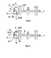
- the scheme of this protocol is illustrated in Fig. 3 .
- phase 1 no-load engine, the measured values are compared with the values given by the EOBD, for different levels of NOx emission (A: high level, B: medium level, C: low level and D: extra low level, N level: EPO value).
- A high level
- B medium level
- C low level
- D extra low level
- N level EPO value
- Fig. 4 The scheme of this protocol is illustrated in Fig. 4 . It is observed causes the opening and closing of the valve by changing the speed (idle or accelerated) and measuring the values of NOx emitted. They are compared to the values given by the on-board computer (EOBD). If they match, the system works.
- EOBD on-board computer
Description
La présente invention appartient au domaine du contrôle des émissions polluantes par un véhicule automobile à moteur thermique, et plus particulièrement au domaine des dispositifs de mesure des matières polluantes présentes dans les gaz émis par la ligne d'échappement.The present invention belongs to the field of the control of pollutant emissions by a motor vehicle with a combustion engine, and more particularly to the field of devices for measuring the pollutants present in the gases emitted by the exhaust line.
Elle a pour objet un dispositif de mesure qui permet de réaliser des mesures combinées de la teneur en oxydes d'azote (ou NOx) dans les gaz d'échappement, et de leur opacité laquelle est représentative de la teneur en particules.It relates to a measuring device that makes it possible to perform combined measurements of the content of nitrogen oxides (or NOx) in the exhaust gas, and their opacity, which is representative of the content of particles.
Un moteur thermique émet durant son fonctionnement divers polluants, dont des particules solides de différentes tailles, majoritairement des particules de suie responsables de la formation des fumées noires (aussi appelées Black Carbon). Le flux gazeux émis comprend également différentes molécules à l'état gazeux dont la nocivité nécessite le contrôle strict. Ce sont en particulier les oxydes d'azote, qu'il s'agisse de monoxyde d'azote NO ou de dioxyde d'azote NO2.A thermal engine emits during its operation various pollutants, including solid particles of different sizes, mainly soot particles responsible for the formation of black fumes (also called Black Carbon). The gaseous flow emitted also comprises different molecules in the gaseous state whose harmfulness requires strict control. In particular, these are nitrogen oxides, whether nitric oxide NO or nitrogen dioxide NO 2 .
C'est pourquoi la législation qui faisait obligation de longue date de réduire les émissions de fumée noire par les moteurs Diesel, va imposer désormais également le contrôle du niveau des NOx en sortie d'échappement. Pour respecter les nouvelles normes Euro 5 et Euro 6, tous les véhicules neufs sont d'ores et déjà équipés d'un filtre à particules.This is why the legislation that had long been obligated to reduce black smoke emissions by diesel engines, will now also impose NOx level control at the exhaust outlet. To comply with the new Euro 5 and Euro 6 standards, all new vehicles are already equipped with a particulate filter.
Le contrôle de la teneur en particules émises dans les gaz d'échappement est communément effectué par opacimétrie, qui consiste à mesurer l'opacité (inverse de la transparence) des gaz issus de la combustion des moteurs Diesel. Les centres de contrôle technique et les garages utilisent des opacimètres répondant aux normes actuellement en vigueur.The control of the content of particles emitted in the exhaust gas is commonly carried out by opacity, which consists in measuring the opacity (inverse of the transparency) of the gases resulting from the combustion of diesel engines. Technical inspection centers and garages use opacimeters that meet the standards currently in force.
Les opacimètres sont communément constitués d'une chambre de mesure dans laquelle les gaz d'échappement circulent. La chambre est munie d'une source lumineuse à une extrémité et d'un récepteur à l'autre extrémité. L'intensité du faisceau lumineux traversant la chambre lorsqu'elle est remplie du gaz dont l'opacité est mesurée, décroît en proportion de l'opacité des gaz, c'est-à-dire de leur coefficient d'absorption conformément à la loi de Beer-Lambert, qui s'énonce par la relation : ![]()
d'où on déduit l'opacité : N = 100 (e-K.L)
avec N : opacité (en %)
K : coefficient d'absorption (en m-1)
L : longueur de gaz d'échappement traversé par le faisceau lumineux (en m)
IR : intensité lumineuse de l'émetteur
Is : intensité lumineuse reçue par le récepteurOpacimeters are commonly made of a measuring chamber in which the exhaust gases circulate. The chamber is provided with a light source at one end and a receiver at the other end. The intensity of the light beam passing through the chamber when it is filled with the gas whose opacity is measured, decreases in proportion to the opacity of the gases, that is to say their absorption coefficient according to the law. of Beer-Lambert, which is stated by the relation: ![]()
from which we deduce the opacity: N = 100 (e- KL )
with N: opacity (in%)
K: absorption coefficient (in m -1 )
L: length of exhaust gas through which the light beam passes (in m)
I R : luminous intensity of the transmitter
Is: light intensity received by the receiver
De cette mesure d'opacité, il est aisé de déterminer la teneur en particules de fumées noires dans le volume gazeux, la proportion de lumière atteignant les moyens de réception étant inversement proportionnelle au taux de particules en suspension dans le gaz traversé. Un tel dispositif de mesure est connu par exemple des demandes de brevet
Au cours des vingt dernières années, les législations ont durci les limites des émissions des véhicules neufs : division par 15 des émissions NOx et par 35 des émissions de particules entre la norme Euro 1 (1993) et Euro 6 (2014). Les nouvelles normes exigent cependant un saut quantitatif important dans la précision des mesures réalisées, ce qui est difficilement réalisable avec les équipements actuels qui ne sont pas en adéquation du point de vue de la précision, de la sensibilité et du niveau minimum devant être détecté en relation avec une gamme de mesure plus faible compatible avec les nouvelles législations d'émission. Au demeurant, les émissions de NOx n'étaient contrôlées jusqu'à présent que sur les moteurs à essence.Over the past 20 years, legislation has tightened the limits of emissions from new vehicles: 15-fold NOx emissions and 35-fold particulate emissions between Euro 1 (1993) and Euro 6 (2014). The new standards, however, require a significant quantitative jump in the accuracy of the measurements made, which is difficult to achieve with current equipment that is not in adequacy with respect to the accuracy, sensitivity and minimum level to be detected in relationship with a lower measurement range compatible with new emission legislation. Moreover, NOx emissions have been controlled so far only on gasoline engines.
La mesure d'oxydes d'azote dans les gaz d'échappement (des moteurs à essence) se fait quant à elle communément à l'aide d'un capteur électrochimique. Son principe repose sur la mesure de la quantité d'oxygène produite par la réduction des NOx à l'aide d'un catalyseur adéquat. Les NOx doivent d'abord être amenés par pompage et séparées du reste des gaz par filtration. Les capteurs électrochimiques standards doivent être remplacés régulièrement et une calibration avec un gaz étalon doit être faite chaque fois, ce qui nécessite un matériel spécifique (bouteilles de gaz étalon, manomètre, détendeurs, ou autre). Cette mesure n'est pas pratiquée pour les moteurs Diesel.The measurement of nitrogen oxides in exhaust gases (gasoline engines) is commonly done using an electrochemical sensor. Its principle is based on measuring the amount of oxygen produced by the reduction of NOx using a suitable catalyst. The NOx must first be pumped and separated from the rest of the gases by filtration. Standard electrochemical sensors must be replaced regularly and calibration with a standard gas must be done each time, which requires specific equipment (standard gas cylinders, manometer, pressure regulators, or other). This measurement is not practiced for diesel engines.
Une autre méthode peut être utilisée, basée sur une détection de l'absorption des NOx dans l'infrarouge. Elle nécessite d'amener le flux gazeux jusqu'à un analyseur comprenant une cellule de détection couplée à une cellule de référence contenant le ou les gaz purs. Une calibration régulière avec un gaz étalon est nécessaire. Cette technologie est peu employée du fait des interférences liées à l'humidité des gaz.Another method can be used, based on detection of NOx absorption in the infrared. It requires bringing the gas stream to an analyzer comprising a detection cell coupled to a reference cell containing the pure gas or gases. Regular calibration with a standard gas is necessary. This technology is little used because of interferences related to the humidity of gases.
Outre les inconvénients inhérents à chacune des méthodes de mesure exposées ci-dessus, un nouveau défit est apparu du fait que les deux types de polluants doivent être réduits de manière conjointe. En effet, si la législation précédemment en vigueur prévoyait une simple mesure de l'opacité pour déterminer le bon fonctionnement du véhicule et son respect de l'environnement, elle impose désormais également le contrôle des émissions d'oxydes d'azote. Dans le même temps, les normes d'émission qui fixent les limites maximales de rejets polluants seront beaucoup plus strictes ce qui demande un appareillage de précision accrue. Par exemple, entre 2000 et 2014, pour l'homologation des véhicules par les constructeurs, le taux admis de NOx émis est passé de 0,5 g/km à 0,08 g/km pour les moteurs à essence, et de 0,15 g/km à 0,06 g/km pour les moteurs Diesels. De même, le taux maximum de particules est désormais de 0,005 g/km, soit dix fois moins qu'en 2000 pour les Diesels, alors qu'il n'était pas réglementé pour les moteurs à essence.In addition to the disadvantages inherent in each of the methods of measurement described above, a new challenge has arisen because both types of pollutants have to be reduced together. Indeed, if the legislation previously in force provided a simple measure of opacity to determine the proper functioning of the vehicle and its respect for the environment, it now also requires the control of emissions of nitrogen oxides. At the same time, emission standards that set maximum limits for pollutant releases will be much stricter, which requires more precision equipment. For example, between 2000 and 2014, for the approval of vehicles by manufacturers, the allowable NOx emission rate increased from 0.5 g / km to 0.08 g / km for gasoline engines, and from 0, 15 g / km at 0.06 g / km for diesel engines. Similarly, the maximum particle rate is now 0.005 g / km, ten times less than in 2000 for diesel engines, while it was not regulated for gasoline engines.
Il devient donc nécessaire de mener une lutte simultanée et conjointe contre ces deux types de polluants.It therefore becomes necessary to conduct a simultaneous and joint fight against these two types of pollutants.
Or, les exigences de dépollution en ce qui concerne respectivement les particules et les oxydes d'azote sont contradictoires, dans la mesure où la majorité des moteurs Diesel est équipée d'un dispositif de réduction des émissions polluantes, appelé vanne RGE pour "recirculation des gaz d'échappement" (ou EGR pour "exhaust gas recirculation"), qui a pour rôle de diminuer les rejets d'oxydes d'azote, mais ce faisant augmente la production de particules. Ce système, qui satisfait à moindre coût aux normes européennes, consiste à rediriger une partie des gaz d'échappement des moteurs à explosion dans le collecteur d'admission. Il a pour effet de ralentir la combustion du mélange et d'absorber une partie des calories, ce qui diminue la température de combustion. De plus, il limite la présence d'oxygène dans le cylindre.However, the pollution control requirements for particles and nitrogen oxides, respectively, are contradictory, insofar as the majority of diesel engines are equipped with a device for reducing pollutant emissions, called the EGR valve for "recirculation of exhaust gas "(or EGR for" exhaust gas recirculation "), whose role is to reduce the release of nitrogen oxides, but in doing so increases the production of particles. This system, which is cheaper to meet European standards, consists of redirecting part of the exhaust gas from the combustion engines to the intake manifold. It has the effect of slowing down the combustion of the mixture and absorbing a portion of the calories, which decreases the combustion temperature. In addition, it limits the presence of oxygen in the cylinder.
Ces deux effets entraînent certes une diminution des oxydes d'azote dans les gaz émis, mais la combustion étant moins poussée, les particules solides sont moins dégradées. Pour trouver un compromis entre la diminution des oxydes d'azote et l'augmentation de particules, les gaz réinjectés sont refroidis. Le fait d'abaisser la température des gaz réinjectés diminue la production des NOx pour le même taux de recirculation des gaz (même ouverture de la vanne RGE). Un équilibre peut être prédéfini, par pilotage de l'ouverture ou de la fermeture de la vanne RGE en fonction du régime du moteur (accélération libre ou faible charge) sans contrôle de l'émission effective des NOx, conformément aux normes dites Euro 5.These two effects certainly lead to a decrease in nitrogen oxides in the gases emitted, but the combustion being less extensive, the solid particles are less degraded. To find a compromise between the reduction of nitrogen oxides and the increase of particles, the reinjected gases are cooled. Lowering the temperature of the re-injected gases decreases NOx production for the same gas recirculation rate (same opening of the EGR valve). An equilibrium can be predefined, by controlling the opening or closing of the EGR valve as a function of the engine speed (free acceleration or low load) without control of the effective NOx emission, in accordance with the so-called Euro 5 standards.
Il peut aussi être recherché en permanence en fonction des différents régimes de fonctionnement du moteur et des émissions de NOx relevées dans la ligne d'échappement, grâce à un système de diagnostic embarqué, plus connu sous le nom de OBD (pour On Board Diagnostic) aux Etats-Unis et d'EOBD en Europe. Le système est conçu pour recevoir des informations sur le fonctionnement du moteur thermique et sur les émissions de polluants, à partir desquelles il commande les moyens de régulation de l'ensemble des composants du moteur thermique affectant les émissions de polluants durant son fonctionnement. Dans ce cas, la quantité d'oxydes d'azote émise est relevée en continu par une sonde NOx au niveau de la ligne d'échappement et cette mesure physique est utilisée par le calculateur de bord pour commander l'ouverture ou la fermeture de la vanne RGE.It can also be constantly searched for different engine operating conditions and NOx emissions in the exhaust line, thanks to an on-board diagnostic system, better known as OBD (On Board Diagnostic). in the United States and EOBD in Europe. The system is designed to receive information on the operation of the engine and pollutant emissions, from which it controls the means of regulation of all components of the engine affecting pollutant emissions during operation. In this case, the quantity of nitrogen oxides emitted is measured continuously by a NOx probe at the exhaust line and this physical measurement is used by the on-board computer to control the opening or closing of the EGR valve.
Il est impératif donc de considérer la teneur en particules simultanément à la teneur en oxydes d'azote et d'opérer une balance entre ces deux teneurs qui évoluent différemment lors du fonctionnement du moteur thermique. Dans ce contexte, il devient primordial de pouvoir mesurer, lors des contrôles techniques des véhicules, à la fois les teneurs en oxyde d'azote et en particules solides, en même temps et sur un même volume gazeux dégagé à un régime donné du moteur.It is therefore imperative to consider the content of particles simultaneously with the content of nitrogen oxides and to operate a balance between these two contents which evolve differently during operation of the engine. In this context, it becomes essential to be able to measure, during the technical inspections of the vehicles, both the contents of nitrogen oxide and solid particles, at the same time and on the same gaseous volume released at a given engine speed.
Les dispositifs de mesure d'opacité et les dispositifs de mesure des NOx utilisés actuellement par les constructeurs automobiles pour l'homologation des véhicules ne sont pas adaptés à la mesure sur tous les véhicules, notamment les véhicules à moteur Diesel, dans les garages et les centres de contrôle technique. Ils réalisent au mieux deux mesures séparées, sur des gaz émis successivement. Ils ne permettent pas d'effectuer les mesures de teneur en particules et en oxydes d'azote sur un même volume gazeux. De ce fait, les mesures ne sont pas corrélées, et les résultats obtenus ne peuvent pas donner pas une information fiable dans le cadre du contrôle technique.The opacity measuring devices and NOx measuring devices currently used by car manufacturers for vehicle approval are not suitable for measurement on all vehicles, including diesel vehicles, in garages and motor homes. technical control centers. They perform at best two separate measurements, on gases emitted successively. They do not make it possible to carry out measurements of the content of particles and of nitrogen oxides on the same gaseous volume. As a result, the measurements are not correlated, and the results obtained can not give reliable information as part of the technical control.
La présente invention a donc pour objectif d'offrir une technologie qui permette d'effectuer simultanément une mesure d'opacité (représentative de la teneur en particules des fumées noires) et une mesure de teneur en oxydes d'azote sur une même fraction gazeuse prélevée à partir d'une ligne d'échappement d'un véhicule automobile, ceci avec une précision répondant aux normes de pollution les plus récentes.The present invention therefore aims to provide a technology that allows simultaneous measurement of opacity (representative of the particle content of black smoke) and a measurement of nitrogen oxide content on the same gaseous fraction taken from an exhaust line of a motor vehicle, this with a precision meeting the most recent pollution standards.
Un autre objectif de l'invention est de répondre aux normes devenant de plus en plus sévères et exigeant une mesure de plus en plus précise sur des teneurs en polluants de plus en plus faibles. Le dispositif devra permettre de fournir une mesure d'opacité adaptée aux niveaux d'émission des moteurs thermiques, notamment des moteurs Diesel, avec une précision améliorée. Egalement, la mesure des NOx doit être réalisée dans l'environnement agressif des gaz d'échappement (encrassement, température), sans dégradation du dispositif ni perte de sensibilité.Another objective of the invention is to meet the standards becoming increasingly severe and requiring an increasingly accurate measurement of pollutant levels increasingly low. The device must make it possible to provide an opacity measurement adapted to the emission levels of heat engines, in particular diesel engines, with improved accuracy. Also, the measurement of NOx must be carried out in the aggressive environment of the exhaust gases (fouling, temperature), without degradation of the device or loss of sensitivity.
Un objectif de l'invention est aussi de permettre de contrôler le fonctionnement correct du moteur thermique et de ses systèmes de dépollution des gaz d'échappement en fonction de ces deux teneurs simultanément déterminées. En particulier est recherchée la possibilité de déterminer si un système antipollution est en défaut, par association, comparaison ou recoupement des mesures d'opacité et de teneur en oxydes d'azote en sortie d'échappement, avec des informations prélevées à partir du système électronique de diagnostic embarqué (EOBD ou OBD).An object of the invention is also to allow to control the correct operation of the engine and its exhaust gas pollution control systems according to these two simultaneously determined levels. In particular, the possibility of determining whether an antipollution system is in default, by association, comparison or cross-checking of the opacity measurements and the nitrogen oxide content at the exhaust outlet, with information taken from the electronic system. onboard diagnostics (EOBD or OBD).
De manière corollaire, cette mesure doit pouvoir être réalisée avec un temps de réponse très court, inférieur à une seconde, pour permettre une interaction efficace et rapide avec le système électronique de bord.As a corollary, this measurement must be able to be performed with a very short response time, less than one second, to allow an efficient and fast interaction with the on-board electronic system.
Pour répondre à l'ensemble de ces exigences, a été conçu un dispositif permettant d'effectuer simultanément sur une même fraction gazeuse provenant de la ligne d'échappement d'un véhicule automobile, une mesure d'opacité et une mesure de la teneur en dioxydes d'azote, et ce avec un temps de réaction extrêmement court.To meet all these requirements, was designed a device for performing simultaneously on the same gaseous fraction from the exhaust line of a motor vehicle, a measure of opacity and a measurement of the content of nitrogen oxides with an extremely short reaction time.
Plus précisément, la présente invention a pour objet un dispositif de mesure simultanée de l'opacité et de la teneur en oxydes d'azote d'un gaz d'échappement d'un véhicule automobile à moteur thermique, le dispositif comprenant une enceinte à paroi tubulaire de longueur Le déterminée, fermée à ses extrémités, présentant un conduit d'entrée et au moins un conduit de sortie pour la circulation dudit gaz dans l'enceinte, le dispositif comprenant :
- a) des moyens d'émission d'un faisceau lumineux traversant l'enceinte dans sa longueur, des moyens de réception dudit faisceau lumineux ayant traversé l'enceinte, et des moyens de transformation de celui-ci en un premier signal électrique proportionnel à l'intensité lumineuse reçue, pour donner une mesure de l'opacité du gaz présent dans l'enceinte,
- b) des moyens de détection des oxydes d'azote logés au moins partiellement dans une cavité ménagée dans la paroi de l'enceinte, hors du trajet dudit faisceau lumineux, délivrant un second signal électrique proportionnel à la quantité d'oxydes d'azote détectée, pour donner une mesure de la teneur en oxydes d'azote du gaz présent dans l'enceinte, et
- c) des moyens de transmission à une unité centrale et de traitement desdits premier et second signaux électriques.
- a) means for emitting a light beam passing through the enclosure in its length, means for receiving said light beam having passed through the enclosure, and means for transforming it into a first electrical signal proportional to the received light intensity, to give a measure of the opacity of the gas present in the chamber,
- b) means for detecting nitrogen oxides housed at least partially in a cavity in the wall of the enclosure, out of the path of said light beam, delivering a second electrical signal proportional to the amount of nitrogen oxides detected to give a measure of the nitrogen oxide content of the gas present in the enclosure, and
- c) means for transmitting to a central unit and processing said first and second electrical signals.
Le terme "gaz d'échappement" désigne le flux essentiellement gazeux émis par un moteur à combustion. Il s'agit d'un mélange complexe contenant aussi bien des corps à l'état gazeux que des particules solides entraînées dans le courant de gaz. Par convention, on utilisera par la suite ce terme au singulier pour désigner un mélange donné émis à un moment donné et ayant une composition donnée.The term "exhaust gas" refers to the essentially gaseous flow emitted by a combustion engine. It is a complex mixture containing both gaseous bodies and solid particles entrained in the gas stream. By convention, this singular term will subsequently be used to designate a given mixture emitted at a given moment and having a given composition.
Lors du contrôle d'un véhicule, la ligne d'échappement du moteur est dérivée vers le dispositif de mesure, de sorte qu'une fraction au moins du gaz d'échappement pénètre dans l'enceinte et circule dans celle-ci avant d'en être évacuée. La double mesure d'opacité et de teneur en NOx est réalisée sur une fraction du gaz traversant l'enceinte à un instant donné. L'enceinte est commodément de forme allongée et de section circulaire, avec un axe longitudinal principal (plus loin désigné comme l'axe de l'enceinte), mais peut adopter d'autres formes équivalentes pour les fonctions recherchées, par exemple adopter une section carrée. Elle peut être équipée d'autres organes agencés sur la structure tubulaire de base.When checking a vehicle, the exhaust line of the engine is diverted to the measuring device, so that at least a fraction of the exhaust gas enters and flows through the chamber before to be evacuated. The double measure of opacity and NOx content is carried out on a fraction of the gas passing through the enclosure at a given instant. The enclosure is conveniently elongated in shape and circular in section, with a main longitudinal axis (further designated as the axis of the enclosure), but may adopt other equivalent forms for the desired functions, for example adopt a section square. It can be equipped with other members arranged on the tubular base structure.
Elle comporte notamment un conduit d'entrée du gaz, qui est facilement relié à la ligne d'échappement pendant le fonctionnement du dispositif, et au moins un conduit de sortie pour l'évacuation du gaz. On comprend que pour obtenir une mesure fiable de l'opacité du milieu gazeux, la circulation du gaz doit être régulière et suivre un trajet assez long. On privilégie avantageusement une position aussi éloignée que possible entre l'entrée et la sortie du gaz.It comprises in particular a gas inlet duct, which is easily connected to the line exhaust during operation of the device, and at least one outlet duct for gas evacuation. It is understood that to obtain a reliable measurement of the opacity of the gaseous medium, the flow of gas must be regular and follow a fairly long path. Advantageously favors a position as far as possible between the inlet and the outlet of the gas.
L'opacité est mesurée par la perte d'intensité d'un faisceau lumineux ayant traversé le volume gazeux présent dans l'enceinte à cet instant. De manière connue, une source émettrice de lumière envoie un faisceau dans l'enceinte, lequel est reçu par un récepteur. La signal électrique généré est proportionnel à l'opacité, mais aussi à la longueur du trajet optique à travers le gaz. La longueur Le de l'enceinte est donc déterminée et fixe.The opacity is measured by the loss of intensity of a light beam having passed through the gaseous volume present in the chamber at this moment. In known manner, a light emitting source sends a beam into the enclosure, which is received by a receiver. The generated electrical signal is proportional to the opacity, but also to the length of the optical path through the gas. The length of the speaker is determined and fixed.
L'enceinte comporte également dans sa paroi une niche dont la paroi délimite une cavité ouverte vers le volume intérieur de l'enceinte. Cette cavité permet d'accueillir les moyens de détection des oxydes d'azote, ou du moins une partie de ceux-ci, de sorte qu'ils sont en contact avec le flux gazeux circulant dans l'enceinte sans toutefois couper le faisceau lumineux et gêner la mesure d'opacité.The enclosure also has in its wall a recess whose wall defines a cavity open towards the interior volume of the enclosure. This cavity accommodates the nitrogen oxide detection means, or at least a part thereof, so that they are in contact with the gas flow circulating in the chamber without however cutting the light beam and interfere with the opacity measurement.
Les signaux électriques générés sont transmis à une unité centrale apte à les transformer pour donner la valeur d'opacité et de teneur en NOx relevées. Le fait d'effectuer ces mesures sur un même volume gazeux permet d'associer une teneur en particules avec une teneur en oxydes d'azote présentes dans un gaz d'échappement de composition donnée à un instant donné, ce qui ne serait pas le cas si ces deux mesures étaient réalisées séparément. Ceci permet de contrôler la pollution d'un véhicule automobile en faisant la balance entre deux polluants rejetés, à savoir, dans le cas présent, les particules solides et les oxydes d'azote.The electrical signals generated are transmitted to a central unit able to transform them to give the value of opacity and NOx content recorded. Performing these measurements on the same gaseous volume makes it possible to associate a content of particles with a content of nitrogen oxides present in an exhaust gas of a given composition at a given moment, which would not be the case. whether these two measures were carried out separately. This makes it possible to control the pollution of a motor vehicle by balancing two rejected pollutants, namely, in this case, solid particles and nitrogen oxides.
Selon une caractéristique avantageuse du dispositif de mesure objet de l'invention, les moyens d'émission et de réception du faisceau lumineux sont disposés à une première extrémité de l'enceinte, et des moyens de réflexion dudit faisceau sont disposés à une seconde extrémité de l'enceinte, de sorte que faisceau lumineux émis traverse deux fois l'enceinte, selon une trajectoire aller et une trajectoire retour, avant d'atteindre les moyens de réception.According to an advantageous characteristic of the measuring device forming the subject of the invention, the light beam transmitting and receiving means are arranged at a first end of the enclosure, and reflection means of said beam are arranged at a second end of the enclosure. the enclosure, so that the emitted light beam crosses twice the enclosure, along a path and a return trajectory, before reaching the receiving means.
Ceci présente l'avantage de doubler la longueur du trajet lumineux et donc de réaliser une mesure de précision sensiblement doublée pour une enceinte identique. Le dispositif peut ainsi conserver ses dimensions standards, ce qui n'augmente pas l'encombrement du dispositif et lui conserve sa maniabilité. Il est toutefois possible, et même intéressant, d'allonger la chambre puisque dans ce cas, chaque centimètre supplémentaire contribue doublement à accroître la précision de la mesure.This has the advantage of doubling the length of the light path and therefore of achieving a precision measurement substantially doubled for an identical enclosure. The device can thus maintain its standard dimensions, which does not increase the size of the device and retains its maneuverability. However, it is possible, and even interesting, to extend the chamber since in this case, each additional centimeter doubly contributes to increasing the accuracy of the measurement.
Selon une autre caractéristique avantageuse de l'invention, l'enceinte comprend, dans le prolongement dudit au moins un conduit de sortie, une prise d'air munie d'un ventilateur pour créer un flux gazeux traversant l'enceinte perpendiculairement à son axe entre ladite prise d'air et ledit conduit de sortie. On crée ainsi un écoulement laminaire qui entraîne le gaz d'échappement vers la sortie. Le ventilateur permet donc de faire passer un flux d'air propre qui fixe une longueur effective de gaz traversé par le faisceau lumineux pour la mesure d'opacité.According to another advantageous characteristic of the invention, the enclosure comprises, in the extension of said at least one outlet duct, an air intake provided with a fan to create a gas flow passing through the enclosure perpendicularly to its axis between said air intake and said outlet duct. This creates a laminar flow that drives the exhaust gas to the outlet. The fan thus makes it possible to pass a flow of clean air which fixes an effective length of gas crossed by the light beam for the measurement of opacity.
Conformément à un mode de réalisation préféré de l'invention, l'enceinte comprend deux ensembles, chacun formé d'une prise d'air et d'un conduit de sortie en prolongement, lesdits ensembles étant placés de part et d'autre dudit conduit d'entrée et définissant une chambre de circulation des gaz de longueur définie Lc. Il n'est donc pas nécessaire de recourir à une pompe pour entraîner le gaz à travers l'enceinte vers la sortie du dispositif. De ce fait, le système s'affranchit de l'utilisation d'une pompe pour l'amenée des gaz. La pression des gaz d'échappement suffit pour amener un échantillon de gaz représentatif jusqu'à la chambre de mesure.According to a preferred embodiment of the invention, the enclosure comprises two assemblies, each consisting of an air intake and an outlet conduit in extension, said assemblies being placed on either side of said duct. inlet and defining a gas flow chamber of defined length Lc. It is therefore not necessary to use a pump to drive the gas through the enclosure to the output of the device. As a result, the system eliminates the need for a pump for the supply of gases. The exhaust gas pressure is sufficient to bring a representative gas sample to the measuring chamber.
Selon une caractéristique particulièrement intéressante du dispositif objet de la présente invention, la longueur Lc de la chambre de circulation des gaz (gaz d'échappement et air ambiant) est inférieure à la longueur Le de l'enceinte, celle-ci comportant à ses première et seconde extrémités respectivement une première et une seconde zones terminales libres de gaz d'échappement. Le gaz d'échappement est alors empêché de se répandre aux extrémités de l'enceinte au-delà du flux laminaire. De ce fait, les éléments optiques placés aux extrémités de l'enceinte ne subissent pas d'encrassement. Avantageusement, le conduit d'entrée du gaz part d'une sonde de prélèvement reliée à la ligne d'échappement et débouche dans la chambre de mesure à égale distance de la première et seconde extrémité de l'enceinte.According to a particularly advantageous characteristic of the device that is the subject of the present invention, the length Lc of the gas circulation chamber (exhaust gas and ambient air) is less than the
De préférence, dans le dispositif de mesure selon l'invention, les moyens de réflexion dudit faisceau lumineux comportent un miroir plan placé perpendiculairement à l'axe de l'enceinte dans ladite seconde zone terminale de l'enceinte. Ce miroir renvoie le faisceau lumineux selon la même trajectoire dans le sens direct et dans le sens retour. Il est placé à proximité de la paroi extrême de l'enceinte sans qu'une protection supplémentaire soit nécessaire.Preferably, in the measuring device according to the invention, the reflection means said light beam comprise a plane mirror placed perpendicularly to the axis of the enclosure in said second end zone of the enclosure. This mirror returns the light beam along the same path in the forward direction and in the return direction. It is placed near the end wall of the enclosure without the need for additional protection.
Quand les moyens d'émission et de réception sont placés à la première extrémité l'enceinte, ceux-ci peuvent être confondus en un dispositif émetteur-récepteur intégré. Cependant un tel dispositif intégré est cher et délicat à mettre en oeuvre d'un point de vue technique. Selon un mode préféré de réalisation de l'invention, ils peuvent aussi être séparés, ce qui a l'avantage d'être moins onéreux, à condition de surmonter un certain nombre de difficultés de conception et d'agencement spatial. La présente invention offre une solution de construction simple et bon marché, avec utilisation d'un miroir plan comme élément réfléchissant à la seconde extrémité de l'enceinte. Dans ce contexte, est proposé une disposition de la première zone terminale de l'enceinte, laquelle est conformée en caisson comportant des parois orthogonales entre elles, dans laquelle on trouve les moyens d'émission et de réception sur deux parois différentes, ainsi qu'une lame séparatrice qui est placée dans un plan orienté à 45° par rapport auxdites deux parois. Les lames séparatrices sont des objets connus en optique, qui filtrent une partie du faisceau incident, et en réfléchissent une autre partie, dans un rapport constant. De manière originale, la lame remplit ici sa fonction séparatrice aussi bien dans le sens directe que dans le sens retour du faisceau.When the transmitting and receiving means are placed at the first end of the enclosure, they may be merged into an integrated transceiver device. However, such an integrated device is expensive and difficult to implement from a technical point of view. According to a preferred embodiment of the invention, they can also be separated, which has the advantage of being less expensive, provided to overcome a number of difficulties of design and spatial arrangement. The present invention provides a simple and inexpensive construction solution, using a plane mirror as a reflective element at the second end of the enclosure. In this context, there is provided a disposition of the first end zone of the enclosure, which is shaped as a box having walls orthogonal to one another, in which the transmission and reception means are located on two different walls, as well as a separating blade which is placed in a plane oriented at 45 ° with respect to said two walls. The separating plates are objects known in optics, which filter a part of the incident beam, and reflect another part, in a constant ratio. In an original way, the blade here fulfills its separating function both in the forward direction and in the beam return direction.
Ainsi, est objet de la présente invention un dispositif de mesure tel que décrit ci-dessus dans lequel les moyens d'émission et de réception sont disposés dans un caisson ménagé à la première extrémité de l'enceinte, sur deux parois dudit caisson orientées selon des plans perpendiculaires, et une lame séparatrice est placée dans un plan orienté à 45° par rapport auxdites deux parois sur la trajectoire directe et sur la trajectoire retour du faisceau lumineux, de sorte que chacun desdits faisceaux direct et retour est séparé en un faisceau transmis (ft) et un faisceau dévié (fd) d'intensité relative fixe. De cette manière, le faisceau direct émis (FD) est en partie transmis vers le miroir, et en partie dévié dans une première direction, puis le faisceau retour (FR) réfléchi par le miroir, se divise à son tour en une partie transmise (ft) qui reste dans la direction initiale, celle de l'émetteur et n'a donc pas d'effet, et en une partie déviée (fd) dans une autre direction pointant vers la positon du récepteur.Thus, the object of the present invention is a measuring device as described above in which the transmitting and receiving means are arranged in a box provided at the first end of the enclosure, on two walls of said box oriented according to perpendicular planes, and a separating plate is placed in a plane oriented at 45 ° with respect to said two walls on the direct path and on the return path of the light beam, so that each of said direct and return beams is separated into a transmitted beam (ft) and a deviated beam (fd) of fixed relative intensity. In this way, the transmitted direct beam (F D ) is partly transmitted towards the mirror, and partly deflected in a first direction, then the return beam (F R ) reflected by the mirror, in turn divides into a part transmitted (ft) which remains in the original direction, that of the transmitter and therefore has no effect, and in a deviated part (fd) in another direction pointing to the positon of the receiver.
On peut mettre à profit cette disposition pour réaliser un contrôle de l'intensité du faisceau émis. Pour cela, selon un mode particulier de réalisation de l'invention, le caisson comprend un récepteur de référence placé dans l'axe du faisceau direct dévié, et des moyens de transformation de ce dernier en un signal électrique proportionnel à l'intensité lumineuse reçue. Le rapport d'intensité entre le faisceau transmis et dévié étant constant, commodément 50%, l'intensité reçue par le récepteur de référence est proportionnelle à l'intensité du faisceau direct émis. Ceci permet de vérifier l'état de l'émetteur pour corriger les valeurs d'opacité, ou le remplacer quand c'est nécessaire.This arrangement can be used to control the intensity of the emitted beam. For this, according to a particular embodiment of the invention, the box comprises a reference receiver placed in the axis of the deviated direct beam, and means for transforming the latter into an electrical signal proportional to the light intensity received . Since the intensity ratio between the transmitted and deflected beam is constant, conveniently 50%, the intensity received by the reference receiver is proportional to the intensity of the transmitted direct beam. This makes it possible to check the state of the transmitter to correct opacity values, or replace it when necessary.
Dans un mode de réalisation avantageux du dispositif selon l'invention, les moyens de détection des oxydes d'azote comprennent un capteur NOx dont l'élément sensible est à base de céramique d'un oxyde métallique, muni d'une paire d'électrodes mesurant une différence de potentiel ou un courant proportionnel à la concentration en NOx dans le gaz d'échappement. Ce capteur à oxydes d'azote est avantageusement une sonde dite à technologie céramique. La sonde comprend une première cellule dans laquelle les dioxydes d'azote du gaz sont transformés en monoxydes d'azote et l'oxygène libre présent dans le gaz est éliminé. Dans une seconde cellule, les monoxydes d'azote sont décomposés par une électrode réductrice en diazote et en oxygène. La quantité d'oxygène produite est alors mesurée et donne la concentration des oxydes d'azote initialement présents dans le gaz.In an advantageous embodiment of the device according to the invention, the nitrogen oxide detection means comprise a NOx sensor whose sensitive element is based on a ceramic of a metal oxide, provided with a pair of electrodes. measuring a potential difference or a current proportional to the concentration of NOx in the exhaust gas. This nitrogen oxide sensor is advantageously a probe called ceramic technology. The probe comprises a first cell in which the nitrogen oxides of the gas are converted to nitrogen monoxides and the free oxygen present in the gas is removed. In a second cell, the nitrogen monoxides are decomposed by a reducing electrode of dinitrogen and oxygen. The amount of oxygen produced is then measured and gives the concentration of nitrogen oxides initially present in the gas.
C'est un point innovant du dispositif ici décrit d'utiliser pour analyser les NOx, une sonde qui a été conçue et qui est utilisée jusqu'à présent dans les systèmes embarqués de dépollution équipant les véhicules. Elle est usuellement placée dans la ligne d'échappement pour fournir la donnée d'entrée à la boucle de régulation électronique des systèmes embarqués. Elle a été conçue pour être utilisée dans des environnements très sévères (encrassement, température) tels que les gaz d'échappement et est adaptée à un emploi dans un dispositif de métrologie selon l'invention, dans lequel elle est intégrée pour la première fois.This is an innovative point of the device described here to use for analyzing NOx, a probe that has been designed and used until now in on-board pollution control systems fitted to vehicles. It is usually placed in the exhaust line to provide the input data to the electronic control loop of embedded systems. It has been designed to be used in very severe environments (fouling, temperature) such as exhaust gases and is suitable for use in a metrology device according to the invention, in which it is integrated for the first time.
Contrairement aux méthodes concurrentes qui utilisent d'autres technologies de mesure, le système selon l'invention s'affranchit des opérations de filtration nécessaires pour dissocier les particules solides des NOx avant de procéder à la mesure des NOx. Elle est beaucoup moins sensible à l'encrassement.Unlike competing methods that use other measuring technologies, the system according to the invention overcomes the filtration operations necessary to dissociate the solid particles NOx before measuring the NOx. It is much less sensitive to fouling.
Un autre avantage très appréciable découlant du choix de ce type de capteur est qu'il ne nécessite pas de calibration avec un gaz étalon, comme ça peut être le cas avec des technologies de mesure conventionnelles (capteurs infrarouge, électrochimiques ou autre). Seule une re-calibration avec de l'air ambiant peut être nécessaire de temps à autre, qui peut être aisément automatisée. Elle est alors réalisée de manière complètement transparente pour l'utilisateur puisqu'elle ne nécessite aucune intervention particulière d'un technicien et qu'il n'est pas nécessaire non plus de disposer d'outils ou d'un matériel spécifique (bouteille de gaz étalon, détendeurs, manomètre, ...). Quoi qu'il en soit, même s'il s'avérait nécessaire de le remplacer, la calibration après remplacement serait faite automatiquement. Le remplacement de ce capteur ne nécessite donc aucune autre intervention. Au demeurant, elle a une durée de vie améliorée d'un rapport 50 par rapport aux solutions électrochimiques utilisées sur les analyseurs de gaz à technologie infrarouge.Another very significant advantage arising from the choice of this type of sensor is that it does not require calibration with a standard gas, as it can be the case with conventional measuring technologies (infrared, electrochemical or other sensors). Only a recalibration with ambient air may be necessary from time to time, which can be easily automated. It is then made completely transparent to the user since it does not require any particular intervention of a technician and it is not necessary either to have tools or specific equipment (gas bottle standard, regulators, manometer, ...). Anyway, even if it proved necessary to replace it, the calibration after replacement would be done automatically. The replacement of this sensor does not require any other intervention. Moreover, it has an improved life of a ratio 50 compared to the electrochemical solutions used on gas analyzers infrared technology.
Enfin, on pourra mettre à profit le fait que cette sonde a un temps de réponse très court (inférieur à une seconde) pour réaliser des mesures très rapprochées dans le temps, quasiment en régime continu. Ceci permettra de continuer à utiliser la procédure actuelle de test en contrôle technique pour les véhicules diesels (c'est-à-dire mesure des pics de pollution lors d'accélérations libres), chose que ne permettent pas les technologies dont le temps de réponse est de plusieurs secondes, comme les méthodes basées sur les mesures infrarouge. On pourra également, si désiré, avoir une mesure pertinente selon d'autres procédures de test qui nécessiteraient une certaine réactivité de la mesure, comme la mise en charge brève du moteur du véhicule.Finally, we can take advantage of the fact that this probe has a very short response time (less than one second) to make measurements very close in time, almost in continuous mode. This will make it possible to continue to use the current test procedure for technical inspections for diesel vehicles (ie measuring pollution peaks during free accelerations), something that is not possible with technologies whose response time is several seconds, as methods based on infrared measurements. It may also be possible, if desired, to have a relevant measurement according to other test procedures that would require a certain reactivity of the measurement, such as the brief loading of the vehicle engine.
Selon une caractéristique avantageuse de l'invention, ledit capteur NOx et ledit conduit d'entrée du gaz d'échappement sont placés à la partie médiane de l'enceinte, la cavité logeant le capteur NOx étant ménagée dans la paroi supérieure de l'enceinte et l'élément sensible dudit capteur NOx affleurant du plan de la paroi de l'enceinte, tandis que le conduit d'entrée débouche dans l'enceinte selon une orientation sensiblement horizontale. Par convention, on désigne "partie supérieure" celle qui occupe la position la plus haute lorsque le dispositif est en fonctionnement. On évite ainsi le risque de contaminer et d'endommager le capteur avec des projection d'eau provenant du gaz et on réduit encore son encrassement.According to an advantageous characteristic of the invention, said NOx sensor and said exhaust gas inlet duct are placed at the middle part of the enclosure, the cavity housing the NOx sensor being formed in the upper wall of the enclosure and the sensitive element of said NOx sensor flush with the plane of the wall of the enclosure, while the inlet conduit opens into the enclosure in a substantially horizontal orientation. By convention, the term "upper part" refers to the one that occupies the highest position when the device is in operation. This avoids the risk of contaminating and damaging the sensor with water spray from the gas and further reduces its fouling.
De préférence selon l'invention, le dispositif de mesure comporte des éléments chauffants thermostatés disposés sur une au moins des parties de l'enceinte suivantes :
- la paroi de l'enceinte,
- la paroi de la cavité logeant au moins partiellement le capteur NOx,
- la première et la seconde zones terminales de l'enceinte.
- the wall of the enclosure,
- the wall of the cavity at least partially housing the NOx sensor,
- the first and second end zones of the enclosure.
Les éléments chauffants ont une température prédéterminée et/ou régulée, de manière à empêcher que de la vapeur d'eau ne se dépose sur les parois froides.The heating elements have a predetermined temperature and / or regulated, so as to prevent water vapor from being deposited on the cold walls.
Selon une caractéristique du dispositif de mesure selon l'invention, la paroi de l'enceinte est revêtue d'un matériau absorbant la lumière dans la bande de fréquence du visible et de la source lumineuse, afin qu'aucune réflexion ou transmission de lumière indésirable n'atteigne le récepteur.According to a characteristic of the measuring device according to the invention, the wall of the enclosure is coated with a light absorbing material in the visible frequency band and the light source, so that no unwanted light reflection or transmission. does not reach the receiver.
Selon une caractéristique particulièrement intéressante du dispositif de mesure objet de la présente invention, les moyens de traitement desdits premier et second signaux électriques comprennent des moyens de stockage et d'impression de la valeur de l'opacité et de la teneur en NOx dudit gaz d'échappement, mesurées à un même instant de fonctionnement dudit véhicule automobile. Les valeurs mesurées des teneurs en oxydes d'azote et d'opacité sont transmises à des moyens de calcul et d'enregistrement dont le dispositif est doté, pour leur mémorisation. Des moyens de traitement, essentiellement électroniques permettent le traitement instantané ou différé de ces valeurs.According to a particularly advantageous characteristic of the measuring device which is the subject of the present invention, the processing means of said first and second electrical signals comprise means for storing and printing the value of the opacity and of the NOx content of said gas. exhaust, measured at the same time of operation of said motor vehicle. The measured values of the contents of nitrogen oxides and opacity are transmitted to calculation and recording means which the device is equipped with, for their storage. Essentially electronic processing means allow instantaneous or delayed processing of these values.
Dans la mesure où le contrôle des NOx n'était pas inclus dans le contrôle technique des véhicules jusqu'à présent, une nouvelle procédure peut consiste à vérifier que les niveaux de particules dans les gaz d'échappement restent inférieurs aux normes, ou bien que les organes de régulation pilotés par le système de diagnostic répondent correctement aux variations de régime du moteur pour optimiser le rapport particules/NOx à tout moment de son fonctionnement et aux différents régimes. Il n'est alors pas impératif de faire des contrôles de niveaux maximum, car il faudrait pour cela mettre le véhicule sur des bancs de puissance extrêmement onéreux. Une procédure selon l'invention, repose sur la mesure d'une différence entre d'une part un régime de ralenti et de ralenti accéléré, et d'autre part un régime de ralenti accéléré et des accélérations, ce qui n'impose pas d'acquérir un matériel annexe de type bancs de puissance.Since NOx control was not included in the technical vehicle inspection so far, a new procedure may consist in checking that the particulate levels in the exhaust gases remain below the standards, or that the control units controlled by the diagnostic system respond correctly to engine speed variations in order to optimize the particle / NOx ratio at all times during its operation and at different speeds. It is therefore not imperative to make maximum levels of control, because it would be necessary to put the vehicle on extremely expensive power benches. A procedure according to the invention is based on the measurement of a difference between, on the one hand, an idle and fast idle speed, and on the other hand an accelerated idle speed and acceleration, which does not impose acquire ancillary equipment such as power benches.
Comme expliqué précédemment, les mesures peuvent se faire en continu, non seulement en ce qui concerne l'opacité, mais aussi en ce qui concerne la teneur en NOx, ce qui représente un avantage inédit du dispositif selon l'invention. En effet, de ce fait notamment, il est désormais possible grâce à la présente invention, de combiner une mesure d'opacité adaptée aux niveaux d'émission des moteurs et une mesure de NOx en sortie d'échappement, et de les recouper avec des informations prélevées depuis l'électronique embraquée. On peut ainsi mettre en oeuvre un protocole de mesure défini pour les moteurs classés "Euro 5", basé sur la recherche d'un écart prouvant une réactivité de la vanne EGR à des conditions de fonctionnement différentes détectées et gérées par le calculateur de gestion moteur.As explained above, measurements can be done continuously, not only as regards the opacity, but also with regard to the NOx content, which represents a novel advantage of the device according to the invention. Indeed, in this particular case, it is now possible thanks to the present invention, to combine an opacity measurement adapted to the emission levels of the engines and a NOx measurement at the exhaust outlet, and to cross-check them with information taken from the embossed electronics. It is thus possible to implement a measurement protocol defined for engines classified "
Pour les moteurs répondant au niveau "Euro 6", le principe est plus simple. En effet ces moteurs sont dotés d'une sonde NOx dont les informations sont exploitées par le calculateur de bord (EOBD). Des données sur les teneurs en NOx émises aux différents régime du moteur sont donc accessibles via une connexion EOBD auprès du calculateur. Lors d'un contrôle technique, le protocole de mesure consiste à identifier si ces valeurs vues à partir calculateur sont homogènes et cohérentes avec la réalité (c'est-à-dire avec la mesure réalisée en sortie d'échappement). On opère par une comparaison entre information interne du véhicule et mesure physique en sortie de pot d'échappement.For engines meeting the "
Ainsi, selon une autre caractéristique intéressante du dispositif de mesure objet de l'invention, les moyens de traitement desdits premier et second signaux électriques comprennent des moyens pour comparer les valeurs d'opacité et de teneur en NOx mesurées avec des valeurs calculées par un système électronique régulant les émissions de NOx dudit véhicule automobile. On peut ainsi vérifier l'adéquation entre les valeurs relevées par le dispositif de mesure selon l'invention, avec les informations et les commandes données par l'ordinateur de bord du véhicule, lorsqu'il en est équipé.Thus, according to another interesting feature of the measuring device according to the invention, the processing means of said first and second electrical signals comprise means for comparing the values of opacity and measured NOx content with values calculated by a system. electronics regulating the NOx emissions of said motor vehicle. It is thus possible to verify the adequacy between the values recorded by the measuring device according to the invention, with the information and the commands given by the on-board computer of the vehicle, when equipped with it.
Le dispositif selon l'invention trouve son utilisation dans les centres de contrôle technique des véhicules automobiles, lors du contrôle des polluants émis, ainsi que dans les garages ou en station-service, en France et à l'étranger. Il est transportable léger et adaptable à son environnement. Il peut aussi servir au contrôle des systèmes de dépollution présents dans la ligne d'échappement des véhicules.The device according to the invention finds its use in the technical control centers of motor vehicles, during the control of pollutants emitted, as well as in garages or service stations, in France and abroad. It is transportable light and adaptable to its environment. It can also be used to control the pollution control systems present in the vehicle exhaust system.
La présente invention concerne donc aussi un procédé permettant de déterminer de manière rapide, fiable et commode pour l'opérateur, deux paramètres dont les niveaux sont réglementés et soumis au contrôle technique des véhicules.The present invention therefore also relates to a method for determining in a fast, reliable and convenient manner for the operator, two parameters whose levels are regulated and subject to the technical control of vehicles.
Est également objet de l'invention, un procédé de mesure simultanée de l'opacité et de la teneur en oxydes d'azote d'un gaz d'échappement émis par un véhicule automobile à moteur thermique, le procédé comprenant les étapes consistant à :
- faire circuler ledit gaz d'échappement dans l'enceinte d'un dispositif de mesure simultanée de l'opacité et de la teneur en oxydes d'azote, le dispositif comprenant une enceinte à paroi tubulaire de longueur Le déterminée, fermée à ses extrémités et présentant un conduit d'entrée et au moins un conduit de sortie pour la circulation dudit gaz dans l'enceinte,
- émettre un faisceau lumineux à travers l'enceinte dans sa longueur depuis une source lumineuse jusqu'à un récepteur, pour fournir un premier signal électrique proportionnel à l'intensité lumineuse reçue,
- réaliser la détection des oxydes d'azote par des moyens de détection logés au moins partiellement dans une cavité ménagée dans la paroi de l'enceinte, hors du trajet dudit faisceau lumineux, délivrant un second signal électrique proportionnel à la quantité d'oxydes d'azote détectée,
- circulating said exhaust gas in the chamber of a device for simultaneously measuring the opacity and the content of nitrogen oxides, the device comprising a tubular wall enclosure of length L determined, closed at its ends and having an inlet duct and at least one outlet duct for the circulation of said gas in the enclosure,
- emitting a light beam through the enclosure in its length from a light source to a receiver, to provide a first electrical signal proportional to the received light intensity,
- performing the detection of nitrogen oxides by detection means housed at least partially in a cavity in the wall of the enclosure, out of the path of said light beam, delivering a second electrical signal proportional to the amount of oxides of detected nitrogen,
Dans un mode de mise en oeuvre avantageux du procédé de mesure selon l'invention, le faisceau lumineux émis traverse deux fois l'enceinte, selon une trajectoire directe et une trajectoire retour, avant d'atteindre les moyens de réception. De préférence, le faisceau est réfléchi par un miroir plan, de sorte que la trajectoire directe du faisceau (faisceau direct FD) à travers l'enceinte est identique à la trajectoire retour (faisceau retour FR). On incorpore avantageusement et de manière connue des lentilles de collimation placées judicieusement sur le trajet optique, pour focaliser le faisceau lumineux d'une part sur le miroir, d'autre part sur le récepteur, et éviter ainsi sa dispersion vers les parois de l'enceinte.In an advantageous embodiment of the measurement method according to the invention, the emitted light beam crosses the enclosure twice, in a direct path and a return path, before reaching the receiving means. Preferably, the beam is reflected by a plane mirror, so that the direct path of the beam (direct beam F D ) through the enclosure is identical to the return path (return beam F R ). Advantageously, collimation lenses placed judiciously in the optical path are advantageously incorporated in order to focus the light beam on the one hand on the mirror, on the other hand on the receiver, and thus to prevent its dispersion towards the walls of the optical system. pregnant.
Selon une caractéristique particulièrement intéressante de la présente invention, le gaz d'échappement circule dans l'enceinte depuis ledit conduit d'entrée jusqu'audit au moins un conduit de sortie par entraînement par un flux d'air qui est introduit dans l'enceinte à proximité de chaque conduit de sortie par une prise d'air pulsé par un ventilateur, pour créer un écoulement laminaire des gaz traversant l'enceinte perpendiculairement à son axe entre ladite prise d'air et ledit conduit de sortie.According to a particularly advantageous feature of the present invention, the exhaust gas circulates in the chamber from said inlet duct to at least one outlet duct by driving by a flow of air which is introduced into the enclosure close to each outlet duct by an air intake pulsed by a fan, for creating a laminar flow of gases passing through the enclosure perpendicular to its axis between said air intake and said outlet duct.
Dans un mode de réalisation préféré du procédé de mesure selon l'invention, le gaz d'échappement circule dans l'enceinte depuis ledit conduit d'entrée jusqu'à deux conduits de sortie placés de part et d'autre dudit conduit d'entrée, de l'air étant introduit dans l'enceinte à proximité des deux conduits de sortie par deux prises d'air et pulsé par deux ventilateurs, pour créer deux écoulements laminaires qui traversent l'enceinte perpendiculairement à son axe et définissent une chambre de circulation des gaz de longueur définie Lc, inférieure à la longueur Le de l'enceinte. Les gaz (gaz d'échappement et air ambiant laminaire) circulent donc uniquement dans cette chambre de circulation, qu'on peut qualifier de virtuelle, de longueur fixe et définie par la position des conduits d'entrée de l'air pulsé dans l'enceinte, sans encrasser les éléments d'optique placés à l'une ou l'autre extrémité de l'enceinte.In a preferred embodiment of the measuring method according to the invention, the exhaust gas circulates in the chamber from said inlet duct to two outlet ducts placed on either side of said inlet duct. , air being introduced into the chamber near the two outlet ducts by two air intakes and pulsed by two fans, to create two laminar flows that cross the enclosure perpendicular to its axis and define a circulation chamber gases of defined length Lc, less than the length Le of the enclosure. The gases (exhaust gas and laminar ambient air) therefore circulate only in this circulation chamber, which can be described as virtual, of fixed length and defined by the position of the inlet ducts of the pulsed air in the chamber. enclosure, without clogging the optical elements placed at either end of the enclosure.
Selon un mode de réalisation particulièrement intéressant de l'invention, le faisceau lumineux est émis par une source lumineuse et est reçu par un récepteur qui sont placés dans une première zone terminale ménagée à une première extrémité de l'enceinte, et le faisceau lumineux est réfléchi par un miroir plan qui est placé dans une seconde zone terminale ménagée à une seconde extrémité de l'enceinte, lesdites première et seconde zones terminales étant libres de gaz d'échappement.According to a particularly advantageous embodiment of the invention, the light beam is emitted by a light source and is received by a receiver which are placed in a first end zone formed at a first end of the enclosure, and the light beam is reflected by a plane mirror which is placed in a second end zone formed at a second end of the enclosure, said first and second end zones being free of exhaust gas.
Dans un mode de réalisation particulier du procédé selon l'invention, le faisceau direct FD est divisé avant de traverser l'enceinte par une lame séparatrice, en un faisceau transmis ft orienté dans l'axe de l'enceinte, et en un faisceau dévié fd orienté vers un récepteur de référence fournissant un signal proportionnel à l'intensité dudit faisceau dévié, lesdits faisceaux transmis et dévié ayant une intensité relative déterminée fixe.In a particular embodiment of the method according to the invention, the direct beam F D is divided before passing through the enclosure by a separating plate, in a transmitted beam oriented in the axis of the enclosure, and in a beam deflected fd oriented to a reference receiver providing a signal proportional to the intensity of said deflected beam, said transmitted and deflected beams having a determined fixed relative intensity.
Dans un autre mode de réalisation particulier du procédé selon l'invention, lorsque le faisceau lumineux retour FR a traversé l'enceinte, il est divisé par la lame séparatrice en un faisceau transmis et en un faisceau dévié qui est orienté vers les moyens de réception.In another particular embodiment of the method according to the invention, when the return light beam F R has passed through the enclosure, it is divided by the separating plate into a transmitted beam and into a deflected beam which is directed towards the reception.
Selon une caractéristique préférée de l'invention, les oxydes d'azote sont détectés par un capteur NOx affleurant du plan de la paroi de l'enceinte, à proximité du conduit d'entrée des gaz d'échappement, lequel débouche dans l'enceinte dans sa partie médiane. On agence le capteur et le débouché du conduit d'entrée de façon à éviter toute projection risquant d'endommager le capteur, par exemple celui-ci peut être placé au-dessus du conduit d'entré du gaz.According to a preferred characteristic of the invention, the nitrogen oxides are detected by a NOx sensor flush with the plane of the wall of the enclosure, close to the exhaust gas inlet duct, which opens into the enclosure in its middle part. We arranges the sensor and the outlet of the inlet duct so as to avoid any projection likely to damage the sensor, for example it may be placed above the gas inlet duct.
De manière préférée et avantageuse, selon l'invention, les oxydes d'azote sont détectés avec un temps de réponse inférieur à une seconde. Le choix du capteur NOx tel que défini ci-dessus est déterminant à ce sujet. Cette caractéristique est primordiale pour une mesure simultanée des NOx et de l'opacité, les mesures pouvant être réalisées instantanément, à chaque changement de régime du moteur.In a preferred and advantageous manner, according to the invention, the nitrogen oxides are detected with a response time of less than one second. The choice of the NOx sensor as defined above is decisive in this respect. This characteristic is essential for a simultaneous measurement of NOx and opacity, measurements can be made instantly, at each change of engine speed.
Selon l'invention, on empêche toute condensation sur les parois du dispositif. C'est pourquoi, de préférence, on maintient à une température contrôlée une ou plusieurs des parties l'enceinte suivantes : la paroi de l'enceinte, la paroi de la cavité logeant le capteur NOx, les zones terminales de l'enceinte.According to the invention, any condensation is prevented on the walls of the device. This is why, preferably, one or more of the following enclosure parts are maintained at a controlled temperature: the wall of the enclosure, the wall of the cavity housing the NOx sensor, the terminal zones of the enclosure.
De préférence également, la lumière pénétrant dans l'enceinte ou réfléchie par la paroi est absorbée par un matériau recouvrant ladite paroi.Also preferably, the light entering the enclosure or reflected by the wall is absorbed by a material covering said wall.
Conformément à l'invention, lesdits premier et second signaux électriques sont transmis à une unité centrale et sont traités pour calculer l'opacité et la teneur en NOx dudit gaz d'échappement, mesurées à un même instant de fonctionnement dudit véhicule automobile. Elles sont stockés et imprimés (et/ou affichées), afin que l'opérateur puisse constater la conformité du véhicule ou recommander une intervention.According to the invention, said first and second electrical signals are transmitted to a central unit and are processed to calculate the opacity and the NOx content of said exhaust gas, measured at the same time of operation of said motor vehicle. They are stored and printed (and / or displayed), so that the operator can see the conformity of the vehicle or recommend an intervention.
De manière avantageuse, conformément au procédé de mesure selon l'invention, lesdits premier et second signaux électriques sont transmis à une unité centrale et sont traités par comparaison des valeurs d'opacité et de teneur en NOx mesurées, avec des valeurs calculées par un système électronique régulant les émissions de NOx dudit véhicule automobile.Advantageously, according to the measuring method according to the invention, said first and second electrical signals are transmitted to a central unit and are processed by comparing the values of opacity and measured NOx content with values calculated by a system. electronics regulating the NOx emissions of said motor vehicle.
La présente invention sera mieux comprise, et des détails en relevant apparaîtront, grâce à la description qui va être faite d'une de ses variantes de réalisation, en relation avec les figures annexées, dans lesquelles :
- La
fig.1 est une vue schématique en coupe d'un dispositif de mesure selon l'invention. - Les
fig. 2a et 2b sont des vues schématiques en coupe d'un dispositif selon l'invention, montrant le parcours optique du faisceau direct (fig. 2a ) et du faisceau retour (fig. 2b ). - Les
fig. 3 illustrent des protocoles de contrôle des émissions selon les types de moteur, à l'aide d'un dispositif selon l'inventionet 4
- The
fig.1 is a schematic sectional view of a measuring device according to the invention. - The
Fig. 2a and 2b are schematic sectional views of a device according to the invention, showing the optical path of the direct beam (Fig. 2a ) and the return beam (Fig. 2b ). - The
Fig. 3 and 4 illustrate emission control protocols according to the types of engine, using a device according to the invention
Sur la
Un miroir plan 7 est disposé à la seconde extrémité 15 de l'enceinte 1, de sorte que le faisceau lumineux émis traverse deux fois l'enceinte, selon la trajectoire directe FD puis une trajectoire retour FR, avant d'atteindre le récepteur. Le faisceau lumineux a la même trajectoire à travers la chambre de mesure dans le sens direct et dans le sens retour.A plane mirror 7 is disposed at the
L'enceinte 1 comporte une niche définissant une cavité 13 ménagée dans la paroi 11 supérieure de l'enceinte, à sa partie médiane. Dans la cavité est logé un capteur NOx 2, qui est conçu pour détecter les oxydes d'azote. Son élément sensible 2a est muni d'une paire d'électrodes mesurant une différence de potentiel proportionnelle à la concentration en NOx dans le gaz et délivrant un second signal électrique qui est transformé pour donner une mesure quantitative de la teneur en oxydes d'azote du gaz présent dans l'enceinte. On utilise une sonde disponible dans le commerce.The
Le capteur 2 est placé dans le logement de manière que son élément sensible 2a affleure du plan de la paroi 11 de l'enceinte, sans couper le trajet dudit faisceau lumineux. Par ailleurs, le conduit d'entrée 3 débouche dans l'enceinte 1 au même niveau médian que le capteur NOx, mais selon une orientation sensiblement horizontale.The
L'enceinte 1 présente un conduit d'entrée 3 qui est relié à la ligne d'échappement pendant le fonctionnement du dispositif, et deux conduits de sortie 4, par lesquels le gaz d'échappement est évacué. Une prise d'air 8 est ménagée dans le prolongement de chaque conduit de sortie 4. Chacune d'elle est munie d'un ventilateur 9 qui pulse de l'air ambiant vers l'enceinte et vers les conduits de sortie 4. On crée ainsi un flux gazeux traversant l'enceinte 1 perpendiculairement à son axe entre une prise d'air 8 et le conduit de sortie en regard, par écoulement laminaire et qui entraîne le gaz d'échappement vers la sortie. Cet écoulement est stable de sorte que les gaz s'écoulent dans une chambre de mesure virtuelle de longueur effective Lc constante et définie par la limite 22 des deux flux laminaires. La longueur de gaz traversée par le faisceau lumineux pour la mesure d'opacité est donc de deux fois la longueur Lc. L'enceinte comporte ainsi à ses première et seconde extrémités 14, 15, respectivement une première et une seconde zones terminales 24, 25, dans lesquelles le gaz d'échappement ne se répand pas. Par conséquent, le miroir plan 7, disposé à la seconde extrémité 15 de l'enceinte 1, reçoit le faisceau lumineux, sans être au contact des gaz. Il en va de même des éléments optiques (émetteur et récepteur notamment) placés dans la première zone à la première extrémité de l'enceinte. L'appareil peut être utilisé autant en extérieur qu'en intérieur et la gamme de température ambiante d'utilisation allant de 0°C à 50°C. La mesure peut se faire en continu.The
Ce type de technologie permet de faire une mesure de NOx en ppm vol. dans la gamme [0 - 5000 ppm vol.]. La précision est :
- ± 15 ppm de 0 à 1000 ppm,
- ± 1,5% de 1001 ppm à 5000 ppm.
- ± 15 ppm from 0 to 1000 ppm,
- ± 1.5% from 1001 ppm to 5000 ppm.
En ce qui concerne la mesure d'opacité en % ou en m-1 dans la gamme [0 - 99.9%] ou [0 - 9.9%], on obtient une résolution de 0.1% ou 0,001 m-1 (0,001 m-1 si K < 0,50 m-1 et 0,01 m-1 si K > 0,50 m-1). La précision est la suivante (pour une concentration par unité de volume déduite du nombre de particules mesuré) :
- Précision dynamique : 0,05 m-1 (concentration équivalente : 10 mg/m3)
- Précision du zéro : < 0,005 m-1 (concentration équivalente : 1 mg/m3)
- Précision statique : 0,5 % (filtre)
- Résolution : 0,001 m-1 (0,001 %) si K > 0,50 m-1
- Dynamic precision: 0.05 m -1 (equivalent concentration: 10 mg / m 3 )
- Zero accuracy: <0.005 m -1 (equivalent concentration: 1 mg / m 3 )
- Static Precision: 0.5% (filter)
- Resolution: 0.001 m -1 (0.001%) if K> 0.50 m -1
Ces résultats sont largement plus précis et fiables que ceux obtenus avec les méthodes conventionnelles, pour lesquelles on avait typiquement :
- Précision dynamique : 0,15 m-1
- Précision du zéro : < 0,2 %
- Précision statique : < 1 %
- Résolution : 0,01 m-1 si K > 0,50 m-1
- Dynamic precision: 0.15 m -1
- Zero accuracy: <0.2%
- Static accuracy: <1%
- Resolution: 0.01 m -1 if K> 0.50 m -1
Dans cet exemple, les moyens d'émission 5 et de réception 6 sont disposés dans un caisson 18 ménagé à la première extrémité 14 de l'enceinte 1 sur deux parois dudit caisson orientées selon des plans perpendiculaires. L'émetteur 5 est placé dans l'axe principal de l'enceinte sur la paroi formant la cloison extrême 14, tandis que le récepteur est placé sur une première paroi latérale 19. Dans le caisson 18, se trouve une lame séparatrice 17 orientée à 45° par rapport aux deux parois, sur la trajectoire directe (FD) et sur la trajectoire retour (FR) du faisceau lumineux. Un récepteur de référence 16 est placé sur une seconde paroi latérale 20, opposée à la paroi 19 où se trouve de récepteur 6.In this example, the transmitting means 5 and receiving 6 are arranged in a
Le faisceau direct émis (FD) est en partie transmis vers le miroir FD(ft) à travers la chambre de mesure, et en partie dévié dans une première direction FD(fd) où il va frapper récepteur de référence 16. Puis le faisceau retour (FR) réfléchi par le miroir à travers la chambre de mesure, et se divise à son tour en une partie transmise FR(ft) qui reste dans la direction initiale qui est celle de l'émetteur et n'a donc pas d'effet, et en une partie déviée FR(fd) à angle droit vers le récepteur 6. Ce montage simple et peu onéreux ne nécessite pas de réglages complexes. Etant situé dans la zone terminale, il est en outre à l'abri des fumées. In fine, il est très précis, fiable et durable.The transmitted direct beam (F D ) is partly transmitted to the mirror F D (ft) through the measurement chamber, and partly deflected in a first direction F D (fd) where it will hit the
La mesure d'opacité se correspond à la proportion de particules de suie dans le gaz. Ces particules de suie sont majoritairement contributives à l'opacité des fumées. Cependant, les émissions des moteurs diesel sont complexes, et différents gaz sont émis dont certains présentent une opacité significative. En particulier NO2 étant un gaz brun-rouge, il pourrait fausser de très faibles valeurs d'opacité. Or, les nouveaux moteurs répondant aux évolutions de réglementation Euro 5 et Euro 6 présentent des valeurs d'opacité extrêmement faibles. Si la teneur en particules exprimée en mg/m3, est d'un niveau équivalent à la contribution due au gaz NO2 , la valeur d'opacité due aux particules doit être compensée.The opacity measurement corresponds to the proportion of soot particles in the gas. These soot particles are mainly contributory to the opacity of the fumes. However, emissions from diesel engines are complex, and different gases are emitted, some of which have significant opacity. In particular NO 2 being a brown-red gas, it could distort very low values of opacity. However, new engines responding to
Le dioxyde d'azote, NO2, est en équilibre avec le tétraoxyde de diazote N2O4 incolore, selon l'équation :
2 NO2 (g) <===> 1 N2O4 (g)
Nitrogen dioxide, NO 2 , is in equilibrium with the colorless N 2 O 4 dinitrogen tetroxide, according to the equation:
2 NO 2 (g) <===> 1 N 2 O 4 (g)
Cette compensation peut être initialisée grâce à un point de calibration obtenu par l'intermédiaire d'un gaz (bouteille étalon) à haute teneur en NO2. Cette calibration en un point permet ensuite d'apporter une compensation en opacité à partir de la valeur NO2 mesurée.This compensation can be initialized thanks to a calibration point obtained via a gas (standard cylinder) with a high NO2 content. This one-point calibration then makes it possible to provide opacity compensation from the measured NO 2 value.
Dans le cas de moteurs Euro 5, il est tenu compte du comportement et du pilotage de la vanne EGR. Le processus de mesure pour les moteurs Euro 5 est basé sur la recherche d'écart prouvant une réactivité de la vanne EGR à des conditions de fonctionnement différentes détectées et gérées par le calculateur de gestion moteur (sans capteur NOx). Le schéma de ce protocole est illustré à la
A la phase 1, moteur sans charge, on compare les valeurs mesurées avec les valeurs données par l'EOBD, pour différents niveaux de d'émission de NOx (A : niveau haut ; B : niveau médium ; C : niveau faible et D : niveau extra faible ; niveau N : valeur OEBD).
On répète les mesure à la phase 2, pour un moteur en faible charge (obstacle). Si on observe des différences Delta 1, 2 et 3, alors on conclut que le système de régulation fonctionne.In
The measurements are repeated in
Pour les moteurs Euro 6, le principe est plus simple. En effet, ces moteurs sont dotés d'une sonde NOx dont les informations sont exploitées par le calculateur. Ces informations sont disponibles via une connexion EOBD auprès du calculateur. Le protocole de mesure cherche à identifier si les valeurs vues du calculateur sont homogènes et cohérentes avec la réalité, par une comparaison entre information interne du véhicule et mesure physique en sortie de pot d'échappement.For
Le schéma de ce protocole est illustré à la
Claims (15)
- Device for simultaneously measuring the opacity and the content of nitrogen oxides of an exhaust gas of a motor vehicle with a combustion engine, the device comprising an enclosure (1) having a tubular wall (11) of determined length Le, sealed at its ends (14, 15), having an inlet duct (3) and at least one outlet duct (4) for the circulation of said gas in the enclosure, comprising:a) means (5) for emitting a light beam that passes through the enclosure (1) along its length, means (6) for receiving said light beam that has passed through the enclosure, and means for converting this light beam into a first electrical signal proportional to the light intensity received, in order to give a measurement of the opacity of the gas present in the enclosure,
the device being characterized in that it comprises:b) means (2) for detecting nitrogen oxides NOx lodged at least partially in a cavity (13) made in the wall (11) of the enclosure, out of the path of said light beam, that deliver a second electrical signal proportional to the amount of nitrogen oxides detected, in order to give a measurement of the content of nitrogen oxides of the gas present in the enclosure, andc) means for transmitting said first and second electrical signals to a central processing unit. - Measuring device according to Claim 1, characterized in that the light beam emitting means (5) and receiving means (6) are positioned at a first end (14) of the enclosure (1), and means (7) for reflecting said beam are positioned at a second end (15) of the enclosure (1), so that the light beam emitted passes through the enclosure twice, along a direct trajectory (FD) and a return trajectory (FR), before reaching said receiving means.
- Measuring device according to Claim 1 or 2, characterized in that the enclosure (1) comprises, in the extension of said at least one outlet duct (4), an air intake (8) equipped with a fan (9) in order to create a gas flow that passes through the enclosure (1) perpendicular to its axis between said air intake and said outlet duct.
- Measuring device according to the preceding claim, characterized in that the enclosure (1) comprises two assemblies, each formed of an air intake (8) and of an outlet duct (4) extending therefrom, said assemblies being placed on either side of the inlet duct (3) and defining a gas circulation chamber (12) of defined length Lc.
- Measuring device according to the preceding claim, characterized in that the length Lc of the gas circulation chamber (12) is smaller than the length Le of the enclosure (1), the latter comprising at its first and second ends (14, 15) respectively first and second terminal zones (24, 25) free of exhaust gas.
- Measuring device according to one of Claims 2 to 5, characterized in that the emitting means (5) and receiving means (6) are positioned in a housing (18) arranged at the first end (14) of the enclosure (1), on two walls of said housing oriented along perpendicular planes, and a beam splitter (17) is placed in a plane oriented at 45° with respect to said two walls through the direct trajectory and through the return trajectory of the light beam, so that each of said direct (FD) and return (FR) beams is separated into a transmitted beam (ft) and a deflected beam (fd) of fixed relative intensities.
- Measuring device according to any one of the preceding claims, characterized in that the means (2) for detecting nitrogen oxides comprise an NOx sensor, the sensing element (2a) of which is based on a metal oxide ceramic, equipped with a pair of electrodes that measure a potential difference or a current proportional to the concentration of NOx in the exhaust gas.
- Measuring device according to the preceding claim, characterized in that said NOx sensor and said inlet duct (3) of the exhaust gas are placed in the median portion of the enclosure (1), the cavity housing the NOx sensor being arranged in the upper wall of the enclosure and the sensing element (2a) of said NOx sensor being flush with the plane of the wall (11) of the enclosure, whilst the inlet duct opens into the enclosure along a substantially horizontal orientation.
- Measuring device according to one of the preceding claims, characterized in that the means for processing said first and second electrical signals comprise:a) means for storing and printing the value of the opacity and of the NOx content of said exhaust gas, measured at one and the same moment of operation of said motor vehicle, and/orb) means for comparing the measured opacity and NOx content values with values calculated by an electronic system that regulates the NOx emissions of said motor vehicle.
- Process for simultaneously measuring the opacity and the content of nitrogen oxides of an exhaust gas emitted by a motor vehicle with a combustion engine, characterized in that it comprises the steps consisting in:- circulating said exhaust gas in the enclosure of a device for simultaneously measuring the opacity and the content of nitrogen oxides, the device comprising an enclosure (1) having a tubular wall (11) of determined length Le, sealed at its ends (14, 15) and having an inlet duct (3) and at least one outlet duct (4) for the circulation of said gas in the enclosure,- emitting a light beam through the enclosure (1) along its length from a light source (5) to a receiver (6), in order to provide a first electrical signal proportional to the light intensity received,- detecting the nitrogen oxides using detection means (2) lodged at least partially in a cavity (13) made in the wall (11) of the enclosure (1), out of the path of said light beam, that deliver a second electrical signal proportional to the amount of nitrogen oxides detected,
in order to obtain a measurement of the opacity and a measurement of the content of nitrogen oxides of the exhaust gas present in the enclosure at one and the same moment of operation of said motor vehicle. - Measuring process according to Claim 10, characterized in that the light beam emitted passes through the enclosure (1) twice, along a direct trajectory (FD) and a return trajectory (FR), before reaching the receiving means (6).
- Measuring process according to the preceding claim, characterized in that the exhaust gas circulates in the enclosure (1) from the inlet duct (3) to two outlet ducts (4) placed on either side of said inlet duct, air being introduced into the enclosure in the vicinity of the two outlet ducts by two air intakes (8) and driven by two fans (9) in order to create two laminar flows that pass through the enclosure perpendicular to its axis and that define a gas circulation chamber of defined length Lc, shorter than the length Le of the enclosure.
- Measuring process according to one of Claims 10 to 12, characterized in that the light beam is emitted by a light source (5) and is received by a receiver (6) which are placed in a first terminal zone (24) arranged at a first end of the enclosure (1), and the light beam is reflected by a flat mirror which is placed in a second terminal zone (25) arranged at a second end of the enclosure, said first and second terminal zones being free of exhaust gas.
- Measuring process according to one of Claims 10 to 13, characterized in that the nitrogen oxides are detected by a NOx sensor that is flush with the plane of the wall (11) of the enclosure (1) in the vicinity of the inlet duct (3) of the exhaust gases, which opens into the enclosure in its median portion, with a response time of less than one second.
- Measuring process according to one of Claims 10 to 14, characterized in that said first and second electrical signals are transmitted to a central unit and are processed (a) by storing and printing the value of the opacity and of the NOx content of said exhaust gas, measured at one and the same moment of operation of said motor vehicle, and/or (b) by comparing the measured opacity and NOx content values with values calculated by an electronic system that regulates the NOx emissions of said motor vehicle.
Priority Applications (1)
| Application Number | Priority Date | Filing Date | Title |
|---|---|---|---|
| PL14168055T PL2803976T3 (en) | 2013-05-14 | 2014-05-13 | Device and process for measuring the opacity and the nitrogen oxides in exhaust gases |
Applications Claiming Priority (1)
| Application Number | Priority Date | Filing Date | Title |
|---|---|---|---|
| FR1354325A FR3005737B1 (en) | 2013-05-14 | 2013-05-14 | DEVICE FOR MONITORING OPACITY AND NITROGEN OXIDES IN EXHAUST GASES |
Publications (2)
| Publication Number | Publication Date |
|---|---|
| EP2803976A1 EP2803976A1 (en) | 2014-11-19 |
| EP2803976B1 true EP2803976B1 (en) | 2015-10-28 |
Family
ID=48746037
Family Applications (1)
| Application Number | Title | Priority Date | Filing Date |
|---|---|---|---|
| EP14168055.3A Active EP2803976B1 (en) | 2013-05-14 | 2014-05-13 | Device and process for measuring the opacity and the nitrogen oxides in exhaust gases |
Country Status (4)
| Country | Link |
|---|---|
| EP (1) | EP2803976B1 (en) |
| ES (1) | ES2558837T3 (en) |
| FR (1) | FR3005737B1 (en) |
| PL (1) | PL2803976T3 (en) |
Families Citing this family (3)
| Publication number | Priority date | Publication date | Assignee | Title |
|---|---|---|---|---|
| CN107843699B (en) * | 2017-12-08 | 2023-12-12 | 宜春学院 | Novel indoor air detects device |
| EP3781929B1 (en) | 2018-04-20 | 2022-06-08 | Flo2R Aps | Gas analysis system and method |
| CN110609001A (en) * | 2019-09-10 | 2019-12-24 | 泛测(北京)环境科技有限公司 | Vehicle-mounted continuous tail gas monitoring device for motor vehicle |
Family Cites Families (8)
| Publication number | Priority date | Publication date | Assignee | Title |
|---|---|---|---|---|
| GB1200038A (en) * | 1967-09-21 | 1970-07-29 | Snam Progetti | Apparatus and method for measuring the opacity of gases |
| FR2703460A1 (en) | 1993-04-01 | 1994-10-07 | Utac | Device for directly measuring the opacity of gases |
| US20020026822A1 (en) * | 2000-07-26 | 2002-03-07 | Reading Andrew R. | Vehicle gas emission sampling and analysis assembly |
| EP2179691A1 (en) * | 2008-10-23 | 2010-04-28 | General Electric Company | Gas analyzing unit and airway adapter |
| WO2011143304A2 (en) * | 2010-05-11 | 2011-11-17 | Sensors, Inc. | Sensitivity augmentation of opacity based particulate matter measurement system |
| US20120170043A1 (en) * | 2010-09-09 | 2012-07-05 | Adelphi University | Sensitive and Compact Sensor Employing a Visible Diode Laser and A High Finesse Optical Cavity for Trace Gas Detection (NO2) |
| US8683844B2 (en) * | 2011-08-31 | 2014-04-01 | GM Global Technology Operations LLC | Sensor monitoring methods and systems |
| US9927365B2 (en) * | 2011-10-21 | 2018-03-27 | Ag Instruments Ltd. | Gas analysers and a method of making a gas analyser |
-
2013
- 2013-05-14 FR FR1354325A patent/FR3005737B1/en active Active
-
2014
- 2014-05-13 EP EP14168055.3A patent/EP2803976B1/en active Active
- 2014-05-13 ES ES14168055.3T patent/ES2558837T3/en active Active
- 2014-05-13 PL PL14168055T patent/PL2803976T3/en unknown
Also Published As
| Publication number | Publication date |
|---|---|
| FR3005737A1 (en) | 2014-11-21 |
| PL2803976T3 (en) | 2016-04-29 |
| EP2803976A1 (en) | 2014-11-19 |
| FR3005737B1 (en) | 2015-05-22 |
| ES2558837T3 (en) | 2016-02-09 |
Similar Documents
| Publication | Publication Date | Title |
|---|---|---|
| Zhao et al. | Optical diagnostics for soot and temperature measurement in diesel engines | |
| RU2461815C2 (en) | Method and apparatus for detecting gases, particles and/or liquids | |
| CN106383097B (en) | Remote sensing detection system and method for motor vehicle tail gas based on tunable laser | |
| EP2198275B1 (en) | Spectrometry device for fluid analysis | |
| EP3593119B1 (en) | Optical gas sensor | |
| FR2940447A1 (en) | MINIATURE SPECTROMETER EMBARKED IN A MOTOR VEHICLE WITH A MEASUREMENT DETECTOR AND SINGLE REFERENCE SENSOR | |
| WO2020104750A1 (en) | Probe suitable for measuring the composition of an oxidising gas | |
| EP2803976B1 (en) | Device and process for measuring the opacity and the nitrogen oxides in exhaust gases | |
| WO2012032024A1 (en) | Device for the high-resolution mapping and analysis of elements in solids | |
| Modini et al. | Detailed characterization of the CAPS single-scattering albedo monitor (CAPS PMssa) as a field-deployable instrument for measuring aerosol light absorption with the extinction-minus-scattering method | |
| Porter et al. | Mid-infrared laser-absorption diagnostic for vapor-phase fuel mole fraction and liquid fuel film thickness | |
| KR102522728B1 (en) | Optical sensor with deposition sensor | |
| EP3701247B1 (en) | Compact gas detector | |
| FR3001545A1 (en) | INFRARED OPTICAL SENSOR INTEGRATING A TRANSMISSION MEASURING CELL | |
| WO2009016282A2 (en) | Cell, device comprising this cell and method for measuring the amount of insoluble particles in a fluid and applications | |
| EP2198277B1 (en) | Spectrometry device for fluid analysis | |
| FR2865545A1 (en) | Lidar (Light detecting and ranging) with an emission module producing a light beam at least part of which is then retrodiffused and a receiving module for the retrodiffused signal | |
| FR3001292A1 (en) | METHOD AND DEVICE FOR MEASURING THE EXTINGUISHING AGENT CONCENTRATION IN A FIRE AREA | |
| FR3107594A1 (en) | METHOD AND SYSTEM FOR THE OPTICAL MEASUREMENT OF A CHARACTERISTIC OF PARTICLES PRESENT IN A GASEOUS MEDIUM | |
| Nakayama et al. | Measurements of aerosol optical properties using spectroscopic techniques | |
| FR3005738A1 (en) | OPACIMETER FOR DETECTION OF LOW LEVELS OF POLLUTANTS IN AN EXHAUST GAS | |
| WO2010046595A1 (en) | Method and system for analysing the stoichiometry of particles and process for manufacturing particles with stoichiometry control | |
| FR2978247A1 (en) | GAS TRACE DETECTION DEVICE | |
| Riziq et al. | Progress in the investigation of aerosols’ optical properties using cavity ring-down spectroscopy | |
| EP4179299A1 (en) | System for characterising particles in the form of an aerosol in an ambient gas and associated method |
Legal Events
| Date | Code | Title | Description |
|---|---|---|---|
| PUAI | Public reference made under article 153(3) epc to a published international application that has entered the european phase |
Free format text: ORIGINAL CODE: 0009012 |
|
| 17P | Request for examination filed |
Effective date: 20140513 |
|
| AK | Designated contracting states |
Kind code of ref document: A1 Designated state(s): AL AT BE BG CH CY CZ DE DK EE ES FI FR GB GR HR HU IE IS IT LI LT LU LV MC MK MT NL NO PL PT RO RS SE SI SK SM TR |
|
| AX | Request for extension of the european patent |
Extension state: BA ME |
|
| R17P | Request for examination filed (corrected) |
Effective date: 20150303 |
|
| RBV | Designated contracting states (corrected) |
Designated state(s): AL AT BE BG CH CY CZ DE DK EE ES FI FR GB GR HR HU IE IS IT LI LT LU LV MC MK MT NL NO PL PT RO RS SE SI SK SM TR |
|
| GRAP | Despatch of communication of intention to grant a patent |
Free format text: ORIGINAL CODE: EPIDOSNIGR1 |
|
| RIC1 | Information provided on ipc code assigned before grant |
Ipc: G01N 21/3504 20140101ALI20150528BHEP Ipc: G01N 21/53 20060101AFI20150528BHEP Ipc: G01N 33/00 20060101ALI20150528BHEP Ipc: G01N 21/05 20060101ALI20150528BHEP Ipc: G01N 21/03 20060101ALI20150528BHEP Ipc: G01M 15/10 20060101ALI20150528BHEP |
|
| INTG | Intention to grant announced |
Effective date: 20150615 |
|
| GRAS | Grant fee paid |
Free format text: ORIGINAL CODE: EPIDOSNIGR3 |
|
| GRAA | (expected) grant |
Free format text: ORIGINAL CODE: 0009210 |
|
| AK | Designated contracting states |
Kind code of ref document: B1 Designated state(s): AL AT BE BG CH CY CZ DE DK EE ES FI FR GB GR HR HU IE IS IT LI LT LU LV MC MK MT NL NO PL PT RO RS SE SI SK SM TR |
|
| REG | Reference to a national code |
Ref country code: GB Ref legal event code: FG4D Free format text: NOT ENGLISH |
|
| REG | Reference to a national code |
Ref country code: CH Ref legal event code: EP |
|
| REG | Reference to a national code |
Ref country code: AT Ref legal event code: REF Ref document number: 758211 Country of ref document: AT Kind code of ref document: T Effective date: 20151115 |
|
| REG | Reference to a national code |
Ref country code: IE Ref legal event code: FG4D Free format text: LANGUAGE OF EP DOCUMENT: FRENCH |
|
| REG | Reference to a national code |
Ref country code: DE Ref legal event code: R096 Ref document number: 602014000385 Country of ref document: DE |
|
| REG | Reference to a national code |
Ref country code: ES Ref legal event code: FG2A Ref document number: 2558837 Country of ref document: ES Kind code of ref document: T3 Effective date: 20160209 |
|
| REG | Reference to a national code |
Ref country code: LT Ref legal event code: MG4D |
|
| REG | Reference to a national code |
Ref country code: NL Ref legal event code: FP |
|
| PG25 | Lapsed in a contracting state [announced via postgrant information from national office to epo] |
Ref country code: LT Free format text: LAPSE BECAUSE OF FAILURE TO SUBMIT A TRANSLATION OF THE DESCRIPTION OR TO PAY THE FEE WITHIN THE PRESCRIBED TIME-LIMIT Effective date: 20151028 Ref country code: HR Free format text: LAPSE BECAUSE OF FAILURE TO SUBMIT A TRANSLATION OF THE DESCRIPTION OR TO PAY THE FEE WITHIN THE PRESCRIBED TIME-LIMIT Effective date: 20151028 Ref country code: NO Free format text: LAPSE BECAUSE OF FAILURE TO SUBMIT A TRANSLATION OF THE DESCRIPTION OR TO PAY THE FEE WITHIN THE PRESCRIBED TIME-LIMIT Effective date: 20160128 Ref country code: IS Free format text: LAPSE BECAUSE OF FAILURE TO SUBMIT A TRANSLATION OF THE DESCRIPTION OR TO PAY THE FEE WITHIN THE PRESCRIBED TIME-LIMIT Effective date: 20160228 |
|
| REG | Reference to a national code |
Ref country code: FR Ref legal event code: PLFP Year of fee payment: 3 |
|
| PG25 | Lapsed in a contracting state [announced via postgrant information from national office to epo] |
Ref country code: LV Free format text: LAPSE BECAUSE OF FAILURE TO SUBMIT A TRANSLATION OF THE DESCRIPTION OR TO PAY THE FEE WITHIN THE PRESCRIBED TIME-LIMIT Effective date: 20151028 Ref country code: RS Free format text: LAPSE BECAUSE OF FAILURE TO SUBMIT A TRANSLATION OF THE DESCRIPTION OR TO PAY THE FEE WITHIN THE PRESCRIBED TIME-LIMIT Effective date: 20151028 Ref country code: PT Free format text: LAPSE BECAUSE OF FAILURE TO SUBMIT A TRANSLATION OF THE DESCRIPTION OR TO PAY THE FEE WITHIN THE PRESCRIBED TIME-LIMIT Effective date: 20160229 Ref country code: GR Free format text: LAPSE BECAUSE OF FAILURE TO SUBMIT A TRANSLATION OF THE DESCRIPTION OR TO PAY THE FEE WITHIN THE PRESCRIBED TIME-LIMIT Effective date: 20160129 Ref country code: SE Free format text: LAPSE BECAUSE OF FAILURE TO SUBMIT A TRANSLATION OF THE DESCRIPTION OR TO PAY THE FEE WITHIN THE PRESCRIBED TIME-LIMIT Effective date: 20151028 Ref country code: FI Free format text: LAPSE BECAUSE OF FAILURE TO SUBMIT A TRANSLATION OF THE DESCRIPTION OR TO PAY THE FEE WITHIN THE PRESCRIBED TIME-LIMIT Effective date: 20151028 |
|
| PG25 | Lapsed in a contracting state [announced via postgrant information from national office to epo] |
Ref country code: CZ Free format text: LAPSE BECAUSE OF FAILURE TO SUBMIT A TRANSLATION OF THE DESCRIPTION OR TO PAY THE FEE WITHIN THE PRESCRIBED TIME-LIMIT Effective date: 20151028 |
|
| REG | Reference to a national code |
Ref country code: DE Ref legal event code: R097 Ref document number: 602014000385 Country of ref document: DE |
|
| PG25 | Lapsed in a contracting state [announced via postgrant information from national office to epo] |
Ref country code: EE Free format text: LAPSE BECAUSE OF FAILURE TO SUBMIT A TRANSLATION OF THE DESCRIPTION OR TO PAY THE FEE WITHIN THE PRESCRIBED TIME-LIMIT Effective date: 20151028 Ref country code: DK Free format text: LAPSE BECAUSE OF FAILURE TO SUBMIT A TRANSLATION OF THE DESCRIPTION OR TO PAY THE FEE WITHIN THE PRESCRIBED TIME-LIMIT Effective date: 20151028 Ref country code: SM Free format text: LAPSE BECAUSE OF FAILURE TO SUBMIT A TRANSLATION OF THE DESCRIPTION OR TO PAY THE FEE WITHIN THE PRESCRIBED TIME-LIMIT Effective date: 20151028 Ref country code: SK Free format text: LAPSE BECAUSE OF FAILURE TO SUBMIT A TRANSLATION OF THE DESCRIPTION OR TO PAY THE FEE WITHIN THE PRESCRIBED TIME-LIMIT Effective date: 20151028 Ref country code: RO Free format text: LAPSE BECAUSE OF FAILURE TO SUBMIT A TRANSLATION OF THE DESCRIPTION OR TO PAY THE FEE WITHIN THE PRESCRIBED TIME-LIMIT Effective date: 20151028 |
|
| PLBE | No opposition filed within time limit |
Free format text: ORIGINAL CODE: 0009261 |
|
| STAA | Information on the status of an ep patent application or granted ep patent |
Free format text: STATUS: NO OPPOSITION FILED WITHIN TIME LIMIT |
|
| 26N | No opposition filed |
Effective date: 20160729 |
|
| PG25 | Lapsed in a contracting state [announced via postgrant information from national office to epo] |
Ref country code: SI Free format text: LAPSE BECAUSE OF FAILURE TO SUBMIT A TRANSLATION OF THE DESCRIPTION OR TO PAY THE FEE WITHIN THE PRESCRIBED TIME-LIMIT Effective date: 20151028 |
|
| REG | Reference to a national code |
Ref country code: FR Ref legal event code: PLFP Year of fee payment: 4 |
|
| REG | Reference to a national code |
Ref country code: AT Ref legal event code: UEP Ref document number: 758211 Country of ref document: AT Kind code of ref document: T Effective date: 20151028 |
|
| REG | Reference to a national code |
Ref country code: FR Ref legal event code: PLFP Year of fee payment: 5 |
|
| PG25 | Lapsed in a contracting state [announced via postgrant information from national office to epo] |
Ref country code: HU Free format text: LAPSE BECAUSE OF FAILURE TO SUBMIT A TRANSLATION OF THE DESCRIPTION OR TO PAY THE FEE WITHIN THE PRESCRIBED TIME-LIMIT; INVALID AB INITIO Effective date: 20140513 |
|
| PG25 | Lapsed in a contracting state [announced via postgrant information from national office to epo] |
Ref country code: MC Free format text: LAPSE BECAUSE OF FAILURE TO SUBMIT A TRANSLATION OF THE DESCRIPTION OR TO PAY THE FEE WITHIN THE PRESCRIBED TIME-LIMIT Effective date: 20151028 Ref country code: MT Free format text: LAPSE BECAUSE OF FAILURE TO SUBMIT A TRANSLATION OF THE DESCRIPTION OR TO PAY THE FEE WITHIN THE PRESCRIBED TIME-LIMIT Effective date: 20151028 Ref country code: CY Free format text: LAPSE BECAUSE OF FAILURE TO SUBMIT A TRANSLATION OF THE DESCRIPTION OR TO PAY THE FEE WITHIN THE PRESCRIBED TIME-LIMIT Effective date: 20151028 Ref country code: MK Free format text: LAPSE BECAUSE OF FAILURE TO SUBMIT A TRANSLATION OF THE DESCRIPTION OR TO PAY THE FEE WITHIN THE PRESCRIBED TIME-LIMIT Effective date: 20151028 |
|
| PG25 | Lapsed in a contracting state [announced via postgrant information from national office to epo] |
Ref country code: BG Free format text: LAPSE BECAUSE OF FAILURE TO SUBMIT A TRANSLATION OF THE DESCRIPTION OR TO PAY THE FEE WITHIN THE PRESCRIBED TIME-LIMIT Effective date: 20151028 |
|
| PG25 | Lapsed in a contracting state [announced via postgrant information from national office to epo] |
Ref country code: AL Free format text: LAPSE BECAUSE OF FAILURE TO SUBMIT A TRANSLATION OF THE DESCRIPTION OR TO PAY THE FEE WITHIN THE PRESCRIBED TIME-LIMIT Effective date: 20151028 Ref country code: TR Free format text: LAPSE BECAUSE OF FAILURE TO SUBMIT A TRANSLATION OF THE DESCRIPTION OR TO PAY THE FEE WITHIN THE PRESCRIBED TIME-LIMIT Effective date: 20151028 |
|
| PGFP | Annual fee paid to national office [announced via postgrant information from national office to epo] |
Ref country code: FR Payment date: 20230324 Year of fee payment: 10 |
|
| PGFP | Annual fee paid to national office [announced via postgrant information from national office to epo] |
Ref country code: LU Payment date: 20230519 Year of fee payment: 10 |
|
| PGFP | Annual fee paid to national office [announced via postgrant information from national office to epo] |
Ref country code: NL Payment date: 20230519 Year of fee payment: 10 Ref country code: IT Payment date: 20230526 Year of fee payment: 10 Ref country code: IE Payment date: 20230522 Year of fee payment: 10 Ref country code: DE Payment date: 20230519 Year of fee payment: 10 Ref country code: CH Payment date: 20230605 Year of fee payment: 10 |
|
| PGFP | Annual fee paid to national office [announced via postgrant information from national office to epo] |
Ref country code: PL Payment date: 20230507 Year of fee payment: 10 Ref country code: AT Payment date: 20230522 Year of fee payment: 10 |
|
| PGFP | Annual fee paid to national office [announced via postgrant information from national office to epo] |
Ref country code: BE Payment date: 20230519 Year of fee payment: 10 |
|
| PGFP | Annual fee paid to national office [announced via postgrant information from national office to epo] |
Ref country code: GB Payment date: 20230524 Year of fee payment: 10 Ref country code: ES Payment date: 20230725 Year of fee payment: 10 |