EP2803970A1 - Vorrichtung und Verfahren zum Durchführen von Biegetests an Reifenwechselmaschinen - Google Patents
Vorrichtung und Verfahren zum Durchführen von Biegetests an Reifenwechselmaschinen Download PDFInfo
- Publication number
- EP2803970A1 EP2803970A1 EP20140168442 EP14168442A EP2803970A1 EP 2803970 A1 EP2803970 A1 EP 2803970A1 EP 20140168442 EP20140168442 EP 20140168442 EP 14168442 A EP14168442 A EP 14168442A EP 2803970 A1 EP2803970 A1 EP 2803970A1
- Authority
- EP
- European Patent Office
- Prior art keywords
- actuator
- tool
- force
- shift
- appliance
- Prior art date
- Legal status (The legal status is an assumption and is not a legal conclusion. Google has not performed a legal analysis and makes no representation as to the accuracy of the status listed.)
- Granted
Links
Images


Classifications
-
- B—PERFORMING OPERATIONS; TRANSPORTING
- B60—VEHICLES IN GENERAL
- B60C—VEHICLE TYRES; TYRE INFLATION; TYRE CHANGING; CONNECTING VALVES TO INFLATABLE ELASTIC BODIES IN GENERAL; DEVICES OR ARRANGEMENTS RELATED TO TYRES
- B60C25/00—Apparatus or tools adapted for mounting, removing or inspecting tyres
- B60C25/01—Apparatus or tools adapted for mounting, removing or inspecting tyres for removing tyres from or mounting tyres on wheels
- B60C25/05—Machines
- B60C25/0548—Machines equipped with sensing means, e.g. for positioning, measuring or controlling
- B60C25/056—Machines equipped with sensing means, e.g. for positioning, measuring or controlling measuring speed, acceleration or forces
-
- G—PHYSICS
- G01—MEASURING; TESTING
- G01M—TESTING STATIC OR DYNAMIC BALANCE OF MACHINES OR STRUCTURES; TESTING OF STRUCTURES OR APPARATUS, NOT OTHERWISE PROVIDED FOR
- G01M99/00—Subject matter not provided for in other groups of this subclass
- G01M99/007—Subject matter not provided for in other groups of this subclass by applying a load, e.g. for resistance or wear testing
-
- G—PHYSICS
- G01—MEASURING; TESTING
- G01N—INVESTIGATING OR ANALYSING MATERIALS BY DETERMINING THEIR CHEMICAL OR PHYSICAL PROPERTIES
- G01N3/00—Investigating strength properties of solid materials by application of mechanical stress
- G01N3/20—Investigating strength properties of solid materials by application of mechanical stress by applying steady bending forces
Definitions
- the present invention relates to an appliance and a method for bending tests on tyre-changing machines or the like.
- vehicle wheels generally comprise a metal rim with annular flanges along its perimeter between which are fitted fast up and against the end portions, so-called “beads”, of an elastic tyre.
- tyre-changing machines able to remove and mount the tyre from/onto its rim for performing, e.g., maintenance, repair or replacement jobs.
- Such tyre-changing machines generally consist in a base structure that supports a self-centering spindle for gripping and rotating the wheel rim and in at least a tool-holder arm, movable in height and horizontally due to the action of suitable actuator means and having at least a tool suitable for removing and/or mounting the tyre from and onto the rim.
- an operator positions and locks the wheel on the spindle and performs, through a special bead breaking tool, a preliminary phase of detachment of the tyre bead from the rim annular flanges.
- the operator adjusts the position of the tool with respect to the frame according to the specific dimensions of the wheel.
- the wheel is made to rotate and the tool is used for the removal of the bead above the rim.
- the structure of the tyre-changing machine and of its tool-holder arm has to be extremely stiff, so as to minimize bending during the tyre removal and mounting steps.
- an adequately stiff structure of tyre-changing machine allows to keep, even under stress, the tool at the correct distance from the rim edge, thus avoiding any contact with the rim and damage to the rim itself or the tyre.
- the removal/mounting tool can damage the rim when the structure of the tyre-changing machine bends and gives in to the forces mainly generated by the wheel rotation.
- an adequately stiff overall structure of the tyre-changing machine allows to minimize the pressure on the rim by the tool, preserving the rim from damages or scratches.
- the main aim of the present invention is to provide a method and an appliance for bending tests on tyre-changing machines or the like which enable to check the bending response of the whole machine structure to the stresses that occur during the operations carried out on a wheel.
- Another object of the present invention is to provide an appliance and a method for bending tests on tyre-changing machines or the like which allow to overcome the mentioned drawbacks of the prior art in the ambit of a simple, rational, easy and effective to use as well as low cost solution.
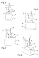
- reference numeral 1 is an appliance usable to perform bending tests on tyre-changing machines.
- the appliance 1 can be fitted on a traditional tyre-changing machine A.
- the tyre-changing machine A shown in Figure 1 has a supporting base B, arranged resting on the ground, which supports a self-centering spindle C for gripping and rotating the rim of a wheel.
- the machine A also comprises an upright D that extends vertically from the base B and which supports a tool-holder arm E, movable in height and horizontally due to the action of suitable actuator means, not shown.
- the lower extremity of the tool-holder arm E is suitable for supporting a tool, not shown in Figure 1 , suitable for removing and/or mounting the tyre from and onto the rim.
- the appliance 1 comprises:
- the appliance 1 allows to simulate the stresses to which the tyre-changing machine A normally undergoes, in particular the tool-holder arm E, during the removal/mounting jobs of a tyre from/onto a rim of a wheel and allows to check the bending response of the whole machine structure.
- FIGS 5, 6 and 7 are schematically illustrated the tangential force Ft, the axial force Fv and the radial force Fr respectively, applicable to the tyre-changing machine A by means of the appliance 1.
- the actuator means 5 are suitable for simultaneously applying the tangential force Ft, the axial force Fv and the radial force Fr to the tool-holder arm E.
- the actuator means 5 comprise:
- the first actuator 7, the second actuator 8 and the third actuator 9 are made up of respective fluid-operated linear actuators.
- the second attachment means 4 can be made by means of a suitable tubular element which can be fitted on a portion of the tool-holder arm, having appropriate flanges associated with respective mobile stems of the first, second and third actuators 7, 8 and 9.
- each of the forces is generated by several actuators suitably connected to one another.
- the bending measuring means 6 comprise:
- the first measuring device 10, the second measuring device 11 and the third measuring device 12 are made up of respective digital comparators for the measurement of the linear shift.
- the first measuring device 10, the second measuring device 11 and the third measuring device 12 are fixed to the first actuator 7, to the second actuator 8 and to the third actuator 9 respectively and have corresponding feelers engaged in correspondence of respective portions of the second attachment means 4.
- the realization of bending measuring means 6 by means of different measuring devices arranged differently cannot be ruled out.
- the supporting structure 2 is made up of a supporting plate and the first attachment means 3 are made up of two pairs of profiled elements of the plate itself, substantially opposite to one another and suitable for housing in contact respective stop elements F of the spindle C.
- the stop elements F are made up of two pairs of movable jaws, suitable for engaging in correspondence of the profiled elements 3 for locking the plate 2.
- the two pairs of profiled elements 3 can be made in correspondence of opposite sections of the outer edge of the plate itself and/or within slots formed on the plate itself.
- the attachment means 3 of the appliance 1 may comprise a through hole, made in correspondence of a substantially central portion of the plate 2, and suitable for allowing the insertion of a conventional pin with centering cone, for locking the plate itself on the spindle C.
- the appliance 1 comprises control means 13 for activating/deactivating the actuator means 5.
- control means 13 comprise a first switch 14 suitable for activating/deactivating the first actuator 7, a second switch 15 suitable for activating/deactivating the second actuator 8 and a third switch 16 suitable for activating/deactivating the third actuator 9.
- the control means 13 also comprise at least a general switch 17 suitable for activating/deactivating simultaneously the first actuator 7, the second actuator 8 and the third actuator 9.
- control means 13 comprise adjustment means suitable for adjusting the intensity of the tangential force Ft, the axial force Fv and the radial force Fr.
- the adjustment means are made up of an adjustment knob 18 and an indicator 19 of the intensity of the force applied.
- the method comprises the following steps:
- the method involves applying the tangential force Ft, the axial force Fv and the radial force Fr simultaneously on the tool-holder arm E.
- the method according to the invention may also comprise adjusting the intensity of the tangential force Ft, of the axial force Fv and/or of the radial force Fr, by means of the adjustment means 18.
- the appliance according to the invention allows to accurately check the bending response of the whole structure of a tyre-changing machine, as a result of the stresses which occur during the conventional removal/mounting jobs of a wheel tyre.
Applications Claiming Priority (1)
| Application Number | Priority Date | Filing Date | Title |
|---|---|---|---|
| IT000136A ITMO20130136A1 (it) | 2013-05-17 | 2013-05-17 | Apparecchiatura e metodo per prove di flessione su macchine smontagomme o simili |
Publications (2)
| Publication Number | Publication Date |
|---|---|
| EP2803970A1 true EP2803970A1 (de) | 2014-11-19 |
| EP2803970B1 EP2803970B1 (de) | 2015-12-02 |
Family
ID=49486308
Family Applications (1)
| Application Number | Title | Priority Date | Filing Date |
|---|---|---|---|
| EP14168442.3A Active EP2803970B1 (de) | 2013-05-17 | 2014-05-15 | Vorrichtung und Verfahren zum Durchführen von Biegetests an Reifenwechselmaschinen |
Country Status (2)
| Country | Link |
|---|---|
| EP (1) | EP2803970B1 (de) |
| IT (1) | ITMO20130136A1 (de) |
Citations (2)
| Publication number | Priority date | Publication date | Assignee | Title |
|---|---|---|---|---|
| ITMI951050A1 (it) * | 1995-05-23 | 1996-11-23 | Vamag Srl | Attrezzo atto alla rilevazione degli sforzi agenti su un pneumatico nonche' di quelli prodotti per reazione su una |
| EP2319715A1 (de) * | 2009-11-05 | 2011-05-11 | CORGHI S.p.A. | Vorrichtung und Verfahren zur Montage und Entfernung von Reifen an bzw. von den jeweiligen Radfelgen |
-
2013
- 2013-05-17 IT IT000136A patent/ITMO20130136A1/it unknown
-
2014
- 2014-05-15 EP EP14168442.3A patent/EP2803970B1/de active Active
Patent Citations (2)
| Publication number | Priority date | Publication date | Assignee | Title |
|---|---|---|---|---|
| ITMI951050A1 (it) * | 1995-05-23 | 1996-11-23 | Vamag Srl | Attrezzo atto alla rilevazione degli sforzi agenti su un pneumatico nonche' di quelli prodotti per reazione su una |
| EP2319715A1 (de) * | 2009-11-05 | 2011-05-11 | CORGHI S.p.A. | Vorrichtung und Verfahren zur Montage und Entfernung von Reifen an bzw. von den jeweiligen Radfelgen |
Also Published As
| Publication number | Publication date |
|---|---|
| EP2803970B1 (de) | 2015-12-02 |
| ITMO20130136A1 (it) | 2014-11-18 |
Similar Documents
| Publication | Publication Date | Title |
|---|---|---|
| US10071607B2 (en) | Apparatus and method for mounting and removing tyres on and from respective wheel rims | |
| US8291958B2 (en) | Machine for fitting and removing the tires of vehicles | |
| US9283820B1 (en) | Wheel assembly service machine with back cone center clamp mechanism | |
| WO2012052970A1 (en) | A tyre demounting machine | |
| EP2905154B1 (de) | Reifenwechselmaschine | |
| EP2551131B1 (de) | Vorrichtung zum Spannen von Radfelgen für Fahrzeuge auf Aufnahmen von Reifenwechselmaschinen | |
| EP1897709A1 (de) | Maschine zum Anbringen und Abnehmen von Fahrzeugreifen | |
| US9114675B2 (en) | Bead breaking unit for tyre changing machines | |
| EP2253487B1 (de) | Werkzeug für eine Reifenabziehmaschine | |
| EP2995478A2 (de) | Maschine zum abnehmen und anbringen von radreifen für fahrzeuge | |
| JP5401081B2 (ja) | 車両用ホイールタイヤの取り付け・取り外し装置 | |
| JP4271564B2 (ja) | タイヤを取付ける方法および装置、およびタイヤを分析する方法 | |
| EP2803970B1 (de) | Vorrichtung und Verfahren zum Durchführen von Biegetests an Reifenwechselmaschinen | |
| EP2995476B1 (de) | Betriebskopf zum entfernen und anbringen von radreifen für fahrzeuge | |
| EP2756969B1 (de) | Maschine zum Entfernen/ Aufbringen eines Reifens von/ auf eine(r) Felge eines Fahrzeugs | |
| EP3608129A1 (de) | Methode um reifen von fahrzeugrädern zu demontieren | |
| US20150224834A1 (en) | Tyre-changing machine | |
| US20110030904A1 (en) | Unit for beading tires in tire changing machines or the like | |
| WO2022249018A1 (en) | Device for fitting/removing tires | |
| EP3882054A1 (de) | Werkzeug für eine reifenwechselmaschine | |
| CS215369B1 (cs) | Zařízeni na odtlaěování a převlčkáirřpatek plášťů pneumatik při demontáži |
Legal Events
| Date | Code | Title | Description |
|---|---|---|---|
| PUAI | Public reference made under article 153(3) epc to a published international application that has entered the european phase |
Free format text: ORIGINAL CODE: 0009012 |
|
| 17P | Request for examination filed |
Effective date: 20140515 |
|
| AK | Designated contracting states |
Kind code of ref document: A1 Designated state(s): AL AT BE BG CH CY CZ DE DK EE ES FI FR GB GR HR HU IE IS IT LI LT LU LV MC MK MT NL NO PL PT RO RS SE SI SK SM TR |
|
| AX | Request for extension of the european patent |
Extension state: BA ME |
|
| R17P | Request for examination filed (corrected) |
Effective date: 20150505 |
|
| RBV | Designated contracting states (corrected) |
Designated state(s): AL AT BE BG CH CY CZ DE DK EE ES FI FR GB GR HR HU IE IS IT LI LT LU LV MC MK MT NL NO PL PT RO RS SE SI SK SM TR |
|
| GRAP | Despatch of communication of intention to grant a patent |
Free format text: ORIGINAL CODE: EPIDOSNIGR1 |
|
| RIC1 | Information provided on ipc code assigned before grant |
Ipc: B60C 25/05 20060101ALI20150526BHEP Ipc: G01N 3/20 20060101AFI20150526BHEP |
|
| INTG | Intention to grant announced |
Effective date: 20150623 |
|
| GRAS | Grant fee paid |
Free format text: ORIGINAL CODE: EPIDOSNIGR3 |
|
| GRAA | (expected) grant |
Free format text: ORIGINAL CODE: 0009210 |
|
| AK | Designated contracting states |
Kind code of ref document: B1 Designated state(s): AL AT BE BG CH CY CZ DE DK EE ES FI FR GB GR HR HU IE IS IT LI LT LU LV MC MK MT NL NO PL PT RO RS SE SI SK SM TR |
|
| REG | Reference to a national code |
Ref country code: GB Ref legal event code: FG4D |
|
| REG | Reference to a national code |
Ref country code: AT Ref legal event code: REF Ref document number: 763835 Country of ref document: AT Kind code of ref document: T Effective date: 20151215 Ref country code: CH Ref legal event code: EP |
|
| REG | Reference to a national code |
Ref country code: IE Ref legal event code: FG4D |
|
| REG | Reference to a national code |
Ref country code: DE Ref legal event code: R096 Ref document number: 602014000507 Country of ref document: DE |
|
| REG | Reference to a national code |
Ref country code: NL Ref legal event code: MP Effective date: 20160302 |
|
| REG | Reference to a national code |
Ref country code: LT Ref legal event code: MG4D |
|
| REG | Reference to a national code |
Ref country code: AT Ref legal event code: MK05 Ref document number: 763835 Country of ref document: AT Kind code of ref document: T Effective date: 20151202 |
|
| PG25 | Lapsed in a contracting state [announced via postgrant information from national office to epo] |
Ref country code: NO Free format text: LAPSE BECAUSE OF FAILURE TO SUBMIT A TRANSLATION OF THE DESCRIPTION OR TO PAY THE FEE WITHIN THE PRESCRIBED TIME-LIMIT Effective date: 20160302 Ref country code: LT Free format text: LAPSE BECAUSE OF FAILURE TO SUBMIT A TRANSLATION OF THE DESCRIPTION OR TO PAY THE FEE WITHIN THE PRESCRIBED TIME-LIMIT Effective date: 20151202 Ref country code: ES Free format text: LAPSE BECAUSE OF FAILURE TO SUBMIT A TRANSLATION OF THE DESCRIPTION OR TO PAY THE FEE WITHIN THE PRESCRIBED TIME-LIMIT Effective date: 20151202 |
|
| REG | Reference to a national code |
Ref country code: FR Ref legal event code: PLFP Year of fee payment: 3 |
|
| PG25 | Lapsed in a contracting state [announced via postgrant information from national office to epo] |
Ref country code: PL Free format text: LAPSE BECAUSE OF FAILURE TO SUBMIT A TRANSLATION OF THE DESCRIPTION OR TO PAY THE FEE WITHIN THE PRESCRIBED TIME-LIMIT Effective date: 20151202 Ref country code: FI Free format text: LAPSE BECAUSE OF FAILURE TO SUBMIT A TRANSLATION OF THE DESCRIPTION OR TO PAY THE FEE WITHIN THE PRESCRIBED TIME-LIMIT Effective date: 20151202 Ref country code: RS Free format text: LAPSE BECAUSE OF FAILURE TO SUBMIT A TRANSLATION OF THE DESCRIPTION OR TO PAY THE FEE WITHIN THE PRESCRIBED TIME-LIMIT Effective date: 20151202 Ref country code: AT Free format text: LAPSE BECAUSE OF FAILURE TO SUBMIT A TRANSLATION OF THE DESCRIPTION OR TO PAY THE FEE WITHIN THE PRESCRIBED TIME-LIMIT Effective date: 20151202 Ref country code: NL Free format text: LAPSE BECAUSE OF FAILURE TO SUBMIT A TRANSLATION OF THE DESCRIPTION OR TO PAY THE FEE WITHIN THE PRESCRIBED TIME-LIMIT Effective date: 20151202 Ref country code: GR Free format text: LAPSE BECAUSE OF FAILURE TO SUBMIT A TRANSLATION OF THE DESCRIPTION OR TO PAY THE FEE WITHIN THE PRESCRIBED TIME-LIMIT Effective date: 20160303 Ref country code: LV Free format text: LAPSE BECAUSE OF FAILURE TO SUBMIT A TRANSLATION OF THE DESCRIPTION OR TO PAY THE FEE WITHIN THE PRESCRIBED TIME-LIMIT Effective date: 20151202 Ref country code: SE Free format text: LAPSE BECAUSE OF FAILURE TO SUBMIT A TRANSLATION OF THE DESCRIPTION OR TO PAY THE FEE WITHIN THE PRESCRIBED TIME-LIMIT Effective date: 20151202 |
|
| PG25 | Lapsed in a contracting state [announced via postgrant information from national office to epo] |
Ref country code: IS Free format text: LAPSE BECAUSE OF FAILURE TO SUBMIT A TRANSLATION OF THE DESCRIPTION OR TO PAY THE FEE WITHIN THE PRESCRIBED TIME-LIMIT Effective date: 20151202 |
|
| PG25 | Lapsed in a contracting state [announced via postgrant information from national office to epo] |
Ref country code: CZ Free format text: LAPSE BECAUSE OF FAILURE TO SUBMIT A TRANSLATION OF THE DESCRIPTION OR TO PAY THE FEE WITHIN THE PRESCRIBED TIME-LIMIT Effective date: 20151202 |
|
| PG25 | Lapsed in a contracting state [announced via postgrant information from national office to epo] |
Ref country code: EE Free format text: LAPSE BECAUSE OF FAILURE TO SUBMIT A TRANSLATION OF THE DESCRIPTION OR TO PAY THE FEE WITHIN THE PRESCRIBED TIME-LIMIT Effective date: 20151202 Ref country code: IS Free format text: LAPSE BECAUSE OF FAILURE TO SUBMIT A TRANSLATION OF THE DESCRIPTION OR TO PAY THE FEE WITHIN THE PRESCRIBED TIME-LIMIT Effective date: 20160402 Ref country code: SM Free format text: LAPSE BECAUSE OF FAILURE TO SUBMIT A TRANSLATION OF THE DESCRIPTION OR TO PAY THE FEE WITHIN THE PRESCRIBED TIME-LIMIT Effective date: 20151202 Ref country code: BE Free format text: LAPSE BECAUSE OF NON-PAYMENT OF DUE FEES Effective date: 20160531 Ref country code: SK Free format text: LAPSE BECAUSE OF FAILURE TO SUBMIT A TRANSLATION OF THE DESCRIPTION OR TO PAY THE FEE WITHIN THE PRESCRIBED TIME-LIMIT Effective date: 20151202 Ref country code: RO Free format text: LAPSE BECAUSE OF FAILURE TO SUBMIT A TRANSLATION OF THE DESCRIPTION OR TO PAY THE FEE WITHIN THE PRESCRIBED TIME-LIMIT Effective date: 20151202 Ref country code: PT Free format text: LAPSE BECAUSE OF FAILURE TO SUBMIT A TRANSLATION OF THE DESCRIPTION OR TO PAY THE FEE WITHIN THE PRESCRIBED TIME-LIMIT Effective date: 20160404 |
|
| REG | Reference to a national code |
Ref country code: DE Ref legal event code: R097 Ref document number: 602014000507 Country of ref document: DE |
|
| PLBE | No opposition filed within time limit |
Free format text: ORIGINAL CODE: 0009261 |
|
| STAA | Information on the status of an ep patent application or granted ep patent |
Free format text: STATUS: NO OPPOSITION FILED WITHIN TIME LIMIT |
|
| PG25 | Lapsed in a contracting state [announced via postgrant information from national office to epo] |
Ref country code: DK Free format text: LAPSE BECAUSE OF FAILURE TO SUBMIT A TRANSLATION OF THE DESCRIPTION OR TO PAY THE FEE WITHIN THE PRESCRIBED TIME-LIMIT Effective date: 20151202 |
|
| 26N | No opposition filed |
Effective date: 20160905 |
|
| PG25 | Lapsed in a contracting state [announced via postgrant information from national office to epo] |
Ref country code: SI Free format text: LAPSE BECAUSE OF FAILURE TO SUBMIT A TRANSLATION OF THE DESCRIPTION OR TO PAY THE FEE WITHIN THE PRESCRIBED TIME-LIMIT Effective date: 20151202 |
|
| PG25 | Lapsed in a contracting state [announced via postgrant information from national office to epo] |
Ref country code: BE Free format text: LAPSE BECAUSE OF FAILURE TO SUBMIT A TRANSLATION OF THE DESCRIPTION OR TO PAY THE FEE WITHIN THE PRESCRIBED TIME-LIMIT Effective date: 20151202 Ref country code: LU Free format text: LAPSE BECAUSE OF FAILURE TO SUBMIT A TRANSLATION OF THE DESCRIPTION OR TO PAY THE FEE WITHIN THE PRESCRIBED TIME-LIMIT Effective date: 20160515 |
|
| REG | Reference to a national code |
Ref country code: IE Ref legal event code: MM4A |
|
| REG | Reference to a national code |
Ref country code: FR Ref legal event code: PLFP Year of fee payment: 4 |
|
| PG25 | Lapsed in a contracting state [announced via postgrant information from national office to epo] |
Ref country code: IE Free format text: LAPSE BECAUSE OF NON-PAYMENT OF DUE FEES Effective date: 20160515 |
|
| REG | Reference to a national code |
Ref country code: CH Ref legal event code: PL |
|
| PG25 | Lapsed in a contracting state [announced via postgrant information from national office to epo] |
Ref country code: LI Free format text: LAPSE BECAUSE OF NON-PAYMENT OF DUE FEES Effective date: 20170531 Ref country code: CH Free format text: LAPSE BECAUSE OF NON-PAYMENT OF DUE FEES Effective date: 20170531 |
|
| REG | Reference to a national code |
Ref country code: FR Ref legal event code: PLFP Year of fee payment: 5 |
|
| PG25 | Lapsed in a contracting state [announced via postgrant information from national office to epo] |
Ref country code: HU Free format text: LAPSE BECAUSE OF FAILURE TO SUBMIT A TRANSLATION OF THE DESCRIPTION OR TO PAY THE FEE WITHIN THE PRESCRIBED TIME-LIMIT; INVALID AB INITIO Effective date: 20140515 |
|
| PG25 | Lapsed in a contracting state [announced via postgrant information from national office to epo] |
Ref country code: MT Free format text: LAPSE BECAUSE OF NON-PAYMENT OF DUE FEES Effective date: 20160531 Ref country code: MK Free format text: LAPSE BECAUSE OF FAILURE TO SUBMIT A TRANSLATION OF THE DESCRIPTION OR TO PAY THE FEE WITHIN THE PRESCRIBED TIME-LIMIT Effective date: 20151202 Ref country code: HR Free format text: LAPSE BECAUSE OF FAILURE TO SUBMIT A TRANSLATION OF THE DESCRIPTION OR TO PAY THE FEE WITHIN THE PRESCRIBED TIME-LIMIT Effective date: 20151202 Ref country code: CY Free format text: LAPSE BECAUSE OF FAILURE TO SUBMIT A TRANSLATION OF THE DESCRIPTION OR TO PAY THE FEE WITHIN THE PRESCRIBED TIME-LIMIT Effective date: 20151202 Ref country code: MC Free format text: LAPSE BECAUSE OF FAILURE TO SUBMIT A TRANSLATION OF THE DESCRIPTION OR TO PAY THE FEE WITHIN THE PRESCRIBED TIME-LIMIT Effective date: 20151202 |
|
| PG25 | Lapsed in a contracting state [announced via postgrant information from national office to epo] |
Ref country code: BG Free format text: LAPSE BECAUSE OF FAILURE TO SUBMIT A TRANSLATION OF THE DESCRIPTION OR TO PAY THE FEE WITHIN THE PRESCRIBED TIME-LIMIT Effective date: 20151202 |
|
| PG25 | Lapsed in a contracting state [announced via postgrant information from national office to epo] |
Ref country code: AL Free format text: LAPSE BECAUSE OF FAILURE TO SUBMIT A TRANSLATION OF THE DESCRIPTION OR TO PAY THE FEE WITHIN THE PRESCRIBED TIME-LIMIT Effective date: 20151202 Ref country code: TR Free format text: LAPSE BECAUSE OF FAILURE TO SUBMIT A TRANSLATION OF THE DESCRIPTION OR TO PAY THE FEE WITHIN THE PRESCRIBED TIME-LIMIT Effective date: 20151202 |
|
| GBPC | Gb: european patent ceased through non-payment of renewal fee |
Effective date: 20180515 |
|
| PG25 | Lapsed in a contracting state [announced via postgrant information from national office to epo] |
Ref country code: GB Free format text: LAPSE BECAUSE OF NON-PAYMENT OF DUE FEES Effective date: 20180515 |
|
| PGFP | Annual fee paid to national office [announced via postgrant information from national office to epo] |
Ref country code: IT Payment date: 20230525 Year of fee payment: 10 Ref country code: FR Payment date: 20230525 Year of fee payment: 10 Ref country code: DE Payment date: 20230530 Year of fee payment: 10 |