EP2803943A1 - Procédé de transmission de signaux de mesure dans un centre de traitement doté d'au moins deux broches; palpeur de mesure et récepteur pour le procédé - Google Patents
Procédé de transmission de signaux de mesure dans un centre de traitement doté d'au moins deux broches; palpeur de mesure et récepteur pour le procédé Download PDFInfo
- Publication number
- EP2803943A1 EP2803943A1 EP14001583.5A EP14001583A EP2803943A1 EP 2803943 A1 EP2803943 A1 EP 2803943A1 EP 14001583 A EP14001583 A EP 14001583A EP 2803943 A1 EP2803943 A1 EP 2803943A1
- Authority
- EP
- European Patent Office
- Prior art keywords
- mtb
- mta
- probe
- dta1
- dtbn
- Prior art date
- Legal status (The legal status is an assumption and is not a legal conclusion. Google has not performed a legal analysis and makes no representation as to the accuracy of the status listed.)
- Granted
Links
- 239000000523 sample Substances 0.000 title claims abstract description 366
- 238000000034 method Methods 0.000 title claims abstract description 31
- 238000005259 measurement Methods 0.000 title claims description 45
- 238000003754 machining Methods 0.000 title description 9
- 230000005540 biological transmission Effects 0.000 claims abstract description 83
- 230000004913 activation Effects 0.000 claims description 12
- 230000003750 conditioning effect Effects 0.000 claims description 9
- 238000012545 processing Methods 0.000 claims description 8
- 230000007704 transition Effects 0.000 claims description 8
- 230000002123 temporal effect Effects 0.000 claims description 4
- 238000004891 communication Methods 0.000 claims description 3
- 238000001514 detection method Methods 0.000 claims description 2
- 238000011156 evaluation Methods 0.000 claims description 2
- 230000002045 lasting effect Effects 0.000 claims 1
- 230000003287 optical effect Effects 0.000 description 9
- 238000010586 diagram Methods 0.000 description 5
- 238000013459 approach Methods 0.000 description 4
- 230000008569 process Effects 0.000 description 4
- 230000008859 change Effects 0.000 description 3
- UOTQEHLQKASWQO-UHFFFAOYSA-N 2-(5-sulfanylidene-2h-tetrazol-1-yl)acetic acid Chemical compound OC(=O)CN1N=NN=C1S UOTQEHLQKASWQO-UHFFFAOYSA-N 0.000 description 2
- 230000006870 function Effects 0.000 description 2
- 238000000926 separation method Methods 0.000 description 2
- 238000012546 transfer Methods 0.000 description 2
- VZDUQPHKUBZMLW-UHFFFAOYSA-N 1-(benzenesulfonyl)-4-chloro-2-nitrobenzene Chemical compound [O-][N+](=O)C1=CC(Cl)=CC=C1S(=O)(=O)C1=CC=CC=C1 VZDUQPHKUBZMLW-UHFFFAOYSA-N 0.000 description 1
- 101100004714 Schizosaccharomyces pombe (strain 972 / ATCC 24843) btb1 gene Proteins 0.000 description 1
- 101100004715 Schizosaccharomyces pombe (strain 972 / ATCC 24843) btb2 gene Proteins 0.000 description 1
- 238000004590 computer program Methods 0.000 description 1
- 230000003111 delayed effect Effects 0.000 description 1
- 230000000694 effects Effects 0.000 description 1
- 238000005516 engineering process Methods 0.000 description 1
- 230000012447 hatching Effects 0.000 description 1
- 230000001939 inductive effect Effects 0.000 description 1
- 238000009434 installation Methods 0.000 description 1
- 238000013208 measuring procedure Methods 0.000 description 1
- 239000002184 metal Substances 0.000 description 1
- 239000004033 plastic Substances 0.000 description 1
- 230000000284 resting effect Effects 0.000 description 1
- 230000008054 signal transmission Effects 0.000 description 1
- 230000001360 synchronised effect Effects 0.000 description 1
- 239000002023 wood Substances 0.000 description 1
Images


Classifications
-
- G—PHYSICS
- G01—MEASURING; TESTING
- G01B—MEASURING LENGTH, THICKNESS OR SIMILAR LINEAR DIMENSIONS; MEASURING ANGLES; MEASURING AREAS; MEASURING IRREGULARITIES OF SURFACES OR CONTOURS
- G01B5/00—Measuring arrangements characterised by the use of mechanical techniques
- G01B5/004—Measuring arrangements characterised by the use of mechanical techniques for measuring coordinates of points
- G01B5/008—Measuring arrangements characterised by the use of mechanical techniques for measuring coordinates of points using coordinate measuring machines
-
- G—PHYSICS
- G01—MEASURING; TESTING
- G01B—MEASURING LENGTH, THICKNESS OR SIMILAR LINEAR DIMENSIONS; MEASURING ANGLES; MEASURING AREAS; MEASURING IRREGULARITIES OF SURFACES OR CONTOURS
- G01B21/00—Measuring arrangements or details thereof, where the measuring technique is not covered by the other groups of this subclass, unspecified or not relevant
- G01B21/02—Measuring arrangements or details thereof, where the measuring technique is not covered by the other groups of this subclass, unspecified or not relevant for measuring length, width, or thickness
- G01B21/04—Measuring arrangements or details thereof, where the measuring technique is not covered by the other groups of this subclass, unspecified or not relevant for measuring length, width, or thickness by measuring coordinates of points
- G01B21/047—Accessories, e.g. for positioning, for tool-setting, for measuring probes
-
- H—ELECTRICITY
- H04—ELECTRIC COMMUNICATION TECHNIQUE
- H04Q—SELECTING
- H04Q9/00—Arrangements in telecontrol or telemetry systems for selectively calling a substation from a main station, in which substation desired apparatus is selected for applying a control signal thereto or for obtaining measured values therefrom
-
- G—PHYSICS
- G01—MEASURING; TESTING
- G01B—MEASURING LENGTH, THICKNESS OR SIMILAR LINEAR DIMENSIONS; MEASURING ANGLES; MEASURING AREAS; MEASURING IRREGULARITIES OF SURFACES OR CONTOURS
- G01B2210/00—Aspects not specifically covered by any group under G01B, e.g. of wheel alignment, caliper-like sensors
- G01B2210/58—Wireless transmission of information between a sensor or probe and a control or evaluation unit
Definitions
- a machining center is a machine tool equipped for automated operation with a CNC control for the complete machining of (metal, wood or plastic) workpieces.
- a tool or a workpiece can be mounted on each of the two spindles; the spindles may be fixedly positioned or, for example, moved and driven in three orthogonal directions X, Y, Z within a working space of the machining center.
- Machining centers usually have an automatic tool and workpiece changer, which - initiated by the CNC control - can switch a probe into the respective spindle and change it in order to also measure the workpiece machined with this spindle.
- the tool can be moved by the machine tool into a measuring space, an area specified for the measurement, a contact or contactless operating button.
- the non-contact button detects the proximity of a surface, for example, with a capacitive, inductive or optical device.
- the touching button detects a surface when in contact with it.
- contact and contactless probes pass corresponding measurement data to a numerical machine controller, which may include a computer program. Together with machine position information from the controller, the probe measurement data allows the numerical controller, such as a CNC controller, to obtain an accurate picture of the dimensions of the tool or workpiece.
- the DE 102 62 188 A1 relates to a multidirectional probe with a housing in which an annular support bearing is formed, which defines an X, Y bearing plane and a normal Z axis of the probe to normal.
- a Tastrich technique is centrally located to receive a stylus.
- a transmission member is slidably guided in the housing along the central axis Z in order to implement any deflections of the support body from its rest position into rectilinear movements.
- a sensor converts the movements of the transmission element into measuring signals.
- the transmission of the measurement signals from a probe to a stationary receiving part is wireless either by optical signals or by radio signals.
- the probes in a machining center come from the same manufacturer and work identically. If the two measuring probes use the same transmission channel synchronously, the simultaneous operation of the two measuring probes leads to unwanted signal collisions.
- Optical systems use light signals of different wavelengths for the two probes and radio systems use different carrier frequencies.
- a disadvantage of these systems is that a separate receiver is required for each transmission channel, which increases the costs for the entire system.
- a channel separation between the two available transmission channels is in practice great difficulties in optical systems, since it can come to mutual interference between the two transmission channels.
- Optical probes are usually activated by a flash of light emitted into the workspace of the machining center where the two probes are located. Thus, these two probes are also activated at the same time. A targeted successive activation of the two probes by directed light flashes is practically impossible. If the two flashes of light overlap, there is no guarantee that both probes will be activated. Even if optical systems can be selectively activated with a light flash signal assigned to the respective measuring probe, it is then also necessary to measure sequentially with the two measuring probes. Since the measuring procedure has to be carried out twice, the entire measuring time is considerably extended.
- the two probes can also work with different modulation frequencies.
- the disadvantage of this approach is that while two receiving parts are needed.
- the demodulator for the lower modulation frequency is very easily disturbed by the higher modulation frequency.
- a probing process ie a transition of the probe from its non-deflected position in its deflected position, as soon as possible by means of a status message to the receiving part and from there to the machine control to be transmitted.
- the status messages should always be transmitted to the machine control with as much as possible the same transmission time. From one measurement to the next, different transmission times of the status messages from a probe to the receiver lead to a falsification of the measurement results. Therefore, it is not possible for the two probes to repeat the transmission of their respective status messages to the receiving part until the status messages are correctly received by the receiving part at random.
- a wireless probe z. B. the probe TC60 of the applicant can be used.
- Such a probe can transmit the measuring signals in a very time-efficient and reliable way in the automatic determination of workpiece position, workpiece position and workpiece dimensions in machining centers.
- each individual bit of the radio-transmitted measuring signal is spread over the entire frequency band, and not, as usual with touch probes of other manufacturers, the measurement signal in the channel hopping or fixed channel assignment transmitted. This is the transmission particularly insensitive to interference.
- the synchronous transmission of measuring signals is not provided with this technique either.
- the method presented here is used to transmit data telegrams at least two, each to be included in a spindle of a machining center probe.
- the data telegrams are transmitted by the respective measuring probe via a common transmission channel for reception by the receiving part.
- two or more data telegrams are transmitted, each of which comprises a characteristic of the respective probe information, a characteristic of the particular probe identifier, and an ordinal number of the respective data telegram with which the characteristic information is sent for each probe.
- a substantially constant cycle time elapses.
- the pause time between the data telegrams is different for each of the respective probes depending on a number of communicating with the receiving part probe in the machining center, the cycle time of each of the probes between two of their data telegrams with the same ordinal number and / or a transmission time for a single one of the data telegrams ,
- the thus organized transmission of the data telegrams ensures that for each of the probes at least one of its data telegrams is not affected by a data telegram of other probes.
- this receiving part can communicate at least one of the data telegrams of all in the processing center with this receiving part via a single transmission channel Receive and evaluate the probe separately from the other data telegrams. For each measurement of a probe two or more data telegrams with different ordinal numbers are sent.
- the approach presented here allows parallel operation and thus (at least nearly) simultaneous measurement with two or more probes communicating with a single, stationary receiver over a single transmission channel.
- an activation signal is sent to the respective measuring probes before the data telegrams are transmitted.
- the transmission of the data telegrams can be initiated by the respective probe.
- an evaluation of the data telegrams after their receipt by the receiving part, and outputting a characteristic of the respective measurement signal output signal can be provided by the receiving part to a numerical control of the machining center.
- each of the probes can be activated by means of a dedicated activation signal for the respective probe.
- each of the probes can be activated by means of a common activation signal for all, a single receiving part associated probe.
- the or each of the activation signals can be transmitted to the measuring probes either by the receiving part and / or by the numerical control of the machining center.
- the (status) information characteristic of the particular probe can be deflected according to a variant depending on the presence of one of two operating modes "normal operation” and “trigger operation", the states (i) “probe is in rest position", (ii) “probe "and / or the states (iii)” Probe probe battery is good “(iv)” Probe probe battery is (nearly) empty “, and / or” Switching point 1 "," Switching point 2 "" Switching point n " , include.
- the probes can emit their data telegrams in predetermined time intervals to the receiving part according to a variant after their activation.
- the receiving part monitored according to a variant in particular in the operating mode "normal operation" of the probe, the receiving part, whether a communication with the probes continuously exists, and / or if the state "Battery of the probe is good” in "battery of the probe is empty” for one of Probe has changed. If this is the case, it can be provided according to a variant that a characteristic warning signal for this is emitted by the receiving part.
- the cycle time between two (successive) of its data telegrams is at least approximately identical to the same ordinal number, ie for different measurements.
- the transmission time of the data telegrams is at least approximately identical for all data telegrams of all measuring probes.
- the number of data telegrams may change according to a variant, for example: In normal operation, for example, two data telegrams are sent out, for example, three data telegrams are transmitted in trigger operation.
- the cycle times of all probes and the pause time between the data telegrams of each of the probes are preferably to be determined so that the sum of the transmission times of all first data telegrams of the other probes is less than or equal to the pause time between the data telegrams of the respective probe.
- the cycle times of all probes can be set to different lengths in both "normal operation” and “trigger operation” operating modes.
- this security phase can be about 1 to 3% of the transmission time of a data telegram, depending on the total transmission time for a single one of the data telegrams, for example. This further reduces the risk of collision of the data telegrams.
- the cycle times and the pause times between two of their respective data telegrams with the same ordinal number for each of the probes are known according to a variant.
- each characteristic of each probe can be set, each of the probes, the cycle times of all probes can be entered or selected, and each of the probes, the pause times for consecutive data telegrams of all probes can be entered or selected ,
- a trigger event occurs which, for example, results in reaching the "switching point 1", the “switching point 2" ... or the “switching point n” or “the probe is at rest", "Probe is deflected” may include.
- This trigger event causes the respective probe to change from “normal mode” to "trigger mode”;
- the receiving part of this trigger event should be informed as quickly and safely as possible, so that the receiving part of this trigger event with a constant and known delay time can be sent to the CNC control of the machining center.
- a switching signal can then be generated by the receiving part according to a variant in the "trigger mode", which can be forwarded to the CNC control and used there together with the - known there - spindle feed to determine a result of the workpiece measurement.
- Trigger mode is essential according to a variant that for high accuracy in the workpiece measurement, the transition of the probe from its undeflected position in its deflected position - or vice versa - as fast as a data telegram reaches the receiver, where it is evaluated, and is transferred from there to the machine control.
- the one characteristic for the particular probe information ie the state transition of the probe
- a characteristic of the particular probe identifier ie for example, which number / address the probe has
- an ordinal number of the respective data telegram with which the characteristic information for the respective probe is sent.
- each probe transmits the data telegrams in triplicate, whereby in each case the ordinal number of the respective data telegram is increased by one. It is essential here according to a variant that each of the data telegrams is sent in a defined time frame, which is different for each probe. This temporal grid is set for all probes as a whole so that even with time offset and not within the cycle times predictable time of sending the individual data telegrams by other probe at least one of the three data telegrams each probe not temporally conflict with other and therefore arrive undisturbed at the receiving part can.
- the temporal sequence of the data telegrams of each individual probe and the pauses between them, as well as the time sequences of the data telegrams of all probes can be designed according to a variant such that in a defined period, so for example a cycle time, always at least one data telegram each probe of data telegrams other probe is transmitted undisturbed to the receiving part.
- a time sequence of 11 time slots is provided.
- Each of the 11 time slots is as long as the transmission time for a single one of the data telegrams plus, if necessary, a processing time for the processing of the data telegram on the part of the receiving part and / or the probe.
- one measuring probe in the 1st, 3rd and 9th time slots and the other measuring probe in the 1st, 5th and 9th time slots can transmit.
- one of the probes in the 1st, 3rd and 5th timeslots and the other probe in the 1st, 5th and 11th time slots can transmit.
- the time sequence of eleven time slots begins for each of the probes with the transmission of its first data telegram.
- the first probe starts the measurement cycle, it sends in the 1st, 3rd, and 5th time slots. If the second probe starts exactly one time slot later, its first data telegram falls exactly between the 1st and 3rd timeslot of the first probe. Thus, the two data telegrams of both probes can be evaluated immediately and without delay from the receiving part and forwarded.
- This distribution of the three data telegrams on the eleven time slots ensures that even with a time-offset transmission of the respective three data telegrams by the two probes at least one data telegram each probe does not collide with other data telegrams of the other probe time.
- the receiving part can be evaluated in a variant by the receiving part based on the ordinal number of the data telegram, whether the first, the second, or the third data telegram was received undisturbed by a probe. Based on this, in a variant by the receiving part prior to the retransmission of the characteristic information from the data telegram corresponding delay times are met to keep the time between a probing on the workpiece and output of the switching signal by the receiving part always at least approximately constant.
- the respective measuring probes and the receiving part can communicate with one another via a common transmission channel, a free radio link, or a free light path-bound common transmission channel.
- each probe is adapted to be recorded in each case in a spindle of the machining center.
- Each probe has a housing in which a support bearing is formed, which defines an X, Y bearing plane and a normal central axis Z of the probe.
- a Taststart technique is centrally located to receive a stylus and a transmission member is slidably guided in the housing along the central axis Z in order to implement any deflections of the support body from its rest position into rectilinear movements.
- a sensor converts the movements of the transmission element into measurement signals, which are processed in a probe-side signal processing unit for transmission to a receiving part.
- the signal processing unit is set up and programmed to transmit data telegrams via a common transmission channel assigned to all the receiving part for reception by the receiving part according to the method described above.
- a receiving part is also presented here for the purpose of receiving measuring signals of at least two measuring probes, each of which is to be recorded in a spindle of a machining center, obtained in measurements taken jointly.
- the receiving part is set up to determine whether the first, the second, or the third data telegram has been received by a probe, and corresponding delay times are maintained before retransmission of the characteristic information from the data telegram to the time between probing the workpiece and output the switching signal by the receiving part always keep at least approximately constant.
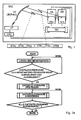
- Fig. 1 schematically illustrates a machining center BAZ with two spindles SA, SB, with which a workpiece WS is machined (milled, drilled, or the like.) In the operation of the machining center BAZ.
- the machining center BAZ has a CNC control.
- the two spindles SA, SB are here in three orthogonal directions X, Y, Z within a working space of the machining center relative to the workpiece WS movable and driven.
- two workpieces can be machined simultaneously, or on the workpiece WS both spindles SA, SB can work simultaneously as shown here.
- the measuring probes MTA, MTB shown here are touching; they each detect a (workpiece) surface upon contact with it. For each detected feature, the probes MTA, MTB output corresponding measurement signals.
- a probe of the applicant is for example in the DE 102 62 188 A1 discloses the contents of which is hereby incorporated by reference.
- the transmission of the measuring signals from each of the measuring probes MTA, MTB to a stationary receiving part ET takes place wirelessly either by optical signals or by radio signals.
- the procedure described below for signal transmission between the two measuring probes MTA, MTB and the stationary receiving part ET makes it possible for them to use the same transmission channel ÜK.
- the transmission channel ÜK is a light path, use the two probes MTAA, MTB light signals of the same wavelength and modulation schemes; If the transmission channel ÜK is a radio link, the two measuring probes MTA, MTB use the same carrier frequencies and modulation schemes. This makes it possible for both measuring probes MTAA, MTB to communicate with one and the same stationary receiving part ET via a transmission channel ÜK.
- Probe A Transmission channel ÜK ⁇ Receiver ET Probe B ⁇
- Fig. 2a shows a flowchart of a method variant presented here for generating and transmitting the data telegrams.
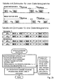
- Fig. 2b the expiration of the data telegram creation.
- Upper table ⁇ tA is the time between data telegram 1 and data telegram 2 from probe MTA S1 the data telegram 1 sent by the probe MTA S2 the data telegram 2, sent by probe MTA ⁇ t cycle the cycle time after which the next sequence of data telegrams is sent.
- Lower table ⁇ tB is the time between data telegram 1 and data telegram 2 from probe MTB S1 the data telegram 1 sent by the probe MTB S2 the data telegram 2 sent by the probe MTB ⁇ t cycle the cycle time after which the next sequence of data telegrams is sent.
- the transmission cycle ⁇ t cycle is the same for the probe MTA and for the probe MTB.
- the transmission distance between the 1st and the 2nd data telegram is different for the two probes MTA, MTB and is dimensioned so that even with the simultaneous transmission start of the two probes MTA, MTB always a data telegram is transmitted undisturbed.
- the time slots in which the data telegrams of a measuring probe and the pauses inserted between them are located are the table with a time pattern for three data telegrams.
- Each time slot 1 ... 11 has a transmission length of a data telegram plus, if necessary, a decoding time for the processing of the data telegram.
- RL denotes the rest position of the measuring probes MTA, MTB, and S1, S2, S3 are the three data telegrams.
- a measuring probe MTA in the 1st, 3rd and 9th time slots see upper line of variant 1
- the other measuring probe MTB in the 1st, 5 and 9th time slots see lower line of FIG Version 1
- the one probe sends MTA in the 1st, 3rd and 5th time slots (see upper line of variant 2), and the other probe in the 1st, 5th and 11th time slots (see the lower line of the Variant 2).
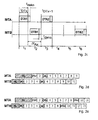
- timing diagram for the data transfer operation presented here is to be noted in a transition from a normal operation in a trigger mode that a telegram in the rest position RL at any time before a data message DT1 can occur, that is unsynchronized to the data message DT1 occurs. Therefore, sending the data telegrams twice would not be sufficient in all scenarios; rather, further precautions must be taken (for example, to send out a third data telegram).
- a third data telegram DT3 of the first probe MTA is arranged so that a sequence of two data telegrams of the second probe MTB would fit into the gap.
- the data telegrams of the first probe MTA occupy time slot 1, time slot 3 and time slot 9
- the data telegrams of the second probe MTB occupy time slot 1, time slot 5, time slot 9 (see the in Fig. 2e shown timing diagram).
- contents of the disturbed data telegrams DTB1 and DTB2 of the second probe MTB are transmitted undisturbed in the third data telegram DTB3.
- Fig. 3 is a situation illustrated in normal operation, being transmitted through the different cycle times of the data telegrams of the two probes MTA, MTB, the respective resting telegrams RLA, RLB undisturbed in the rule.
- the Fig. 3a - 3d show different transmission scenarios in a process variant with two data telegrams, as it can be used for example in normal mode.
- DTXn The individual data telegrams are denoted here by DTXn, where X stands for A or B depending on the probe, and n for the ordinal number 1 or 2 of the data telegram.
- TÜ refers to the transmission time of a single data telegram.
- a substantially constant cycle time ⁇ t cycle elapses.
- a probe MTA, MTB with different atomic number n each passes a substantially constant pause time ⁇ t PauseA , ⁇ t PauseB .
- the pause time .DELTA.t pause A , .DELTA.t pause B between the data telegrams for each of the respective probes is depending on the number of communicating with the receiving part ET probe MTA, MTB - here two - in the machining center BAZ, the cycle time .DELTA.t cycle of each of the probes MTA, MTB between two of its data telegrams DTA1, DTB1 ... DTAn, DTBn with the same ordinal number n and the transmission time TÜ for a single one of the data telegrams DTA1, DTB1 ... DTAn, DTBn different.
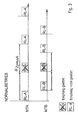
- Fig. 4a illustrated situation is that in Fig. 2b shown time pattern for three data telegrams in the variant 1, the last sent rest position data telegrams RL are illustrated as a basis for the following transmission scenarios.
- Fig. 4a and the following Fig. 4b - 4f t Skip marks the time in the sequence of data telegrams on which a respective probe touches the workpiece. At this time t Skip is changed from normal operation to trigger operation and the probe starts sending the sequence of data telegrams for trigger operation.
- Fig. 4a and the following Fig. 4b - 4f t Out denotes the time at which the receiving part ( Fig. 5 , ET) forwards the received status to the machine control (CNC).
- CNC machine control
- the approach presented here ensures that, on the one hand, the time difference between the times t Skip and t Out is as short as possible and, on the other hand, that this time difference is the same in all cases.
- the in Fig. 4b illustrated situation with which the in Fig. 2b shown time pattern for three data telegrams in the variant 1 are the last sent rest position data telegrams RL and the data telegrams DTA1, BTB1 disturbed.
- the switching point data telegrams DTA2, BTB2 are transmitted delayed and therefore correctly received by the receiving part ET.
- the signal output CA of the receiving part ET to the CNC control for the probe MTA is active after a delay time of 8 time grids connected.
- the signal output CB of the receiving part ET to the CNC control for the probe MTB is activated after a delay time of 8 time grids.
- the switching point of the probe MTA in the data telegram DTA1 collides with the rest position data telegram RL-B of the probe MTB. All subsequent data telegrams of the measuring probes MTA and MTB can be received correctly by the receiving part ET.
- the signal output CA of the receiving part ET to the CNC control for the probe MTA is activated after a delay time of 6 time frames after receiving / decoding the data telegram DTA2 of the first probe MTA active.
- the signal output CB of the receiving part ET to the CNC control for the probe MTB is switched to active after a delay time of 8 time frames after receiving / decoding the first data telegram DTB1 the second probe MTB.
- the switching point of the first probe MTA in the data telegram DTA1 collides with the rest position data telegram RL-B of the second probe MTB, as well as the data telegrams DTB1 and DTA2 of the first and second probes MTA, MTB.
- the second data telegram DTB2 of the second measuring probe MTB and the third data telegram DTA3 of the first measuring probe MTA can be received correctly by the receiving part ET.
- the signal output CA of the receiving part ET to the CNC control for the probe MTA is activated immediately after receiving / decoding the third data telegram DTA3 of the first probe MTA active.
- the signal output CB of the receiving part ET to the CNC control for the probe MTB is switched to active after a delay time of 4 time frames after receiving / decoding the second data telegram DTB2 the second probe MTB.
- Fig. 4e illustrated situation collide the two rest position data telegrams RL-A and RL-B of the first and second probe MTA, MTB, and the first data telegrams DTA1, DTB1 the first and second probes MTA, MTB.
- the second data telegrams DTA2, DTB2 of the first and second measuring probes MTA, MTB can be received correctly by the receiving part ET.
- the signal output CA of the receiving part ET to the CNC control for the probe MTA is activated after a delay time of 6 time frames after receiving / decoding the third data telegram DTA3 of the first probe MTA active.
- the signal output CB of the receiving part ET to the CNC control for the probe MTB is activated after a delay time of 4 time frames after receiving / decoding the second data telegram DTB2 the second probe MTB.
- the rest position data telegram RL-B and the first data telegram DTB1 of the first probe MTB collide with the rest position data telegram RL-A of the first probe MTA, and the second data telegrams DTA2, DTB2 of the first and second probes MTA, MTB.
- the first data telegram DTA1 of the first measuring probe MTA and the third data telegrams DTA3, DTB3 of the first and second measuring probes MTA, MTB can be received correctly by the receiving part ET.
- the signal output CA of the receiving part ET to the CNC control for the probe MTA is activated after a delay time of 8 time frames after receiving / decoding the first data telegram DTA1 the first probe MTA active.
- the signal output CB of the receiving part ET to the CNC control for the probe MTB is activated immediately after receiving / decoding the third data telegram DTB3 of the second probe MTB active.
- Fig. 5 are also specially adapted and suitable for transmitting measured signals obtained in measurements carried out together with at least one further measuring probe in a machining center.
- Each probe adapted to each be included in a spindle of the machining center.
- Each probe has a housing in which a support bearing is formed, which defines an X, Y bearing plane and a normal central axis Z of the probe.
- a Tastrich technique is centrally located to receive a stylus and a transmission member is slidably guided in the housing along the central axis Z in order to implement any deflections of the support body from its rest position into rectilinear movements.
- a sensor converts the movements of the transmission element into measurement signals which are processed in a probe-side signal conditioning unit SAE for transmission to a receiving part ET.
- the signal conditioning unit SAE is set up and programmed to transmit data telegrams via a common transmission channel assigned to all the receiving part ET for reception by the receiving part ET. In each case two or more data telegrams are transmitted by the signal conditioning unit SAE of the respective probe MTA, MTB ... MTm. become.
- Each of the data telegrams comprises a characteristic for the respective probe information, a characteristic of the particular probe identifier, and an ordinal number of the respective data telegram, with which the characteristic information for the respective probe is transmitted.
- the signal conditioning unit SAE of the respective probe ensures that a substantially constant cycle time elapses between the beginning of two data telegrams of a probe with the same ordinal number.
- the signal conditioning unit SAE of the respective probe also ensures that a substantially constant pause time elapses between successive data telegrams of a probe with a different ordinal number.
- the signal processing unit of the respective probe ensures that the pause time between the data telegrams for each of the respective probes depending on a number of communicating with the receiving part probe in the machining center, the cycle time of each of the probes between two of their data telegrams with the same atomic number and / or a transmission time for a single one of the data telegrams is different.
- Each of the measuring probes can be equipped with a switch in order to be able to switch the signal conditioning unit SAE of the respective measuring probe between the different sequences of the data telegrams.
- the receiving part ET signal with a corresponding assignment send out to program the signal conditioning unit SAE of each probe accordingly.
Landscapes
- Physics & Mathematics (AREA)
- General Physics & Mathematics (AREA)
- Engineering & Computer Science (AREA)
- Computer Networks & Wireless Communication (AREA)
- Arrangements For Transmission Of Measured Signals (AREA)
Applications Claiming Priority (1)
| Application Number | Priority Date | Filing Date | Title |
|---|---|---|---|
| DE102013008182.3A DE102013008182A1 (de) | 2013-05-13 | 2013-05-13 | Verfahren zur Übertragung von Messsignalen in einem Bearbeitungszentrum mit zwei oder mehr Spindeln; Messtaster und Empfänger für das Verfahren |
Publications (2)
| Publication Number | Publication Date |
|---|---|
| EP2803943A1 true EP2803943A1 (fr) | 2014-11-19 |
| EP2803943B1 EP2803943B1 (fr) | 2018-02-07 |
Family
ID=50774603
Family Applications (1)
| Application Number | Title | Priority Date | Filing Date |
|---|---|---|---|
| EP14001583.5A Active EP2803943B1 (fr) | 2013-05-13 | 2014-05-06 | Procédé de transmission de signaux de mesure dans un centre de traitement doté d'au moins deux broches; palpeur de mesure et récepteur pour le procédé |
Country Status (2)
| Country | Link |
|---|---|
| EP (1) | EP2803943B1 (fr) |
| DE (1) | DE102013008182A1 (fr) |
Cited By (1)
| Publication number | Priority date | Publication date | Assignee | Title |
|---|---|---|---|---|
| EP2885606B1 (fr) | 2013-07-10 | 2016-07-20 | M&H Inprocess Messtechnik GmbH | Dispositif de mesure destiné à une machine-outil |
Families Citing this family (2)
| Publication number | Priority date | Publication date | Assignee | Title |
|---|---|---|---|---|
| DE102019006466A1 (de) | 2019-09-11 | 2021-03-11 | Blum-Novotest Gmbh | Werkzeugschneiden-Verstellkopf, Verfahren zu dessen Betrieb und zur Korrektur des Werkzeugschneiden-Verschleißes |
| CN111336962B (zh) * | 2020-02-25 | 2021-11-12 | 深圳星友方科技有限公司 | 火花机在线测量工件的方法及系统 |
Citations (2)
| Publication number | Priority date | Publication date | Assignee | Title |
|---|---|---|---|---|
| US20050166413A1 (en) * | 2003-04-28 | 2005-08-04 | Crampton Stephen J. | CMM arm with exoskeleton |
| DE10262188B4 (de) | 2002-08-29 | 2010-05-12 | Blum-Novotest Gmbh | Multidirektionaler Messtaster |
-
2013
- 2013-05-13 DE DE102013008182.3A patent/DE102013008182A1/de not_active Withdrawn
-
2014
- 2014-05-06 EP EP14001583.5A patent/EP2803943B1/fr active Active
Patent Citations (2)
| Publication number | Priority date | Publication date | Assignee | Title |
|---|---|---|---|---|
| DE10262188B4 (de) | 2002-08-29 | 2010-05-12 | Blum-Novotest Gmbh | Multidirektionaler Messtaster |
| US20050166413A1 (en) * | 2003-04-28 | 2005-08-04 | Crampton Stephen J. | CMM arm with exoskeleton |
Cited By (1)
| Publication number | Priority date | Publication date | Assignee | Title |
|---|---|---|---|---|
| EP2885606B1 (fr) | 2013-07-10 | 2016-07-20 | M&H Inprocess Messtechnik GmbH | Dispositif de mesure destiné à une machine-outil |
Also Published As
| Publication number | Publication date |
|---|---|
| DE102013008182A1 (de) | 2014-11-13 |
| EP2803943B1 (fr) | 2018-02-07 |
Similar Documents
| Publication | Publication Date | Title |
|---|---|---|
| WO2005119173A1 (fr) | Dispositif et procede pour la mesure de coordonnees | |
| EP3014313B1 (fr) | Procédé de synchronisation d'une barrière lumineuse | |
| EP2803943B1 (fr) | Procédé de transmission de signaux de mesure dans un centre de traitement doté d'au moins deux broches; palpeur de mesure et récepteur pour le procédé | |
| DE102010037681B4 (de) | Lichtgitter und Verfahren zur Objektvermessung mit einem Lichtgitter | |
| EP3840916A1 (fr) | Contrôle d'outil dans une machine d'usinage de pièces ouvrées | |
| EP4018159B1 (fr) | Système de mesure | |
| EP2917796B1 (fr) | Dispositif pour améliorer les procédés de production | |
| EP3336628A1 (fr) | Procédé et dispositif mobile d'analyse de cycle de production d'une machine de production ainsi que programme informatique, ensemble d'analyse de cycle de production de la machine de production et valise | |
| WO2017045886A1 (fr) | Procédé d'affectation de dispositifs de contrôle de la pression des pneus en fonction de la position de roues d'un véhicule | |
| DE102012022116A1 (de) | Messvorrichtung für eine Werkzeugmaschine | |
| DE102015007522A1 (de) | Numerisches Steuersystem | |
| DE102014102837B3 (de) | Vorrichtung zur Werkzeugkontrolle | |
| DE202014100965U1 (de) | Vorrichtung zur Werkzeugkontrolle | |
| WO2008046640A1 (fr) | Système et procédé de commande d'un dispositif de déplacement | |
| EP2885606B1 (fr) | Dispositif de mesure destiné à une machine-outil | |
| WO2021032382A1 (fr) | Dispositif d'étalonnage de la vitesse d'un axe de déplacement d'une machine | |
| EP4018155A1 (fr) | Système de mesure | |
| DE102018006652A1 (de) | Verfahren zur Werkzeugkontrolle | |
| DE112014006728B4 (de) | Verfahren zum Steuern eines Sensorsystems | |
| DE10132554A1 (de) | Verfahren zum Betreiben eines Tastsystems sowie Tastsystem zur Ausführung des Verfahrens | |
| EP4018153A1 (fr) | Unité de mesure | |
| EP1445574B1 (fr) | Système palpeur avec un dispositif pour évaluer les signaux d'émission | |
| DE102013016309A1 (de) | Vorrichtung und Verfahren zur Gerätesteuerung in einer numerisch gesteuerten Werkstückbearbeitungsmaschine | |
| EP1445575B1 (fr) | Procédé et dispositif pour évaluer les signaux d'émission d'un système palpeur | |
| DE102021101756A1 (de) | Verfahren zur 3D-Erfassung eines Messobjektes |
Legal Events
| Date | Code | Title | Description |
|---|---|---|---|
| PUAI | Public reference made under article 153(3) epc to a published international application that has entered the european phase |
Free format text: ORIGINAL CODE: 0009012 |
|
| 17P | Request for examination filed |
Effective date: 20140506 |
|
| AK | Designated contracting states |
Kind code of ref document: A1 Designated state(s): AL AT BE BG CH CY CZ DE DK EE ES FI FR GB GR HR HU IE IS IT LI LT LU LV MC MK MT NL NO PL PT RO RS SE SI SK SM TR |
|
| AX | Request for extension of the european patent |
Extension state: BA ME |
|
| RIN1 | Information on inventor provided before grant (corrected) |
Inventor name: FRICK, THOMAS Inventor name: HAEFELE, STEFAN Inventor name: RITTLER, WOLFGANG |
|
| R17P | Request for examination filed (corrected) |
Effective date: 20150505 |
|
| RBV | Designated contracting states (corrected) |
Designated state(s): AL AT BE BG CH CY CZ DE DK EE ES FI FR GB GR HR HU IE IS IT LI LT LU LV MC MK MT NL NO PL PT RO RS SE SI SK SM TR |
|
| 17Q | First examination report despatched |
Effective date: 20150902 |
|
| STAA | Information on the status of an ep patent application or granted ep patent |
Free format text: STATUS: EXAMINATION IS IN PROGRESS |
|
| REG | Reference to a national code |
Ref country code: DE Ref legal event code: R079 Ref document number: 502014007185 Country of ref document: DE Free format text: PREVIOUS MAIN CLASS: G01B0021040000 Ipc: G01B0005012000 |
|
| RIC1 | Information provided on ipc code assigned before grant |
Ipc: G01B 21/04 20060101ALI20170705BHEP Ipc: H04L 12/54 20130101ALI20170705BHEP Ipc: G01B 5/012 20060101AFI20170705BHEP |
|
| GRAP | Despatch of communication of intention to grant a patent |
Free format text: ORIGINAL CODE: EPIDOSNIGR1 |
|
| STAA | Information on the status of an ep patent application or granted ep patent |
Free format text: STATUS: GRANT OF PATENT IS INTENDED |
|
| INTG | Intention to grant announced |
Effective date: 20170825 |
|
| GRAS | Grant fee paid |
Free format text: ORIGINAL CODE: EPIDOSNIGR3 |
|
| GRAA | (expected) grant |
Free format text: ORIGINAL CODE: 0009210 |
|
| STAA | Information on the status of an ep patent application or granted ep patent |
Free format text: STATUS: THE PATENT HAS BEEN GRANTED |
|
| AK | Designated contracting states |
Kind code of ref document: B1 Designated state(s): AL AT BE BG CH CY CZ DE DK EE ES FI FR GB GR HR HU IE IS IT LI LT LU LV MC MK MT NL NO PL PT RO RS SE SI SK SM TR |
|
| REG | Reference to a national code |
Ref country code: GB Ref legal event code: FG4D Free format text: NOT ENGLISH |
|
| REG | Reference to a national code |
Ref country code: AT Ref legal event code: REF Ref document number: 968973 Country of ref document: AT Kind code of ref document: T Effective date: 20180215 Ref country code: CH Ref legal event code: EP |
|
| REG | Reference to a national code |
Ref country code: IE Ref legal event code: FG4D Free format text: LANGUAGE OF EP DOCUMENT: GERMAN |
|
| REG | Reference to a national code |
Ref country code: DE Ref legal event code: R096 Ref document number: 502014007185 Country of ref document: DE |
|
| REG | Reference to a national code |
Ref country code: NL Ref legal event code: MP Effective date: 20180207 |
|
| PG25 | Lapsed in a contracting state [announced via postgrant information from national office to epo] |
Ref country code: CY Free format text: LAPSE BECAUSE OF FAILURE TO SUBMIT A TRANSLATION OF THE DESCRIPTION OR TO PAY THE FEE WITHIN THE PRESCRIBED TIME-LIMIT Effective date: 20180207 Ref country code: LT Free format text: LAPSE BECAUSE OF FAILURE TO SUBMIT A TRANSLATION OF THE DESCRIPTION OR TO PAY THE FEE WITHIN THE PRESCRIBED TIME-LIMIT Effective date: 20180207 Ref country code: HR Free format text: LAPSE BECAUSE OF FAILURE TO SUBMIT A TRANSLATION OF THE DESCRIPTION OR TO PAY THE FEE WITHIN THE PRESCRIBED TIME-LIMIT Effective date: 20180207 Ref country code: NO Free format text: LAPSE BECAUSE OF FAILURE TO SUBMIT A TRANSLATION OF THE DESCRIPTION OR TO PAY THE FEE WITHIN THE PRESCRIBED TIME-LIMIT Effective date: 20180507 Ref country code: NL Free format text: LAPSE BECAUSE OF FAILURE TO SUBMIT A TRANSLATION OF THE DESCRIPTION OR TO PAY THE FEE WITHIN THE PRESCRIBED TIME-LIMIT Effective date: 20180207 Ref country code: ES Free format text: LAPSE BECAUSE OF FAILURE TO SUBMIT A TRANSLATION OF THE DESCRIPTION OR TO PAY THE FEE WITHIN THE PRESCRIBED TIME-LIMIT Effective date: 20180207 Ref country code: FI Free format text: LAPSE BECAUSE OF FAILURE TO SUBMIT A TRANSLATION OF THE DESCRIPTION OR TO PAY THE FEE WITHIN THE PRESCRIBED TIME-LIMIT Effective date: 20180207 |
|
| PG25 | Lapsed in a contracting state [announced via postgrant information from national office to epo] |
Ref country code: PL Free format text: LAPSE BECAUSE OF FAILURE TO SUBMIT A TRANSLATION OF THE DESCRIPTION OR TO PAY THE FEE WITHIN THE PRESCRIBED TIME-LIMIT Effective date: 20180207 Ref country code: SE Free format text: LAPSE BECAUSE OF FAILURE TO SUBMIT A TRANSLATION OF THE DESCRIPTION OR TO PAY THE FEE WITHIN THE PRESCRIBED TIME-LIMIT Effective date: 20180207 Ref country code: LV Free format text: LAPSE BECAUSE OF FAILURE TO SUBMIT A TRANSLATION OF THE DESCRIPTION OR TO PAY THE FEE WITHIN THE PRESCRIBED TIME-LIMIT Effective date: 20180207 Ref country code: GR Free format text: LAPSE BECAUSE OF FAILURE TO SUBMIT A TRANSLATION OF THE DESCRIPTION OR TO PAY THE FEE WITHIN THE PRESCRIBED TIME-LIMIT Effective date: 20180508 Ref country code: IS Free format text: LAPSE BECAUSE OF FAILURE TO SUBMIT A TRANSLATION OF THE DESCRIPTION OR TO PAY THE FEE WITHIN THE PRESCRIBED TIME-LIMIT Effective date: 20180607 Ref country code: BG Free format text: LAPSE BECAUSE OF FAILURE TO SUBMIT A TRANSLATION OF THE DESCRIPTION OR TO PAY THE FEE WITHIN THE PRESCRIBED TIME-LIMIT Effective date: 20180507 Ref country code: RS Free format text: LAPSE BECAUSE OF FAILURE TO SUBMIT A TRANSLATION OF THE DESCRIPTION OR TO PAY THE FEE WITHIN THE PRESCRIBED TIME-LIMIT Effective date: 20180207 |
|
| PG25 | Lapsed in a contracting state [announced via postgrant information from national office to epo] |
Ref country code: MT Free format text: LAPSE BECAUSE OF FAILURE TO SUBMIT A TRANSLATION OF THE DESCRIPTION OR TO PAY THE FEE WITHIN THE PRESCRIBED TIME-LIMIT Effective date: 20180207 |
|
| PG25 | Lapsed in a contracting state [announced via postgrant information from national office to epo] |
Ref country code: AL Free format text: LAPSE BECAUSE OF FAILURE TO SUBMIT A TRANSLATION OF THE DESCRIPTION OR TO PAY THE FEE WITHIN THE PRESCRIBED TIME-LIMIT Effective date: 20180207 Ref country code: RO Free format text: LAPSE BECAUSE OF FAILURE TO SUBMIT A TRANSLATION OF THE DESCRIPTION OR TO PAY THE FEE WITHIN THE PRESCRIBED TIME-LIMIT Effective date: 20180207 Ref country code: EE Free format text: LAPSE BECAUSE OF FAILURE TO SUBMIT A TRANSLATION OF THE DESCRIPTION OR TO PAY THE FEE WITHIN THE PRESCRIBED TIME-LIMIT Effective date: 20180207 |
|
| REG | Reference to a national code |
Ref country code: DE Ref legal event code: R097 Ref document number: 502014007185 Country of ref document: DE |
|
| PG25 | Lapsed in a contracting state [announced via postgrant information from national office to epo] |
Ref country code: SK Free format text: LAPSE BECAUSE OF FAILURE TO SUBMIT A TRANSLATION OF THE DESCRIPTION OR TO PAY THE FEE WITHIN THE PRESCRIBED TIME-LIMIT Effective date: 20180207 Ref country code: SM Free format text: LAPSE BECAUSE OF FAILURE TO SUBMIT A TRANSLATION OF THE DESCRIPTION OR TO PAY THE FEE WITHIN THE PRESCRIBED TIME-LIMIT Effective date: 20180207 Ref country code: CZ Free format text: LAPSE BECAUSE OF FAILURE TO SUBMIT A TRANSLATION OF THE DESCRIPTION OR TO PAY THE FEE WITHIN THE PRESCRIBED TIME-LIMIT Effective date: 20180207 Ref country code: DK Free format text: LAPSE BECAUSE OF FAILURE TO SUBMIT A TRANSLATION OF THE DESCRIPTION OR TO PAY THE FEE WITHIN THE PRESCRIBED TIME-LIMIT Effective date: 20180207 |
|
| PLBE | No opposition filed within time limit |
Free format text: ORIGINAL CODE: 0009261 |
|
| REG | Reference to a national code |
Ref country code: CH Ref legal event code: PL |
|
| STAA | Information on the status of an ep patent application or granted ep patent |
Free format text: STATUS: NO OPPOSITION FILED WITHIN TIME LIMIT |
|
| 26N | No opposition filed |
Effective date: 20181108 |
|
| REG | Reference to a national code |
Ref country code: BE Ref legal event code: MM Effective date: 20180531 |
|
| PG25 | Lapsed in a contracting state [announced via postgrant information from national office to epo] |
Ref country code: MC Free format text: LAPSE BECAUSE OF FAILURE TO SUBMIT A TRANSLATION OF THE DESCRIPTION OR TO PAY THE FEE WITHIN THE PRESCRIBED TIME-LIMIT Effective date: 20180207 |
|
| REG | Reference to a national code |
Ref country code: IE Ref legal event code: MM4A |
|
| PG25 | Lapsed in a contracting state [announced via postgrant information from national office to epo] |
Ref country code: SI Free format text: LAPSE BECAUSE OF FAILURE TO SUBMIT A TRANSLATION OF THE DESCRIPTION OR TO PAY THE FEE WITHIN THE PRESCRIBED TIME-LIMIT Effective date: 20180207 Ref country code: CH Free format text: LAPSE BECAUSE OF NON-PAYMENT OF DUE FEES Effective date: 20180531 Ref country code: LI Free format text: LAPSE BECAUSE OF NON-PAYMENT OF DUE FEES Effective date: 20180531 |
|
| PG25 | Lapsed in a contracting state [announced via postgrant information from national office to epo] |
Ref country code: LU Free format text: LAPSE BECAUSE OF NON-PAYMENT OF DUE FEES Effective date: 20180506 |
|
| PG25 | Lapsed in a contracting state [announced via postgrant information from national office to epo] |
Ref country code: FR Free format text: LAPSE BECAUSE OF NON-PAYMENT OF DUE FEES Effective date: 20180531 Ref country code: IE Free format text: LAPSE BECAUSE OF NON-PAYMENT OF DUE FEES Effective date: 20180506 |
|
| PG25 | Lapsed in a contracting state [announced via postgrant information from national office to epo] |
Ref country code: BE Free format text: LAPSE BECAUSE OF NON-PAYMENT OF DUE FEES Effective date: 20180531 |
|
| PG25 | Lapsed in a contracting state [announced via postgrant information from national office to epo] |
Ref country code: TR Free format text: LAPSE BECAUSE OF FAILURE TO SUBMIT A TRANSLATION OF THE DESCRIPTION OR TO PAY THE FEE WITHIN THE PRESCRIBED TIME-LIMIT Effective date: 20180207 |
|
| PG25 | Lapsed in a contracting state [announced via postgrant information from national office to epo] |
Ref country code: HU Free format text: LAPSE BECAUSE OF FAILURE TO SUBMIT A TRANSLATION OF THE DESCRIPTION OR TO PAY THE FEE WITHIN THE PRESCRIBED TIME-LIMIT; INVALID AB INITIO Effective date: 20140506 Ref country code: PT Free format text: LAPSE BECAUSE OF FAILURE TO SUBMIT A TRANSLATION OF THE DESCRIPTION OR TO PAY THE FEE WITHIN THE PRESCRIBED TIME-LIMIT Effective date: 20180207 |
|
| PG25 | Lapsed in a contracting state [announced via postgrant information from national office to epo] |
Ref country code: MK Free format text: LAPSE BECAUSE OF NON-PAYMENT OF DUE FEES Effective date: 20180207 |
|
| REG | Reference to a national code |
Ref country code: AT Ref legal event code: MM01 Ref document number: 968973 Country of ref document: AT Kind code of ref document: T Effective date: 20190506 |
|
| PG25 | Lapsed in a contracting state [announced via postgrant information from national office to epo] |
Ref country code: AT Free format text: LAPSE BECAUSE OF NON-PAYMENT OF DUE FEES Effective date: 20190506 |
|
| PGFP | Annual fee paid to national office [announced via postgrant information from national office to epo] |
Ref country code: IT Payment date: 20230526 Year of fee payment: 10 |
|
| PGFP | Annual fee paid to national office [announced via postgrant information from national office to epo] |
Ref country code: GB Payment date: 20240521 Year of fee payment: 11 |
|
| PGFP | Annual fee paid to national office [announced via postgrant information from national office to epo] |
Ref country code: DE Payment date: 20240521 Year of fee payment: 11 |