EP2803939B1 - Supply module for supplying a weapons system and weapons system with supply module - Google Patents
Supply module for supplying a weapons system and weapons system with supply module Download PDFInfo
- Publication number
- EP2803939B1 EP2803939B1 EP14001619.7A EP14001619A EP2803939B1 EP 2803939 B1 EP2803939 B1 EP 2803939B1 EP 14001619 A EP14001619 A EP 14001619A EP 2803939 B1 EP2803939 B1 EP 2803939B1
- Authority
- EP
- European Patent Office
- Prior art keywords
- supply module
- weapons system
- electrical
- weapon system
- storage apparatus
- Prior art date
- Legal status (The legal status is an assumption and is not a legal conclusion. Google has not performed a legal analysis and makes no representation as to the accuracy of the status listed.)
- Active
Links
Images
Classifications
-
- H—ELECTRICITY
- H05—ELECTRIC TECHNIQUES NOT OTHERWISE PROVIDED FOR
- H05K—PRINTED CIRCUITS; CASINGS OR CONSTRUCTIONAL DETAILS OF ELECTRIC APPARATUS; MANUFACTURE OF ASSEMBLAGES OF ELECTRICAL COMPONENTS
- H05K7/00—Constructional details common to different types of electric apparatus
- H05K7/20—Modifications to facilitate cooling, ventilating, or heating
- H05K7/2089—Modifications to facilitate cooling, ventilating, or heating for power electronics, e.g. for inverters for controlling motor
-
- H—ELECTRICITY
- H01—ELECTRIC ELEMENTS
- H01M—PROCESSES OR MEANS, e.g. BATTERIES, FOR THE DIRECT CONVERSION OF CHEMICAL ENERGY INTO ELECTRICAL ENERGY
- H01M10/00—Secondary cells; Manufacture thereof
- H01M10/05—Accumulators with non-aqueous electrolyte
- H01M10/052—Li-accumulators
-
- F—MECHANICAL ENGINEERING; LIGHTING; HEATING; WEAPONS; BLASTING
- F28—HEAT EXCHANGE IN GENERAL
- F28D—HEAT-EXCHANGE APPARATUS, NOT PROVIDED FOR IN ANOTHER SUBCLASS, IN WHICH THE HEAT-EXCHANGE MEDIA DO NOT COME INTO DIRECT CONTACT
- F28D20/00—Heat storage plants or apparatus in general; Regenerative heat-exchange apparatus not covered by groups F28D17/00 or F28D19/00
- F28D20/0034—Heat storage plants or apparatus in general; Regenerative heat-exchange apparatus not covered by groups F28D17/00 or F28D19/00 using liquid heat storage material
-
- F—MECHANICAL ENGINEERING; LIGHTING; HEATING; WEAPONS; BLASTING
- F28—HEAT EXCHANGE IN GENERAL
- F28D—HEAT-EXCHANGE APPARATUS, NOT PROVIDED FOR IN ANOTHER SUBCLASS, IN WHICH THE HEAT-EXCHANGE MEDIA DO NOT COME INTO DIRECT CONTACT
- F28D20/00—Heat storage plants or apparatus in general; Regenerative heat-exchange apparatus not covered by groups F28D17/00 or F28D19/00
- F28D20/02—Heat storage plants or apparatus in general; Regenerative heat-exchange apparatus not covered by groups F28D17/00 or F28D19/00 using latent heat
-
- F—MECHANICAL ENGINEERING; LIGHTING; HEATING; WEAPONS; BLASTING
- F41—WEAPONS
- F41H—ARMOUR; ARMOURED TURRETS; ARMOURED OR ARMED VEHICLES; MEANS OF ATTACK OR DEFENCE, e.g. CAMOUFLAGE, IN GENERAL
- F41H13/00—Means of attack or defence not otherwise provided for
- F41H13/0043—Directed energy weapons, i.e. devices that direct a beam of high energy content toward a target for incapacitating or destroying the target
-
- H—ELECTRICITY
- H01—ELECTRIC ELEMENTS
- H01M—PROCESSES OR MEANS, e.g. BATTERIES, FOR THE DIRECT CONVERSION OF CHEMICAL ENERGY INTO ELECTRICAL ENERGY
- H01M10/00—Secondary cells; Manufacture thereof
- H01M10/05—Accumulators with non-aqueous electrolyte
- H01M10/052—Li-accumulators
- H01M10/0525—Rocking-chair batteries, i.e. batteries with lithium insertion or intercalation in both electrodes; Lithium-ion batteries
-
- H—ELECTRICITY
- H01—ELECTRIC ELEMENTS
- H01M—PROCESSES OR MEANS, e.g. BATTERIES, FOR THE DIRECT CONVERSION OF CHEMICAL ENERGY INTO ELECTRICAL ENERGY
- H01M10/00—Secondary cells; Manufacture thereof
- H01M10/60—Heating or cooling; Temperature control
- H01M10/61—Types of temperature control
- H01M10/613—Cooling or keeping cold
-
- H—ELECTRICITY
- H01—ELECTRIC ELEMENTS
- H01M—PROCESSES OR MEANS, e.g. BATTERIES, FOR THE DIRECT CONVERSION OF CHEMICAL ENERGY INTO ELECTRICAL ENERGY
- H01M10/00—Secondary cells; Manufacture thereof
- H01M10/60—Heating or cooling; Temperature control
- H01M10/62—Heating or cooling; Temperature control specially adapted for specific applications
- H01M10/625—Vehicles
-
- F—MECHANICAL ENGINEERING; LIGHTING; HEATING; WEAPONS; BLASTING
- F28—HEAT EXCHANGE IN GENERAL
- F28D—HEAT-EXCHANGE APPARATUS, NOT PROVIDED FOR IN ANOTHER SUBCLASS, IN WHICH THE HEAT-EXCHANGE MEDIA DO NOT COME INTO DIRECT CONTACT
- F28D15/00—Heat-exchange apparatus with the intermediate heat-transfer medium in closed tubes passing into or through the conduit walls ; Heat-exchange apparatus employing intermediate heat-transfer medium or bodies
-
- F—MECHANICAL ENGINEERING; LIGHTING; HEATING; WEAPONS; BLASTING
- F28—HEAT EXCHANGE IN GENERAL
- F28D—HEAT-EXCHANGE APPARATUS, NOT PROVIDED FOR IN ANOTHER SUBCLASS, IN WHICH THE HEAT-EXCHANGE MEDIA DO NOT COME INTO DIRECT CONTACT
- F28D20/00—Heat storage plants or apparatus in general; Regenerative heat-exchange apparatus not covered by groups F28D17/00 or F28D19/00
- F28D2020/0004—Particular heat storage apparatus
- F28D2020/0026—Particular heat storage apparatus the heat storage material being enclosed in mobile containers for transporting thermal energy
-
- F—MECHANICAL ENGINEERING; LIGHTING; HEATING; WEAPONS; BLASTING
- F28—HEAT EXCHANGE IN GENERAL
- F28D—HEAT-EXCHANGE APPARATUS, NOT PROVIDED FOR IN ANOTHER SUBCLASS, IN WHICH THE HEAT-EXCHANGE MEDIA DO NOT COME INTO DIRECT CONTACT
- F28D21/00—Heat-exchange apparatus not covered by any of the groups F28D1/00 - F28D20/00
- F28D2021/0019—Other heat exchangers for particular applications; Heat exchange systems not otherwise provided for
- F28D2021/0028—Other heat exchangers for particular applications; Heat exchange systems not otherwise provided for for cooling heat generating elements, e.g. for cooling electronic components or electric devices
-
- F—MECHANICAL ENGINEERING; LIGHTING; HEATING; WEAPONS; BLASTING
- F28—HEAT EXCHANGE IN GENERAL
- F28F—DETAILS OF HEAT-EXCHANGE AND HEAT-TRANSFER APPARATUS, OF GENERAL APPLICATION
- F28F2280/00—Mounting arrangements; Arrangements for facilitating assembling or disassembling of heat exchanger parts
- F28F2280/02—Removable elements
-
- H—ELECTRICITY
- H01—ELECTRIC ELEMENTS
- H01M—PROCESSES OR MEANS, e.g. BATTERIES, FOR THE DIRECT CONVERSION OF CHEMICAL ENERGY INTO ELECTRICAL ENERGY
- H01M2220/00—Batteries for particular applications
- H01M2220/20—Batteries in motive systems, e.g. vehicle, ship, plane
-
- H—ELECTRICITY
- H01—ELECTRIC ELEMENTS
- H01S—DEVICES USING THE PROCESS OF LIGHT AMPLIFICATION BY STIMULATED EMISSION OF RADIATION [LASER] TO AMPLIFY OR GENERATE LIGHT; DEVICES USING STIMULATED EMISSION OF ELECTROMAGNETIC RADIATION IN WAVE RANGES OTHER THAN OPTICAL
- H01S3/00—Lasers, i.e. devices using stimulated emission of electromagnetic radiation in the infrared, visible or ultraviolet wave range
- H01S3/02—Constructional details
- H01S3/04—Arrangements for thermal management
- H01S3/0407—Liquid cooling, e.g. by water
-
- H—ELECTRICITY
- H01—ELECTRIC ELEMENTS
- H01S—DEVICES USING THE PROCESS OF LIGHT AMPLIFICATION BY STIMULATED EMISSION OF RADIATION [LASER] TO AMPLIFY OR GENERATE LIGHT; DEVICES USING STIMULATED EMISSION OF ELECTROMAGNETIC RADIATION IN WAVE RANGES OTHER THAN OPTICAL
- H01S3/00—Lasers, i.e. devices using stimulated emission of electromagnetic radiation in the infrared, visible or ultraviolet wave range
- H01S3/09—Processes or apparatus for excitation, e.g. pumping
- H01S3/091—Processes or apparatus for excitation, e.g. pumping using optical pumping
- H01S3/094—Processes or apparatus for excitation, e.g. pumping using optical pumping by coherent light
- H01S3/0941—Processes or apparatus for excitation, e.g. pumping using optical pumping by coherent light of a laser diode
-
- H—ELECTRICITY
- H01—ELECTRIC ELEMENTS
- H01S—DEVICES USING THE PROCESS OF LIGHT AMPLIFICATION BY STIMULATED EMISSION OF RADIATION [LASER] TO AMPLIFY OR GENERATE LIGHT; DEVICES USING STIMULATED EMISSION OF ELECTROMAGNETIC RADIATION IN WAVE RANGES OTHER THAN OPTICAL
- H01S5/00—Semiconductor lasers
- H01S5/04—Processes or apparatus for excitation, e.g. pumping, e.g. by electron beams
- H01S5/042—Electrical excitation ; Circuits therefor
-
- Y—GENERAL TAGGING OF NEW TECHNOLOGICAL DEVELOPMENTS; GENERAL TAGGING OF CROSS-SECTIONAL TECHNOLOGIES SPANNING OVER SEVERAL SECTIONS OF THE IPC; TECHNICAL SUBJECTS COVERED BY FORMER USPC CROSS-REFERENCE ART COLLECTIONS [XRACs] AND DIGESTS
- Y02—TECHNOLOGIES OR APPLICATIONS FOR MITIGATION OR ADAPTATION AGAINST CLIMATE CHANGE
- Y02E—REDUCTION OF GREENHOUSE GAS [GHG] EMISSIONS, RELATED TO ENERGY GENERATION, TRANSMISSION OR DISTRIBUTION
- Y02E60/00—Enabling technologies; Technologies with a potential or indirect contribution to GHG emissions mitigation
- Y02E60/10—Energy storage using batteries
-
- Y—GENERAL TAGGING OF NEW TECHNOLOGICAL DEVELOPMENTS; GENERAL TAGGING OF CROSS-SECTIONAL TECHNOLOGIES SPANNING OVER SEVERAL SECTIONS OF THE IPC; TECHNICAL SUBJECTS COVERED BY FORMER USPC CROSS-REFERENCE ART COLLECTIONS [XRACs] AND DIGESTS
- Y02—TECHNOLOGIES OR APPLICATIONS FOR MITIGATION OR ADAPTATION AGAINST CLIMATE CHANGE
- Y02E—REDUCTION OF GREENHOUSE GAS [GHG] EMISSIONS, RELATED TO ENERGY GENERATION, TRANSMISSION OR DISTRIBUTION
- Y02E60/00—Enabling technologies; Technologies with a potential or indirect contribution to GHG emissions mitigation
- Y02E60/14—Thermal energy storage
Definitions
- the present invention relates to a storage module for supplying a weapon system. Furthermore, the present invention comprises an active system, comprising a weapon system to be supplied and the storage module. Particularly preferably, the weapon system to be supplied is a laser weapon system.
- the weapon system to be supplied is a laser weapon system.
- diode-pumped solid-state lasers in the power class of about 100 kW are often proposed for generating the laser radiation.
- the proposed high energy laser weapons systems have laser devices that typically have an efficiency of about 20%. Therefore, a very high cooling capacity of 80% of the applied electrical power is necessary in operation, with a stabilization of the coolant temperature to a few degrees Celsius is needed exactly.
- the cooling of the laser devices represents a very great challenge. From the prior art it is known that the electrical supply and cooling of laser devices can be done with a suitably sized electrical generator and a sufficiently large cooling unit. But such supply devices have a very large mass and a very large volume in the required services. In particular, a realization of a laser weapon on a mobile carrier vehicle is impossible.
- the US2011 / 113949A1 forms a starting point for claim 1 and discloses an electric and a thermal storage module for supplying a weapon system.
- an underwater vehicle that comprises a laser active system. Since underwater vehicles usually already have power generation and cooling systems, the laser weapon system relies on said systems of the underwater vehicle.
- an electro-hydraulic unit is known.
- an electric motor drives a pump, by means of which a fluid pressure is built up in the hydraulic system.
- a fluid pressure is built up in the hydraulic system.
- an accumulator the hydraulic pressure is finally stored, thus providing a hydraulic power reserve available.
- Last is from the DE 10 2008 054 264 B4 a multi-functional service and testing facility for unmanned aerial vehicles known.
- the service and test device also includes the possibility of supplying the missile with externally supplied electrical energy from the power network of the service device.
- the object is achieved by a storage module that can be used to supply a weapon system.
- the storage module according to the invention comprises an electrical storage device and a thermal storage device.
- the electrical storage device is designed to store electrical energy over a long period of time.
- the thermal storage device is configured to store a coolant.
- at least one electrical connection is present, via which electrical energy can be transmitted from the electrical storage device to the active system.
- a thermal connection allows the transfer of the coolant from the thermal storage device to the active system.
- the invention provides that the supply module for supplying the weapon system is interchangeable.
- the invention furthermore relates to an active system which comprises at least one weapon system to be supplied and at least one supply module, as described above or according to one of the refinements explained below.
- the weapon system to be supplied is in particular a laser weapon.
- the active system comprises at least one receiving device, which is firmly connected to the weapon system.
- the storage module can be introduced into the receiving device, so that the weapon system is supplied with electrical energy and with the coolant from the storage module. Therefore, it is preferably provided that the receiving device via a fluid line and via an electrical line with connected to the weapon system.
- this connection can be made solid, since the supply module can preferably be connected to the receiving device via the electrical connection and the thermal connection, so that electrical energy and coolant can be removed from the supply module.
- the supply module for supplying the weapon system is interchangeable, so that the weapon system is not ready for use after an operating time that consumes the supplies of the storage module, only for the time of changing the storage module.
- the supply module can be reused in particular by replenishing its supplies.
- the electrical connection and / or the thermal connection of the storage module comprises a quick release coupling. Therefore, the storage module can be quickly, easily and reliably connected to the weapon system to provide the weapon system with coolant and electrical energy.
- the rapidly releasable couplings of the electrical connection or of the thermal connection can be contacted with the weapon system either together or independently of one another.
- the electrical storage device is designed such that it has a power density of at least 1000 watts per kilogram (W / kg). In particular, the electrical storage device has a power density of at least 3000 W / kg. Alternatively or additionally, it is provided that the energy density of the electrical storage device amounts to at least 100 watt-hours per kilogram (Wh / kg). In particular, the energy density is at least 120 Wh / kg. With such a power supply, it is possible, in particular, to realize a maximum operating time of the weapon system with minimal weight and minimum volume of the electrical storage device.
- the electrical storage device may provide power to the weapon system for an operating time of at least 100 seconds maintained. More preferably, the electrical storage device can maintain the operating time for at least 150 seconds.
- the weapon system is sufficiently long available to ward off threats.
- the electrical storage device preferably comprises lithium iron phosphate accumulators.
- Such accumulators have a long life, a low self-discharge and can often be recharged. Therefore, such accumulators are very well suited for use in weapons systems.
- the lithium iron phosphate accumulators are rechargeable at least 1000 times.
- the thermal storage device comprises a latent heat storage.
- the cooling fluid contains a material which changes its phase when heat is absorbed without changing its temperature.
- such a material may include paraffin, such that cooling of the weapon system is accomplished by converting the paraffin from a solid state to a liquid state.
- the coolant may comprise an aqueous emulsion in which paraffin-filled plastic capsules are present. The diameters of the plastic capsules are in particular 5 microns.
- Such a cooling fluid is very advantageous for the cooling of laser systems, since this always maintains its temperature, while the cooling is realized by the phase transformation of the paraffin.
- the coolant has a latent heat capacity of at least 20 kilojoules per kilogram (kJ / kg).
- the coolant has a latent heat capacity of at least 40 kJ / kg.
- a phase transition temperature is defined in particular at 20 ° C.
- the active system according to the invention is preferably designed such that a loading device is present.
- the loading device may preferably be Be a crane.
- the storage module can be introduced into the receiving device and / or be brought out of the receiving device. Due to the advantageous loading device, therefore, the storage module is quickly and easily replaceable, so that only a short service life is necessary during which the weapon system to be supplied is not ready for use.
- At least two receiving devices are present, wherein a supply of the weapon system between the receiving devices is switchable.
- the weapon system is continuously operable, since it can be switched from a first supply module to a second supply module when the first supply module is consumed.
- the first storage module can be removed from the receiving device, since the supply of the weapon system is ensured by the second storage module.
- a third supply module can be introduced into the receiving device of the first supply module, so that can be switched to the third supply module after the consumption of the second supply module. It is obvious that in this way a continuous operation of the weapon system is possible.
- the active system comprises a platform.
- the weapon system and the at least one receiving device are preferably mounted on the platform.
- the platform is designed as a mobile platform, in particular as a land vehicle or as a watercraft. This has the advantage that the weapon system can always be brought to a location where it is needed.
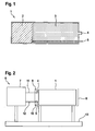
- FIG. 1 shows a storage module 1 according to an embodiment of the invention.
- the storage module 1 comprises an electrical storage device 2 and a thermal storage device 3.
- the electrical storage device 2 is connected to an electrical connection 5, which is designed in particular as a quick-release coupling. Via the electrical connection 5, the energy of the electrical storage device can be discharged.
- a thermal connection 4 is provided, which is also designed as a quick release coupling. Via the thermal connection 4, a coolant stored within the thermal storage device 3 can be discharged.
- the module consists of a cylindrical container made of steel or aluminum with a diameter of 0.5 m and a length of 1.5 m.
- the electric storage device 2 is attached in the form of electric storage batteries, while the thermal storage device 3 comprises a cooling liquid comprising a latent heat storage material.
- the electrical energy is preferably stored by means of lithium iron phosphate batteries having a power density of 3000 W / kg and an energy density of 120 Wh / kg.
- a power of 50 kW can be outputted for 140 seconds, the electric storage device having a mass of only 16.7 kg and a volume of 50 l.
- the thermal storage device 3 comprises a coolant comprising an aqueous emulsion of paraffin-filled plastic capsules.
- the plastic capsules preferably have a dimension of about 5 microns.
- This emulsion has a latent heat capacity of 40 kJ / kg at a predefined phase transition temperature.
- This phase transition temperature is in particular 20 ° C.
- the thermal storage device has a mass of 100 kg at a volume of 100 l. Thus, it is possible to provide 4 MJ of cooling energy.
- the total mass of the supply module is about 170 kg. Therefore, the storage module 1 can be handled very easily.
- the storage module can be introduced into a receiving device 8, what in FIG. 2 is shown.
- FIG. 2 shows an active system 6, which includes a weapon system 7 to be supplied.
- the weapon system 7 is in particular a high-energy laser weapon system.
- the weapon system 7 is connected by means of a fluid line 11 and by means of an electrical line 12 to the receiving device 8.
- the receiving device 8 the storage module 1 described above can be introduced.
- the receiving device 8 makes it possible to connect the electrical connection 5 via an electrical coupling element 10 to the electrical line 12, in order thus to supply the weapon system 7 with electrical energy.
- the receiving device 8 by a thermal coupling element 9 allows the thermal connection 4 of the storage module 1 to connect to the thermal line 11 so as to supply the weapon system 7 with the coolant.
- an electrical control unit to be present within the weapon system 7, which regulates a power supply of the weapon system 7 from the electrical storage device 2. Also, there is provided a cooling pump that removes the coolant from the thermal storage device 3 and supplies the coolant to the thermal storage device 3 again. Between removal and supply of the coolant, the coolant is used to absorb waste heat of the weapon system 7 and dissipate.
- the weapon system 7 has in particular a power of 50 kW, wherein an optical beam power of 10 kW can be generated. Thus, the weapon system has an efficiency of 20%.
- the storage module 1 according to said Embodiment therefore allows the supply of the weapon system 7 for an operating time of at least 100 seconds.
- the weapon system 7 is ready for use within a very short period of time, so that the active system 6 is characterized in a high availability rate.
- the spent stock module 1 can then be prepared by a reuse device for reuse by charging the electrical storage device and re-cooling the coolant of the thermal storage device to a cool ready state by re-phase conversion.
- the active system 6 has at least two receiving devices 8. This makes it possible for a supply module 1 to be removed from one of the receiving devices 8, while another supply module 1 in the other receiving device 8 supplies the weapon system 7. This means that an exchange of the storage modules 1 during the operation of the weapon system 7 is possible. Thus, the weapon system 7 can also be operated in a steady state, which is not possible or only with great effort in known systems.
- the active system 6 is finally mounted on a platform 13. This means that both the weapon system 7 and the receiving device 8 are mounted on the platform 13.
- the platform 13 is preferably designed as a mobile platform, in particular as a land vehicle or as a watercraft. Therefore, the platform 13 allows a very variable and versatile use of the weapon system 7, since the active unit 6 can be quickly and easily relocated to a location where it is needed.
Landscapes
- Engineering & Computer Science (AREA)
- Chemical & Material Sciences (AREA)
- General Chemical & Material Sciences (AREA)
- Electrochemistry (AREA)
- Chemical Kinetics & Catalysis (AREA)
- Manufacturing & Machinery (AREA)
- General Engineering & Computer Science (AREA)
- Physics & Mathematics (AREA)
- Thermal Sciences (AREA)
- Mechanical Engineering (AREA)
- Microelectronics & Electronic Packaging (AREA)
- Remote Sensing (AREA)
- Radar, Positioning & Navigation (AREA)
- Materials Engineering (AREA)
- Secondary Cells (AREA)
- Battery Mounting, Suspending (AREA)
- Manipulator (AREA)
- Charge And Discharge Circuits For Batteries Or The Like (AREA)
- Cooling Or The Like Of Electrical Apparatus (AREA)
Description
Die vorliegende Erfindung betrifft ein Vorratsmodul zum Versorgen eines Waffensystems. Weiterhin umfasst die vorliegende Erfindung ein Wirksystem, umfassend ein zu versorgendes Waffensystem und das Vorratsmodul. Besonders bevorzugt ist das zu versorgende Waffensystem ein Laserwaffensystem.
Bei Konzepten für Hochenergielaser-Waffensysteme werden für die Erzeugung der Laserstrahlung oftmals diodengepumpte Festkörperlaser in der Leistungsklasse von etwa 100 kW vorgeschlagen. Die vorgeschlagenen Hochenergielaser-Waffensysteme besitzen Lasergeräte, die üblicherweise einen Wirkungsgrad von etwa 20% aufweisen. Daher ist im Betrieb eine sehr hohe Kühlleistung von 80% der aufgewandten elektrischen Leistung nötig, wobei eine Stabilisierung der Kühlmitteltemperatur auf wenige Grad Celsius genau vonnöten ist. Betrachtet man die zuvor genannte Größenordnung der diodengepumpten Festkörperlaser von einigen hundert Kilowatt, so stellt die Kühlung der Lasergeräte eine sehr große Herausforderung dar.
Aus dem Stand der Technik ist bekannt, dass die elektrische Versorgung und Kühlung von Lasergeräten mit einem entsprechend dimensionierten elektrischen Generator und einem hinreichend großen Kühlaggregat erfolgen kann. Solche Versorgungsgeräte besitzen aber bei den erforderlichen Leistungen eine sehr große Masse und ein sehr großes Volumen. Insbesondere eine Realisierung einer Laserwaffe auf einem mobilen Trägerfahrzeug wird dadurch unmöglich.The present invention relates to a storage module for supplying a weapon system. Furthermore, the present invention comprises an active system, comprising a weapon system to be supplied and the storage module. Particularly preferably, the weapon system to be supplied is a laser weapon system.
In concepts for high-energy laser weapon systems, diode-pumped solid-state lasers in the power class of about 100 kW are often proposed for generating the laser radiation. The proposed high energy laser weapons systems have laser devices that typically have an efficiency of about 20%. Therefore, a very high cooling capacity of 80% of the applied electrical power is necessary in operation, with a stabilization of the coolant temperature to a few degrees Celsius is needed exactly. Considering the aforementioned order of magnitude of the diode-pumped solid-state lasers of a few hundred kilowatts, the cooling of the laser devices represents a very great challenge.
From the prior art it is known that the electrical supply and cooling of laser devices can be done with a suitably sized electrical generator and a sufficiently large cooling unit. But such supply devices have a very large mass and a very large volume in the required services. In particular, a realization of a laser weapon on a mobile carrier vehicle is impossible.
Die
Weiterhin ist aus dem Stand der Technik bekannt, dass zur Versorgung der Hochenergielaser-Waffensysteme elektrische Akkumulatoren verwendet werden, die elektrische Energie zum Betreiben des Waffensystems zwischenspeichern. Eine Kühlung kann beispielsweise durch eine hohe Menge an Kühlflüssigkeit erfolgen, wobei sich die Kühlflüssigkeit während des Betriebs des Waffensystems sehr stark erwärmt. Diese Konzepte haben jedoch den großen Nachteil, dass nach einer gewissen Betriebszeit des Waffensystems (typische Dauer etwa eine Minute) ein längerer Zeitraum (typischerweise etwa 15 Minuten) benötigt wird, um die Akkumulatoren erneut aufzuladen und die Kühlflüssigkeit wieder zu entwärmen. Somit ist die Einsatzzeit des Waffensystems sehr stark eingeschränkt.Furthermore, it is known from the prior art that electric batteries are used to supply the high-energy laser weapon systems, which store electrical energy for operating the weapon system. Cooling can be done for example by a high amount of cooling liquid, wherein the cooling liquid heats up very strongly during operation of the weapon system. However, these concepts have the great disadvantage that after a certain operating time of the weapon system (typical duration about one minute) a longer period of time (typically about 15 minutes) is needed to recharge the batteries and to reheat the cooling liquid. Thus, the deployment time of the weapon system is very limited.
Aus der
Aus der
Aus der
Zuletzt ist aus der
Es ist daher Aufgabe der Erfindung, ein Versorgungsmodul für ein Waffensystem, insbesondere für ein Hochenergielaser-Waffensystem, bereitzustellen, das bei einfacher und kostengünstiger Herstellung und Montage ein geringes Gewicht und ein geringes Volumen aufweist, dabei aber einen langen Einsatzzeitraum des Waffensystems ermöglicht. Es ist weiter Aufgabe der Erfindung, ein Wirksystem bereitzustellen, das ebenfalls die zuvor genannten Eigenschaften erfüllt.It is therefore an object of the invention to provide a supply module for a weapon system, in particular for a high-energy laser weapon system, which has a low weight and a low volume with simple and cost-effective production and assembly, but allows a long deployment period of the weapon system. It is a further object of the invention to provide an active system which also fulfills the aforementioned properties.
Die Aufgabe wird gelöst durch die Merkmale der unabhängigen Ansprüche.The object is solved by the features of the independent claims.
Somit wird die Aufgabe gelöst durch ein Vorratsmodul, das zur Versorgung eines Waffensystems verwendbar ist. Das erfindungsgemäße Vorratsmodul umfasst eine elektrische Speichervorrichtung sowie eine thermische Speichervorrichtung. Die elektrische Speichervorrichtung ist insbesondere derart ausgelegt, dass diese elektrische Energie über einen langen Zeitraum speichert. Die thermische Speichervorrichtung ist ausgebildet, ein Kühlmittel zu speichern. Erfindungsgemäß ist weiterhin vorgesehen, dass zumindest ein elektrischer Anschluss vorhanden ist, über den elektrische Energie aus der elektrischen Speichervorrichtung an das Wirksystem übertragbar ist. Ein thermischer Anschluss erlaubt hingegen das Übertragen des Kühlmittels aus der thermischen Speichervorrichtung an das Wirksystem. Eine derartige Anordnung ist insbesondere dann vorteilhaft, wenn das Waffensystem mobil versorgt werden soll. Hier werden dann keine leistungsstarken Geräte zur Versorgung benötigt. Vielmehr ist erfindungsgemäß vorgesehen, dass das Vorratsmodul zum Versorgen des Waffensystems austauschbar ist.Thus, the object is achieved by a storage module that can be used to supply a weapon system. The storage module according to the invention comprises an electrical storage device and a thermal storage device. In particular, the electrical storage device is designed to store electrical energy over a long period of time. The thermal storage device is configured to store a coolant. According to the invention, it is further provided that at least one electrical connection is present, via which electrical energy can be transmitted from the electrical storage device to the active system. On the other hand, a thermal connection allows the transfer of the coolant from the thermal storage device to the active system. Such an arrangement is particularly advantageous when the weapon system is to be supplied mobile. Here then no powerful devices are needed for the supply. Rather, the invention provides that the supply module for supplying the weapon system is interchangeable.
Die Erfindung betrifft weiterhin ein Wirksystem, das zumindest ein zu versorgendes Waffensystem und zumindest ein Vorratsmodul, wie zuvor beschrieben oder gemäß einer der nachfolgend ausgeführten Weiterbildungen umfasst. Das zu versorgende Waffensystem ist insbesondere eine Laserwaffe. Weiterhin umfasst das Wirksystem zumindest eine Aufnahmevorrichtung, die fest mit dem Waffensystem verbunden ist. Dabei ist das Vorratsmodul in die Aufnahmevorrichtung einbringbar, so dass eine Versorgung des Waffensystems mit elektrischer Energie und mit dem Kühlmittel aus dem Vorratsmodul erfolgt. Daher ist bevorzugt vorgesehen, dass die Aufnahmevorrichtung über eine Fluidleitung und über eine elektrische Leitung mit dem Waffensystem verbunden ist. Diese Verbindung kann insbesondere fest ausgebildet sein, da das Vorratsmodul bevorzugt über den elektrischen Anschluss und den thermischen Anschluss mit der Aufnahmevorrichtung verbunden werden kann, so dass elektrische Energie und Kühlmittel aus dem Vorratsmodul entnommen werden kann. Somit ist vorteilhafterweise das Vorratsmodul zum Versorgen des Waffensystems austauschbar, so dass das Waffensystem nach einer Betriebszeit, die die Vorräte des Vorratsmoduls aufbraucht, nur für die Zeit des Wechselns des Vorratsmoduls nicht einsatzbereit ist. Das Vorratsmodul wiederum kann insbesondere wiederverwendet werden, indem dessen Vorräte wieder aufgefüllt werden.The invention furthermore relates to an active system which comprises at least one weapon system to be supplied and at least one supply module, as described above or according to one of the refinements explained below. The weapon system to be supplied is in particular a laser weapon. Furthermore, the active system comprises at least one receiving device, which is firmly connected to the weapon system. In this case, the storage module can be introduced into the receiving device, so that the weapon system is supplied with electrical energy and with the coolant from the storage module. Therefore, it is preferably provided that the receiving device via a fluid line and via an electrical line with connected to the weapon system. In particular, this connection can be made solid, since the supply module can preferably be connected to the receiving device via the electrical connection and the thermal connection, so that electrical energy and coolant can be removed from the supply module. Thus, advantageously, the supply module for supplying the weapon system is interchangeable, so that the weapon system is not ready for use after an operating time that consumes the supplies of the storage module, only for the time of changing the storage module. In turn, the supply module can be reused in particular by replenishing its supplies.
Die Unteransprüche haben bevorzugte Weiterbildungen der Erfindung zum Inhalt.The dependent claims have preferred developments of the invention to the content.
Bevorzugt wird vorgesehen, dass der elektrische Anschluss und/oder der thermische Anschluss des Vorratsmoduls eine schnell lösbare Kupplung umfasst. Daher kann das Vorratsmodul schnell, einfach und zuverlässig mit dem Waffensystem verbunden werden, um das Waffensystem mit Kühlmittel und elektrischer Energie zu versorgen. Dabei können die schnell lösbaren Kupplungen des elektrischen Anschlusses oder des thermischen Anschlusses entweder gemeinsam oder unabhängig voneinander mit dem Waffensystem kontaktiert werden.It is preferably provided that the electrical connection and / or the thermal connection of the storage module comprises a quick release coupling. Therefore, the storage module can be quickly, easily and reliably connected to the weapon system to provide the weapon system with coolant and electrical energy. The rapidly releasable couplings of the electrical connection or of the thermal connection can be contacted with the weapon system either together or independently of one another.
Vorteilhafterweise ist die elektrische Speichervorrichtung derart ausgebildet, dass diese eine Leistungsdichte von zumindest 1000 Watt pro Kilogramm (W/kg) aufweist. Insbesondere weist die elektrische Speichervorrichtung eine Leistungsdichte von zumindest 3000 W/kg auf. Alternativ oder zusätzlich ist vorgesehen, dass die Energiedichte der elektrischen Speichervorrichtung zumindest 100 Wattstunden pro Kilogramm (Wh/kg) beträgt. Insbesondere beträgt die Energiedichte zumindest 120 Wh/kg. Mit einer derartigen Energieversorgung ist es insbesondere möglich, bei minimalem Gewicht und minimalem Volumen der elektrischen Speichervorrichtung eine maximale Betriebszeit des Waffensystems zu realisieren.Advantageously, the electrical storage device is designed such that it has a power density of at least 1000 watts per kilogram (W / kg). In particular, the electrical storage device has a power density of at least 3000 W / kg. Alternatively or additionally, it is provided that the energy density of the electrical storage device amounts to at least 100 watt-hours per kilogram (Wh / kg). In particular, the energy density is at least 120 Wh / kg. With such a power supply, it is possible, in particular, to realize a maximum operating time of the weapon system with minimal weight and minimum volume of the electrical storage device.
Vorteilhafterweise kann die elektrische Speichervorrichtung eine Energieversorgung des Waffensystems für eine Betriebszeit von zumindest 100 Sekunden aufrechterhalten. Besonders bevorzugt kann die elektrische Speichervorrichtung die Betriebszeit zumindest 150 Sekunden aufrechterhalten. Somit ist das Waffensystem ausreichend lange verfügbar, um Bedrohungen abzuwehren.Advantageously, the electrical storage device may provide power to the weapon system for an operating time of at least 100 seconds maintained. More preferably, the electrical storage device can maintain the operating time for at least 150 seconds. Thus, the weapon system is sufficiently long available to ward off threats.
Bevorzugt umfasst die elektrische Speichervorrichtung Lithium-Eisenphosphatakkumulatoren. Derartige Akkumulatoren haben eine hohe Lebensdauer, eine geringe Selbstentladung und können oftmals wieder aufgeladen werden. Daher eignen sich derartige Akkumulatoren sehr gut für den Einsatz in Waffensystemen. Insbesondere ist vorgesehen, dass die Lithium-Eisenphosphatakkumulatoren mindestens 1000 Mal wiederaufladbar sind.The electrical storage device preferably comprises lithium iron phosphate accumulators. Such accumulators have a long life, a low self-discharge and can often be recharged. Therefore, such accumulators are very well suited for use in weapons systems. In particular, it is envisaged that the lithium iron phosphate accumulators are rechargeable at least 1000 times.
In einer vorteilhaften Ausführungsform umfasst die thermische Speichervorrichtung einen Latentwärmespeicher. Dies ist insbesondere derart realisiert, dass das Kühlfluid ein Material enthält, das bei Aufnahme von Wärme seine Phase ändert, ohne dabei seine Temperatur zu verändern. Besonders bevorzugt kann ein derartiges Material Paraffin enthalten, so dass eine Kühlung des Waffensystems dadurch realisiert wird, dass das Paraffin von einem festen Zustand in einen flüssigen Zustand überführt wird. Besonders bevorzugt kann das Kühlmittel eine wässrige Emulsion umfassen, in der mit Paraffin gefüllte Kunststoffkapseln vorhanden sind. Die Durchmesser der Kunststoffkapseln betragen dabei insbesondere 5 µm. Ein derartiges Kühlfluid ist für die Kühlung von Lasersystemen sehr vorteilhaft, da dieses stets seine Temperatur beibehält, während die Kühlung durch die Phasenumwandlung des Paraffins realisiert wird.In an advantageous embodiment, the thermal storage device comprises a latent heat storage. This is realized in particular in such a way that the cooling fluid contains a material which changes its phase when heat is absorbed without changing its temperature. More preferably, such a material may include paraffin, such that cooling of the weapon system is accomplished by converting the paraffin from a solid state to a liquid state. Most preferably, the coolant may comprise an aqueous emulsion in which paraffin-filled plastic capsules are present. The diameters of the plastic capsules are in particular 5 microns. Such a cooling fluid is very advantageous for the cooling of laser systems, since this always maintains its temperature, while the cooling is realized by the phase transformation of the paraffin.
Besonders vorteilhaft weist das Kühlmittel eine Latentwärmekapazität von zumindest 20 Kilojoule pro Kilogramm (kJ/kg) auf. Insbesondere weist das Kühlmittel eine Latentwärmekapazität von zumindest 40 kJ/kg auf. Eine Phasenübergangstemperatur ist insbesondere auf 20°C definiert. Derartige Werte ermöglichen eine vorteilhafte Kühlung von Laserwaffensystemen, so dass die entstehende Wärme effektiv abgeführt wird.Particularly advantageously, the coolant has a latent heat capacity of at least 20 kilojoules per kilogram (kJ / kg). In particular, the coolant has a latent heat capacity of at least 40 kJ / kg. A phase transition temperature is defined in particular at 20 ° C. Such values enable advantageous cooling of laser weapon systems, so that the resulting heat is dissipated effectively.
Das erfindungsgemäße Wirksystem ist bevorzugt derart ausgebildet, dass eine Beladungsvorrichtung vorhanden ist. Die Beladungsvorrichtung kann bevorzugt ein Kran sein. Durch die Beladungsvorrichtung ist das Vorratsmodul in die Aufnahmevorrichtung einbringbar und/oder aus der Aufnahmevorrichtung ausbringbar. Durch die vorteilhafte Beladungsvorrichtung ist daher das Vorratsmodul schnell und einfach austauschbar, so dass nur eine kurze Standzeit notwendig ist, während der das zu versorgende Waffensystem nicht einsatzbereit ist.The active system according to the invention is preferably designed such that a loading device is present. The loading device may preferably be Be a crane. By the loading device, the storage module can be introduced into the receiving device and / or be brought out of the receiving device. Due to the advantageous loading device, therefore, the storage module is quickly and easily replaceable, so that only a short service life is necessary during which the weapon system to be supplied is not ready for use.
In einer weiteren bevorzugten Ausführungsform des erfindungsgemäßen Wirksystems sind zumindest zwei Aufnahmevorrichtungen vorhanden, wobei eine Versorgung des Waffensystems zwischen den Aufnahmevorrichtungen umschaltbar ist. Auf diese Weise ist das Waffensystem kontinuierlich betreibbar, da von einem ersten Vorratsmodul auf ein zweites Vorratsmodul umgeschaltet werden kann, wenn das erste Vorratsmodul verbraucht ist. Anschließend kann das erste Vorratsmodul aus der Aufnahmevorrichtung entnommen werden, da die Versorgung des Waffensystems durch das zweite Vorratsmodul sichergestellt ist. Ein drittes Vorratsmodul kann in die Aufnahmevorrichtung des ersten Vorratsmoduls eingebracht werden, so dass nach dem Aufbrauchen des zweiten Vorratsmoduls auf das dritte Vorratsmodul umgeschaltet werden kann. Es ist offensichtlich, dass auf diese Weise ein durchgehender Betrieb des Waffensystems ermöglicht ist.In a further preferred embodiment of the active system according to the invention, at least two receiving devices are present, wherein a supply of the weapon system between the receiving devices is switchable. In this way, the weapon system is continuously operable, since it can be switched from a first supply module to a second supply module when the first supply module is consumed. Subsequently, the first storage module can be removed from the receiving device, since the supply of the weapon system is ensured by the second storage module. A third supply module can be introduced into the receiving device of the first supply module, so that can be switched to the third supply module after the consumption of the second supply module. It is obvious that in this way a continuous operation of the weapon system is possible.
Schließlich ist bevorzugt vorgesehen, dass das Wirksystem eine Plattform umfasst. Auf der Plattform ist bevorzugt das Waffensystem sowie die zumindest eine Aufnahmevorrichtung montiert. Vorteilhafterweise ist die Plattform als mobile Plattform ausgebildet, insbesondere als Landfahrzeug oder als Wasserfahrzeug. Dies hat den Vorteil, dass das Waffensystem stets an einen Ort gebracht werden kann, an dem dieses gerade benötigt wird.Finally, it is preferably provided that the active system comprises a platform. The weapon system and the at least one receiving device are preferably mounted on the platform. Advantageously, the platform is designed as a mobile platform, in particular as a land vehicle or as a watercraft. This has the advantage that the weapon system can always be brought to a location where it is needed.
Die Erfindung wird nun anhand von Ausführungsbeispielen unter Berücksichtigung der beigefügten Zeichnungen detailliert beschrieben. In den Zeichnungen ist:
Figur 1- eine schematische Ansicht des Vorratsmoduls gemäß einem Ausführungsbeispiel der Erfindung, und
- Figur 2
- eine schematische Ansicht des Wirksystems gemäß einem Ausführungsbeispiel der Erfindung.
- FIG. 1
- a schematic view of the storage module according to an embodiment of the invention, and
- FIG. 2
- a schematic view of the active system according to an embodiment of the invention.
Bevorzugt besteht das Modul aus einem zylindrischen Behälter aus Stahl oder Aluminium mit einem Durchmesser von 0,5 m und einer Länge von 1,5 m. In diesem Behälter ist die elektrische Speichervorrichtung 2 in Form von elektrischen Akkumulatoren angebracht, während die thermische Speichervorrichtung 3 eine Kühlflüssigkeit umfasst, die ein latentwärmespeicherndes Material umfasst.Preferably, the module consists of a cylindrical container made of steel or aluminum with a diameter of 0.5 m and a length of 1.5 m. In this container, the electric storage device 2 is attached in the form of electric storage batteries, while the thermal storage device 3 comprises a cooling liquid comprising a latent heat storage material.
Die elektrische Energie ist bevorzugt mittels Lithium-Eisenphosphat-Akkumulatoren gespeichert, die eine Leistungsdichte von 3000 W/kg und eine Energiedichte von 120 Wh/kg aufweisen. Somit kann durch die elektrische Speichervorrichtung 2 eine Energie von 50 kW 140 Sekunden lang abgegeben werden, wobei die elektrische Speichervorrichtung eine Masse von lediglich 16,7 kg und ein Volumen von 50 I aufweist.The electrical energy is preferably stored by means of lithium iron phosphate batteries having a power density of 3000 W / kg and an energy density of 120 Wh / kg. Thus, by the electric storage device 2, a power of 50 kW can be outputted for 140 seconds, the electric storage device having a mass of only 16.7 kg and a volume of 50 l.
Die thermische Speichervorrichtung 3 umfasst ein Kühlmittel, das eine wässrige Emulsion aus mit Paraffin gefüllten Kunststoffkapseln umfasst. Die Kunststoffkapseln haben bevorzugt eine Abmessung von etwa 5 µm. Diese Emulsion besitzt eine Latentwärmekapazität von 40 kJ/kg bei einer vordefinierten Phasenübergangstemperatur. Diese Phasenübergangstemperatur beträgt insbesondere 20°C. Während eines Kühlvorgangs durch die wässrige Emulsion bleibt diese Temperatur konstant, da die aufgenommene Wärme ein Umwandeln der Phase des Paraffins von fest in flüssig bewirkt. Die thermische Speichervorrichtung weist insbesondere eine Masse von 100 kg bei einem Volumen von 100 I auf. Somit ist es möglich, 4 MJ Kühlenergie bereitzustellen.The thermal storage device 3 comprises a coolant comprising an aqueous emulsion of paraffin-filled plastic capsules. The plastic capsules preferably have a dimension of about 5 microns. This emulsion has a latent heat capacity of 40 kJ / kg at a predefined phase transition temperature. This phase transition temperature is in particular 20 ° C. During a cooling process by the aqueous emulsion, this temperature remains constant, since the absorbed heat transforms the Phase of the paraffin from solid into liquid causes. In particular, the thermal storage device has a mass of 100 kg at a volume of 100 l. Thus, it is possible to provide 4 MJ of cooling energy.
Gemäß dem Ausführungsbeispiel beträgt die Gesamtmasse des Versorgungsmoduls etwa 170 kg. Daher kann das Vorratsmodul 1 sehr einfach gehandhabt werden. Insbesondere kann das Vorratsmodul in eine Aufnahmevorrichtung 8 eingebracht werden, was in
Zur Versorgung des Waffensystems 7 ist vorgesehen, dass innerhalb des Waffensystems 7 eine elektrische Regelungseinheit vorhanden ist, die eine Energieversorgung des Waffensystems 7 aus der elektrischen Speichervorrichtung 2 regelt. Ebenso ist eine Kühlpumpe vorhanden, die das Kühlmittel aus der thermischen Speichervorrichtung 3 entnimmt und das Kühlmittel der thermischen Speichervorrichtung 3 wieder zuführt. Zwischen Entnahme und Zuführung des Kühlmittels wird das Kühlmittel verwendet, um Abwärme des Waffensystems 7 aufzunehmen und abzuführen.To supply the
Das Waffensystem 7 weist insbesondere eine Leistung von 50 kW auf, wobei eine optische Strahlleistung von 10 kW erzeugbar ist. Somit hat das Waffensystem einen Wirkungsgrad von 20%. Das Vorratsmodul 1 gemäß dem genannten Ausführungsbeispiel ermöglicht daher die Versorgung des Waffensystems 7 für eine Betriebszeit von zumindest 100 Sekunden.The
Sobald das Versorgungsmodul 1 aufgebraucht ist, kann dieses aus der Aufnahmevorrichtung 8 entnommen werden, um ein weiteres Versorgungsmodul 1 einzusetzen. Auf diese Weise ist das Waffensystem 7 innerhalb einer sehr kurzen Zeitspanne wieder einsatzbereit, so dass sich das Wirksystem 6 in einer hohen Verfügbarkeitsrate auszeichnet. Das verbrauchte Vorratsmodul 1 kann anschließend durch eine Wiederverwendungsvorrichtung für einen erneuten Einsatz vorbereitet werden, indem die elektrische Speichervorrichtung aufgeladen wird und das Kühlmittel der thermischen Speichervorrichtung durch erneute Phasenumwandlung wieder in einen kühlbereiten Zustand gebracht wird.As soon as the
Vorteilhafterweise weist das Wirksystem 6 zumindest zwei Aufnahmevorrichtungen 8 auf. Dadurch ist es möglich, dass ein Vorratsmodul 1 aus einer der Aufnahmevorrichtungen 8 entnommen werden kann, während ein weiteres Vorratsmodul 1 in der anderen Aufnahmevorrichtung 8 das Waffensystem 7 versorgt. Dies bedeutet, dass ein Austausch der Vorratsmodule 1 während des Betriebs des Waffensystems 7 möglich ist. Somit kann das Waffensystem 7 auch in einem Dauerzustand betrieben werden, was bei bekannten Systemen nicht oder nur mit sehr großem Aufwand möglich ist. Das Wirksystem 6 ist schließlich auf einer Plattform 13 angebracht. Dies bedeutet, dass sowohl das Waffensystem 7 als auch die Aufnahmevorrichtung 8 auf der Plattform 13 montiert sind. Die Plattform 13 ist dabei bevorzugt als mobile Plattform, insbesondere als Landfahrzeug oder als Wasserfahrzeug, ausgelegt. Daher ermöglicht die Plattform 13 einen sehr variablen und vielseitigen Einsatz des Waffensystems 7, da die Wirkeinheit 6 schnell und einfach an einen Ort verlegt werden kann, an dem diese benötigt wird.Advantageously, the
- 11
- Vorratsmodulsupply module
- 22
- Elektrische SpeichervorrichtungElectric storage device
- 33
- Thermische SpeichervorrichtungThermal storage device
- 44
- Thermischer AnschlussThermal connection
- 55
- Elektrischer AnschlussElectrical connection
- 66
- Wirksystemactive system
- 77
- Waffensystemweapon system
- 88th
- Aufnahmevorrichtungcradle
- 99
- Thermische KupplungThermal coupling
- 1010
- Elektrische KupplungElectric coupling
- 1111
- Thermische LeitungThermal line
- 1212
- Elektrische LeitungElectrical line
- 1313
- Plattformplatform
Claims (11)
- Supply module (1) for supplying a weapons system (7), comprising- an electrical storage apparatus (2),- a thermal storage apparatus (3), wherein the thermal storage apparatus (3) stores a coolant, and- at least one electrical connection (5) by means of which energy can be transmitted from the electrical storage apparatus (2) to the weapons system (7), and- at least one thermal connection (4) by means of which the coolant can be transmitted from the thermal storage apparatus (3) to the weapons system (7),- wherein the supply module (1) is exchangeable.
- Supply module (1) according to Claim 1, characterized in that the electrical connection (5) and/or the thermal connection (4) comprises a quick-release coupling.
- Supply module (1) according to either of the preceding claims, characterized in that the electrical storage apparatus (2) has a power density of at least 1000 W/kg, in particular of at least 3000 W/kg, and/or an energy density of at least 100 Wh/kg, in particular of at least 120 Wh/kg.
- Supply module (1) according to one of the preceding claims, characterized in that the electrical storage apparatus (2) can maintain an energy supply for an operating period of at least 100 seconds, in particular of at least 150 seconds, of the weapons system.
- Supply module (1) according to one of the preceding claims, characterized in that the electrical storage apparatus (2) comprises rechargeable lithium iron phosphate batteries.
- Supply module (1) according to one of the preceding claims, characterized in that the thermal storage apparatus (3) comprises a latent heat store.
- Supply module (1) according to Claim 6, characterized in that the coolant has a latent heat capacity of at least 20 kJ/kg, in particular of at least 40 kJ/kg.
- Active system (6), comprising- at least one weapons system (7) which is to be supplied, in particular a laser weapon,- at least one exchangeable supply module (1) according to one of the preceding claims, and- at least one receptacle apparatus (8) which is fixedly connected to the weapons system (7), wherein- the supply module (1) can be inserted into the receptacle apparatus (8) so that electrical energy and coolant from the supply module (1) are supplied to the weapons system (7).
- Active system (6) according to Claim 8, characterized by a loading apparatus, in particular a crane, wherein the supply module (1) can be inserted into the receptacle apparatus (8) and/or can be removed from the receptacle apparatus (8) by the loading apparatus.
- Active system (6) according to either of Claims 8 and 9, characterized by at least two receptacle apparatuses (8), wherein supply to the weapons system (7) can be switched over between the receptacle apparatuses (8), so that the weapons system (7) can be continuously operated.
- Active system (6) according to one of Claims 8 to 10, characterized by a platform (13) on which the weapons system (7) and the receptacle apparatus (8) are mounted, wherein the platform (13) is in the form of a mobile platform.
Applications Claiming Priority (1)
| Application Number | Priority Date | Filing Date | Title |
|---|---|---|---|
| DE201310008407 DE102013008407B3 (en) | 2013-05-16 | 2013-05-16 | Supply module for supplying an active system and active system with storage module |
Publications (3)
| Publication Number | Publication Date |
|---|---|
| EP2803939A2 EP2803939A2 (en) | 2014-11-19 |
| EP2803939A3 EP2803939A3 (en) | 2014-12-24 |
| EP2803939B1 true EP2803939B1 (en) | 2016-03-09 |
Family
ID=50732734
Family Applications (1)
| Application Number | Title | Priority Date | Filing Date |
|---|---|---|---|
| EP14001619.7A Active EP2803939B1 (en) | 2013-05-16 | 2014-05-08 | Supply module for supplying a weapons system and weapons system with supply module |
Country Status (7)
| Country | Link |
|---|---|
| US (1) | US10631444B2 (en) |
| EP (1) | EP2803939B1 (en) |
| DE (1) | DE102013008407B3 (en) |
| ES (1) | ES2572560T3 (en) |
| IL (1) | IL232628B (en) |
| PL (1) | PL2803939T3 (en) |
| SG (1) | SG10201402326WA (en) |
Families Citing this family (4)
| Publication number | Priority date | Publication date | Assignee | Title |
|---|---|---|---|---|
| FR3027244B1 (en) * | 2014-10-15 | 2016-12-09 | Thales Sa | REMOTE CUTTING OR PUNCHING SYSTEM |
| US10794667B2 (en) * | 2017-01-04 | 2020-10-06 | Rolls-Royce Corporation | Optical thermal profile |
| US11437665B2 (en) | 2020-06-29 | 2022-09-06 | Rocky Research | Battery thermal and power control system |
| DE102021001293A1 (en) | 2021-03-10 | 2022-09-15 | Mbda Deutschland Gmbh | Modular laser weapon system |
Family Cites Families (12)
| Publication number | Priority date | Publication date | Assignee | Title |
|---|---|---|---|---|
| US3392259A (en) * | 1964-12-18 | 1968-07-09 | United Aircraft Corp | Portable beam generator |
| EP1450047B1 (en) * | 2003-02-18 | 2006-01-04 | Giat Industries | Compact electro-hydraulic power supply for motorising a turret |
| US8636241B2 (en) * | 2005-04-20 | 2014-01-28 | Richard H. Lugg | Hybrid jet/electric VTOL aircraft |
| US8205536B2 (en) * | 2007-06-13 | 2012-06-26 | Efw Inc. | Integrated weapons pod |
| US20100110198A1 (en) * | 2008-04-01 | 2010-05-06 | Daylight Solutions, Inc. | Mid infrared optical illuminator assembly |
| DE102008054264B4 (en) * | 2008-10-31 | 2012-09-13 | Lfk-Lenkflugkörpersysteme Gmbh | Multifunctional service and test facility for unmanned aerial vehicles |
| US8367991B2 (en) * | 2009-08-14 | 2013-02-05 | The United States Of America As Represented By The Secretary Of The Navy | Modulation device for a mobile tracking device |
| US9534537B2 (en) * | 2011-03-29 | 2017-01-03 | Rolls-Royce North American Technologies Inc. | Phase change material cooling system for a vehicle |
| DE102011116288B4 (en) * | 2011-10-19 | 2013-09-19 | Mbda Deutschland Gmbh | Underwater vehicle with an optical radiation system |
| DE102012000672A1 (en) * | 2011-10-21 | 2013-04-25 | Lfk-Lenkflugkörpersysteme Gmbh | Distributed power supply of a laser weapon system |
| EP2752911A1 (en) * | 2013-01-08 | 2014-07-09 | Siemens Aktiengesellschaft | Electrochemical storage device with improved electrical conduction characteristics |
| EP2969755B1 (en) * | 2013-03-15 | 2018-12-05 | Rolls-Royce Corporation | Propulsion, electrical, and thermal management device for a small unmanned aerial vehicle |
-
2013
- 2013-05-16 DE DE201310008407 patent/DE102013008407B3/en not_active Withdrawn - After Issue
-
2014
- 2014-05-08 ES ES14001619.7T patent/ES2572560T3/en active Active
- 2014-05-08 EP EP14001619.7A patent/EP2803939B1/en active Active
- 2014-05-08 PL PL14001619.7T patent/PL2803939T3/en unknown
- 2014-05-14 IL IL232628A patent/IL232628B/en active IP Right Grant
- 2014-05-15 US US14/277,959 patent/US10631444B2/en active Active
- 2014-05-15 SG SG10201402326WA patent/SG10201402326WA/en unknown
Also Published As
| Publication number | Publication date |
|---|---|
| EP2803939A3 (en) | 2014-12-24 |
| IL232628B (en) | 2018-02-28 |
| PL2803939T3 (en) | 2016-09-30 |
| US20140338863A1 (en) | 2014-11-20 |
| IL232628A0 (en) | 2014-08-31 |
| EP2803939A2 (en) | 2014-11-19 |
| ES2572560T3 (en) | 2016-06-01 |
| US10631444B2 (en) | 2020-04-21 |
| SG10201402326WA (en) | 2014-12-30 |
| DE102013008407B3 (en) | 2014-07-17 |
Similar Documents
| Publication | Publication Date | Title |
|---|---|---|
| EP2803939B1 (en) | Supply module for supplying a weapons system and weapons system with supply module | |
| WO2015185184A1 (en) | Vehicle having an energy storage means | |
| DE102017110703B4 (en) | Cooling device and method for operating a plurality of charging stations | |
| DE102012213855A1 (en) | Battery charging system for charging motor vehicle in e.g. public area, has battery arranged in vehicle, and charging station comprising tempering body in which tempering medium is accommodated, where battery comprises cooling elements | |
| WO2015110566A1 (en) | Electrical system and method for operating an electrical system | |
| EP3480897B1 (en) | Charging station for an electric vehicle and a corresponding electric vehicle | |
| EP2678547B1 (en) | Operation of an internal combustion engine | |
| EP1748183B1 (en) | Electrical device for wind turbine rotor blade pitch adjustment | |
| DE102014208999A1 (en) | Apparatus and method for driving an energy storage | |
| WO2018149815A1 (en) | Method for cooling a battery, battery, vehicle with battery, and charging device for charging and cooling a battery | |
| WO2017021488A1 (en) | Electric vehicle charging station and method for controlling an electric vehicle charging station | |
| DE102010063057A1 (en) | Battery system for a motor vehicle with at least one electrochemical cell and at least one latent heat storage | |
| EP2254218B1 (en) | Device and method for charging batteries | |
| EP2584661A2 (en) | Distributed power supply of a laser weapon system | |
| EP3427326B1 (en) | Battery system, method for operating a battery system, and motor vehicle | |
| DE102010019298A1 (en) | Wear resistant power supply device for operating electric motor for electrical drive of e.g. passenger car, has power electronics circuit electrically coupling supply unit and peak load energy storage with motor independent of each other | |
| DE102015222978B4 (en) | Baggage tractor and method of operating a baggage tractor | |
| WO2012130576A2 (en) | Energy accumulator device having a solar cell module and associated operating method | |
| DE102013016645B3 (en) | System for energy transmission from ship to submarine vehicle i.e. torpedo, has optical fiber for transmitting energy from platform to another platform, where transmitted energy is partially used for driving heat engine of latter platform | |
| WO2012013615A1 (en) | Coolable battery system, method for cooling a battery and automobile comprising a coolable battery system | |
| EP3906573B1 (en) | Electric vehicle, especially construction machine, and method for operating it | |
| DE102017209712A1 (en) | Charging device for charging an energy storage device of an electrically operable motor vehicle, method for operating a charging device and rapid charging device | |
| EP2556983A1 (en) | Method for charging a battery with the help of an energy recovery system and drive unit for an electric or hybrid vehicle | |
| DE102020204694A1 (en) | Method for controlling the charging process of an electrical energy store and charging device | |
| DE102007049173B4 (en) | Vehicle electrical system |
Legal Events
| Date | Code | Title | Description |
|---|---|---|---|
| PUAI | Public reference made under article 153(3) epc to a published international application that has entered the european phase |
Free format text: ORIGINAL CODE: 0009012 |
|
| 17P | Request for examination filed |
Effective date: 20140508 |
|
| AK | Designated contracting states |
Kind code of ref document: A2 Designated state(s): AL AT BE BG CH CY CZ DE DK EE ES FI FR GB GR HR HU IE IS IT LI LT LU LV MC MK MT NL NO PL PT RO RS SE SI SK SM TR |
|
| AX | Request for extension of the european patent |
Extension state: BA ME |
|
| PUAL | Search report despatched |
Free format text: ORIGINAL CODE: 0009013 |
|
| AK | Designated contracting states |
Kind code of ref document: A3 Designated state(s): AL AT BE BG CH CY CZ DE DK EE ES FI FR GB GR HR HU IE IS IT LI LT LU LV MC MK MT NL NO PL PT RO RS SE SI SK SM TR |
|
| AX | Request for extension of the european patent |
Extension state: BA ME |
|
| RIC1 | Information provided on ipc code assigned before grant |
Ipc: F41H 13/00 20060101AFI20141118BHEP Ipc: H01M 10/052 20100101ALI20141118BHEP Ipc: H01S 3/04 20060101ALI20141118BHEP Ipc: F41A 99/00 20060101ALI20141118BHEP |
|
| R17P | Request for examination filed (corrected) |
Effective date: 20150523 |
|
| GRAP | Despatch of communication of intention to grant a patent |
Free format text: ORIGINAL CODE: EPIDOSNIGR1 |
|
| RIC1 | Information provided on ipc code assigned before grant |
Ipc: F41H 13/00 20060101AFI20150930BHEP Ipc: H01M 10/052 20100101ALI20150930BHEP Ipc: F41A 99/00 20060101ALI20150930BHEP Ipc: H01S 3/04 20060101ALI20150930BHEP |
|
| INTG | Intention to grant announced |
Effective date: 20151013 |
|
| RIC1 | Information provided on ipc code assigned before grant |
Ipc: H01S 3/04 20060101ALI20151002BHEP Ipc: H01M 10/052 20100101ALI20151002BHEP Ipc: F41H 13/00 20060101AFI20151002BHEP |
|
| GRAS | Grant fee paid |
Free format text: ORIGINAL CODE: EPIDOSNIGR3 |
|
| GRAA | (expected) grant |
Free format text: ORIGINAL CODE: 0009210 |
|
| AK | Designated contracting states |
Kind code of ref document: B1 Designated state(s): AL AT BE BG CH CY CZ DE DK EE ES FI FR GB GR HR HU IE IS IT LI LT LU LV MC MK MT NL NO PL PT RO RS SE SI SK SM TR |
|
| REG | Reference to a national code |
Ref country code: GB Ref legal event code: FG4D Free format text: NOT ENGLISH |
|
| REG | Reference to a national code |
Ref country code: AT Ref legal event code: REF Ref document number: 779840 Country of ref document: AT Kind code of ref document: T Effective date: 20160315 Ref country code: CH Ref legal event code: EP |
|
| REG | Reference to a national code |
Ref country code: IE Ref legal event code: FG4D Free format text: LANGUAGE OF EP DOCUMENT: GERMAN |
|
| REG | Reference to a national code |
Ref country code: DE Ref legal event code: R096 Ref document number: 502014000421 Country of ref document: DE |
|
| REG | Reference to a national code |
Ref country code: FR Ref legal event code: PLFP Year of fee payment: 3 |
|
| REG | Reference to a national code |
Ref country code: ES Ref legal event code: FG2A Ref document number: 2572560 Country of ref document: ES Kind code of ref document: T3 Effective date: 20160601 |
|
| REG | Reference to a national code |
Ref country code: LT Ref legal event code: MG4D |
|
| REG | Reference to a national code |
Ref country code: NL Ref legal event code: MP Effective date: 20160309 |
|
| PG25 | Lapsed in a contracting state [announced via postgrant information from national office to epo] |
Ref country code: FI Free format text: LAPSE BECAUSE OF FAILURE TO SUBMIT A TRANSLATION OF THE DESCRIPTION OR TO PAY THE FEE WITHIN THE PRESCRIBED TIME-LIMIT Effective date: 20160309 Ref country code: NO Free format text: LAPSE BECAUSE OF FAILURE TO SUBMIT A TRANSLATION OF THE DESCRIPTION OR TO PAY THE FEE WITHIN THE PRESCRIBED TIME-LIMIT Effective date: 20160609 Ref country code: GR Free format text: LAPSE BECAUSE OF FAILURE TO SUBMIT A TRANSLATION OF THE DESCRIPTION OR TO PAY THE FEE WITHIN THE PRESCRIBED TIME-LIMIT Effective date: 20160610 Ref country code: HR Free format text: LAPSE BECAUSE OF FAILURE TO SUBMIT A TRANSLATION OF THE DESCRIPTION OR TO PAY THE FEE WITHIN THE PRESCRIBED TIME-LIMIT Effective date: 20160309 |
|
| PG25 | Lapsed in a contracting state [announced via postgrant information from national office to epo] |
Ref country code: SE Free format text: LAPSE BECAUSE OF FAILURE TO SUBMIT A TRANSLATION OF THE DESCRIPTION OR TO PAY THE FEE WITHIN THE PRESCRIBED TIME-LIMIT Effective date: 20160309 Ref country code: LV Free format text: LAPSE BECAUSE OF FAILURE TO SUBMIT A TRANSLATION OF THE DESCRIPTION OR TO PAY THE FEE WITHIN THE PRESCRIBED TIME-LIMIT Effective date: 20160309 Ref country code: BE Free format text: LAPSE BECAUSE OF NON-PAYMENT OF DUE FEES Effective date: 20160531 Ref country code: RS Free format text: LAPSE BECAUSE OF FAILURE TO SUBMIT A TRANSLATION OF THE DESCRIPTION OR TO PAY THE FEE WITHIN THE PRESCRIBED TIME-LIMIT Effective date: 20160309 Ref country code: NL Free format text: LAPSE BECAUSE OF FAILURE TO SUBMIT A TRANSLATION OF THE DESCRIPTION OR TO PAY THE FEE WITHIN THE PRESCRIBED TIME-LIMIT Effective date: 20160309 Ref country code: LT Free format text: LAPSE BECAUSE OF FAILURE TO SUBMIT A TRANSLATION OF THE DESCRIPTION OR TO PAY THE FEE WITHIN THE PRESCRIBED TIME-LIMIT Effective date: 20160309 |
|
| PG25 | Lapsed in a contracting state [announced via postgrant information from national office to epo] |
Ref country code: EE Free format text: LAPSE BECAUSE OF FAILURE TO SUBMIT A TRANSLATION OF THE DESCRIPTION OR TO PAY THE FEE WITHIN THE PRESCRIBED TIME-LIMIT Effective date: 20160309 Ref country code: IS Free format text: LAPSE BECAUSE OF FAILURE TO SUBMIT A TRANSLATION OF THE DESCRIPTION OR TO PAY THE FEE WITHIN THE PRESCRIBED TIME-LIMIT Effective date: 20160709 |
|
| PG25 | Lapsed in a contracting state [announced via postgrant information from national office to epo] |
Ref country code: RO Free format text: LAPSE BECAUSE OF FAILURE TO SUBMIT A TRANSLATION OF THE DESCRIPTION OR TO PAY THE FEE WITHIN THE PRESCRIBED TIME-LIMIT Effective date: 20160309 Ref country code: PT Free format text: LAPSE BECAUSE OF FAILURE TO SUBMIT A TRANSLATION OF THE DESCRIPTION OR TO PAY THE FEE WITHIN THE PRESCRIBED TIME-LIMIT Effective date: 20160711 Ref country code: CZ Free format text: LAPSE BECAUSE OF FAILURE TO SUBMIT A TRANSLATION OF THE DESCRIPTION OR TO PAY THE FEE WITHIN THE PRESCRIBED TIME-LIMIT Effective date: 20160309 Ref country code: SK Free format text: LAPSE BECAUSE OF FAILURE TO SUBMIT A TRANSLATION OF THE DESCRIPTION OR TO PAY THE FEE WITHIN THE PRESCRIBED TIME-LIMIT Effective date: 20160309 Ref country code: SM Free format text: LAPSE BECAUSE OF FAILURE TO SUBMIT A TRANSLATION OF THE DESCRIPTION OR TO PAY THE FEE WITHIN THE PRESCRIBED TIME-LIMIT Effective date: 20160309 |
|
| REG | Reference to a national code |
Ref country code: DE Ref legal event code: R097 Ref document number: 502014000421 Country of ref document: DE |
|
| PG25 | Lapsed in a contracting state [announced via postgrant information from national office to epo] |
Ref country code: LU Free format text: LAPSE BECAUSE OF FAILURE TO SUBMIT A TRANSLATION OF THE DESCRIPTION OR TO PAY THE FEE WITHIN THE PRESCRIBED TIME-LIMIT Effective date: 20160508 |
|
| PLBE | No opposition filed within time limit |
Free format text: ORIGINAL CODE: 0009261 |
|
| STAA | Information on the status of an ep patent application or granted ep patent |
Free format text: STATUS: NO OPPOSITION FILED WITHIN TIME LIMIT |
|
| PG25 | Lapsed in a contracting state [announced via postgrant information from national office to epo] |
Ref country code: DK Free format text: LAPSE BECAUSE OF FAILURE TO SUBMIT A TRANSLATION OF THE DESCRIPTION OR TO PAY THE FEE WITHIN THE PRESCRIBED TIME-LIMIT Effective date: 20160309 |
|
| 26N | No opposition filed |
Effective date: 20161212 |
|
| REG | Reference to a national code |
Ref country code: IE Ref legal event code: MM4A |
|
| PG25 | Lapsed in a contracting state [announced via postgrant information from national office to epo] |
Ref country code: BG Free format text: LAPSE BECAUSE OF FAILURE TO SUBMIT A TRANSLATION OF THE DESCRIPTION OR TO PAY THE FEE WITHIN THE PRESCRIBED TIME-LIMIT Effective date: 20160609 |
|
| REG | Reference to a national code |
Ref country code: FR Ref legal event code: RU Effective date: 20170329 |
|
| REG | Reference to a national code |
Ref country code: FR Ref legal event code: PLFP Year of fee payment: 4 |
|
| PG25 | Lapsed in a contracting state [announced via postgrant information from national office to epo] |
Ref country code: IE Free format text: LAPSE BECAUSE OF NON-PAYMENT OF DUE FEES Effective date: 20160508 Ref country code: SI Free format text: LAPSE BECAUSE OF FAILURE TO SUBMIT A TRANSLATION OF THE DESCRIPTION OR TO PAY THE FEE WITHIN THE PRESCRIBED TIME-LIMIT Effective date: 20160309 |
|
| REG | Reference to a national code |
Ref country code: FR Ref legal event code: D7 Effective date: 20170724 |
|
| REG | Reference to a national code |
Ref country code: CH Ref legal event code: PL |
|
| PG25 | Lapsed in a contracting state [announced via postgrant information from national office to epo] |
Ref country code: LI Free format text: LAPSE BECAUSE OF NON-PAYMENT OF DUE FEES Effective date: 20170531 Ref country code: CH Free format text: LAPSE BECAUSE OF NON-PAYMENT OF DUE FEES Effective date: 20170531 |
|
| REG | Reference to a national code |
Ref country code: FR Ref legal event code: PLFP Year of fee payment: 5 |
|
| PG25 | Lapsed in a contracting state [announced via postgrant information from national office to epo] |
Ref country code: HU Free format text: LAPSE BECAUSE OF FAILURE TO SUBMIT A TRANSLATION OF THE DESCRIPTION OR TO PAY THE FEE WITHIN THE PRESCRIBED TIME-LIMIT; INVALID AB INITIO Effective date: 20140508 |
|
| PG25 | Lapsed in a contracting state [announced via postgrant information from national office to epo] |
Ref country code: MK Free format text: LAPSE BECAUSE OF FAILURE TO SUBMIT A TRANSLATION OF THE DESCRIPTION OR TO PAY THE FEE WITHIN THE PRESCRIBED TIME-LIMIT Effective date: 20160309 Ref country code: CY Free format text: LAPSE BECAUSE OF FAILURE TO SUBMIT A TRANSLATION OF THE DESCRIPTION OR TO PAY THE FEE WITHIN THE PRESCRIBED TIME-LIMIT Effective date: 20160309 Ref country code: MC Free format text: LAPSE BECAUSE OF FAILURE TO SUBMIT A TRANSLATION OF THE DESCRIPTION OR TO PAY THE FEE WITHIN THE PRESCRIBED TIME-LIMIT Effective date: 20160309 Ref country code: MT Free format text: LAPSE BECAUSE OF FAILURE TO SUBMIT A TRANSLATION OF THE DESCRIPTION OR TO PAY THE FEE WITHIN THE PRESCRIBED TIME-LIMIT Effective date: 20160309 |
|
| PG25 | Lapsed in a contracting state [announced via postgrant information from national office to epo] |
Ref country code: AL Free format text: LAPSE BECAUSE OF FAILURE TO SUBMIT A TRANSLATION OF THE DESCRIPTION OR TO PAY THE FEE WITHIN THE PRESCRIBED TIME-LIMIT Effective date: 20160309 |
|
| PGFP | Annual fee paid to national office [announced via postgrant information from national office to epo] |
Ref country code: TR Payment date: 20190425 Year of fee payment: 6 |
|
| REG | Reference to a national code |
Ref country code: AT Ref legal event code: MM01 Ref document number: 779840 Country of ref document: AT Kind code of ref document: T Effective date: 20190508 |
|
| PG25 | Lapsed in a contracting state [announced via postgrant information from national office to epo] |
Ref country code: AT Free format text: LAPSE BECAUSE OF NON-PAYMENT OF DUE FEES Effective date: 20190508 |
|
| PG25 | Lapsed in a contracting state [announced via postgrant information from national office to epo] |
Ref country code: TR Free format text: LAPSE BECAUSE OF NON-PAYMENT OF DUE FEES Effective date: 20200508 |
|
| P01 | Opt-out of the competence of the unified patent court (upc) registered |
Effective date: 20230509 |
|
| PGFP | Annual fee paid to national office [announced via postgrant information from national office to epo] |
Ref country code: IT Payment date: 20230526 Year of fee payment: 10 Ref country code: FR Payment date: 20230526 Year of fee payment: 10 Ref country code: DE Payment date: 20230531 Year of fee payment: 10 |
|
| PGFP | Annual fee paid to national office [announced via postgrant information from national office to epo] |
Ref country code: PL Payment date: 20230502 Year of fee payment: 10 |
|
| PGFP | Annual fee paid to national office [announced via postgrant information from national office to epo] |
Ref country code: GB Payment date: 20230524 Year of fee payment: 10 Ref country code: ES Payment date: 20230725 Year of fee payment: 10 |