EP2803937A2 - Electric toy gun - Google Patents
Electric toy gun Download PDFInfo
- Publication number
- EP2803937A2 EP2803937A2 EP13250089.3A EP13250089A EP2803937A2 EP 2803937 A2 EP2803937 A2 EP 2803937A2 EP 13250089 A EP13250089 A EP 13250089A EP 2803937 A2 EP2803937 A2 EP 2803937A2
- Authority
- EP
- European Patent Office
- Prior art keywords
- tooth
- holder
- power
- block member
- swing bar
- Prior art date
- Legal status (The legal status is an assumption and is not a legal conclusion. Google has not performed a legal analysis and makes no representation as to the accuracy of the status listed.)
- Withdrawn
Links
Images


Classifications
-
- F—MECHANICAL ENGINEERING; LIGHTING; HEATING; WEAPONS; BLASTING
- F41—WEAPONS
- F41B—WEAPONS FOR PROJECTING MISSILES WITHOUT USE OF EXPLOSIVE OR COMBUSTIBLE PROPELLANT CHARGE; WEAPONS NOT OTHERWISE PROVIDED FOR
- F41B11/00—Compressed-gas guns, e.g. air guns; Steam guns
- F41B11/70—Details not provided for in F41B11/50 or F41B11/60
- F41B11/71—Electric or electronic control systems, e.g. for safety purposes
-
- F—MECHANICAL ENGINEERING; LIGHTING; HEATING; WEAPONS; BLASTING
- F41—WEAPONS
- F41A—FUNCTIONAL FEATURES OR DETAILS COMMON TO BOTH SMALLARMS AND ORDNANCE, e.g. CANNONS; MOUNTINGS FOR SMALLARMS OR ORDNANCE
- F41A19/00—Firing or trigger mechanisms; Cocking mechanisms
- F41A19/01—Counting means indicating the number of shots fired
- F41A19/02—Burst limiters
-
- F—MECHANICAL ENGINEERING; LIGHTING; HEATING; WEAPONS; BLASTING
- F41—WEAPONS
- F41B—WEAPONS FOR PROJECTING MISSILES WITHOUT USE OF EXPLOSIVE OR COMBUSTIBLE PROPELLANT CHARGE; WEAPONS NOT OTHERWISE PROVIDED FOR
- F41B11/00—Compressed-gas guns, e.g. air guns; Steam guns
- F41B11/60—Compressed-gas guns, e.g. air guns; Steam guns characterised by the supply of compressed gas
- F41B11/64—Compressed-gas guns, e.g. air guns; Steam guns characterised by the supply of compressed gas having a piston effecting a compressor stroke during the firing of each shot
- F41B11/642—Compressed-gas guns, e.g. air guns; Steam guns characterised by the supply of compressed gas having a piston effecting a compressor stroke during the firing of each shot the piston being spring operated
- F41B11/646—Arrangements for putting the spring under tension
Definitions
- the present invention relates to electric toy gun technology, and more particularly to such an electric toy gun, which provides optional single fire, dual fire and continuous fire modes.
- Taiwan Patent No. M389249 (equivalent to US Patent No. 8,146,577 or European Patent No. 2,390,614 ) entitled "Electric toy gun with an improved power break control mechanism"
- Taiwan Patent No. M395150 (equivalent to US Patent No. 8,091,542 ) entitled "Electric toy gun with a power break control mechanism”.
- a battery-operated gearwheel set 10 When firing, a battery-operated gearwheel set 10 is driven by a motor to move a piston set 30 toward the rear side in the gun body 20 (see FIG. 1 ).
- the piston set 30 has a return spring 301 loaded thereon.
- the piston set 30 When rotating the gearwheel set 10 to a predetermined position, the piston set 30 is released from the gearwheel set 10, and the return spring 301 immediately returns the piston set 30 forwards to its former position, allowing discharge of a compressed gas to drive a toy bullet out of the gun barrel.
- the toy gun is reset for a next firing action.
- a toy gun can be configured to provide a single fire mode, a continuous fire mode, and a backlash vibration mode.
- no any commercial toy gun is capable of providing a single fire mode, a dual fire mode and a continuous fire mode for selection.
- no any electric toy gun provides a single fire mode, a dual fire mode and a continuous fire mode. Therefore, there is a strong demand for electric toy gun that provides a single fire mode, a dual fire mode and a continuous fire mode for selection.
- the present invention has been accomplished under the circumstances in view. It is one object of the present invention to provide an electric toy gun, which has the internal structure thereof so arranged to provide optional single fire, dual fire and continuous fire modes.
- an electric toy gun with optional single fire, dual fire and continuous fire modes of the present invention comprises a trigger coupled, a link, a power break holder, a power contact holder, a gearwheel set, a swing bar and a control mechanism.
- the link is coupled between the trigger and the power break holder.
- the link is forced to move the power break holder into contact with the power contact holder electrically, and at the same time, the gearwheel set is forced to rotate, causing the swing bar to swing back and forth.
- the swing bar has its top side terminating in an actuation portion.
- the power break holder is elastically movable back from the power contact holder to its former position to cut off power supply.
- the link comprises a coupling portion and a stop portion.
- the coupling portion is pivotally connected to the trigger such that when the trigger is pressed by an external force, the coupling portion is lifted, and the stop portion is lowered.
- the power break holder comprises a block member horizontally slidably coupled to a top side thereof.
- the block member comprises a first tooth and a second tooth at one lateral side thereof.
- the second tooth is disposed at a front side relative to the first tooth.
- the block member is movable downwardly by the stop portion to lower the power break holder into contact with the power contact holder and to further turn on the power supply.
- the block member is disposed at one lateral side relative to the actuation portion of the swing bar when moved down by the stop portion.
- the swing bar comprises a push block connected to the actuation portion.
- the control mechanism is controllable to move the block member in one of three positions, enabling the push block to be selectively shifted to a rear side relative to the first tooth, a rear side relative to the second tooth or a front side relative to the second tooth when the power break holder and the block member are lowered.
- the push block When the push block is at the rear side relative to the first tooth and the swing bar is moved to push the actuation portion forward, the push block pushes the first tooth forward, causing the block member to be moved forwardly away from the stop portion of the link and the power break holder to be moved away from the power contact holder to turn off the power supply.
- the block member is disposed above the power break holder. Further, a first return spring is horizontally provided between the block member and the power break holder for enabling the block member to be automatically returned after the block member having been moved forward.
- first tooth of the block member has a beveled edge located at a front side thereof.
- a second return spring is provided between the push block and the actuation portion of the swing bar such that when the power break holder and the block member are lowered and the push block is moved to the rear side relative to the second tooth, the push block pushes the second tooth to move the block member forward, and then the second return spring forces the push block to move along the beveled edge to the rear side relative to the first tooth.
- control mechanism comprises a rotating shaft, a connecting rod and a rod holder.
- the rotating shaft comprises a handle at least one of two opposite ends thereof.
- the connecting rod is pivotally connected to the rotating shaft.
- the rod holder is pivotally connected to the connecting rod.
- the rod holder comprises a first rod and a second rod respectively downwardly extended from two opposite lateral sides thereof.
- the rotating shaft is rotatable by the handle to move the connecting rod in rotating the rod holder to reverse the position of the first rod and the position of the second rod.
- the handle is selectively movable to a first position, a second position and a third position.
- the block member comprises a protruding rod.
- the handle of the control mechanism When the handle of the control mechanism is moved to the first position, the first rod is forced against the protruding rod to move the block member forward, enabling the push block to be moved to the rear side relative to the first tooth when the power break holder and the block member are lowered.
- the handle of the control mechanism When the handle of the control mechanism is moved to the second position, the first rod is disposed at one lateral side relative to the protruding rod and the block member is immovable, and therefore the push block is moved to the rear side of the second tooth when the power break holder and the block member are lowered.
- the block member comprises a protruding rod.
- the swing bar comprises an extension rod at a top side thereof.
- the electric toy gun comprises a trigger, a power break holder, a power contact holder, a gearwheel set, a swing bar, and a link movable by the trigger to push the power break holder into contact with the power contact holder and to further turn on a power supply.
- the gearwheel set is rotated to cause the swing bar to swing when the power supply is turned on.
- the swing bar comprises an actuation portion at a top side thereof.
- the power break holder is movable away from the power contact holder to turn off the power supply.
- the link comprises a coupling portion and a stop portion.
- the coupling portion is pivotally connected to the trigger such that when the trigger is pressed by an external force, the coupling portion is lifted, and the stop portion is lowered.
- the power break holder comprises a block member horizontally slidably coupled to a top side thereof.
- the block member comprises a first tooth at one lateral side thereof.
- the block member is movable downwardly by the stop portion to lower the power break holder into contact with the power contact holder and to further turn on the power supply.
- the block member is disposed at one lateral side relative to the actuation portion of the swing bar when lowered.
- the swing bar comprises a push block connected to the actuation portion and disposed at a rear side relative to the first tooth. The push block is forced against the first tooth to move the block member forwardly away from the stop portion of the link for enabling the power break holder to be moved away from the power contact holder to turn off the power supply when the swing bar is moved to push the actuation portion forward.
- the electric toy gun comprises a trigger, a power break holder, a power contact holder, a gearwheel set, a swing bar, and a link movable by the trigger to push the power break holder into contact with the power contact holder and to further turn on a power supply.
- the gearwheel set is rotated to cause the swing bar to swing when the power supply is turned on.
- the swing bar comprises an actuation portion at a top side thereof.
- the power break holder is movable away from the power contact holder to turn off the power supply.
- the link comprises a coupling portion and a stop portion.
- the coupling portion is pivotally connected to the trigger such that when the trigger is pressed by an external force, the coupling portion is lifted, and the stop portion is lowered.
- the power break holder comprises a block member horizontally slidably coupled to a top side thereof.
- the block member comprises a first tooth and a second tooth disposed at one lateral side thereof.
- the second tooth is disposed at a front side relative to the first tooth.
- the block member is movable downwardly by the stop portion to lower the power break holder into contact with the power contact holder and to further turn on the power supply.
- the block member is disposed at one lateral side relative to the actuation portion of the swing bar when lowered.
- the swing bar comprises a push block connected to the actuation portion and disposed at a rear side relative to the second tooth.
- the push block is forced against the second tooth to move the block member forward when the swing bar is forced to move the actuation portion forward, and the push block is moved to the rear side relative to the first tooth after forward movement of the block member, and the swing bar is moved to force the push block against the first tooth in moving the block member away from the stop portion of the link, enabling the power break holder to be moved away from the power contact holder to further turn off the power supply.
- the electric toy gun comprises a trigger, a power break holder, a power contact holder, a gearwheel set, a swing bar, and a link movable by the trigger to push the power break holder into contact with the power contact holder and to further turn on a power supply.
- the gearwheel set is rotated to cause the swing bar to swing when the power supply is turned on.
- the swing bar comprises an actuation portion at a top side thereof.
- the power break holder is movable away from the power contact holder to turn off the power supply.
- the link comprises a coupling portion and a stop portion.
- the coupling portion is pivotally connected to the trigger such that when the trigger is pressed by an external force, the coupling portion is lifted, and the stop portion is lowered.
- the power break holder comprises a block member horizontally slidably coupled to a top side thereof.
- the block member comprising a first tooth and a second tooth disposed at one lateral side thereof.
- the second tooth is disposed at a front side relative to the first tooth.
- the block member is movable downwardly by the stop portion to lower the power break holder into contact with the power contact holder and to further turn on the power supply.
- the block member is disposed at one lateral side relative to the actuation portion of the swing bar when lowered.
- the swing bar comprises a push block connected to the actuation portion and disposed at a front side relative to the second tooth.
- the push block is kept away from the first tooth and the second tooth, and the actuation portion of the swing bar is continuously moved back and forth, and when said trigger is released, said coupling portion of said link is lowered and said stop portion is lifted, causing said power break holder to be moved upwardly away from said power contact holder to turn off said power supply.
- the block member is disposed above the power break holder, and a first return spring is horizontally connected between the block member and the power break holder for enabling the block member to be automatically returned after having been moved forward.
- the first tooth of the block member has a beveled edge located at a front side thereof, and a second return spring is provided between the push block and the actuation portion of the swing bar.
- a second return spring is provided between the push block and the actuation portion of the swing bar.
- the electric toy gun can be selected to perform the single fire mode, the dual fire mode, or the continuous fire mode, providing a high level of realistic simulation, satisfying the needs of consumers, and enhancing product competitiveness in the global market.
- the other object of this invention is subject to the aforesaid arrangement of the trigger, the power break holder, the power contact holder, the gearwheel set and the swing bar, the electric toy gun can be single to perform the single fire mode, the dual fire mode, or the continuous fire mode, providing a high level of realistic simulation, satisfying the needs of consumers, and enhancing product competitiveness in the global market.
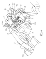
- FIG. 2 an electric toy gun in accordance with the present invention is shown.
- the electric toy gun comprises a primary gun body A and a secondary gun body B (see FIG. 3 ), a trigger 1, a power break holder 2, a power contact holder 3 (see FIG. 4 ), a gearwheel set 4, a swing bar 5, and a control mechanism 6, and a piston set 7 (see FIG. 4 ).
- the trigger 1 (see FIGS. 3 and 4 ) is mounted within the secondary gun body B (see FIG. 2 ), having an axle 11 located at a front side thereof and coupled to a link 12.
- the link 12 has a middle part thereof pivotally coupled to the axle 11, a rear end thereof terminating in a coupling portion 121, and a front end thereof terminating in a stop portion 122.
- the link 12 further comprises an oblong slot 123 formed in the coupling portion 121 and sloping backwardly downwards (see FIG. 4 ).
- the oblong slot 123 is coupled to a push rod 13. If the trigger 1 is not pressed, the coupling portion 121 is lowered (see FIG. 4 ) and the stop portion 122 is lifted.
- the power break holder 2 (see FIGS. 3 and 4 ) is mounted in a holder shell 2' and supported on plural spring members 21 within the holder shell 2'.
- the power break holder 2 can be forced down to compressed the spring members 21 and then returned to its former position by the spring members 21 when the pressure is released from the spring members 21 (see FIGS. 4 and 5 ).
- the power break holder 2 comprises a metal conducting rod 22 downwardly mounted at a bottom side thereof, a block member 23 horizontally slidably coupled to a top side thereof, and a first return spring 24 mounted at the top side and connected to the block member 23 for returning the block member 23 after the block member 23 having be pushed forward.
- the block member 23 comprises a first tooth 231 and a second tooth 232 located at one lateral side thereof, and a protruding rod 234 located at an opposite side thereof (see FIG. 6 ).
- the second tooth 232 is disposed at a front side relative to the first tooth 231.
- the first tooth 231 defines a beveled edge 233 at a front side thereof.
- the power contact holder 3 protrudes over the bottom wall of the holder shell 2 'below the metal conducting rod 22 of the power break holder 2 (see FIGS. 4 and 5 ).
- the metal conducting rod 22 is plugged into the power contact holder 3 to turn on power supply.
- the power break holder 2 is moved upwardly back to its former position, the power is turned off.
- the gearwheel set 4 is a combination of a first gearwheel 41 and a gear train 4'.
- the first gearwheel 41 comprises a gear sector 411 for driving the piston set 7.
- the piston set 7 is immediately returned to its former position, enabling a toy bullet to be fired out of the gun barrel to complete a firing action (this firing action is of the known art, therefore no illustration is provided).
- the first gearwheel 41 comprises a cam 412 at the center of one lateral side thereof.
- the swing bar 5 has a lower part thereof pivotally connected to a fixed point, and a bottom end thereof pressed on the cam 412 of the first gearwheel 41. Therefore, when the first gearwheel 41 rotates through one turn to finish one firing action, the swing bar 5 is driven to complete one swinging cycle (see FIG. 5 ).
- the swing bar 5 comprises an actuation portion 51 located at a top side thereof, a push block 52 slidably coupled to the actuation portion 51, and a second return spring 53 connected between the actuation portion 51 and the push block 52 (see FIGS. 6 and 7 ).
- the block member 23 is disposed at one lateral side of the actuation portion 51 (see FIG. 8 ), and the push block 52 can be disposed at a rear side relative to the first tooth 231 (see FIG. 9 ), or a rear side relative to the second tooth 232 (see FIG. 11 ), or a front side relative to the second tooth 232 (see FIG. 13 ).
- the swing bar 5 further comprises an extension rod 54 extended from the top side thereof. Further, the swing bar 5 has its front side stopped against a third return spring 55 (see FIG. 6 ). After the swing bar 5 has been moved forward, the third return spring 55 immediately pushes the swing bar 5 back to its former position.
- the control mechanism 6 comprises a rotating shaft 61, a connecting rod 62, and a rod holder 63.
- the rotating shaft 61 has a handle 611 provided at one or each of two opposite ends thereof (in the embodiment shown in FIG. 3 , two levers are respectively provided at the two opposite ends of the rotating shaft).
- the connecting rod 62 is pivotally connected to the rotating shaft 61.
- the rod holder 63 is pivotally connected to the connecting rod 62.
- the rod holder 63 comprises a first rod 631 and a second rod 632 respectively downwardly extended from two opposite lateral sides thereof.
- the handle 611 can be selectively biased to a first position P1, a second position P2, or a third position P3 (see FIG. 2 ).
- the first rod 631 pushes the protruding rod 234 to move the block member 23 forward (see FIG. 9 ), and thus, when the power break holder 2 and the block member 23 are lowered, the push block 52 is shifted to the rear side relative to the first tooth 231.
- the handle 611 is biased to the second position P2
- the first rod 631 is shifted to one lateral side relative to the protruding rod 234 (see FIG.
- the push block 52 is shifted to the rear side relative to the second tooth 232.
- the handle 611 is biased to the third position P3
- the first rod 631 is moved backwards without moving the block member 23 (see FIG. 13 )
- the second rod 632 is moved forwards to push the extension rod 54 of the swing bar 5, and thus, when the power break holder 2 and the block member 23 are lowered, the push block 52 is shifted to the front side relative to the second tooth 232.
- the control mechanism 6 can be controlled to adjust the horizontal position of the block member 23.
- the block member 23 can be shifted to one lateral side of the actuation portion 51, and the push block 52 can be shifted to the rear side relative to the first tooth 231 (see FIG. 9 ), the rear side relative to the second tooth 232 (see FIG. 11 ), or the front side relative to the second tooth 232 (see FIG. 13 ), performing the single fire mode, the dual fire mode or the continuous fire mode.
- the link 12 When pressed the trigger 1, the link 12 is forced to lower the block member 23 and the power break holder 2, forcing the power break holder 2 to conduct the power contact holder 3 and to further turn on power supply (see FIG. 5 ).
- the gearwheel set 4 is rotated to conduct a single-shot firing action (single fire mode), causing the swing bar 5 to swing.
- the push block 52 is moved with the actuation portion 51 to push the first tooth 231 (see FIG. 10 ), and the block member 23 is immediately moved forward and released from the downward pressure of the stop portion 122 of the link 12.
- the power break holder 2 is returned by the spring member 21 (see FIGS. 4 and 5 ) and disconnected from the power contact holder 3 to turn off power supply, and thus one cycle of the single fire mode is finished.
- the gearwheel set 4 is rotated to conduct a dual-shot firing action (dual fire mode).
- the swing bar 5 will be forced to swing back and forth.
- the push block 52 is moved with the actuation portion 51 to push the second tooth 232 forward (see FIG. 11 ), causing the block member 23 to move forward.
- the push block 52 is forced by the second return spring 53 to move along the beveled edge 233 to the rear side relative to the first tooth 231 (see FIG. 12 ).
- the first gearwheel 41 is rotated again to cause the swing bar 5 to swing, causing the push block 52 to push the first tooth 231 forward.
- the block member 23 is pushed forward and released from the downward pressure of the stop portion 122 of the link 12 (the block member is moved forward to the position shown in FIG. 10 ), and the power break holder 2 is pushed upwardly away from the power contact holder 3 to turn off power supply, and thus one cycle of the dual fire mode is finished.
- the gearwheel set 4 is rotated to conduct a continuous firing action (continuous fire mode).
- the swing bar 5 will be forced to swing continuously back and forth.
- the electric toy gun of the present invention can be controlled to perform the single fire mode, the dual fire mode or the continuous fire mode, providing a high level of realistic simulation, satisfying the needs of consumers, and enhancing product competitiveness in the global market.
Abstract
Description
- The present invention relates to electric toy gun technology, and more particularly to such an electric toy gun, which provides optional single fire, dual fire and continuous fire modes.
- The driving principle of an electric toy gun is completely different from that of an air-soft toy gun. When the trigger of an electric toy gun is pressed, a power break holder is moved into contact with a power contact holder in the inside of the gun body to start the firing mechanism. Similar designs are seen in Taiwan Patent No.
M389249 US Patent No. 8,146,577 or European Patent No.2,390,614 ) entitled "Electric toy gun with an improved power break control mechanism" and Taiwan Patent No.M395150 US Patent No. 8,091,542 ) entitled "Electric toy gun with a power break control mechanism". When firing, a battery-operatedgearwheel set 10 is driven by a motor to move a piston set 30 toward the rear side in the gun body 20 (seeFIG. 1 ). Thepiston set 30 has areturn spring 301 loaded thereon. When rotating the gearwheel set 10 to a predetermined position, thepiston set 30 is released from the gearwheel set 10, and thereturn spring 301 immediately returns the piston set 30 forwards to its former position, allowing discharge of a compressed gas to drive a toy bullet out of the gun barrel. Thus, one firing action is done, and the toy gun is reset for a next firing action. The above description explains the electric conduction and bullet firing operation of the prior art electric toy gun. - Further, when designing a toy gun, every manufacturer is trying hard to provide a high level of realistic simulation, making the outer appearance of the electric toy gun similar to a real gun. A toy gun can be configured to provide a single fire mode, a continuous fire mode, and a backlash vibration mode. However, no any commercial toy gun is capable of providing a single fire mode, a dual fire mode and a continuous fire mode for selection. Further, among the variously known special toy guns (for example, the pneumatic submachine gun of Taiwan Patent publication No.
201315961 - The present invention has been accomplished under the circumstances in view. It is one object of the present invention to provide an electric toy gun, which has the internal structure thereof so arranged to provide optional single fire, dual fire and continuous fire modes.
- To achieve this and other objects of the present invention, an electric toy gun with optional single fire, dual fire and continuous fire modes of the present invention comprises a trigger coupled, a link, a power break holder, a power contact holder, a gearwheel set, a swing bar and a control mechanism. The link is coupled between the trigger and the power break holder. When the trigger is pressed, the link is forced to move the power break holder into contact with the power contact holder electrically, and at the same time, the gearwheel set is forced to rotate, causing the swing bar to swing back and forth. The swing bar has its top side terminating in an actuation portion. Further, the power break holder is elastically movable back from the power contact holder to its former position to cut off power supply.
- The invention is characterized by the following features. The link comprises a coupling portion and a stop portion. The coupling portion is pivotally connected to the trigger such that when the trigger is pressed by an external force, the coupling portion is lifted, and the stop portion is lowered. Further, the power break holder comprises a block member horizontally slidably coupled to a top side thereof. The block member comprises a first tooth and a second tooth at one lateral side thereof. The second tooth is disposed at a front side relative to the first tooth. The block member is movable downwardly by the stop portion to lower the power break holder into contact with the power contact holder and to further turn on the power supply. The block member is disposed at one lateral side relative to the actuation portion of the swing bar when moved down by the stop portion. The swing bar comprises a push block connected to the actuation portion. The control mechanism is controllable to move the block member in one of three positions, enabling the push block to be selectively shifted to a rear side relative to the first tooth, a rear side relative to the second tooth or a front side relative to the second tooth when the power break holder and the block member are lowered. When the push block is at the rear side relative to the first tooth and the swing bar is moved to push the actuation portion forward, the push block pushes the first tooth forward, causing the block member to be moved forwardly away from the stop portion of the link and the power break holder to be moved away from the power contact holder to turn off the power supply. When the push block is at the rear side relative to the second tooth and the swing bar is moved to push the actuation portion forward, the push block pushes the second tooth, causing the block member to be moved forward and the push block to be forced move to the rear side relative to the first tooth, and the swing bar is moved again to force the push block of the actuation portion to push the first tooth forward, causing the block member to be moved away from the stop portion of the link and the power break holder to be moved away from the power contact holder to turn off the power supply. When the push block is at the front side relative to the second tooth and the swing bar is moved to push the actuation portion forward, the push block is kept away from the first tooth and the second tooth and the actuation portion of the swing bar is continuously moved back and forth, and the coupling portion of the link is lowered and the stop portion is lifted when the trigger is released, and therefore the power break holder is moved upwardly away from the power contact holder to turn off the power supply.
- Further, the block member is disposed above the power break holder. Further, a first return spring is horizontally provided between the block member and the power break holder for enabling the block member to be automatically returned after the block member having been moved forward.
- Further, the first tooth of the block member has a beveled edge located at a front side thereof. Further, a second return spring is provided between the push block and the actuation portion of the swing bar such that when the power break holder and the block member are lowered and the push block is moved to the rear side relative to the second tooth, the push block pushes the second tooth to move the block member forward, and then the second return spring forces the push block to move along the beveled edge to the rear side relative to the first tooth.
- Further, the control mechanism comprises a rotating shaft, a connecting rod and a rod holder. The rotating shaft comprises a handle at least one of two opposite ends thereof. The connecting rod is pivotally connected to the rotating shaft. The rod holder is pivotally connected to the connecting rod. The rod holder comprises a first rod and a second rod respectively downwardly extended from two opposite lateral sides thereof. The rotating shaft is rotatable by the handle to move the connecting rod in rotating the rod holder to reverse the position of the first rod and the position of the second rod. The handle is selectively movable to a first position, a second position and a third position.
- Further, the block member comprises a protruding rod. When the handle of the control mechanism is moved to the first position, the first rod is forced against the protruding rod to move the block member forward, enabling the push block to be moved to the rear side relative to the first tooth when the power break holder and the block member are lowered. When the handle of the control mechanism is moved to the second position, the first rod is disposed at one lateral side relative to the protruding rod and the block member is immovable, and therefore the push block is moved to the rear side of the second tooth when the power break holder and the block member are lowered.
- Further, the block member comprises a protruding rod. The swing bar comprises an extension rod at a top side thereof. When the handle of the control mechanism is moved to the third position, the first rod is moved backwardly away from the protruding rod, the block member is immovable, and the second rod is forced against the extension rod to move the swing bar forward, enabling the push block to be moved to the front side relative to the second tooth when the power break holder and the block member are lowered.
- In another embodiment of the present invention, the electric toy gun comprises a trigger, a power break holder, a power contact holder, a gearwheel set, a swing bar, and a link movable by the trigger to push the power break holder into contact with the power contact holder and to further turn on a power supply. The gearwheel set is rotated to cause the swing bar to swing when the power supply is turned on. The swing bar comprises an actuation portion at a top side thereof. The power break holder is movable away from the power contact holder to turn off the power supply. Further, the link comprises a coupling portion and a stop portion. The coupling portion is pivotally connected to the trigger such that when the trigger is pressed by an external force, the coupling portion is lifted, and the stop portion is lowered. Further, the power break holder comprises a block member horizontally slidably coupled to a top side thereof. The block member comprises a first tooth at one lateral side thereof. The block member is movable downwardly by the stop portion to lower the power break holder into contact with the power contact holder and to further turn on the power supply. The block member is disposed at one lateral side relative to the actuation portion of the swing bar when lowered. Further, the swing bar comprises a push block connected to the actuation portion and disposed at a rear side relative to the first tooth. The push block is forced against the first tooth to move the block member forwardly away from the stop portion of the link for enabling the power break holder to be moved away from the power contact holder to turn off the power supply when the swing bar is moved to push the actuation portion forward.
- In still another embodiment of the present invention, the electric toy gun comprises a trigger, a power break holder, a power contact holder, a gearwheel set, a swing bar, and a link movable by the trigger to push the power break holder into contact with the power contact holder and to further turn on a power supply. The gearwheel set is rotated to cause the swing bar to swing when the power supply is turned on. The swing bar comprises an actuation portion at a top side thereof. The power break holder is movable away from the power contact holder to turn off the power supply. Further, the link comprises a coupling portion and a stop portion. The coupling portion is pivotally connected to the trigger such that when the trigger is pressed by an external force, the coupling portion is lifted, and the stop portion is lowered. Further, the power break holder comprises a block member horizontally slidably coupled to a top side thereof. The block member comprises a first tooth and a second tooth disposed at one lateral side thereof. The second tooth is disposed at a front side relative to the first tooth. The block member is movable downwardly by the stop portion to lower the power break holder into contact with the power contact holder and to further turn on the power supply. The block member is disposed at one lateral side relative to the actuation portion of the swing bar when lowered. Further, the swing bar comprises a push block connected to the actuation portion and disposed at a rear side relative to the second tooth. The push block is forced against the second tooth to move the block member forward when the swing bar is forced to move the actuation portion forward, and the push block is moved to the rear side relative to the first tooth after forward movement of the block member, and the swing bar is moved to force the push block against the first tooth in moving the block member away from the stop portion of the link, enabling the power break holder to be moved away from the power contact holder to further turn off the power supply.
- In still another embodiment of the present invention, the electric toy gun comprises a trigger, a power break holder, a power contact holder, a gearwheel set, a swing bar, and a link movable by the trigger to push the power break holder into contact with the power contact holder and to further turn on a power supply. The gearwheel set is rotated to cause the swing bar to swing when the power supply is turned on. The swing bar comprises an actuation portion at a top side thereof. The power break holder is movable away from the power contact holder to turn off the power supply. Further, the link comprises a coupling portion and a stop portion. The coupling portion is pivotally connected to the trigger such that when the trigger is pressed by an external force, the coupling portion is lifted, and the stop portion is lowered. Further, the power break holder comprises a block member horizontally slidably coupled to a top side thereof. The block member comprising a first tooth and a second tooth disposed at one lateral side thereof. The second tooth is disposed at a front side relative to the first tooth. The block member is movable downwardly by the stop portion to lower the power break holder into contact with the power contact holder and to further turn on the power supply. The block member is disposed at one lateral side relative to the actuation portion of the swing bar when lowered. Further, the swing bar comprises a push block connected to the actuation portion and disposed at a front side relative to the second tooth. When the swing bar is driven to move the actuation portion forward, the push block is kept away from the first tooth and the second tooth, and the actuation portion of the swing bar is continuously moved back and forth, and when said trigger is released, said coupling portion of said link is lowered and said stop portion is lifted, causing said power break holder to be moved upwardly away from said power contact holder to turn off said power supply.
- Preferably, the block member is disposed above the power break holder, and a first return spring is horizontally connected between the block member and the power break holder for enabling the block member to be automatically returned after having been moved forward.
- Preferably, the first tooth of the block member has a beveled edge located at a front side thereof, and a second return spring is provided between the push block and the actuation portion of the swing bar. Thus, when the power break holder and the block member are lowered and the push block is moved to the rear side relative to the second tooth, the push block pushes the second tooth to move the block member forward, and then the second return spring forces the push block to move along the beveled edge to the rear side relative to the first tooth.
- Thus, subject to the aforesaid arrangement of the trigger, the power break holder, the power contact holder, the gearwheel set, the swing bar and the control mechanism, the electric toy gun can be selected to perform the single fire mode, the dual fire mode, or the continuous fire mode, providing a high level of realistic simulation, satisfying the needs of consumers, and enhancing product competitiveness in the global market.
- The other object of this invention is subject to the aforesaid arrangement of the trigger, the power break holder, the power contact holder, the gearwheel set and the swing bar, the electric toy gun can be single to perform the single fire mode, the dual fire mode, or the continuous fire mode, providing a high level of realistic simulation, satisfying the needs of consumers, and enhancing product competitiveness in the global market.
-
-
FIG. 1 is a structural plain view of a driving structure of an electric toy gun according to the prior art. -
FIG. 2 is a schematic plain view of an electric toy gun in accordance with the present invention. -
FIG. 3 is an exploded view of the major part of the electric toy gun in accordance with the present invention. -
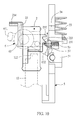
FIG. 4 is a plain view of the assembly shown inFIG. 3 . -
FIG. 5 corresponds toFIG. 4 , illustrating the trigger pressed. -
FIG. 6 is an enlarged scale of a part ofFIG. 3 and showing the other side view. -
FIG. 7 is a schematic structural plain view of the present invention, illustrating the trigger immovable. -
FIG. 8 corresponds toFIG. 7 , illustrating the trigger pressed. -
FIG. 9 is a schematic top view of the block member and push block of the electric toy gun in accordance with the present invention during the single fire mode. -
FIG. 10 corresponds toFIG. 9 , illustrating the block member moved forward. -
FIG. 11 is a schematic top view of the block member and push block of the electric toy gun in accordance with the present invention during the first shot under the dual fire mode. -
FIG. 12 corresponds toFIG. 11 when in the second shot under the dual fire mode. -
FIG. 13 is a schematic top view of the block member and push block of the electric toy gun in accordance with the present invention during the continuous fire mode. - Referring to
FIG. 2 , an electric toy gun in accordance with the present invention is shown. - Referring to
FIGS. 3 and4 andFIG. 2 again, the electric toy gun comprises a primary gun body A and a secondary gun body B (seeFIG. 3 ), atrigger 1, apower break holder 2, a power contact holder 3 (seeFIG. 4 ), agearwheel set 4, aswing bar 5, and acontrol mechanism 6, and a piston set 7 (seeFIG. 4 ). - The trigger 1 (see
FIGS. 3 and4 ) is mounted within the secondary gun body B (seeFIG. 2 ), having anaxle 11 located at a front side thereof and coupled to alink 12. Thelink 12 has a middle part thereof pivotally coupled to theaxle 11, a rear end thereof terminating in acoupling portion 121, and a front end thereof terminating in astop portion 122. Thelink 12 further comprises anoblong slot 123 formed in thecoupling portion 121 and sloping backwardly downwards (seeFIG. 4 ). Theoblong slot 123 is coupled to apush rod 13. If thetrigger 1 is not pressed, thecoupling portion 121 is lowered (seeFIG. 4 ) and thestop portion 122 is lifted. On the contrary, if thetrigger 1 is pressed, thepush rod 13 is moved backwards along theoblong slot 123, causing thecoupling portion 121 of thelink 12 to be lifted (seeFIG. 5 ) and thestop portion 122 to be lowered. - The power break holder 2 (see
FIGS. 3 and4 ) is mounted in aholder shell 2' and supported onplural spring members 21 within theholder shell 2'. Thus, thepower break holder 2 can be forced down to compressed thespring members 21 and then returned to its former position by thespring members 21 when the pressure is released from the spring members 21 (seeFIGS. 4 and5 ). Further, thepower break holder 2 comprises ametal conducting rod 22 downwardly mounted at a bottom side thereof, ablock member 23 horizontally slidably coupled to a top side thereof, and afirst return spring 24 mounted at the top side and connected to theblock member 23 for returning theblock member 23 after theblock member 23 having be pushed forward. Theblock member 23 comprises afirst tooth 231 and asecond tooth 232 located at one lateral side thereof, and a protrudingrod 234 located at an opposite side thereof (seeFIG. 6 ). Thesecond tooth 232 is disposed at a front side relative to thefirst tooth 231. Further, thefirst tooth 231 defines abeveled edge 233 at a front side thereof. When thestop portion 122 of thelink 12 is lowered, it forces theblock member 23 and thepower break holder 2 downwards (seeFIG. 5 ). - The
power contact holder 3 protrudes over the bottom wall of the holder shell 2'below themetal conducting rod 22 of the power break holder 2 (seeFIGS. 4 and5 ). Thus, when theblock member 23 and thepower break holder 2 are lowered, themetal conducting rod 22 is plugged into thepower contact holder 3 to turn on power supply. On the contrary, when thepower break holder 2 is moved upwardly back to its former position, the power is turned off. - The gearwheel set 4 is a combination of a
first gearwheel 41 and a gear train 4'. Thefirst gearwheel 41 comprises agear sector 411 for driving thepiston set 7. When thefirst gearwheel 41 is rotated to the position where thegear sector 411 is disengaged from the piston set 7, the piston set 7 is immediately returned to its former position, enabling a toy bullet to be fired out of the gun barrel to complete a firing action (this firing action is of the known art, therefore no illustration is provided). As soon as thefirst gearwheel 41 is rotated to the position where thegear sector 411 is forced into engagement with the piston set 7 again, a next firing action is ready. Further, thefirst gearwheel 41 comprises acam 412 at the center of one lateral side thereof. - The
swing bar 5 has a lower part thereof pivotally connected to a fixed point, and a bottom end thereof pressed on thecam 412 of thefirst gearwheel 41. Therefore, when thefirst gearwheel 41 rotates through one turn to finish one firing action, theswing bar 5 is driven to complete one swinging cycle (seeFIG. 5 ). Theswing bar 5 comprises anactuation portion 51 located at a top side thereof, apush block 52 slidably coupled to theactuation portion 51, and asecond return spring 53 connected between theactuation portion 51 and the push block 52 (seeFIGS. 6 and7 ). When thestop portion 122 of thelink 12 is lowered to force theblock member 23 and thepower break holder 2 downwards, theblock member 23 is disposed at one lateral side of the actuation portion 51 (seeFIG. 8 ), and thepush block 52 can be disposed at a rear side relative to the first tooth 231 (seeFIG. 9 ), or a rear side relative to the second tooth 232 (seeFIG. 11 ), or a front side relative to the second tooth 232 (seeFIG. 13 ). Theswing bar 5 further comprises anextension rod 54 extended from the top side thereof. Further, theswing bar 5 has its front side stopped against a third return spring 55 (seeFIG. 6 ). After theswing bar 5 has been moved forward, thethird return spring 55 immediately pushes theswing bar 5 back to its former position. - The
control mechanism 6 comprises arotating shaft 61, a connectingrod 62, and arod holder 63. The rotatingshaft 61 has ahandle 611 provided at one or each of two opposite ends thereof (in the embodiment shown inFIG. 3 , two levers are respectively provided at the two opposite ends of the rotating shaft). The connectingrod 62 is pivotally connected to therotating shaft 61. Therod holder 63 is pivotally connected to the connectingrod 62. Therod holder 63 comprises afirst rod 631 and asecond rod 632 respectively downwardly extended from two opposite lateral sides thereof. When biasing onehandle 611 to rotate therotating shaft 61, the connectingrod 62 will be forced to move therod holder 63, thereby reversely biasing thefirst rod 631 and thesecond rod 632. Further, thehandle 611 can be selectively biased to a first position P1, a second position P2, or a third position P3 (seeFIG. 2 ). When thehandle 611 is biased to the first position P1, thefirst rod 631 pushes the protrudingrod 234 to move theblock member 23 forward (seeFIG. 9 ), and thus, when thepower break holder 2 and theblock member 23 are lowered, thepush block 52 is shifted to the rear side relative to thefirst tooth 231. When thehandle 611 is biased to the second position P2, thefirst rod 631 is shifted to one lateral side relative to the protruding rod 234 (seeFIG. 11 ) without moving theblock member 23, and thus, when thepower break holder 2 and theblock member 23 are lowered, thepush block 52 is shifted to the rear side relative to thesecond tooth 232. When thehandle 611 is biased to the third position P3, thefirst rod 631 is moved backwards without moving the block member 23 (seeFIG. 13 ), and thesecond rod 632 is moved forwards to push theextension rod 54 of theswing bar 5, and thus, when thepower break holder 2 and theblock member 23 are lowered, thepush block 52 is shifted to the front side relative to thesecond tooth 232. Thus, thecontrol mechanism 6 can be controlled to adjust the horizontal position of theblock member 23. - By means of selectively biasing the
handle 611 of thecontrol mechanism 6 to the first position P1, the second position P2 or the third position P3(seeFIG. 2 ) and then pressing thetrigger 1 to lower thepower break holder 2 and theblock member 23, theblock member 23 can be shifted to one lateral side of theactuation portion 51, and thepush block 52 can be shifted to the rear side relative to the first tooth 231 (seeFIG. 9 ), the rear side relative to the second tooth 232 (seeFIG. 11 ), or the front side relative to the second tooth 232 (seeFIG. 13 ), performing the single fire mode, the dual fire mode or the continuous fire mode. - The operation of the single fire mode, the dual fire mode and the continuous fire mode are outlined thereinafter.
- When pressed the
trigger 1, thelink 12 is forced to lower theblock member 23 and thepower break holder 2, forcing thepower break holder 2 to conduct thepower contact holder 3 and to further turn on power supply (seeFIG. 5 ). If thepush block 52 is at the rear side relative to thefirst tooth 231 at this time (seeFIG. 9 ), the gearwheel set 4 is rotated to conduct a single-shot firing action (single fire mode), causing theswing bar 5 to swing. At the moment theswing bar 5 swings forward, thepush block 52 is moved with theactuation portion 51 to push the first tooth 231 (seeFIG. 10 ), and theblock member 23 is immediately moved forward and released from the downward pressure of thestop portion 122 of thelink 12. Thereafter, thepower break holder 2 is returned by the spring member 21 (seeFIGS. 4 and5 ) and disconnected from thepower contact holder 3 to turn off power supply, and thus one cycle of the single fire mode is finished. - Further, if the
push block 52 is at the rear side relative to the second tooth 232 (seeFIG. 11 ) when theblock member 23 and thepower break holder 2 are lowered to the position where thepower break holder 2 touches thepower contact holder 3 to turn on power supply (seeFIG. 5 ), the gearwheel set 4 is rotated to conduct a dual-shot firing action (dual fire mode). When the gearwheel set 4 is rotated at this time, theswing bar 5 will be forced to swing back and forth. When theswing bar 5 swings forward (to initiate a primary firing action), thepush block 52 is moved with theactuation portion 51 to push thesecond tooth 232 forward (seeFIG. 11 ), causing theblock member 23 to move forward. After forward displacement of theblock member 23, thepush block 52 is forced by thesecond return spring 53 to move along thebeveled edge 233 to the rear side relative to the first tooth 231 (seeFIG. 12 ). Thereafter, thefirst gearwheel 41 is rotated again to cause theswing bar 5 to swing, causing thepush block 52 to push thefirst tooth 231 forward. At this time, theblock member 23 is pushed forward and released from the downward pressure of thestop portion 122 of the link 12 (the block member is moved forward to the position shown inFIG. 10 ), and thepower break holder 2 is pushed upwardly away from thepower contact holder 3 to turn off power supply, and thus one cycle of the dual fire mode is finished. - Further, if the
push block 52 is at the front side relative to the second tooth 232 (seeFIG. 13 ) when theblock member 23 and thepower break holder 2 are lowered to the position where thepower break holder 2 touches thepower contact holder 3 to turn on power supply (seeFIG. 5 ), the gearwheel set 4 is rotated to conduct a continuous firing action (continuous fire mode). When the gearwheel set 4 is rotated at this time, theswing bar 5 will be forced to swing continuously back and forth. When theactuation portion 51 moves forward during swinging of theswing bar 5, thepush block 52 does not push thefirst tooth 231 and thesecond tooth 232, and therefore the gearwheel set 4 keeps rotating, causing theactuation portion 51 of theswing bar 5 to continuously move back and forth, and toy bullets are continuously fired. When the user releases thetrigger 1, thestop portion 122 of thelink 12 is lifted, causing thepower break holder 2 to be moved upwardly away from thepower contact holder 3, and therefore the power supply is turned off. - As stated above, subject to proper arrangement of the
trigger 1, thepower break holder 2, thepower contact holder 3, the gearwheel set 4 and theswing bar 5 and the control of thecontrol mechanism 6, the electric toy gun of the present invention can be controlled to perform the single fire mode, the dual fire mode or the continuous fire mode, providing a high level of realistic simulation, satisfying the needs of consumers, and enhancing product competitiveness in the global market. - Although a particular embodiment of the invention has been described in detail for purposes of illustration, various modifications and enhancements may be made without departing from the scope of the invention. Accordingly, the invention is not to be limited except as by the appended claims.
Claims (12)
- An electric toy gun, comprising a trigger (1), a power break holder (2), a power contact holder (3), a gearwheel set (4), a swing bar (5), a control mechanism (6), and a link (12) movable by said trigger (1) to push said power break holder (2) into contact with said power contact holder (3) and to further turn on a power supply, said gearwheel set (4) being rotated to cause said swing bar (5) to swing when said power supply is turned on, said swing bar (5) comprising an actuation portion (51) at a top side thereof, said power break holder (2) being movable away from said power contact holder (3) to turn off said power supply, wherein:said link (12) comprises a coupling portion (121) and a stop portion (122), said coupling portion (121) being pivotally connected to said trigger (1) such that when said trigger (1) is pressed by an external force, said coupling portion (121) is lifted, and said stop portion (122) is lowered;said power break holder (2) comprises a block member (23) horizontally slidably coupled to a top side thereof, said block member (23) comprising a first tooth (231) and a second tooth (232) at one lateral side thereof, said second tooth (232) being disposed at a front side relative to said first tooth (231), said block member (23) being movable downwardly by said stop portion (122) to lower said power break holder (2) into contact with said power contact holder (3) and to further turn on said power supply, said block member (23) being disposed at one lateral side relative to said actuation portion (51) of said swing bar (5) when moved down by said stop portion (122); said swing bar (5) comprises a push block (52) connected to said actuation portion (51); said control mechanism (6) is controllable to move said block member (23) in one of three positions, enabling said push block (52) to be selectively shifted to a rear side relative to said first tooth (231), a rear side relative to said second tooth (232) or a front side relative to said second tooth (232) when said power break holder (2) and said block member (23) are lowered; when said push block (52) is at the rear side relative to said first tooth (231) and said swing bar (5) is moved to push said actuation portion (51) forward, said push block (52) pushes said first tooth (231) forward, causing said block member (23) to be moved forwardly away from said stop portion (122) of said link (12) and said power break holder (2) to be moved away from said power contact holder (3) to turn off said power supply; when said push block (52) is at the rear side relative to said second tooth (232) and said swing bar (5) is moved to push said actuation portion (51) forward, said push block (52) pushes said second tooth (232), causing said block member (23) to be moved forward and said push block (52) to be forced move to the rear side relative to said first tooth (231), and said swing bar (5) is moved again to force said push block (52) of said actuation portion (51) to push said first tooth (231) forward, causing said block member (23) to be moved away from said stop portion (122) of said link (12) and said power break holder (2) to be moved away from said power contact holder (3) to turn off said power supply; when said push block (52) is at the front side relative to said second tooth (232) and said swing bar (5) is moved to push said actuation portion (51) forward, said push block (52) is kept away from said first tooth (231) and said second tooth (232) and said actuation portion (51) of said swing bar (5) is continuously moved back and forth, and said coupling portion (121) of said link (12) is lowered and said stop portion (122) is lifted when said trigger (1) is released, and therefore said power break holder (2) is moved upwardly away from said power contact holder (3) to turn off said power supply.
- The electric toy gun as claimed in claim 1, wherein said block member (23) is disposed above said power break holder (2); a first return spring (24) is horizontally provided between said block member (23) and said power break holder (2) for enabling said block member (23) to be automatically returned after said block member (23) having been moved forward.
- The electric toy gun as claimed in claim 2, wherein said first tooth (231) of said block member (23) has a beveled edge (233) located at a front side thereof; a second return spring (53) is provided between said push block (52) and said actuation portion (51) of said swing bar (5) such that when said power break holder (2) and said block member (23) are lowered and said push block (52) is moved to the rear side relative to said second tooth (232), said push block (52) pushes said second tooth (232) to move said block member (23) forward, and then said second return spring (53) forces said push block (52) to move along said beveled edge (233) to the rear side relative to said first tooth (231).
- The electric toy gun as claimed in claim 3, wherein said control mechanism (6) comprises a rotating shaft (61), a connecting rod (62) and a rod holder (63), said rotating shaft (61) comprises a handle (611) at least one of two opposite ends thereof, said connecting rod (62) being pivotally connected to said rotating shaft (61), said rod holder (63) being pivotally connected to said connecting rod (62), said rod holder (63) comprising a first rod (631) and a second rod (632) respectively downwardly extended from two opposite lateral sides thereof, said rotating shaft (61) being rotatable by said handle (611) to move said connecting rod (62) in rotating said rod holder (63) to reverse the position of said first rod (631) and the position of said second rod (632), said handle (611) being selectively movable to a first position (P1), a second position (P2) and a third position (P3).
- The electric toy gun as claimed in claim 4, wherein said block member (23) comprises a protruding rod (234); when said handle (611) of said control mechanism (6) is moved to said first position (P1), said first rod (631) is forced against said protruding rod (234) to move said block member (23) forward, enabling said push block (52) to be moved to the rear side relative to said first tooth (231) when said power break holder (2) and said block member (23) are lowered.
- The electric toy gun as claimed in claim 4, wherein said block member (23) comprises a protruding rod (234); when said handle (611) of said control mechanism (6) is moved to said second position (P2), said first rod (631) is disposed at one lateral side relative to said protruding rod (234) and said block member (23) is immovable, and therefore said push block (52) is moved to the rear side of said second tooth (232) when said power break holder (2) and said block member (23) are lowered.
- The electric toy gun as claimed in claim 1, wherein said block member (23) comprises a protruding rod (234); said swing bar (5) comprises an extension rod (54) at a top side thereof; when said handle (611) of said control mechanism (6) is moved to said third position (P3), said first rod (631) is moved backwardly away from said protruding rod (234), said block member (23) is immovable, and said second rod (632) is forced against said extension rod (54) to move said swing bar (5) forward, enabling said push block (52) to be moved to the front side relative to said second tooth (232) when said power break holder (2) and said block member (23) are lowered.
- An electric toy gun, comprising a trigger (1), a power break holder (2), a power contact holder (3), a gearwheel set (4), a swing bar (5), and a link (12) movable by said trigger (1) to push said power break holder (2) into contact with said power contact holder (3) and to further turn on a power supply, said gearwheel set (4) being rotated to cause said swing bar (5) to swing when said power supply is turned on, said swing bar (5) comprising an actuation portion (51) at a top side thereof, said power break holder (2) being movable away from said power contact holder (3) to turn off said power supply, wherein:said link (12) comprises a coupling portion (121) and a stop portion (122), said coupling portion (121) being pivotally connected to said trigger (1) such that when said trigger (1) is pressed by an external force, said coupling portion (121) is lifted, and said stop portion (122) is lowered;said power break holder (2) comprises a block member (23) horizontally slidably coupled to a top side thereof, said block member (23) comprising a first tooth (231) at one lateral side thereof, said block member (23) being movable downwardly by said stop portion (122) to lower said power break holder (2) into contact with said power contact holder (3) and to further turn on said power supply, said block member (23) being disposed at one lateral side relative to said actuation portion (51) of said swing bar (5) when lowered;said swing bar (5) comprises a push block (52) connected to said actuation portion (51) and disposed at a rear side relative to said first tooth (231), said push block (52) being forced against said first tooth (231) to move said block member (23) forwardly away from said stop portion (122) of said link (12) for enabling said power break holder (2) to be moved away from said power contact holder (3) to turn off said power supply when said swing bar (5) is moved to push said actuation portion (51) forward.
- An electric toy gun, comprising a trigger (1), a power break holder (2), a power contact holder (3), a gearwheel set (4), a swing bar (5), and a link (12) movable by said trigger (1) to push said power break holder (2) into contact with said power contact holder (3) and to further turn on a power supply, said gearwheel set (4) being rotated to cause said swing bar (5) to swing when said power supply is turned on, said swing bar (5) comprising an actuation portion (51) at a top side thereof, said power break holder (2) being movable away from said power contact holder (3) to turn off said power supply, wherein:said link (12) comprises a coupling portion (121) and a stop portion (122), said coupling portion (121) being pivotally connected to said trigger (1) such that when said trigger (1) is pressed by an external force, said coupling portion (121) is lifted, and said stop portion (122) is lowered;said power break holder (2) comprises a block member (23) horizontally slidably coupled to a top side thereof, said block member (23) comprising a first tooth (231) and a second tooth (232) disposed at one lateral side thereof, said second tooth (232) being disposed at a front side relative to said first tooth (231), said block member (23) being movable downwardly by said stop portion (122) to lower said power break holder (2) into contact with said power contact holder (3) and to further turn on said power supply, said block member (23) being disposed at one lateral side relative to said actuation portion (51) of said swing bar (5) when lowered;said swing bar (5) comprises a push block (52) connected to said actuation portion (51) and disposed at a rear side relative to said second tooth (232); said push block (52) is forced against said second tooth (232) to move said block member (23) forward when said swing bar (5) is forced to move said actuation portion (51) forward, and said push block (52) is moved to the rear side relative to said first tooth (231) after forward movement of said block member (23), and said swing bar (5) is moved to force said push block (52) against said first tooth (231) in moving said block member (23) away from said stop portion (122) of said link (12), enabling said power break holder (2) to be moved away from said power contact holder (3) to further turn off said power supply.
- An electric toy gun, comprising a trigger (1), a power break holder (2), a power contact holder (3), a gearwheel set (4), a swing bar (5), and a link (12) movable by said trigger (1) to push said power break holder (2) into contact with said power contact holder (3) and to further turn on a power supply, said gearwheel set (4) being rotated to cause said swing bar (5) to swing when said power supply is turned on, said swing bar (5) comprising an actuation portion (51) at a top side thereof, said power break holder (2) being movable away from said power contact holder (3) to turn off said power supply, wherein:said link (12) comprises a coupling portion (121) and a stop portion (122), said coupling portion (121) being pivotally connected to said trigger (1) such that when said trigger (1) is pressed by an external force, said coupling portion (121) is lifted, and said stop portion (122) is lowered;said power break holder (2) comprises a block member (23) horizontally slidably coupled to a top side thereof, said block member (23) comprising a first tooth (231) and a second tooth (232) disposed at one lateral side thereof, said second tooth (232) being disposed at a front side relative to said first tooth (231), said block member (23) being movable downwardly by said stop portion (122) to lower said power break holder (2) into contact with said power contact holder (3) and to further turn on said power supply, said block member (23) being disposed at one lateral side relative to said actuation portion (51) of said swing bar (5) when lowered;said swing bar (5) comprises a push block (52) connected to said actuation portion (51) and disposed at a front side relative to said second tooth (232); when said swing bar (5) is driven to move said actuation portion (51) forward, said push block (52) is kept away from said first tooth (231) and said second tooth (232), and said actuation portion (51) of said swing bar (5) is continuously moved back and forth, and when said trigger (1) is released, said coupling portion (121) of said link (12) is lowered and said stop portion (122) is lifted, causing said power break holder (2) to be moved upwardly away from said power contact holder (3) to turn off said power supply.
- The electric toy gun as claimed in claim 8, 9 or 10, wherein said block member (23) is disposed above said power break holder (2), and a first return spring (24) is horizontally connected between said block member (23) and said power break holder (2) for enabling said block member (23) to be automatically returned after having been moved forward.
- The electric toy gun as claimed in claim 9, wherein said block member (23) is disposed above said power break holder (2), and a first return spring (24) is horizontally connected between said block member (23) and said power break holder (2) for enabling said block member (23) to be automatically returned after having been moved forward; said first tooth (231) of said block member (23) has a beveled edge (233) located at a front side thereof; a second return spring (53) is provided between said push block (52) and said actuation portion (51) of said swing bar (5) such that when said power break holder (2) and said block member (23) are lowered and said push block (52) is moved to the rear side relative to said second tooth (232), said push block (52) pushes said second tooth (232) to move said block member (23) forward, and then said second return spring (53) forces said push block (52) to move along said beveled edge (233) to the rear side relative to said first tooth (231).
Applications Claiming Priority (1)
| Application Number | Priority Date | Filing Date | Title |
|---|---|---|---|
| TW102117159A TWI521182B (en) | 2013-05-15 | 2013-05-15 | Electric toy gun |
Publications (2)
| Publication Number | Publication Date |
|---|---|
| EP2803937A2 true EP2803937A2 (en) | 2014-11-19 |
| EP2803937A3 EP2803937A3 (en) | 2014-12-10 |
Family
ID=49000880
Family Applications (1)
| Application Number | Title | Priority Date | Filing Date |
|---|---|---|---|
| EP13250089.3A Withdrawn EP2803937A3 (en) | 2013-05-15 | 2013-07-30 | Electric toy gun |
Country Status (3)
| Country | Link |
|---|---|
| US (1) | US9022014B2 (en) |
| EP (1) | EP2803937A3 (en) |
| TW (1) | TWI521182B (en) |
Cited By (1)
| Publication number | Priority date | Publication date | Assignee | Title |
|---|---|---|---|---|
| EP3276295A4 (en) * | 2015-03-24 | 2018-10-31 | Tokyo Marui Co.Ltd. | Cut-off device of electric mechanism in imitation gun |
Families Citing this family (1)
| Publication number | Priority date | Publication date | Assignee | Title |
|---|---|---|---|---|
| TWM535314U (en) * | 2016-05-13 | 2017-01-11 | Guay Guay Trading Co Ltd | Power regulating device of toy gun |
Citations (5)
| Publication number | Priority date | Publication date | Assignee | Title |
|---|---|---|---|---|
| TWM389249U (en) | 2010-01-18 | 2010-09-21 | Yih Kai Enterprise Co Ltd | Power-interruption unit of electrical toy gun |
| TWM395150U (en) | 2010-05-21 | 2010-12-21 | Yih Kai Entpr Co Ltd | Power break device for electric toy gun |
| EP2390614A1 (en) | 2010-05-27 | 2011-11-30 | Yih Kai Enterprise Co., Ltd | Electric toy gun with an improved power break control mechanism |
| US8146577B2 (en) | 2010-02-10 | 2012-04-03 | Shih-Che Hu | Electric toy gun with an improved power break control mechanism |
| TW201315961A (en) | 2011-10-07 | 2013-04-16 | Yih Kai Entpr Co Ltd | Percussion linkage unit of toy submachine gun |
Family Cites Families (11)
| Publication number | Priority date | Publication date | Assignee | Title |
|---|---|---|---|---|
| US2548622A (en) * | 1946-08-14 | 1951-04-10 | Frederick W Sampson | Firing mechanism for submachine guns |
| US2896604A (en) * | 1955-11-07 | 1959-07-28 | Rebikoff Dimitri Issaiewitch | Underwater gun |
| US3026640A (en) * | 1959-03-09 | 1962-03-27 | Ernest B Ogdon | Toy guns |
| US5184756A (en) * | 1991-07-18 | 1993-02-09 | Talk To Me Products, Inc. | Flywheel water gun |
| WO2005066575A1 (en) * | 2003-12-26 | 2005-07-21 | Koichi Tsurumoto | Air gun and number-of-shots change control method |
| US7077117B1 (en) * | 2004-12-29 | 2006-07-18 | Chen-Tang Chu | Detachable driving assembly for a toy gun |
| TWI264518B (en) * | 2005-06-24 | 2006-10-21 | Unicorn Hobby Corp | Controlling structure of double acting toy gun |
| US7578227B1 (en) * | 2007-04-23 | 2009-08-25 | The United States Of America As Represented By The Secretary Of The Army | Fire control mechanism for selectable fire |
| US7971583B2 (en) * | 2008-11-07 | 2011-07-05 | I Chih Shivan Enterprise Co., Ltd. | Fire control device and method for a toy gun |
| US8146576B2 (en) * | 2010-01-19 | 2012-04-03 | Shih-Che Hu | Firing actuator mechanism for toy gun |
| US8549982B2 (en) * | 2010-12-10 | 2013-10-08 | Stephen P. Troy, Jr. | Firearm control devices |
-
2013
- 2013-05-15 TW TW102117159A patent/TWI521182B/en not_active IP Right Cessation
- 2013-07-30 EP EP13250089.3A patent/EP2803937A3/en not_active Withdrawn
- 2013-08-12 US US13/964,224 patent/US9022014B2/en not_active Expired - Fee Related
Patent Citations (6)
| Publication number | Priority date | Publication date | Assignee | Title |
|---|---|---|---|---|
| TWM389249U (en) | 2010-01-18 | 2010-09-21 | Yih Kai Enterprise Co Ltd | Power-interruption unit of electrical toy gun |
| US8146577B2 (en) | 2010-02-10 | 2012-04-03 | Shih-Che Hu | Electric toy gun with an improved power break control mechanism |
| TWM395150U (en) | 2010-05-21 | 2010-12-21 | Yih Kai Entpr Co Ltd | Power break device for electric toy gun |
| US8091542B2 (en) | 2010-05-21 | 2012-01-10 | Shih-Che Hu | Electric toy gun with a power break control mechanism |
| EP2390614A1 (en) | 2010-05-27 | 2011-11-30 | Yih Kai Enterprise Co., Ltd | Electric toy gun with an improved power break control mechanism |
| TW201315961A (en) | 2011-10-07 | 2013-04-16 | Yih Kai Entpr Co Ltd | Percussion linkage unit of toy submachine gun |
Cited By (1)
| Publication number | Priority date | Publication date | Assignee | Title |
|---|---|---|---|---|
| EP3276295A4 (en) * | 2015-03-24 | 2018-10-31 | Tokyo Marui Co.Ltd. | Cut-off device of electric mechanism in imitation gun |
Also Published As
| Publication number | Publication date |
|---|---|
| US20140338648A1 (en) | 2014-11-20 |
| TW201443386A (en) | 2014-11-16 |
| EP2803937A3 (en) | 2014-12-10 |
| TWI521182B (en) | 2016-02-11 |
| US9022014B2 (en) | 2015-05-05 |
Similar Documents
| Publication | Publication Date | Title |
|---|---|---|
| JP3118822U (en) | Double-acting toy gun control structure | |
| US8800541B2 (en) | Electric toy gun | |
| US8091542B2 (en) | Electric toy gun with a power break control mechanism | |
| US8662063B2 (en) | Electric toy gun with an attached cartridge carrier | |
| JP3147056U (en) | Motion control mechanism of electric toy gun | |
| US7946283B2 (en) | Toy gun mechanism with a sliding bolt assembly | |
| EP2113736B1 (en) | Recoil shock device in toy gun | |
| US8297269B2 (en) | Gun bolt transmission mechanism for electric toy gun | |
| US8146577B2 (en) | Electric toy gun with an improved power break control mechanism | |
| US8585407B2 (en) | Toy gun backlash vibration mechanism | |
| KR20170074287A (en) | Play gun | |
| EP2816308A2 (en) | Firearm firing system | |
| EP3276297B1 (en) | Multiple bullet firing-type electric gun | |
| EP2390614B1 (en) | Electric toy gun with an improved power break control mechanism | |
| US9022014B2 (en) | Electric toy gun | |
| JP2010025501A (en) | Mechanical energization interrupting device in electric gun | |
| JP2014238196A (en) | Electric toy gun | |
| CN209763872U (en) | Automatic ejection structure of magazine | |
| CN206832121U (en) | A kind of automatic firearm bomb-release point is away from controller | |
| US10731941B1 (en) | Kickback structure for a toy gun | |
| US10401120B2 (en) | Cut-off device for electric mechanism in simulation gun | |
| EP2395313B1 (en) | Gun bolt transmission mechanism for electric toy gun | |
| JP3212720U (en) | Free bottom mechanism | |
| CN201306969Y (en) | Double-acting type peashooter control structure | |
| CN200989753Y (en) | Fireworks cartridge double-barrel firing gun |
Legal Events
| Date | Code | Title | Description |
|---|---|---|---|
| PUAL | Search report despatched |
Free format text: ORIGINAL CODE: 0009013 |
|
| PUAI | Public reference made under article 153(3) epc to a published international application that has entered the european phase |
Free format text: ORIGINAL CODE: 0009012 |
|
| 17P | Request for examination filed |
Effective date: 20130730 |
|
| AK | Designated contracting states |
Kind code of ref document: A2 Designated state(s): AL AT BE BG CH CY CZ DE DK EE ES FI FR GB GR HR HU IE IS IT LI LT LU LV MC MK MT NL NO PL PT RO RS SE SI SK SM TR |
|
| AX | Request for extension of the european patent |
Extension state: BA ME |
|
| AK | Designated contracting states |
Kind code of ref document: A3 Designated state(s): AL AT BE BG CH CY CZ DE DK EE ES FI FR GB GR HR HU IE IS IT LI LT LU LV MC MK MT NL NO PL PT RO RS SE SI SK SM TR |
|
| AX | Request for extension of the european patent |
Extension state: BA ME |
|
| RIC1 | Information provided on ipc code assigned before grant |
Ipc: F41A 19/02 20060101ALI20141106BHEP Ipc: F41B 11/646 20130101ALI20141106BHEP Ipc: F41B 11/71 20130101AFI20141106BHEP Ipc: F41A 19/67 20060101ALI20141106BHEP |
|
| STAA | Information on the status of an ep patent application or granted ep patent |
Free format text: STATUS: THE APPLICATION IS DEEMED TO BE WITHDRAWN |
|
| 18D | Application deemed to be withdrawn |
Effective date: 20150611 |