EP2803877A1 - Cardan joint supported with central unit - Google Patents
Cardan joint supported with central unit Download PDFInfo
- Publication number
- EP2803877A1 EP2803877A1 EP13168112.4A EP13168112A EP2803877A1 EP 2803877 A1 EP2803877 A1 EP 2803877A1 EP 13168112 A EP13168112 A EP 13168112A EP 2803877 A1 EP2803877 A1 EP 2803877A1
- Authority
- EP
- European Patent Office
- Prior art keywords
- joint
- cardan
- spider
- spherical
- support member
- Prior art date
- Legal status (The legal status is an assumption and is not a legal conclusion. Google has not performed a legal analysis and makes no representation as to the accuracy of the status listed.)
- Granted
Links
Images





Classifications
-
- F—MECHANICAL ENGINEERING; LIGHTING; HEATING; WEAPONS; BLASTING
- F16—ENGINEERING ELEMENTS AND UNITS; GENERAL MEASURES FOR PRODUCING AND MAINTAINING EFFECTIVE FUNCTIONING OF MACHINES OR INSTALLATIONS; THERMAL INSULATION IN GENERAL
- F16D—COUPLINGS FOR TRANSMITTING ROTATION; CLUTCHES; BRAKES
- F16D3/00—Yielding couplings, i.e. with means permitting movement between the connected parts during the drive
- F16D3/16—Universal joints in which flexibility is produced by means of pivots or sliding or rolling connecting parts
- F16D3/26—Hooke's joints or other joints with an equivalent intermediate member to which each coupling part is pivotally or slidably connected
- F16D3/38—Hooke's joints or other joints with an equivalent intermediate member to which each coupling part is pivotally or slidably connected with a single intermediate member with trunnions or bearings arranged on two axes perpendicular to one another
- F16D3/382—Hooke's joints or other joints with an equivalent intermediate member to which each coupling part is pivotally or slidably connected with a single intermediate member with trunnions or bearings arranged on two axes perpendicular to one another constructional details of other than the intermediate member
- F16D3/387—Fork construction; Mounting of fork on shaft; Adapting shaft for mounting of fork
-
- F—MECHANICAL ENGINEERING; LIGHTING; HEATING; WEAPONS; BLASTING
- F16—ENGINEERING ELEMENTS AND UNITS; GENERAL MEASURES FOR PRODUCING AND MAINTAINING EFFECTIVE FUNCTIONING OF MACHINES OR INSTALLATIONS; THERMAL INSULATION IN GENERAL
- F16D—COUPLINGS FOR TRANSMITTING ROTATION; CLUTCHES; BRAKES
- F16D3/00—Yielding couplings, i.e. with means permitting movement between the connected parts during the drive
- F16D3/16—Universal joints in which flexibility is produced by means of pivots or sliding or rolling connecting parts
- F16D3/26—Hooke's joints or other joints with an equivalent intermediate member to which each coupling part is pivotally or slidably connected
- F16D3/30—Hooke's joints or other joints with an equivalent intermediate member to which each coupling part is pivotally or slidably connected in which the coupling is specially adapted to constant velocity-ratio
- F16D3/34—Hooke's joints or other joints with an equivalent intermediate member to which each coupling part is pivotally or slidably connected in which the coupling is specially adapted to constant velocity-ratio parts being connected by ridges, pins, balls, or the like guided in grooves or between cogs
Definitions
- the invention relates to developments revealed in cardan joint used on motorised vehicles in many more fields of application, chiefly in sectors such as automotive, machinery production, can be available on both ends or in the centres of cardan shafts, doing the job of transmitting the rotation motion and torque produced by engine in a way that will allow formation of an angle of a certain degree between axes of rotation.
- the invention is particularly about a new cardan joint embodiment where loads on bearings acting on the spider and the arms thereof are decreased, life of the joint is elongated and spinning speeds of the cardan shaft are increased via resisting axial forces by means of a support member positioned in the centre of the spider.
- Cardan joints are special designs useful for achievement of angular motion between shafts that transmit torque and rotation motion. While cardan joints are used mainly in sectors such as automotive, machinery production, they have had a highly dense rate of usage in a great number of other fields for a long time as well. Due to their having a broad range of usage and history of their essential design dating back to very ancient times, many studies have been carried out on cardan joints, different assembly and production methods have been devised.
- Basic design of cardan joints comprise 2 yoke pieces comprising different types of connection and bodies, and special bearings with 4 arms in form of a "plus” known as spider located among such pieces and providing reciprocal motion of the arms thereof as well as embodiments formed via linking of them with both yoke pieces. There is a 90o angle on axis of rotation between the yoke pieces matched with reciprocal arms of the spider and the special type of bearings.
- Spherical embodiment positioned in the centre provides linking up of sequentially positioned joints onto the main body each time with congruent angle.
- these types of joints are termed "self-centring double cardan joints".
- Spherical member is not generally expected to carry loads or to block exit forces applied on spider joint bearings.
- the spherical member contained in double cardan joint embodiment is found between two spider joints. As one spider joint was used in invention's embodiment, wherein spherical joint being positioned to the centre of universal joint (M).
- Spider piece on which special type of bearing runs over its arms has the weakest geometry in cardan joint embodiment.
- Angular velocity and torque on cardan shaft are transmitted from one piece to the other cardan shaft via this piece.
- axial forces along the cardan shaft are also transmitted over arms of spider to the other cardan shaft.
- axial forces produced on cardan shaft with acting of suspension movement lead to put stress on spider's arms.
- Maximum torque value that can be carried by the spider which is stipulated in computations that it will be exposed to only radial torque, becomes low since it is exposed to stress in axial direction together with radial torques in the direction of rotation under running conditions. In order for spider to also meet axial loads, it requires being designed according to much higher values than what is stipulated.
- Spider bearings produced in special type, acting on spider's arms are exposed to irregular additional loads due to stresss produced in axial direction and over time abrasions and deformations occur in the areas where bearing rollers work. These abrasions and deformations occurring reduce working life of cardan joint significantly.
- FIG 8 a three dimensional, cross-sectional view of a cardan shaft according to prior art is given.
- thrust (32) is caused by spider on spider bearings in cases where embodiments acts angularly.
- base washer (312) is placed inside spider bearing (13) in existing embodiments.
- the present invention relates to a new embodiment meeting above disclosed requirements, eliminating all of the disadvantages, bringing some additional advantages and formed through addition of a spherical joint to the centre of cardan joint.
- a purpose of the invention is designation of the central area of the spider piece constituting the main component of cardan joint as empty and to reveal a new cardan joint embodiment where spherical joint connected to cardan shafts from front or rear or to the yoke pieces constituting connection flanges, is positioned within this spacing created.
- Another purpose of the invention is both to increase total torque that joint can bear and to achieve elongation of working life of the joint through prevention of deformation by wearing out less, by means of providing more comfortable operation of spider bearings.
- a further purpose of the invention is to achieve centring of cardan shaft on the axis of rotation and operation of cardan shaft under less vibration by means of spherical joint positioned in the centre of axis of rotation on both ends of cardan shaft.
- a cardan shaft that produces less vibration can work at higher speeds.
- a further purpose of the invention is elimination of the need felt for utilisation of base washer inside spider bearing.
- jointed support member developed with the invention, it is targeted to prevent of thrust of the spider on spider bearings by achieving homocentric rotation of yoke flange and of tube yoke.
- the invention relates to developments revealed in cardan joint used on motorised vehicles in many more fields of application, chiefly in sectors such as automotive, machinery production, can be available on both ends or in the centres of cardan shafts, doing the job of transmitting the rotation motion and torque produced by engine in a way that will allow formation of an angle of a certain degree between axes of rotation.
- Figure 1 a three dimensional view of the cardan joint (1) which is the subject of the invention is given.
- Specialty of the invention is that it is a cardan joint (1) embodiment where loads on bearings (13) acting on the spider (12) and the arms thereof are decreased, life of the joint (1) is elongated and spinning speeds of the cardan shaft are increased via meeting axial forces by means of a spherical joint support member (20) positioned in the centre of the spider (12).
- the cardan joint (1) which is the subject of the invention is comprised of a spider (12) having arms in form of a plus in the centre and flange yoke and tube yoke (10,11) in different geometry linked with spider bearings (13) located on reciprocal arms of said spider (12). Spider bearings (13) make a spinning motion inside the roller bearing bushings (16) located on flange yoke and tube yoke (10,11).
- the flange yoke (10) member and the cardan joint (1) can be connected to another connection piece by use of various fixing members, they can also be welded onto cardan shaft tube (14) of cardan joint (1) by use of tube yoke (11) member.
- flange yoke (10) as well as transmission box of cardan shaft used on vehicles can be connected to pieces such as differential flange, intermediate bearing flange via connecting members bolts and nuts, they can be welded to cardan shaft tube (14) with tube yoke (11).
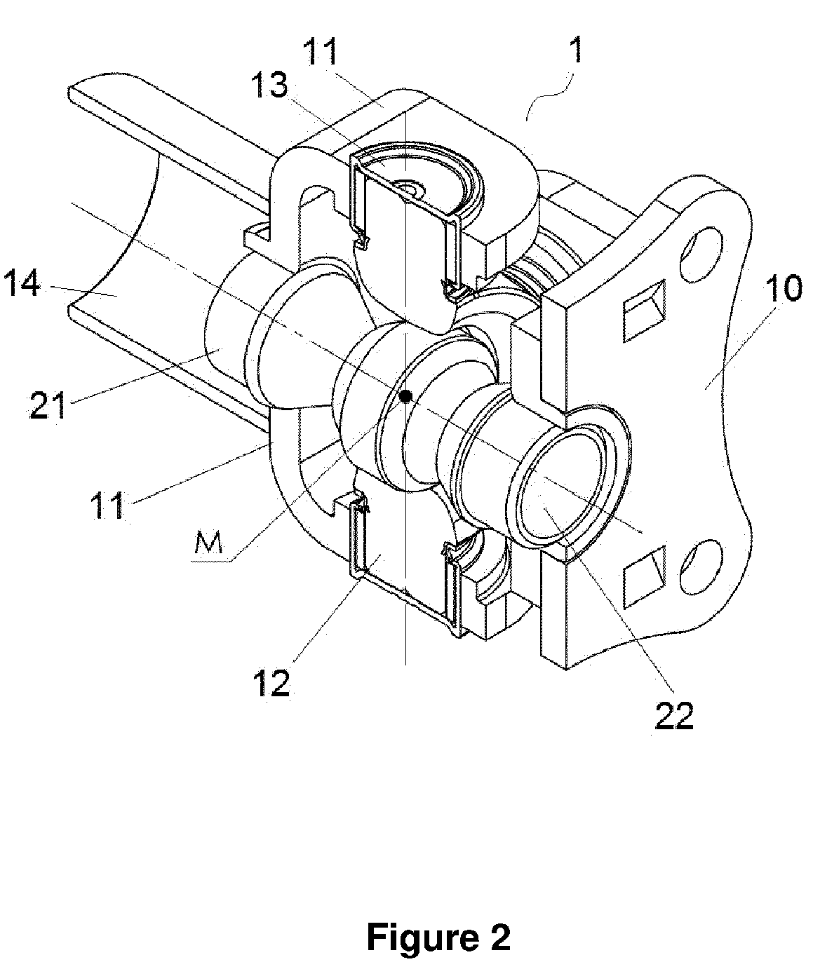
- FIG 2 a perspective, cross-sectional view of a preferred embodiment of the cardan joint (1) embodiment which is the subject of the invention has been given.
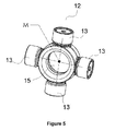
- the spider (12) which is one of the essential elements of the joint (1) has been designed, as it will also be seen from Figure 5 , in a way comprising circular spider spacing (15) in the central hub section thereof.
- a support member (20) Inside said spider hub spacing (15), a support member (20) has been positioned in a way coincident with spacing (15) centres (M).
- Spherical joint support member (20) being one of the essential elements of the invention is comprised of a spherical headed male piece (21) and a spherical bushing female piece (22).
- spherical headed male piece (21) While one side of spherical headed male piece (21) has a spherical (23) form, it has a hausing cylinder (25) on the other side contained thereto. While one side of the spherical bushing female piece (21) has a geometry comprising a spherical bushing (24) form in itself, it has a hausing cylinder (25) form similar to the spherical headed female piece (21) on the other side of itself contained. In Figure 7 , there is found a perspective view of spherical joint support member (20) in disassembled state.
- spherical headed male piece (21) and spherical bushing female piece (22) are in embedded state.
- the sphere (23) contained in geometry of spherical headed male piece (21) is located inside spherical bushing (24) of spherical bushing female piece (22) and homocentric (M) sphere and spherical bushing (23,24) are capable of moving by sliding over one another.
- the sphere (23) contained in geometry of spherical joint support member (20) and the centre (M) of spherical bushing (24) is at the same time the centre of axis of rotation of the shafts with which cardan joints (1) is in connection.
- This centre (M) indicated in Figure 2 is at the same time centre of bending of the system in which cardan joint (1) is contained.
- Spherical joint support member (20) has been embedded to circular bushing (17) located on flange yoke and tube yoke (10,11) generally connected with a shaft by means of hausing cyclinder (25) located on both ends thereof in a way being homocentric with the cardan joints (1).
- spherical joint support member (20) being homocentric with the shafts connected with the joint (1) is also found in angular position in the same way. Transition of the joint form straight position indicated in Figure 3 to angular position indicated in Figure 4 is achieved via spherical headed male piece (21) and spherical bushing female piece (22) constituting spherical joint support member's hanging positions by sliding one over another.
- spherical joint supported member (20) and cardan joint (1) work homocentric.
- spherical joint supported member (20) and cardan joint (1) work homocentric.
- cardan joint's support member working homocentric also inclines as much angle ( ⁇ ).
- the angle that cardan joint (1) forms with spider bearings (13) is similarly supported with spherical joint support member (20) as well.
- hausing cylinder (25) Over geometry of spherical joint support member (20), there is found hausing cylinder (25) each.
- the spherical joint support member (20) has been positioned, on one hand, to a bushing (17) located on flange yoke (10) by means of said hausing cylinder (25) and to a bushing (18) located on tube yoke (11) in a way being homocentric with said flange yoke and tube yoke (10,11).
- thrust (32) created on spider's bearings (13) by the spider (12) is supported by provision of homocentric rotation of flange yoke (10) and tube yoke (11) whose three dimensional views are contained in Figure 6 .
- a base washer (31) is placed into spider bearing (13) in embodiments used in the prior art, in order for it to meet the thrust (32).
- spherical joint support member (20) contained in invention's embodiment eliminates the need for a base washer by preventing formation of the thrusts (32) on spider bearing (13).
- spherical joint support member (20) positioned in the centre of the axis of rotation of cardan shafts with which cardan joint (1) in connection, centring of cardan shaft on axis of rotation and operation of the shaft under less vibration have been achieved.
- a cardan shaft capable of producing less vibration can work at higher speeds.
- the cardan joint (1) which is the subject of the invention, comprising a spherical joint support member (20) is also suitable for use on other machinery and systems where there are torque and rotation motion applications.
Landscapes
- Engineering & Computer Science (AREA)
- General Engineering & Computer Science (AREA)
- Mechanical Engineering (AREA)
- Support Of The Bearing (AREA)
- Pivots And Pivotal Connections (AREA)
Abstract

Description
- The invention relates to developments revealed in cardan joint used on motorised vehicles in many more fields of application, chiefly in sectors such as automotive, machinery production, can be available on both ends or in the centres of cardan shafts, doing the job of transmitting the rotation motion and torque produced by engine in a way that will allow formation of an angle of a certain degree between axes of rotation.
- The invention is particularly about a new cardan joint embodiment where loads on bearings acting on the spider and the arms thereof are decreased, life of the joint is elongated and spinning speeds of the cardan shaft are increased via resisting axial forces by means of a support member positioned in the centre of the spider.
- Cardan joints are special designs useful for achievement of angular motion between shafts that transmit torque and rotation motion. While cardan joints are used mainly in sectors such as automotive, machinery production, they have had a highly dense rate of usage in a great number of other fields for a long time as well. Due to their having a broad range of usage and history of their essential design dating back to very ancient times, many studies have been carried out on cardan joints, different assembly and production methods have been devised.
- Basic design of cardan joints comprise 2 yoke pieces comprising different types of connection and bodies, and special bearings with 4 arms in form of a "plus" known as spider located among such pieces and providing reciprocal motion of the arms thereof as well as embodiments formed via linking of them with both yoke pieces. There is a 90º angle on axis of rotation between the yoke pieces matched with reciprocal arms of the spider and the special type of bearings.
- In applications where cardan joint gets bended with excess angle, joint types known in the literature as double cardan joint are used instead of single cardan joint since the joint causes too much vibration and oscillation of angular velocity. In embodiment of most of these cardan shafts, there are provided spherical embodiments for centring purpose that allow inlet and outlet pieces to make an equal angle with the main body. As an example of these embodiments, there are patents such as
DE102005053362A1 ,FR2955161 A1 US2003228920A1 ,US2008280689A1 , and so on. The greatest difference of these embodiments from the embodiment of the invention is that it is bushing on the principle of linking up of two cardan joints. Spherical embodiment positioned in the centre provides linking up of sequentially positioned joints onto the main body each time with congruent angle. In the literature, these types of joints are termed "self-centring double cardan joints". Spherical member is not generally expected to carry loads or to block exit forces applied on spider joint bearings. A further difference is that the spherical member contained in double cardan joint embodiment is found between two spider joints. As one spider joint was used in invention's embodiment, wherein spherical joint being positioned to the centre of universal joint (M). - Spider piece, on which special type of bearing runs over its arms has the weakest geometry in cardan joint embodiment. Angular velocity and torque on cardan shaft are transmitted from one piece to the other cardan shaft via this piece. In addition to angular velocity and torque, in same cases axial forces along the cardan shaft are also transmitted over arms of spider to the other cardan shaft. Particularly on motorised vehicles where cardan shafts are employed, axial forces produced on cardan shaft with acting of suspension movement lead to put stress on spider's arms. Maximum torque value that can be carried by the spider, which is stipulated in computations that it will be exposed to only radial torque, becomes low since it is exposed to stress in axial direction together with radial torques in the direction of rotation under running conditions. In order for spider to also meet axial loads, it requires being designed according to much higher values than what is stipulated.
- Spider bearings, produced in special type, acting on spider's arms are exposed to irregular additional loads due to stresss produced in axial direction and over time abrasions and deformations occur in the areas where bearing rollers work. These abrasions and deformations occurring reduce working life of cardan joint significantly.
- In
Figure 8 , a three dimensional, cross-sectional view of a cardan shaft according to prior art is given. In this embodiment, thrust (32) is caused by spider on spider bearings in cases where embodiments acts angularly. In order for it to resist the thrust (32) occurring, base washer (312) is placed inside spider bearing (13) in existing embodiments. - The present invention relates to a new embodiment meeting above disclosed requirements, eliminating all of the disadvantages, bringing some additional advantages and formed through addition of a spherical joint to the centre of cardan joint.
- A purpose of the invention is designation of the central area of the spider piece constituting the main component of cardan joint as empty and to reveal a new cardan joint embodiment where spherical joint connected to cardan shafts from front or rear or to the yoke pieces constituting connection flanges, is positioned within this spacing created.
- Exposure of bearings acting on spider and arms thereof to radial loads only in the direction of rotation torque has been targeted by supporting axial forces that will fall upon the embodiment, by means of spherical - joint support member positioned as overlapping with centre of cardan joint bending center.
- Another purpose of the invention is both to increase total torque that joint can bear and to achieve elongation of working life of the joint through prevention of deformation by wearing out less, by means of providing more comfortable operation of spider bearings.
- A further purpose of the invention, on the other hand, is to achieve centring of cardan shaft on the axis of rotation and operation of cardan shaft under less vibration by means of spherical joint positioned in the centre of axis of rotation on both ends of cardan shaft. A cardan shaft that produces less vibration can work at higher speeds.
- With this invention, it is also targeted to prevent of thrust created by spider on spider bearings by achieving homocentric rotation of inlet and outlet connection members.
- A further purpose of the invention is elimination of the need felt for utilisation of base washer inside spider bearing.
- By means of the jointed support member developed with the invention, it is targeted to prevent of thrust of the spider on spider bearings by achieving homocentric rotation of yoke flange and of tube yoke.
- The structural and characteristic properties and all of its advantages of the invention will be understood more clearly from the drawings provided below and from the detailed description written by making references to these drawings and therefore the assessment should be made by taking these drawings and the detailed description into account.
- To understand the embodiment and the advantages of the present invention with the additional elements in the best way, it should be evaluated together with the figures whose descriptions are made below.
-
Figure 1 is a perspective view of central unit supported cardan joint which is the subject of the invention. -
Figure 2 is a three dimensional view of a cross-section of central unit supported cardan joint which is the subject of the invention. -
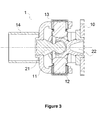
Figure 3 is a cross-sectional view of central unit supported cardan joint which is the subject of the invention in straight position. -
Figure 4 is a cross-sectional view of central unit supported cardan joint which is the subject of the invention from side profile, in angular position. -
Figure 5 is a three dimensional view of spider embodiment comprising a spacing in the centre part thereof. -
Figure 6 is three dimensional views of flange yoke and tube yoke. -
Figure 7 is a three dimensional view spherical joint support member in disassembled form. -
Figure 8 is a three dimensional, cross-sectional view of cardan joint of the prior art. - The drawings need not absolutely be put to scale the details not necessary to understand the invention may have been omitted. Furthermore, the elements that are at least substantially identical, or at least have substantially identical functions are indicated with the same number.
-
1. Cardan Joint 10. Flange Yoke 11. Tube Yoke 12. Spider 13. Spider Bearing 14. Cardan Shaft Tube 15. Spider Hub Spacing 16. Roller Bearing Bushing 17. Support Member Bushing (Flange Yoke) 18. Support Member Bushing (Tube Yoke) 20. Spherical Joint Support Member 21. Spherical Headed Male Piece 22. Spherical Bushing Female Piece 23. Sphere 24. Spherical Bushing 25. Hausing cylinder 31. Base Washer 32. Thrust M. Piece Centre - In this detailed description, preferred embodiments of the cardan joint (1) comprising a spherical joint support member (20), which is the subject of the invention, are described only for a better understanding of the subject-matter and in a way not constituting any limiting effect.
- The invention relates to developments revealed in cardan joint used on motorised vehicles in many more fields of application, chiefly in sectors such as automotive, machinery production, can be available on both ends or in the centres of cardan shafts, doing the job of transmitting the rotation motion and torque produced by engine in a way that will allow formation of an angle of a certain degree between axes of rotation. In
Figure 1 , a three dimensional view of the cardan joint (1) which is the subject of the invention is given. - Specialty of the invention is that it is a cardan joint (1) embodiment where loads on bearings (13) acting on the spider (12) and the arms thereof are decreased, life of the joint (1) is elongated and spinning speeds of the cardan shaft are increased via meeting axial forces by means of a spherical joint support member (20) positioned in the centre of the spider (12).
- As will be seen from its cross-section is
Figure 3 , the cardan joint (1) which is the subject of the invention is comprised of a spider (12) having arms in form of a plus in the centre and flange yoke and tube yoke (10,11) in different geometry linked with spider bearings (13) located on reciprocal arms of said spider (12). Spider bearings (13) make a spinning motion inside the roller bearing bushings (16) located on flange yoke and tube yoke (10,11). As the flange yoke (10) member and the cardan joint (1) can be connected to another connection piece by use of various fixing members, they can also be welded onto cardan shaft tube (14) of cardan joint (1) by use of tube yoke (11) member. - While flange yoke (10) as well as transmission box of cardan shaft used on vehicles can be connected to pieces such as differential flange, intermediate bearing flange via connecting members bolts and nuts, they can be welded to cardan shaft tube (14) with tube yoke (11).
- In
Figure 2 , a perspective, cross-sectional view of a preferred embodiment of the cardan joint (1) embodiment which is the subject of the invention has been given. In this embodiment, the spider (12) which is one of the essential elements of the joint (1) has been designed, as it will also be seen fromFigure 5 , in a way comprising circular spider spacing (15) in the central hub section thereof. Inside said spider hub spacing (15), a support member (20) has been positioned in a way coincident with spacing (15) centres (M). Spherical joint support member (20) being one of the essential elements of the invention is comprised of a spherical headed male piece (21) and a spherical bushing female piece (22). While one side of spherical headed male piece (21) has a spherical (23) form, it has a hausing cylinder (25) on the other side contained thereto. While one side of the spherical bushing female piece (21) has a geometry comprising a spherical bushing (24) form in itself, it has a hausing cylinder (25) form similar to the spherical headed female piece (21) on the other side of itself contained. InFigure 7 , there is found a perspective view of spherical joint support member (20) in disassembled state. - In practice, spherical headed male piece (21) and spherical bushing female piece (22) are in embedded state. The sphere (23) contained in geometry of spherical headed male piece (21) is located inside spherical bushing (24) of spherical bushing female piece (22) and homocentric (M) sphere and spherical bushing (23,24) are capable of moving by sliding over one another. The sphere (23) contained in geometry of spherical joint support member (20) and the centre (M) of spherical bushing (24) is at the same time the centre of axis of rotation of the shafts with which cardan joints (1) is in connection. This centre (M) indicated in
Figure 2 is at the same time centre of bending of the system in which cardan joint (1) is contained. - Spherical joint support member (20) has been embedded to circular bushing (17) located on flange yoke and tube yoke (10,11) generally connected with a shaft by means of hausing cyclinder (25) located on both ends thereof in a way being homocentric with the cardan joints (1).
- As shown in a cross-sectional, side profile view of a preferred embodiment of cardan joint (1) in
Figure (1 ), in cases where it is positioned angularly, spherical joint support member (20) being homocentric with the shafts connected with the joint (1) is also found in angular position in the same way. Transition of the joint form straight position indicated inFigure 3 to angular position indicated inFigure 4 is achieved via spherical headed male piece (21) and spherical bushing female piece (22) constituting spherical joint support member's hanging positions by sliding one over another. In traditional cardan joint embodiment, axial forces transferred from one flange yoke (10) to another tube yoke (11) over spider's arms are transferred to another piece over spherical joint support member (20) in invention's embodiment. Thus, load and service life that can be carried by spider (12) which is exposed only to torque loads in the direction of rotation are increased. - As will be understood from the perspective views of cardan joint (1), which is the subject of the invention, in straight positioned state in
Figure 3 , and angularly positioned state inFigure 4 , spherical joint supported member (20) and cardan joint (1) work homocentric. For example; if cardan joint inclines as much angle (α) inFigure 1 , cardan joint's support member working homocentric also inclines as much angle (α). The angle that cardan joint (1) forms with spider bearings (13) is similarly supported with spherical joint support member (20) as well. - Over geometry of spherical joint support member (20), there is found hausing cylinder (25) each. The spherical joint support member (20) has been positioned, on one hand, to a bushing (17) located on flange yoke (10) by means of said hausing cylinder (25) and to a bushing (18) located on tube yoke (11) in a way being homocentric with said flange yoke and tube yoke (10,11). Thus, thrust (32) created on spider's bearings (13) by the spider (12) is supported by provision of homocentric rotation of flange yoke (10) and tube yoke (11) whose three dimensional views are contained in
Figure 6 . A base washer (31) is placed into spider bearing (13) in embodiments used in the prior art, in order for it to meet the thrust (32). As described above, spherical joint support member (20) contained in invention's embodiment eliminates the need for a base washer by preventing formation of the thrusts (32) on spider bearing (13). - By means of spherical joint support member (20) positioned in the centre of the axis of rotation of cardan shafts with which cardan joint (1) in connection, centring of cardan shaft on axis of rotation and operation of the shaft under less vibration have been achieved. A cardan shaft capable of producing less vibration can work at higher speeds.
- By means of spherical joint support member (20) of cardan joint (1) positioned coincidently with centre of bending, exposure of bearings (13) acting on spider (12) and arms thereof to radial loads only in the direction of rotation torque has been achieved by meeting axial forces arising during operation of the system. As more comfortable operation of bearings (13) increases total torque that can be carried by joint, it also elongates working life of the joint by preventing deformation by wearing out less.
- In addition to being usable on cardan shafts, the cardan joint (1), which is the subject of the invention, comprising a spherical joint support member (20) is also suitable for use on other machinery and systems where there are torque and rotation motion applications.
Claims (5)
- A cardan joint (1) embodiment located on cardan shafts transmitting rotation motion and torque on motorised vehicles, and it is characterised in that; it comprises a spherical joint support member (20) that is coincident with cardan joint (1) and its centre (M) and comprised of a sphere (23) and a spherical bushing female piece (22) having bushing geometry suitable for said sphere (23) and capable of sliding one over another.
- A cardan joint (1) according to Claim 1, and it is characterised in that; spherical joint support member (20) is homocentrical (M) connected to yoke pieces (10,11) located at the inlet and outlet of the joint (1).
- A cardan joint (1) according to Claim 1 to 2, and it is characterised in that; centre (M) of bending of cardan joint (1) and centre (M) of spherical joint support member (20) are coincident.
- A cardan joint (1) according to Claim 1 to 2, and it is characterised in that; it blocks the thrust (32) created on spider bearings (13) by the spider (12) by means of rotation of flange yoke (10) and of tube yoke (11) homocentrical.
- A cardan joint (1) according to Claim 1 to 4, and it is characterised in that; cardan joint (1) providing exposure of bearings (13) running on spider (12) and arms thereof to radial loads only in the direction of rotation torque by meeting axial forces that will fall upon the system comprises spherical joint support member (20) positioned coincidently with the centre of bending.
Priority Applications (3)
| Application Number | Priority Date | Filing Date | Title |
|---|---|---|---|
| PL13168112T PL2803877T3 (en) | 2013-05-16 | 2013-05-16 | Cardan joint supported with central unit |
| ES13168112.4T ES2692968T3 (en) | 2013-05-16 | 2013-05-16 | Cardan joint supported with central unit |
| EP13168112.4A EP2803877B1 (en) | 2013-05-16 | 2013-05-16 | Cardan joint supported with central unit |
Applications Claiming Priority (1)
| Application Number | Priority Date | Filing Date | Title |
|---|---|---|---|
| EP13168112.4A EP2803877B1 (en) | 2013-05-16 | 2013-05-16 | Cardan joint supported with central unit |
Publications (2)
| Publication Number | Publication Date |
|---|---|
| EP2803877A1 true EP2803877A1 (en) | 2014-11-19 |
| EP2803877B1 EP2803877B1 (en) | 2018-09-12 |
Family
ID=48470759
Family Applications (1)
| Application Number | Title | Priority Date | Filing Date |
|---|---|---|---|
| EP13168112.4A Active EP2803877B1 (en) | 2013-05-16 | 2013-05-16 | Cardan joint supported with central unit |
Country Status (3)
| Country | Link |
|---|---|
| EP (1) | EP2803877B1 (en) |
| ES (1) | ES2692968T3 (en) |
| PL (1) | PL2803877T3 (en) |
Cited By (1)
| Publication number | Priority date | Publication date | Assignee | Title |
|---|---|---|---|---|
| US10968959B2 (en) | 2018-06-06 | 2021-04-06 | Spidertrax Inc. | Universal joint with reinforced yoke ears and positively locked trunnions |
Citations (8)
| Publication number | Priority date | Publication date | Assignee | Title |
|---|---|---|---|---|
| DE826222C (en) * | 1950-11-01 | 1952-11-17 | Ludwig Baersch Dipl Ing | Joint to connect two shafts |
| US2984997A (en) * | 1960-06-06 | 1961-05-23 | Gen Motors Corp | Universal joint |
| FR2244377A5 (en) * | 1973-09-19 | 1975-04-11 | Bastid Philippe | Constant speed universal shaft joint - shaft ends have projecting pivot arms joined by a ball and socket joint |
| FR2611017A1 (en) * | 1987-02-12 | 1988-08-19 | Linde Ag | Double universal drive joint |
| US20030228920A1 (en) | 1998-01-19 | 2003-12-11 | Krupp Presta Ag | Double joint for steering axles in automobiles |
| DE102005053362A1 (en) | 2005-11-07 | 2007-05-16 | Spicer Gelenkwellenbau Gmbh | Centering arrangement at double cardan joint, comprising first articulated fork, which has two first supports, which are connected through first bridge that supports bearing pin centered on first longitudinal axis |
| US20080280689A1 (en) | 2007-05-07 | 2008-11-13 | Philip Mazziotti | Double cardan joint |
| FR2955161A1 (en) | 2010-05-12 | 2011-07-15 | Beguin Patrick Marcouf Hubert | Universal spherical cardan joint for transmitting torque between axles, has male element with grooves sectioning trapeze, and set of needle/roller type rolling elements arranged on cylindrical bottom face of lower part of junction element |
-
2013
- 2013-05-16 EP EP13168112.4A patent/EP2803877B1/en active Active
- 2013-05-16 ES ES13168112.4T patent/ES2692968T3/en active Active
- 2013-05-16 PL PL13168112T patent/PL2803877T3/en unknown
Patent Citations (8)
| Publication number | Priority date | Publication date | Assignee | Title |
|---|---|---|---|---|
| DE826222C (en) * | 1950-11-01 | 1952-11-17 | Ludwig Baersch Dipl Ing | Joint to connect two shafts |
| US2984997A (en) * | 1960-06-06 | 1961-05-23 | Gen Motors Corp | Universal joint |
| FR2244377A5 (en) * | 1973-09-19 | 1975-04-11 | Bastid Philippe | Constant speed universal shaft joint - shaft ends have projecting pivot arms joined by a ball and socket joint |
| FR2611017A1 (en) * | 1987-02-12 | 1988-08-19 | Linde Ag | Double universal drive joint |
| US20030228920A1 (en) | 1998-01-19 | 2003-12-11 | Krupp Presta Ag | Double joint for steering axles in automobiles |
| DE102005053362A1 (en) | 2005-11-07 | 2007-05-16 | Spicer Gelenkwellenbau Gmbh | Centering arrangement at double cardan joint, comprising first articulated fork, which has two first supports, which are connected through first bridge that supports bearing pin centered on first longitudinal axis |
| US20080280689A1 (en) | 2007-05-07 | 2008-11-13 | Philip Mazziotti | Double cardan joint |
| FR2955161A1 (en) | 2010-05-12 | 2011-07-15 | Beguin Patrick Marcouf Hubert | Universal spherical cardan joint for transmitting torque between axles, has male element with grooves sectioning trapeze, and set of needle/roller type rolling elements arranged on cylindrical bottom face of lower part of junction element |
Cited By (2)
| Publication number | Priority date | Publication date | Assignee | Title |
|---|---|---|---|---|
| US10968959B2 (en) | 2018-06-06 | 2021-04-06 | Spidertrax Inc. | Universal joint with reinforced yoke ears and positively locked trunnions |
| US11754125B2 (en) | 2018-06-06 | 2023-09-12 | Spidertrax, Inc. | Universal joint with reinforced yoke ears |
Also Published As
| Publication number | Publication date |
|---|---|
| PL2803877T3 (en) | 2019-02-28 |
| ES2692968T3 (en) | 2018-12-05 |
| EP2803877B1 (en) | 2018-09-12 |
Similar Documents
| Publication | Publication Date | Title |
|---|---|---|
| EP3156678B1 (en) | Articulating torsional coupling | |
| US3638454A (en) | Flexible coupling | |
| EP3168490A1 (en) | Tripod-type constant-velocity universal joint | |
| GB2522767A (en) | Coupling | |
| KR20230107546A (en) | gear pair and gear reducer | |
| CN111520416B (en) | Sliding pair structure of steering intermediate shaft of automobile | |
| EP2803877B1 (en) | Cardan joint supported with central unit | |
| IT8448253A1 (en) | COUPLING DEVICE FOR MECHANICAL DRIVE, ESPECIALLY AT CONSTANT SPEED | |
| CN201739370U (en) | Integral type shaft head and ball cage coupler with mandril | |
| US9206856B2 (en) | Coupling | |
| CN110641566A (en) | Tracked vehicle suspension assembly and tracked vehicle | |
| US20150292565A1 (en) | Lightweight joint for transmitting rotational movements | |
| CN104315088A (en) | Novel cycloid needle roller damping speed reducer | |
| CN101672331A (en) | Structure of constant velocity universal joint | |
| CN204628269U (en) | A kind of straight-tooth end-tooth pivoting support | |
| CA2435398C (en) | Coupling | |
| CN203778493U (en) | Cross shaft assembly of universal coupling | |
| US20080034904A1 (en) | Drive Gear Assembly | |
| CN204184431U (en) | A kind of steering intermediate shaft assembly and automobile | |
| CN201739371U (en) | Solid-shaft head ball cage coupling device | |
| CN222687152U (en) | Lightweight agricultural machinery transmission shaft | |
| RU2590428C2 (en) | Ball hinge | |
| CN211175092U (en) | A double-shaft sliding adjustment conjoined ball cage universal joint coupling | |
| Sanghani et al. | Optimization and finite element analysis of single joint universal coupling in automobile truck | |
| CN110399659B (en) | Length design method of switching spline shaft |
Legal Events
| Date | Code | Title | Description |
|---|---|---|---|
| PUAI | Public reference made under article 153(3) epc to a published international application that has entered the european phase |
Free format text: ORIGINAL CODE: 0009012 |
|
| 17P | Request for examination filed |
Effective date: 20130516 |
|
| AK | Designated contracting states |
Kind code of ref document: A1 Designated state(s): AL AT BE BG CH CY CZ DE DK EE ES FI FR GB GR HR HU IE IS IT LI LT LU LV MC MK MT NL NO PL PT RO RS SE SI SK SM TR |
|
| AX | Request for extension of the european patent |
Extension state: BA ME |
|
| R17P | Request for examination filed (corrected) |
Effective date: 20150401 |
|
| RAP1 | Party data changed (applicant data changed or rights of an application transferred) |
Owner name: TIRSAN KARDAN SANAYI VE TICARET ANONIM SIRKETI |
|
| 17Q | First examination report despatched |
Effective date: 20160810 |
|
| STAA | Information on the status of an ep patent application or granted ep patent |
Free format text: STATUS: EXAMINATION IS IN PROGRESS |
|
| GRAP | Despatch of communication of intention to grant a patent |
Free format text: ORIGINAL CODE: EPIDOSNIGR1 |
|
| STAA | Information on the status of an ep patent application or granted ep patent |
Free format text: STATUS: GRANT OF PATENT IS INTENDED |
|
| INTG | Intention to grant announced |
Effective date: 20180619 |
|
| GRAS | Grant fee paid |
Free format text: ORIGINAL CODE: EPIDOSNIGR3 |
|
| GRAA | (expected) grant |
Free format text: ORIGINAL CODE: 0009210 |
|
| STAA | Information on the status of an ep patent application or granted ep patent |
Free format text: STATUS: THE PATENT HAS BEEN GRANTED |
|
| AK | Designated contracting states |
Kind code of ref document: B1 Designated state(s): AL AT BE BG CH CY CZ DE DK EE ES FI FR GB GR HR HU IE IS IT LI LT LU LV MC MK MT NL NO PL PT RO RS SE SI SK SM TR |
|
| REG | Reference to a national code |
Ref country code: GB Ref legal event code: FG4D |
|
| REG | Reference to a national code |
Ref country code: CH Ref legal event code: EP |
|
| REG | Reference to a national code |
Ref country code: IE Ref legal event code: FG4D |
|
| REG | Reference to a national code |
Ref country code: DE Ref legal event code: R096 Ref document number: 602013043447 Country of ref document: DE |
|
| REG | Reference to a national code |
Ref country code: AT Ref legal event code: REF Ref document number: 1040961 Country of ref document: AT Kind code of ref document: T Effective date: 20181015 |
|
| REG | Reference to a national code |
Ref country code: SE Ref legal event code: TRGR |
|
| REG | Reference to a national code |
Ref country code: NL Ref legal event code: FP |
|
| REG | Reference to a national code |
Ref country code: ES Ref legal event code: FG2A Ref document number: 2692968 Country of ref document: ES Kind code of ref document: T3 Effective date: 20181205 |
|
| REG | Reference to a national code |
Ref country code: LT Ref legal event code: MG4D |
|
| PG25 | Lapsed in a contracting state [announced via postgrant information from national office to epo] |
Ref country code: GR Free format text: LAPSE BECAUSE OF FAILURE TO SUBMIT A TRANSLATION OF THE DESCRIPTION OR TO PAY THE FEE WITHIN THE PRESCRIBED TIME-LIMIT Effective date: 20181213 Ref country code: NO Free format text: LAPSE BECAUSE OF FAILURE TO SUBMIT A TRANSLATION OF THE DESCRIPTION OR TO PAY THE FEE WITHIN THE PRESCRIBED TIME-LIMIT Effective date: 20181212 Ref country code: RS Free format text: LAPSE BECAUSE OF FAILURE TO SUBMIT A TRANSLATION OF THE DESCRIPTION OR TO PAY THE FEE WITHIN THE PRESCRIBED TIME-LIMIT Effective date: 20180912 Ref country code: LT Free format text: LAPSE BECAUSE OF FAILURE TO SUBMIT A TRANSLATION OF THE DESCRIPTION OR TO PAY THE FEE WITHIN THE PRESCRIBED TIME-LIMIT Effective date: 20180912 Ref country code: BG Free format text: LAPSE BECAUSE OF FAILURE TO SUBMIT A TRANSLATION OF THE DESCRIPTION OR TO PAY THE FEE WITHIN THE PRESCRIBED TIME-LIMIT Effective date: 20181212 Ref country code: FI Free format text: LAPSE BECAUSE OF FAILURE TO SUBMIT A TRANSLATION OF THE DESCRIPTION OR TO PAY THE FEE WITHIN THE PRESCRIBED TIME-LIMIT Effective date: 20180912 |
|
| PG25 | Lapsed in a contracting state [announced via postgrant information from national office to epo] |
Ref country code: AL Free format text: LAPSE BECAUSE OF FAILURE TO SUBMIT A TRANSLATION OF THE DESCRIPTION OR TO PAY THE FEE WITHIN THE PRESCRIBED TIME-LIMIT Effective date: 20180912 Ref country code: LV Free format text: LAPSE BECAUSE OF FAILURE TO SUBMIT A TRANSLATION OF THE DESCRIPTION OR TO PAY THE FEE WITHIN THE PRESCRIBED TIME-LIMIT Effective date: 20180912 Ref country code: HR Free format text: LAPSE BECAUSE OF FAILURE TO SUBMIT A TRANSLATION OF THE DESCRIPTION OR TO PAY THE FEE WITHIN THE PRESCRIBED TIME-LIMIT Effective date: 20180912 |
|
| PG25 | Lapsed in a contracting state [announced via postgrant information from national office to epo] |
Ref country code: EE Free format text: LAPSE BECAUSE OF FAILURE TO SUBMIT A TRANSLATION OF THE DESCRIPTION OR TO PAY THE FEE WITHIN THE PRESCRIBED TIME-LIMIT Effective date: 20180912 Ref country code: IS Free format text: LAPSE BECAUSE OF FAILURE TO SUBMIT A TRANSLATION OF THE DESCRIPTION OR TO PAY THE FEE WITHIN THE PRESCRIBED TIME-LIMIT Effective date: 20190112 Ref country code: RO Free format text: LAPSE BECAUSE OF FAILURE TO SUBMIT A TRANSLATION OF THE DESCRIPTION OR TO PAY THE FEE WITHIN THE PRESCRIBED TIME-LIMIT Effective date: 20180912 Ref country code: CZ Free format text: LAPSE BECAUSE OF FAILURE TO SUBMIT A TRANSLATION OF THE DESCRIPTION OR TO PAY THE FEE WITHIN THE PRESCRIBED TIME-LIMIT Effective date: 20180912 |
|
| PG25 | Lapsed in a contracting state [announced via postgrant information from national office to epo] |
Ref country code: SM Free format text: LAPSE BECAUSE OF FAILURE TO SUBMIT A TRANSLATION OF THE DESCRIPTION OR TO PAY THE FEE WITHIN THE PRESCRIBED TIME-LIMIT Effective date: 20180912 Ref country code: PT Free format text: LAPSE BECAUSE OF FAILURE TO SUBMIT A TRANSLATION OF THE DESCRIPTION OR TO PAY THE FEE WITHIN THE PRESCRIBED TIME-LIMIT Effective date: 20190112 Ref country code: SK Free format text: LAPSE BECAUSE OF FAILURE TO SUBMIT A TRANSLATION OF THE DESCRIPTION OR TO PAY THE FEE WITHIN THE PRESCRIBED TIME-LIMIT Effective date: 20180912 |
|
| REG | Reference to a national code |
Ref country code: DE Ref legal event code: R097 Ref document number: 602013043447 Country of ref document: DE |
|
| PLBE | No opposition filed within time limit |
Free format text: ORIGINAL CODE: 0009261 |
|
| STAA | Information on the status of an ep patent application or granted ep patent |
Free format text: STATUS: NO OPPOSITION FILED WITHIN TIME LIMIT |
|
| PG25 | Lapsed in a contracting state [announced via postgrant information from national office to epo] |
Ref country code: DK Free format text: LAPSE BECAUSE OF FAILURE TO SUBMIT A TRANSLATION OF THE DESCRIPTION OR TO PAY THE FEE WITHIN THE PRESCRIBED TIME-LIMIT Effective date: 20180912 |
|
| 26N | No opposition filed |
Effective date: 20190613 |
|
| PG25 | Lapsed in a contracting state [announced via postgrant information from national office to epo] |
Ref country code: SI Free format text: LAPSE BECAUSE OF FAILURE TO SUBMIT A TRANSLATION OF THE DESCRIPTION OR TO PAY THE FEE WITHIN THE PRESCRIBED TIME-LIMIT Effective date: 20180912 |
|
| REG | Reference to a national code |
Ref country code: CH Ref legal event code: PL |
|
| PG25 | Lapsed in a contracting state [announced via postgrant information from national office to epo] |
Ref country code: LI Free format text: LAPSE BECAUSE OF NON-PAYMENT OF DUE FEES Effective date: 20190531 Ref country code: MC Free format text: LAPSE BECAUSE OF FAILURE TO SUBMIT A TRANSLATION OF THE DESCRIPTION OR TO PAY THE FEE WITHIN THE PRESCRIBED TIME-LIMIT Effective date: 20180912 Ref country code: CH Free format text: LAPSE BECAUSE OF NON-PAYMENT OF DUE FEES Effective date: 20190531 |
|
| REG | Reference to a national code |
Ref country code: BE Ref legal event code: MM Effective date: 20190531 |
|
| PG25 | Lapsed in a contracting state [announced via postgrant information from national office to epo] |
Ref country code: LU Free format text: LAPSE BECAUSE OF NON-PAYMENT OF DUE FEES Effective date: 20190516 |
|
| PG25 | Lapsed in a contracting state [announced via postgrant information from national office to epo] |
Ref country code: TR Free format text: LAPSE BECAUSE OF FAILURE TO SUBMIT A TRANSLATION OF THE DESCRIPTION OR TO PAY THE FEE WITHIN THE PRESCRIBED TIME-LIMIT Effective date: 20180912 |
|
| PG25 | Lapsed in a contracting state [announced via postgrant information from national office to epo] |
Ref country code: IE Free format text: LAPSE BECAUSE OF NON-PAYMENT OF DUE FEES Effective date: 20190516 |
|
| PG25 | Lapsed in a contracting state [announced via postgrant information from national office to epo] |
Ref country code: BE Free format text: LAPSE BECAUSE OF NON-PAYMENT OF DUE FEES Effective date: 20190531 |
|
| REG | Reference to a national code |
Ref country code: AT Ref legal event code: UEP Ref document number: 1040961 Country of ref document: AT Kind code of ref document: T Effective date: 20180912 |
|
| PG25 | Lapsed in a contracting state [announced via postgrant information from national office to epo] |
Ref country code: CY Free format text: LAPSE BECAUSE OF FAILURE TO SUBMIT A TRANSLATION OF THE DESCRIPTION OR TO PAY THE FEE WITHIN THE PRESCRIBED TIME-LIMIT Effective date: 20180912 |
|
| PG25 | Lapsed in a contracting state [announced via postgrant information from national office to epo] |
Ref country code: MT Free format text: LAPSE BECAUSE OF FAILURE TO SUBMIT A TRANSLATION OF THE DESCRIPTION OR TO PAY THE FEE WITHIN THE PRESCRIBED TIME-LIMIT Effective date: 20180912 Ref country code: HU Free format text: LAPSE BECAUSE OF FAILURE TO SUBMIT A TRANSLATION OF THE DESCRIPTION OR TO PAY THE FEE WITHIN THE PRESCRIBED TIME-LIMIT; INVALID AB INITIO Effective date: 20130516 |
|
| PG25 | Lapsed in a contracting state [announced via postgrant information from national office to epo] |
Ref country code: MK Free format text: LAPSE BECAUSE OF FAILURE TO SUBMIT A TRANSLATION OF THE DESCRIPTION OR TO PAY THE FEE WITHIN THE PRESCRIBED TIME-LIMIT Effective date: 20180912 |
|
| PGFP | Annual fee paid to national office [announced via postgrant information from national office to epo] |
Ref country code: PL Payment date: 20250227 Year of fee payment: 13 |
|
| PGFP | Annual fee paid to national office [announced via postgrant information from national office to epo] |
Ref country code: NL Payment date: 20250513 Year of fee payment: 13 |
|
| PGFP | Annual fee paid to national office [announced via postgrant information from national office to epo] |
Ref country code: DE Payment date: 20250521 Year of fee payment: 13 |
|
| PGFP | Annual fee paid to national office [announced via postgrant information from national office to epo] |
Ref country code: GB Payment date: 20250504 Year of fee payment: 13 Ref country code: ES Payment date: 20250605 Year of fee payment: 13 |
|
| PGFP | Annual fee paid to national office [announced via postgrant information from national office to epo] |
Ref country code: IT Payment date: 20250522 Year of fee payment: 13 |
|
| PGFP | Annual fee paid to national office [announced via postgrant information from national office to epo] |
Ref country code: FR Payment date: 20250515 Year of fee payment: 13 |
|
| PGFP | Annual fee paid to national office [announced via postgrant information from national office to epo] |
Ref country code: AT Payment date: 20250521 Year of fee payment: 13 |
|
| PGFP | Annual fee paid to national office [announced via postgrant information from national office to epo] |
Ref country code: SE Payment date: 20250518 Year of fee payment: 13 |