EP2803633A1 - Dispositif doté d'un élément optique suspendu pivotant - Google Patents
Dispositif doté d'un élément optique suspendu pivotant Download PDFInfo
- Publication number
- EP2803633A1 EP2803633A1 EP14168396.1A EP14168396A EP2803633A1 EP 2803633 A1 EP2803633 A1 EP 2803633A1 EP 14168396 A EP14168396 A EP 14168396A EP 2803633 A1 EP2803633 A1 EP 2803633A1
- Authority
- EP
- European Patent Office
- Prior art keywords
- actuators
- curved
- optical element
- histogram
- micromirror
- Prior art date
- Legal status (The legal status is an assumption and is not a legal conclusion. Google has not performed a legal analysis and makes no representation as to the accuracy of the status listed.)
- Granted
Links
- 230000003287 optical effect Effects 0.000 title claims abstract description 21
- 230000008859 change Effects 0.000 claims description 4
- 239000000463 material Substances 0.000 description 13
- 239000000758 substrate Substances 0.000 description 11
- 230000033001 locomotion Effects 0.000 description 5
- 230000007704 transition Effects 0.000 description 5
- 238000005452 bending Methods 0.000 description 4
- 230000015572 biosynthetic process Effects 0.000 description 4
- 239000010410 layer Substances 0.000 description 3
- 230000003071 parasitic effect Effects 0.000 description 3
- 230000007547 defect Effects 0.000 description 2
- 238000009826 distribution Methods 0.000 description 2
- 238000005530 etching Methods 0.000 description 2
- 239000002346 layers by function Substances 0.000 description 2
- 238000004519 manufacturing process Methods 0.000 description 2
- 238000000034 method Methods 0.000 description 2
- 230000010355 oscillation Effects 0.000 description 2
- 230000008569 process Effects 0.000 description 2
- 238000009827 uniform distribution Methods 0.000 description 2
- 238000010521 absorption reaction Methods 0.000 description 1
- 230000009471 action Effects 0.000 description 1
- 230000004913 activation Effects 0.000 description 1
- 230000001419 dependent effect Effects 0.000 description 1
- 238000006073 displacement reaction Methods 0.000 description 1
- 230000000694 effects Effects 0.000 description 1
- 230000005284 excitation Effects 0.000 description 1
- 239000012530 fluid Substances 0.000 description 1
- 238000009434 installation Methods 0.000 description 1
- 230000006641 stabilisation Effects 0.000 description 1
- 238000011105 stabilization Methods 0.000 description 1
Images


Classifications
-
- G—PHYSICS
- G02—OPTICS
- G02B—OPTICAL ELEMENTS, SYSTEMS OR APPARATUS
- G02B26/00—Optical devices or arrangements for the control of light using movable or deformable optical elements
- G02B26/08—Optical devices or arrangements for the control of light using movable or deformable optical elements for controlling the direction of light
- G02B26/0816—Optical devices or arrangements for the control of light using movable or deformable optical elements for controlling the direction of light by means of one or more reflecting elements
- G02B26/0833—Optical devices or arrangements for the control of light using movable or deformable optical elements for controlling the direction of light by means of one or more reflecting elements the reflecting element being a micromechanical device, e.g. a MEMS mirror, DMD
-
- B—PERFORMING OPERATIONS; TRANSPORTING
- B81—MICROSTRUCTURAL TECHNOLOGY
- B81B—MICROSTRUCTURAL DEVICES OR SYSTEMS, e.g. MICROMECHANICAL DEVICES
- B81B3/00—Devices comprising flexible or deformable elements, e.g. comprising elastic tongues or membranes
- B81B3/0035—Constitution or structural means for controlling the movement of the flexible or deformable elements
- B81B3/004—Angular deflection
- B81B3/0045—Improve properties related to angular swinging, e.g. control resonance frequency
-
- B—PERFORMING OPERATIONS; TRANSPORTING
- B81—MICROSTRUCTURAL TECHNOLOGY
- B81B—MICROSTRUCTURAL DEVICES OR SYSTEMS, e.g. MICROMECHANICAL DEVICES
- B81B2201/00—Specific applications of microelectromechanical systems
- B81B2201/04—Optical MEMS
- B81B2201/042—Micromirrors, not used as optical switches
-
- B—PERFORMING OPERATIONS; TRANSPORTING
- B81—MICROSTRUCTURAL TECHNOLOGY
- B81B—MICROSTRUCTURAL DEVICES OR SYSTEMS, e.g. MICROMECHANICAL DEVICES
- B81B2203/00—Basic microelectromechanical structures
- B81B2203/01—Suspended structures, i.e. structures allowing a movement
- B81B2203/0109—Bridges
-
- B—PERFORMING OPERATIONS; TRANSPORTING
- B81—MICROSTRUCTURAL TECHNOLOGY
- B81B—MICROSTRUCTURAL DEVICES OR SYSTEMS, e.g. MICROMECHANICAL DEVICES
- B81B2203/00—Basic microelectromechanical structures
- B81B2203/01—Suspended structures, i.e. structures allowing a movement
- B81B2203/0145—Flexible holders
- B81B2203/0163—Spring holders
-
- B—PERFORMING OPERATIONS; TRANSPORTING
- B81—MICROSTRUCTURAL TECHNOLOGY
- B81B—MICROSTRUCTURAL DEVICES OR SYSTEMS, e.g. MICROMECHANICAL DEVICES
- B81B2203/00—Basic microelectromechanical structures
- B81B2203/01—Suspended structures, i.e. structures allowing a movement
- B81B2203/019—Suspended structures, i.e. structures allowing a movement characterized by their profile
Definitions
- EP 2233 961 A1 discloses a structure in which a vibratory, oscillating system comprises laterally arranged actuators and a centrally located micromirror, which, connected to each other via a torsion spring, form an oscillatable overall system and have a common resonance frequency.
- the actuators are driven in the "one-node-mode", the frequency of the second eigenmode of a bending beam.
- a small layer thickness of the actuators is required, which makes the mechanical stability of the structure sensitive to mechanical damage and permanent loads.
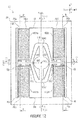
- the overall system has a parasitic and undesired mode in operation, which is very close to the "one-node-mode" EP 2233 961 A1 presented device difficult.
- Fig. 12 shows a figure EP 2233 961 A1 .
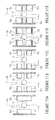
- the Figures 13a and 13b show recordings of such a micromirror whose spring elements have defects.
- a cascaded oscillator system is constructed from multiple vibrational frames.
- the vibration frames are formed from the piezoelectric actuators, which in turn are connected to the centrally arranged micromirror and an outer frame in each case via wide torsion springs.
- a disadvantage of this solution is on the one hand an increased space requirement, since the dimensions of the individual components are due to the formation of a double frame and the large width of the springs are correspondingly large, and a relatively low energy efficiency of the structure, since both ends of the piezoelectric actuators movably mounted are so that the force generated by the actuators can not be completely transferred to the micromirror or the torsion springs.
- the object of the present invention is therefore to provide a device with a vibratable suspended optical element, so that high material loads are avoided and a higher resonant frequency of the optical element is made possible, while allowing energy-efficient operation of the device by an optimal power flow.
- the core idea of the present invention is to have recognized that the above object can be achieved by virtue of the fact that actuators which are fixedly mounted on one side are connected via curved spring elements to the oscillatingly suspended micromirror.
- the curved spring elements allow absorption of forces such that a Material failure despite high operating frequencies and deflection amplitudes is prevented.
- an oscillatingly suspended micromirror is suspended via four torsion springs on two actuators, wherein the torsion springs are repeatedly curved and arranged at a distance to a torsion axis of the micromirror on the same, in order to allow large deflections of the micromirror by utilizing the lever law.
- torsion springs connecting the vibrationally suspended micromirror with actuators each suitably comprise a radius of curvature so that greater axial extension of the actuators is combined with efficient space utilization by the spring elements.
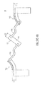
- Fig. 1 shows a curved torsion spring 14 which includes a longitudinal centerline 32 along the longitudinal extent of the spring. Starting from a first end of the longitudinal center line 32, the same comprises a curvature section 29, which comprises a curvature with a curvature radius r K1 about a curvature intermediate point 34 with an opening angle 31.
- the opening angle 31 includes, for example, approximately 90 °.
- the same comprises a curvature section 27, which has a curvature with a radius of curvature r K2 around a curvature center 35 with an opening angle 37 of, for example, 180 ° here.
- a region 39 is arranged in the direction of the second end of the longitudinal center line 32, in which the torsion spring 14 is straight and thus no Curvature includes, that is, has a curvature of zero or a radius of curvature infinity.
- the equal distributions of the sections 27 and 29 result in a uniform height of a base portion of a histogram of the torsion spring 14, whereas the portions in which the torsion spring includes no curvature and thus a constant local orientation to an additional amplitude of the histogram for the orientations of these sections.
- the radii of curvature r K1 ad and r K2 ad may have any relationship to each other, wherein the centers 34 and 35 of the radii of curvature are arranged in an alternating manner on each side along the course of the curved torsion spring 14.
- a center of curvature arranged on an alternating side to an adjacent center of curvature corresponds to an alternating change of sign of the radius of curvature along the course of the longitudinal center line.
- each with a center are arranged on alternate sides along the longitudinal center line, also only a radius of curvature or any, greater number of radii of curvature along the longitudinal center line may be arranged, embodiments describe torsion springs having less than ten sign changes the radii of curvature.
- the spring element 14 may be formed as a torsion spring.
- each curved spring element 14 of a device may be shaped such that local radii of curvature r K1 r K2 along the longitudinal centerline 32 have fewer than 10 sign changes.
- the opening angles 31 and 37 in combination with the centers of curvature 34 and 35 and the radii of curvature r K1 and r K2, describe opening angles of circular sectors along which the curves pass, the opening angles being less than or equal to 180 °.
- the actuators 16a and / or 16b may also comprise thermal actuators.
- the curved torsion spring 14 has the profile of a circular arc in the case of a single center of curvature and an S-shaped profile in the case of a plurality of centers of curvature.
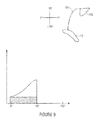
- Fig. 2 shows a histogram of the local orientation of a curved torsion spring 14
- Fig. 1 is formed starting from the section 39 in the orientation -90 °, which is shown in the histogram with the surface 39 '.
- the local orientation is constant over the longitudinal extent, so that the length of section 39 is arranged proportionally with the orientation -90 ° in the histogram.
- the subsequent right-hand curvature of the torsion spring towards the + 90 ° orientation leads in the histogram to a hatched area 27 'which is hatched and which corresponds to the uniform distribution of the local orientations along the section 27 of the torsion spring 14.
- the left-hand curvature following section 29 in the further course of spring along the section 29 from the orientation + 90 ° to 0 ° leads to the unshaded surface 29 'between 0 ° and + 90 ° in the histogram.
- the span of the histogram is, according to the minimum of -90 ° and the maximum of + 90 ° of the local orientations of the torsion spring in the range, an interval of 180 °.
- the interval is contiguously shaped, since each local orientation is formed between -90 ° and + 90 ° in the course of the curved torsion spring 14, whereby, as the hatched base portion 27 'of the histogram represents, an at least 10 percent portion of the histogram uniformly distributed between the minimum local orientation-90 ° and a maximum local orientation of + 90 ° is distributed.
- Alternative embodiments have curved torsion springs with only one or more radii of curvature, so that their span of the histograms is greater than 60 ° and less than 360 °. This means that a span of the histogram can be in the range of ⁇ 60 ° to ⁇ 360 °.
- Fig. 3 shows a device 10 with a vibrantly suspended (micro) mirror 12, which is suspended centrally via four curved torsion springs 14a-d to two actuators 16a and 16b.
- the actuators 16a and 16b are each firmly clamped on one side and arranged such that a deflectable end of the actuators faces the micromirror 12.
- the actuators 16a and 16b are designed as piezoactuators and each comprise a substrate and a piezoelectric functional layer arranged thereon, so that the actuators 16a and 16b are designed as bending beams.
- An activation of an actuator 16a or 16b leads to a deflection of the deflectable end facing the fixed clamped side in the direction out of the viewing plane, as shown graphically below.
- the micromirror 12 tilts about a torsion axis 18. If the actuators however, operated in phase, so a movement of the micromirror 12 out of the plane of the torsion axis 18 out.
- the actuators 16a and 16b, the micromirror 12 and the curved torsion springs 14a-d form a spring-mass system with a common resonance frequency.
- the actuators 16a and 16b are arranged symmetrically about the torsion axis 18, whereby a likewise symmetrical tilting of the micromirror 12 about the torsion axis 18 is achieved.
- the curved torsion springs 14a-d are connected to the actuators 16a and 16b.
- the ends of the curved torsion springs 14a-d facing away from the actuators 16a and 16b are connected to the micromirror 12 at mirror attachment locations 24a-d.
- both the actuator mounting locations 22a-d and the mirror mounting locations 24a-d are designed such that the transitions from the curved torsion springs 14a-d to the actuators 16a-b and from the curved torsion springs 14a-d to the micromirror 12 are rounded Outside edges of the respective curved spring element 14a-d are guided tangentially to the actuator 16a or 16b or the micromirror 12, and an edged or unsteady transition between the elements is avoided.
- the curved course of the torsion springs 14a-d allows an embodiment of the springs, which is provided with a greater longitudinal extent with respect to straight spring elements, so that forces induced by deformation in the material of the springs are distributed over a larger area of material.
- a constant transition of the different radii of curvature leads in contrast to angular and thus unsteady deflected torsion springs to avoid force peaks at the points of discontinuity.
- a rounded transition between the actuator / spring / spring / micromirror elements reduces the occurrence of force peaks in the material during deformation and avoids excessive material fatigue at these locations. For an additional increased operating time of the device is achieved.
- the actuator mounting locations 22a-d are positioned relative to one another such that the actuator mounting locations 22a and 22b and the actuator mounting locations 22c and 22d are disposed in pairs on a line 26a and 26b, respectively 26a and 26b extend parallel to the torsion axis 18.
- a minimization of not leading to the torsion axis 18 movements of the micromirror 12 is achieved.
- the actuators 16a and 16b may be formed such that a longitudinal dimension x 1 of the actuators 16a and 16b is larger than a radius of the circular micromirror 12.
- An enlarged formation of the extension x 1 allows for a greater deflection of the deflectable end of the actuators and consequently the Actuator mounting locations 22a-d. This greater deflection creates greater material deformation, which is enabled by the design of the curved torsion springs 14a-d.
- the longitudinal dimension x 1 denotes a distance from the fixed clamping of an actuator 16 a or 16 b along an axis arranged perpendicular to the torsion axis 18 to an actuator mounting location 22 a-b, ie a dimension along an extension in which the actuators according to the embodiment as Bending beams curve.
- the mirror attachment locations 24a-d are arranged at a distance x 3 from the torsion axis 18.
- the distance x 3 generates a lever action such that one is by the actuators 16a and 16b are induced and transmitted through the curved torsion springs 14a-d deflection of the actuators 16a and discharged to an extent to the micro mirror 12 16b depends on the distance x 3 ,
- the micromirror 12 is in Fig. 1 round and formed with a constant radius r.
- an alternative micromirror comprises a different shape, for example an ellipse.
- the distance x 1 may be chosen to be greater than half of the longest distance of any two points of a major side of the micromirror 12. If the micromirror 12 is, as in FIG Fig. 1 Shown as a round element, half of the longest dimension of any two points corresponds to radius r.
- the leverage-defining distance x 3 allows compared to an arrangement of torsion springs in the torsion with the same force of the actuators 16a and 16b a greater deflection of the micromirror 12 respectively an identical deflection of the micromirror 12 at a lower Aktuatorausschung.
- the distance x 2 is then determined as the distance between two Aktuatoranbringungsorte in a half plane defined by the torsion axis or the axis of symmetry.
- Fig. 4a shows a side view of the device 10 in an undeflected state.
- the actuators 16a and 16b are analog Fig. 3 each formed as a substrate 28a and 28b and a piezoelectric functional layer comprising piezo actuators.
- the actuators 16a and 16b comprise a thickness H 1 which is in a defined relationship to a thickness H 2 of the micromirror 12, the ratio of H 1 and H 2 being approximately equal to 1: 1.
- Alternative embodiments include a ratio H 1 and H 2 between 0.1 and 2.
- the substrate 28a and 28b of the actuators 16a and 16b, the curved torsion springs 14a and 14b, and the micromirror 12 may, as exemplified in FIG Fig. 4a and 4b represented, may be formed from the same material and in one piece, wherein the integral formation can be carried out for example by means of a timed etching process or a ⁇ tzstopp harsh from a common output carrier.
- the substrate 33 to which the actuators 16a and 16b are suspended is also integrally formed with the substrates 28a and 28b of the actuators 16a and 16b and hence the curved torsion springs 14a and 14b and the micromirror 12 such that, for example, the timed etching process Volume components of a portion of a wafer at laterally and axially different locations removed, wherein the structures of the substrate 28a and 28b of the actuators 16a and 16b, the curved torsion springs 14a and 14b and the micromirror 12 as the substrate 33 are formed from the portion of the wafer.
- the curved spring elements 14a and 14b and the oscillatingly suspended optical element (micromirrors) 12 can be formed in one piece from the substrate 33, from which a bearing is also formed, on which the actuators 16a and 16b are fixedly mounted.
- Fig. 4b shows device 10 in a deflected state in which the actuator 16a is deflected in one direction and the actuator 16b in an opposite direction.
- the deflection of the actuators 16a and 16b leads to a deformation of the curved torsion springs 14a and 14b and to a tilting of the micromirror 12 about the torsion axis 18.
- Fig. 5 shows a part of the Fig. 1 with a view of the mounting locations 22a and 24a, which connect the torsion spring 14a tangentially with the micromirror 12 and the actuator 16a, and the course of the curved torsion spring 14a.
- a longitudinal center line 32a of the curved torsion spring 14a has along its steady course of the just-shaped portion 39a and two bent portions 27a and 29a, which each have a constant radius of curvature r K 1 a and comprise r K2 a and a center of curvature 34a or 35a.
- the local radii of curvature r K1 a and r K2a may be formed such that they are each greater than half the mean width of the curved torsion spring and at the same time in each curvature portion 27a and 29a, the average of the amount of the respective radius of curvature r K1 a or r K2 a is smaller than 10 times the entire length of the longitudinal center line 32a.
- each curved spring element 14a and 14b may be shaped such that a local radius of curvature r K1 or r K2 of the longitudinal centerline 32 is more than half the average width of the respective curved spring element 14a or 14b over a length of the longitudinal centerline 32.
- each curved spring element 14a and 14b may be shaped such that an average of the magnitude of the radius of curvature r K1 or r K2 is smaller over portions 27 and / or 29 of the longitudinal centerline 32 in which the respective spring element 14a and 14b is curved than 10 times the length of the longitudinal centerline 32.
- An oscillatable suspended optical element for example a micromirror
- Fig. 6 shows a plan view of a device 20, in the device 10 is extended to the effect that two straight guided torsion springs 36a and 36b are arranged on the micromirror 12, the micromirror 12 facing away from the end is arranged at an immovable anchor point and their longitudinal course congruent with the torsion axis 18 extends.
- the straight torsion springs 36a and 36b have no direct connection to the curved torsion springs 14a-d.
- the straight torsion springs 36a and 36b are formed to stabilize the tilt of the micromirror 12.
- Fig. 7 shows a plan view of a device 30, in which the micromirror 12 is arranged on the actuators 16a and 16b via four curved torsion springs 14a-d.
- the curved torsion springs 14a-d are shaped such that in each case two curved torsion springs 14a and 14c and 14b and 14d arranged on one side of an axis of symmetry 41, which is perpendicular to the torsion axis 18, comprise a common section 38a and 38b of the torsion springs.
- the curved torsion springs 14a-d extend in a curved course toward the torsion axis 18, wherein the torsion axis 18, the curved torsion spring 14a with the curved torsion spring 14c and the curved torsion spring 14b is merged with the curved torsion spring 14d and the just formed further course 38a of the curved torsion springs 14a and 14c and the further, straight course 38b of the curved torsion springs 14b and 14d form.
- the distance x 3 from device 10 in FIG Fig. 1 is designed with a zero expansion.
- FIG. 8 shows a second embodiment of a torsion spring.
- a device 40 comprising simply curved torsion springs 42a-d connecting the micromirror 12 to the actuators 16a and 16b such that excitation induced by the actuators 16a and 16b tilts the micromirror 12 about the torsion axis 18 or along a plane the torsion axis 18 includes, moves.
- the single-curved torsion springs 42a-d are connected to the micromirror 12 at mirror attachment locations 44a-d.
- the mirror attachment locations 44a-d are rounded in a manner analogous to the mirror attachment locations of previous exemplary embodiments, so that tips occurring with respect to material stresses on structural transitions between the single-curved torsion springs 42a-d and the micromirror 12 are minimized.
- a lateral distance x 2 between the actuator mounting locations 46a and 46b and between 46c and 46d is greater than 150% of the maximum distance of any two points on a major side of the micromirror 12.
- a larger dimension x 2 results in a greater deflecting force and hence a faster one deflection of the micromirror 12. This means that the distance is more than 150% of the greatest distance of any two points of a page of the optical element may be 12 x 2 between the fastening locations 46a-d of an actuator 16a or 16b.
- actuator attachment locations 46a-d of the single-curved torsion springs 42a-d are also rounded or tangentially guided to the actuators 16a and 16b. All of the radii of curvature of the single-curved torsion springs 42a-d are along a continuous longitudinal centerline of the single-curved torsion springs 42a-d on the same side of the longitudinal centerline, with an average of each radius of curvature less than 10 times the length of the longitudinal centerline. As a result, the single-curved torsion springs 42a-d are designed such that their course corresponds approximately to a quarter ellipse.
- each curved spring element 42a-d can be shaped so that an average of the radius of curvature r K1 or r K2 over sections 27a, 29a and / or 39a of the longitudinal center line 32, in which the respective spring element 42a-d is curved, is less than 10 times the length of the longitudinal center line 42a-d.
- Alternative embodiments show simply curved torsion springs whose course corresponds approximately to a circular arc.
- the curves of the single-curved torsion springs along their course comprise one or more radii of curvature about one or more centers of curvature, all centers of curvature being located on the same side of the longitudinal center line of the respective single curved torsion spring and each local radius of curvature being greater in magnitude over a length of the center line than half of a mean width of the respective single curved torsion spring.
- the arrangement of single-curved torsion springs can be advantageous over the arrangement of curved torsion springs of the preceding embodiments.
- the curvature of the single-curved torsion springs 42a-d is designed such that the single-curved torsion springs 42a-d project from the actuator attachment locations 46a-d comprise only portions which, with the exception of the Aktuatoranbringungsorte 46a-d, only point in the direction of the micromirror 12 and describe a curvature in the direction of the micromirror 12.
- the curved torsion springs 14 were configured such that portions of the curved torsion springs 14a-d point away from the micromirror 12 from actuator mounting locations 22a-d and define a maximum lateral extent in the direction of the torsion axis 18 by the lateral extent of the curved torsion springs 14a-d becomes.
- the maximum lateral space in the direction of the torsion axis 18 of the device 40 is defined by the lateral extent of the actuators 16a and 16b.
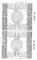
- FIG. 12 shows a histogram of the curvatures of the single-curved torsion spring 42 c of the device 40 Fig. 8 Starting from the actuator 16b in the direction of the micromirror 12. Starting from the tangential arrangement of the single-curved torsion spring 42c on the actuator 16b with the local orientation 0 °, the curvature of the single-curved torsion spring 42c is continuous towards an orientation of + 90 °. From a minimum orientation of 0 ° to a maximum orientation of + 90 °, the histogram includes a span of 90 °. At least 10% of the integral area of the histogram in Fig.
- each curved spring element 42a-d may be shaped such that the local orientation along the longitudinal centerline 32 has a steady course.
- Alternative embodiments comprise simply curved torsion springs, the histograms of which span greater than or equal to 60 ° and less than or equal to 270 °. This means that the span of the histogram can be in the range of ⁇ 60 ° to ⁇ 270 °.
- Fig. 10 shows a schematic plan view of a device 60, which includes a micromirror 12, which is arranged on the actuators 16a and 16b via four single-curved torsion springs 42a-d.
- curved torsion springs 14a-d which support a deflection of the actuators 16a and 16b relative to the substrate 33, are arranged on the actuators 16a and 16b.
- the curved torsion springs 14a and 14c and 14b and 14d are pairs and analog Fig. 5 the common portions 38a and 38b of the curved torsion springs.
- the ends of the curved torsion springs 14a-d facing away from the actuators 16a and 16b can also be arranged on further actuators so that the micromirror 12 is rotatable along a second axis different from the torsion axis 18 or movable along an axis perpendicular to the torsion axis 18 ,
- Fig. 11 schematically shows possible arrangements of actuators 16a-d with respect to the micromirror.
- Fig. 11a Analogous to the preceding embodiments, an arrangement of the actuators 16a and 16b symmetrically about the torsion axis 18.
- the actuators 16a and 16b are parallel and spaced from the torsion axis 18 on a side facing away from the micromirror 12 fixedly clamped and arranged symmetrically to the axis of symmetry 41.
- Fig. 11b shows an array of four actuators 16a-d, which are arranged both symmetrically to the torsion axis 18 and symmetrical to the axis of symmetry 41, so that in each case an actuator 16a-d in a quadrant of the torsion axis 18 and the axis of symmetry 41 spanned coordinate system is arranged.
- Fig. 11c shows an arrangement of actuators analog Fig. 11b in which an arrangement of further actuators is indicated by points between the actuators 16a and 16b and between the actuators 16c and 16d. Other actuators are arranged symmetrically to the axis of symmetry 41. If, for example, an additional fifth and sixth actuator are arranged, then Fig. 11b expanded so that the additional fifth and sixth actuator in the course of the axis of symmetry 41 are arranged.
- Fig. 11d shows an array of actuators 16a-d analog Fig. 11b , in which the actuators are firmly clamped in a course parallel to the axis of symmetry 41 and the freely deflectable ends of the actuators 16a-d face the axis of symmetry 41 and run parallel to the axis of symmetry 41.
- Fig. 11e shows an array of actuators 16a-d analog Fig. 11d , in which the fixed clamping of the actuators 16a-d faces the axis of symmetry 41 and the freely deflectable end of the actuators 16a-d of the symmetry axis 41 is arranged facing away.
- any number of actuators can be arranged, wherein the actuators are arranged both symmetrically to the torsion axis 18 and symmetrically to the axis of symmetry 41 perpendicular to the torsion axis 18 and intersect the axes of symmetry in the center of the micromirror 12.
- the described embodiments provide an oscillating system comprising a micromirror and external piezoelectric actuators.
- the actuators can be designed such that they comprise higher resonance frequencies than the micromirror, so that a use of a larger layer thickness of the actuators is made possible and the larger layer thickness makes the overall structure more robust.
- the actuators can be operated in the zero-node mode, the first eigenmode of a bending beam.
- adjacent parasitic modes are relatively widely spaced in the frequency range, so that the eigenmode is dominant and an influence of parasitic modes which limits the operation of the micromirror is reduced.
- discontinuous material gradients of torsion springs such as in the in Fig. 13 shown torsion springs, which are formed with a 90 ° angle, avoided by the curved and simply curved torsion springs have a steady course and thus force peaks and mechanically overloaded points along the course of the curved and simply curved torsion springs are prevented.
- Rounded or tangentially configured attachment locations of the springs on the micromirror and / or the actuators also prevent mechanically overloaded points at the ends of the torsion springs.
- the micromirror system described has a high resonance frequency, which is designed to be stable and robust. If the torsion springs are arranged at a distance from the torsion axis on the micromirror, the lever law is usable in that the distance from the torsion axis to the mirror mounting locations acts as a lever arm and the force of the actuators is transmitted efficiently, whereby a large displacement of the micromirror is achieved can.
- the use of torsion springs as Lever prevented by the design of the torsion springs and the mounting locations of actuators and micromirror at the same time places with excessive mechanical stress.
Landscapes
- Physics & Mathematics (AREA)
- Engineering & Computer Science (AREA)
- Computer Hardware Design (AREA)
- Microelectronics & Electronic Packaging (AREA)
- General Physics & Mathematics (AREA)
- Optics & Photonics (AREA)
- Micromachines (AREA)
- Mechanical Optical Scanning Systems (AREA)
- Mechanical Light Control Or Optical Switches (AREA)
Applications Claiming Priority (1)
| Application Number | Priority Date | Filing Date | Title |
|---|---|---|---|
| DE102013209234.2A DE102013209234B4 (de) | 2013-05-17 | 2013-05-17 | Vorrichtung mit einem schwingfähig aufgehängten optischen Element |
Publications (2)
| Publication Number | Publication Date |
|---|---|
| EP2803633A1 true EP2803633A1 (fr) | 2014-11-19 |
| EP2803633B1 EP2803633B1 (fr) | 2015-08-19 |
Family
ID=50721635
Family Applications (1)
| Application Number | Title | Priority Date | Filing Date |
|---|---|---|---|
| EP14168396.1A Active EP2803633B1 (fr) | 2013-05-17 | 2014-05-15 | Dispositif doté d'un élément optique suspendu pivotant |
Country Status (4)
| Country | Link |
|---|---|
| US (1) | US9733470B2 (fr) |
| EP (1) | EP2803633B1 (fr) |
| CN (1) | CN104166232B (fr) |
| DE (1) | DE102013209234B4 (fr) |
Cited By (2)
| Publication number | Priority date | Publication date | Assignee | Title |
|---|---|---|---|---|
| DE102014217798A1 (de) * | 2014-09-05 | 2016-03-10 | Fraunhofer-Gesellschaft zur Förderung der angewandten Forschung e.V. | Mikromechanische piezoelektrische Aktuatoren zur Realisierung hoher Kräfte und Auslenkungen |
| DE102018209886A1 (de) | 2018-06-19 | 2019-12-19 | Fraunhofer-Gesellschaft zur Förderung der angewandten Forschung e.V. | Einrichtung zur Projektion eines Laserstrahls zur Erzeugung eines Bildes auf der Netzhaut eines Auges und Brilleneinrichtung mit zwei derartigen Einrichtungen |
Families Citing this family (15)
| Publication number | Priority date | Publication date | Assignee | Title |
|---|---|---|---|---|
| JP5860066B2 (ja) * | 2012-01-24 | 2016-02-16 | パイオニア株式会社 | アクチュエータ |
| DE102014211027A1 (de) * | 2014-06-10 | 2015-12-17 | Robert Bosch Gmbh | Mikromechanisches Bauteil und Herstellungsverfahren für ein mikromechanisches Bauteil |
| IT201700043616A1 (it) | 2017-04-20 | 2018-10-20 | St Microelectronics Srl | Struttura oscillante con ridotta deformazione dinamica, dispositivo ottico includente la struttura oscillante, e metodo di fabbricazione della struttura oscillante |
| EP3719558B1 (fr) * | 2017-12-01 | 2024-03-20 | Hamamatsu Photonics K.K. | Dispositif d'actionneur |
| JP6585147B2 (ja) | 2017-12-01 | 2019-10-02 | 浜松ホトニクス株式会社 | アクチュエータ装置 |
| US11815738B2 (en) | 2018-01-12 | 2023-11-14 | Barco N.V. | Device for elastic pivoting about two orthogonal axes |
| DE102018220422A1 (de) * | 2018-11-28 | 2020-05-28 | Robert Bosch Gmbh | Aktuationseinrichtung für ein mikromechanisches Bauelement, mikromechanisches Bauelement und Verfahren zum Herstellen eines mikromechanisches Bauelements |
| DE102019202658B3 (de) | 2019-02-27 | 2020-06-04 | Fraunhofer-Gesellschaft zur Förderung der angewandten Forschung e.V. | Mikromechanische Struktur und Verfahren zum Bereitstellen derselben |
| WO2020173919A2 (fr) | 2019-02-27 | 2020-09-03 | Fraunhofer-Gesellschaft zur Förderung der angewandten Forschung e.V. | Structure micromécanique, système micromécanique et procédé pour fournir une structure micromécanique |
| US11221478B2 (en) * | 2019-04-15 | 2022-01-11 | Microsoft Technology Licensing, Llc | MEMS scanner |
| US11175491B2 (en) | 2019-04-25 | 2021-11-16 | Microsoft Technology Licensing, Llc | Non-resonant microelectromechanical systems scanner with piezoelectric actuators |
| US11649158B2 (en) * | 2019-07-22 | 2023-05-16 | Rosemount Aerospace Inc. | Piezoelectric MEMS device with cantilever structures |
| US11434130B2 (en) * | 2019-12-31 | 2022-09-06 | Texas Instruments Incorporated | Surface micromachined structures |
| US11693233B2 (en) | 2020-06-19 | 2023-07-04 | Microsoft Technology Licensing, Llc | Microelectromechanical system (MEMS) scanner having actuator pairs cantilevered adjacent to opposite sides of a scanning mirror |
| CN114063238A (zh) * | 2020-07-31 | 2022-02-18 | 奥普托图尼股份公司 | 光学装置、制造光学装置的方法和操作光学装置的方法 |
Citations (5)
| Publication number | Priority date | Publication date | Assignee | Title |
|---|---|---|---|---|
| US6198565B1 (en) | 1998-11-16 | 2001-03-06 | Victor Company Of Japan, Limited | Light deflection element and display apparatus using same |
| US6657764B1 (en) | 1999-03-18 | 2003-12-02 | The Trustees Of Boston University | Very large angle integrated optical scanner made with an array of piezoelectric monomorphs |
| US7190502B2 (en) | 2003-09-08 | 2007-03-13 | Commissariat A L'energie Atomique | Oscillating micromirror with bimorph actuation |
| EP2233961A1 (fr) | 2008-01-10 | 2010-09-29 | Konica Minolta Opto, Inc. | Micro-scanner et procede de commande associe |
| US8125699B2 (en) | 2006-09-27 | 2012-02-28 | National Institute Of Advanced Industrial Science And Technology | Optical scanning device |
Family Cites Families (11)
| Publication number | Priority date | Publication date | Assignee | Title |
|---|---|---|---|---|
| JPH11211970A (ja) * | 1998-01-27 | 1999-08-06 | Olympus Optical Co Ltd | 光学系可動部の支持バネ装置 |
| US6836366B1 (en) | 2000-03-03 | 2004-12-28 | Axsun Technologies, Inc. | Integrated tunable fabry-perot filter and method of making same |
| AU7289801A (en) | 2000-04-11 | 2001-10-23 | Sandia Corp | Microelectromechanical apparatus for elevating and tilting a platform |
| US6632373B1 (en) | 2000-09-28 | 2003-10-14 | Xerox Corporation | Method for an optical switch on a substrate |
| WO2002079853A1 (fr) | 2001-03-16 | 2002-10-10 | Corning Intellisense Corporation | Dispositifs mecaniques microelectriques a actionnement electrostatique et procede de fabrication |
| JP4724308B2 (ja) * | 2001-04-17 | 2011-07-13 | オリンパス株式会社 | ガルバノミラー |
| US7091057B2 (en) | 2003-12-19 | 2006-08-15 | Agency For Science, Technology And Research | Method of making a single-crystal-silicon 3D micromirror |
| FR2864526B1 (fr) | 2003-12-26 | 2006-10-13 | Commissariat Energie Atomique | Dispositif d'actionnement electrostatique |
| CN201621218U (zh) * | 2009-09-29 | 2010-11-03 | 比亚迪股份有限公司 | 弹簧及组合弹簧 |
| DE102010028111B4 (de) | 2010-04-22 | 2016-01-21 | Technische Universität Dresden | Mikromechanisches Element |
| JP5323155B2 (ja) | 2011-09-08 | 2013-10-23 | 富士フイルム株式会社 | ミラー駆動装置及びその駆動方法並びに製造方法 |
-
2013
- 2013-05-17 DE DE102013209234.2A patent/DE102013209234B4/de active Active
-
2014
- 2014-05-15 EP EP14168396.1A patent/EP2803633B1/fr active Active
- 2014-05-16 US US14/280,487 patent/US9733470B2/en active Active
- 2014-05-19 CN CN201410211576.2A patent/CN104166232B/zh active Active
Patent Citations (5)
| Publication number | Priority date | Publication date | Assignee | Title |
|---|---|---|---|---|
| US6198565B1 (en) | 1998-11-16 | 2001-03-06 | Victor Company Of Japan, Limited | Light deflection element and display apparatus using same |
| US6657764B1 (en) | 1999-03-18 | 2003-12-02 | The Trustees Of Boston University | Very large angle integrated optical scanner made with an array of piezoelectric monomorphs |
| US7190502B2 (en) | 2003-09-08 | 2007-03-13 | Commissariat A L'energie Atomique | Oscillating micromirror with bimorph actuation |
| US8125699B2 (en) | 2006-09-27 | 2012-02-28 | National Institute Of Advanced Industrial Science And Technology | Optical scanning device |
| EP2233961A1 (fr) | 2008-01-10 | 2010-09-29 | Konica Minolta Opto, Inc. | Micro-scanner et procede de commande associe |
Cited By (5)
| Publication number | Priority date | Publication date | Assignee | Title |
|---|---|---|---|---|
| DE102014217798A1 (de) * | 2014-09-05 | 2016-03-10 | Fraunhofer-Gesellschaft zur Förderung der angewandten Forschung e.V. | Mikromechanische piezoelektrische Aktuatoren zur Realisierung hoher Kräfte und Auslenkungen |
| US10349182B2 (en) | 2014-09-05 | 2019-07-09 | Fraunhofer-Gesellschaft Zur Foerderung Der Angewandten Forschung E.V. | Micromechanical piezoelectric actuators for implementing large forces and deflections |
| DE102018209886A1 (de) | 2018-06-19 | 2019-12-19 | Fraunhofer-Gesellschaft zur Förderung der angewandten Forschung e.V. | Einrichtung zur Projektion eines Laserstrahls zur Erzeugung eines Bildes auf der Netzhaut eines Auges und Brilleneinrichtung mit zwei derartigen Einrichtungen |
| WO2019243395A1 (fr) | 2018-06-19 | 2019-12-26 | Fraunhofer-Gesellschaft zur Förderung der angewandten Forschung e.V. | Dispositif de projection d'un faisceau laser pour produire une image sur la rétine d'un œil |
| US11867916B2 (en) | 2018-06-19 | 2024-01-09 | Fraunhofer-Gesellschaft zur Förderung der angewandten Forschung e.V. | Device apparatus for projecting a laser beam for generating an image on the retina of an eye |
Also Published As
| Publication number | Publication date |
|---|---|
| DE102013209234B4 (de) | 2018-04-05 |
| DE102013209234A1 (de) | 2014-11-20 |
| US20140340726A1 (en) | 2014-11-20 |
| EP2803633B1 (fr) | 2015-08-19 |
| US9733470B2 (en) | 2017-08-15 |
| CN104166232A (zh) | 2014-11-26 |
| CN104166232B (zh) | 2017-05-17 |
Similar Documents
| Publication | Publication Date | Title |
|---|---|---|
| EP2803633B1 (fr) | Dispositif doté d'un élément optique suspendu pivotant | |
| EP1212650B1 (fr) | Dispositif a micro-oscillations | |
| EP2183548B1 (fr) | Capteur micromécanique de vitesse de rotation | |
| DE19643182B4 (de) | Schwingungskonstruktion | |
| EP3610315B1 (fr) | Dispositif de miroirs micromécanique | |
| DE102011089514B4 (de) | Mikrospiegel und 2-Spiegelsystem | |
| EP2577090B1 (fr) | Générateur de force à monter sur une structure | |
| EP0436532A1 (fr) | Entrainement a oscillation de rotation | |
| DE3530057C2 (fr) | ||
| DE112016001732T5 (de) | Optische abtastvorrichtung | |
| DE102018216611B4 (de) | MEMS-Bauelement mit Aufhängungsstruktur und Verfahren zum Herstellen eines MEMS-Bauelementes | |
| DE102017219442A1 (de) | Spiegelvorrichtung, die eine Blattfeder mit Öffnungen aufweist | |
| DE102005034927A1 (de) | Gelenkkonstruktion für eine Mikrospiegelvorrichtung | |
| DE102012219591B4 (de) | Mikromechanisches Bauteil, Herstellungsverfahren für ein mikromechanisches Bauteil und Verfahren zum Betreiben eines mikromechanischen Bauteils | |
| DE02764289T1 (de) | Rotorsystemschwingungsdämpfer | |
| EP1535027B1 (fr) | Detecteur de vitesses de rotation | |
| DE102015209030B4 (de) | Mikromechanische Vorrichtung und Verfahren zum Herstellen einer mikromechanischen Vorrichtung | |
| EP0639759B1 (fr) | Lame vibrante de mesure, plat et monopièce, à deux noeuds, pour la mesure de déplacement ou de force | |
| WO2017084918A1 (fr) | Capteur de vitesse de lacet micromécanique et son procédé de fonctionnement | |
| DE102013223937B4 (de) | Mikrospiegelanordnung | |
| DE60126484T2 (de) | Vibrationsstruktur mit zwei gekoppelten oszillatoren, insbesondere für einen kreisel | |
| DE4236574C2 (de) | Linearaktuator | |
| EP3818201B1 (fr) | Élément cardant | |
| WO2021078487A1 (fr) | Système d'oscillateur micromécanique | |
| DE102023204632A1 (de) | MEMS-Gyroskop, das Drehungen in einer Ebene erfasst |
Legal Events
| Date | Code | Title | Description |
|---|---|---|---|
| PUAI | Public reference made under article 153(3) epc to a published international application that has entered the european phase |
Free format text: ORIGINAL CODE: 0009012 |
|
| 17P | Request for examination filed |
Effective date: 20140515 |
|
| AK | Designated contracting states |
Kind code of ref document: A1 Designated state(s): AL AT BE BG CH CY CZ DE DK EE ES FI FR GB GR HR HU IE IS IT LI LT LU LV MC MK MT NL NO PL PT RO RS SE SI SK SM TR |
|
| AX | Request for extension of the european patent |
Extension state: BA ME |
|
| R17P | Request for examination filed (corrected) |
Effective date: 20150204 |
|
| RBV | Designated contracting states (corrected) |
Designated state(s): AL AT BE BG CH CY CZ DE DK EE ES FI FR GB GR HR HU IE IS IT LI LT LU LV MC MK MT NL NO PL PT RO RS SE SI SK SM TR |
|
| GRAP | Despatch of communication of intention to grant a patent |
Free format text: ORIGINAL CODE: EPIDOSNIGR1 |
|
| INTG | Intention to grant announced |
Effective date: 20150331 |
|
| GRAS | Grant fee paid |
Free format text: ORIGINAL CODE: EPIDOSNIGR3 |
|
| GRAA | (expected) grant |
Free format text: ORIGINAL CODE: 0009210 |
|
| AK | Designated contracting states |
Kind code of ref document: B1 Designated state(s): AL AT BE BG CH CY CZ DE DK EE ES FI FR GB GR HR HU IE IS IT LI LT LU LV MC MK MT NL NO PL PT RO RS SE SI SK SM TR |
|
| REG | Reference to a national code |
Ref country code: GB Ref legal event code: FG4D Free format text: NOT ENGLISH |
|
| REG | Reference to a national code |
Ref country code: CH Ref legal event code: EP |
|
| REG | Reference to a national code |
Ref country code: IE Ref legal event code: FG4D Free format text: LANGUAGE OF EP DOCUMENT: GERMAN |
|
| REG | Reference to a national code |
Ref country code: AT Ref legal event code: REF Ref document number: 743644 Country of ref document: AT Kind code of ref document: T Effective date: 20150915 |
|
| REG | Reference to a national code |
Ref country code: DE Ref legal event code: R096 Ref document number: 502014000077 Country of ref document: DE |
|
| REG | Reference to a national code |
Ref country code: LT Ref legal event code: MG4D |
|
| REG | Reference to a national code |
Ref country code: NL Ref legal event code: MP Effective date: 20150819 |
|
| PG25 | Lapsed in a contracting state [announced via postgrant information from national office to epo] |
Ref country code: LV Free format text: LAPSE BECAUSE OF FAILURE TO SUBMIT A TRANSLATION OF THE DESCRIPTION OR TO PAY THE FEE WITHIN THE PRESCRIBED TIME-LIMIT Effective date: 20150819 Ref country code: NO Free format text: LAPSE BECAUSE OF FAILURE TO SUBMIT A TRANSLATION OF THE DESCRIPTION OR TO PAY THE FEE WITHIN THE PRESCRIBED TIME-LIMIT Effective date: 20151119 Ref country code: FI Free format text: LAPSE BECAUSE OF FAILURE TO SUBMIT A TRANSLATION OF THE DESCRIPTION OR TO PAY THE FEE WITHIN THE PRESCRIBED TIME-LIMIT Effective date: 20150819 Ref country code: LT Free format text: LAPSE BECAUSE OF FAILURE TO SUBMIT A TRANSLATION OF THE DESCRIPTION OR TO PAY THE FEE WITHIN THE PRESCRIBED TIME-LIMIT Effective date: 20150819 Ref country code: GR Free format text: LAPSE BECAUSE OF FAILURE TO SUBMIT A TRANSLATION OF THE DESCRIPTION OR TO PAY THE FEE WITHIN THE PRESCRIBED TIME-LIMIT Effective date: 20151120 |
|
| PG25 | Lapsed in a contracting state [announced via postgrant information from national office to epo] |
Ref country code: PT Free format text: LAPSE BECAUSE OF FAILURE TO SUBMIT A TRANSLATION OF THE DESCRIPTION OR TO PAY THE FEE WITHIN THE PRESCRIBED TIME-LIMIT Effective date: 20151221 Ref country code: SE Free format text: LAPSE BECAUSE OF FAILURE TO SUBMIT A TRANSLATION OF THE DESCRIPTION OR TO PAY THE FEE WITHIN THE PRESCRIBED TIME-LIMIT Effective date: 20150819 Ref country code: RS Free format text: LAPSE BECAUSE OF FAILURE TO SUBMIT A TRANSLATION OF THE DESCRIPTION OR TO PAY THE FEE WITHIN THE PRESCRIBED TIME-LIMIT Effective date: 20150819 Ref country code: IS Free format text: LAPSE BECAUSE OF FAILURE TO SUBMIT A TRANSLATION OF THE DESCRIPTION OR TO PAY THE FEE WITHIN THE PRESCRIBED TIME-LIMIT Effective date: 20151219 Ref country code: PL Free format text: LAPSE BECAUSE OF FAILURE TO SUBMIT A TRANSLATION OF THE DESCRIPTION OR TO PAY THE FEE WITHIN THE PRESCRIBED TIME-LIMIT Effective date: 20150819 Ref country code: ES Free format text: LAPSE BECAUSE OF FAILURE TO SUBMIT A TRANSLATION OF THE DESCRIPTION OR TO PAY THE FEE WITHIN THE PRESCRIBED TIME-LIMIT Effective date: 20150819 |
|
| PG25 | Lapsed in a contracting state [announced via postgrant information from national office to epo] |
Ref country code: NL Free format text: LAPSE BECAUSE OF FAILURE TO SUBMIT A TRANSLATION OF THE DESCRIPTION OR TO PAY THE FEE WITHIN THE PRESCRIBED TIME-LIMIT Effective date: 20150819 |
|
| PG25 | Lapsed in a contracting state [announced via postgrant information from national office to epo] |
Ref country code: DK Free format text: LAPSE BECAUSE OF FAILURE TO SUBMIT A TRANSLATION OF THE DESCRIPTION OR TO PAY THE FEE WITHIN THE PRESCRIBED TIME-LIMIT Effective date: 20150819 Ref country code: IT Free format text: LAPSE BECAUSE OF FAILURE TO SUBMIT A TRANSLATION OF THE DESCRIPTION OR TO PAY THE FEE WITHIN THE PRESCRIBED TIME-LIMIT Effective date: 20150819 Ref country code: EE Free format text: LAPSE BECAUSE OF FAILURE TO SUBMIT A TRANSLATION OF THE DESCRIPTION OR TO PAY THE FEE WITHIN THE PRESCRIBED TIME-LIMIT Effective date: 20150819 Ref country code: CZ Free format text: LAPSE BECAUSE OF FAILURE TO SUBMIT A TRANSLATION OF THE DESCRIPTION OR TO PAY THE FEE WITHIN THE PRESCRIBED TIME-LIMIT Effective date: 20150819 Ref country code: SK Free format text: LAPSE BECAUSE OF FAILURE TO SUBMIT A TRANSLATION OF THE DESCRIPTION OR TO PAY THE FEE WITHIN THE PRESCRIBED TIME-LIMIT Effective date: 20150819 |
|
| REG | Reference to a national code |
Ref country code: FR Ref legal event code: PLFP Year of fee payment: 3 |
|
| REG | Reference to a national code |
Ref country code: DE Ref legal event code: R097 Ref document number: 502014000077 Country of ref document: DE |
|
| PG25 | Lapsed in a contracting state [announced via postgrant information from national office to epo] |
Ref country code: RO Free format text: LAPSE BECAUSE OF FAILURE TO SUBMIT A TRANSLATION OF THE DESCRIPTION OR TO PAY THE FEE WITHIN THE PRESCRIBED TIME-LIMIT Effective date: 20150819 |
|
| PLBE | No opposition filed within time limit |
Free format text: ORIGINAL CODE: 0009261 |
|
| STAA | Information on the status of an ep patent application or granted ep patent |
Free format text: STATUS: NO OPPOSITION FILED WITHIN TIME LIMIT |
|
| 26N | No opposition filed |
Effective date: 20160520 |
|
| PG25 | Lapsed in a contracting state [announced via postgrant information from national office to epo] |
Ref country code: BE Free format text: LAPSE BECAUSE OF NON-PAYMENT OF DUE FEES Effective date: 20160531 Ref country code: SI Free format text: LAPSE BECAUSE OF FAILURE TO SUBMIT A TRANSLATION OF THE DESCRIPTION OR TO PAY THE FEE WITHIN THE PRESCRIBED TIME-LIMIT Effective date: 20150819 |
|
| PG25 | Lapsed in a contracting state [announced via postgrant information from national office to epo] |
Ref country code: LU Free format text: LAPSE BECAUSE OF FAILURE TO SUBMIT A TRANSLATION OF THE DESCRIPTION OR TO PAY THE FEE WITHIN THE PRESCRIBED TIME-LIMIT Effective date: 20160515 |
|
| REG | Reference to a national code |
Ref country code: IE Ref legal event code: MM4A |
|
| REG | Reference to a national code |
Ref country code: FR Ref legal event code: PLFP Year of fee payment: 4 |
|
| PG25 | Lapsed in a contracting state [announced via postgrant information from national office to epo] |
Ref country code: IE Free format text: LAPSE BECAUSE OF NON-PAYMENT OF DUE FEES Effective date: 20160515 |
|
| REG | Reference to a national code |
Ref country code: CH Ref legal event code: PL |
|
| PG25 | Lapsed in a contracting state [announced via postgrant information from national office to epo] |
Ref country code: LI Free format text: LAPSE BECAUSE OF NON-PAYMENT OF DUE FEES Effective date: 20170531 Ref country code: CH Free format text: LAPSE BECAUSE OF NON-PAYMENT OF DUE FEES Effective date: 20170531 |
|
| REG | Reference to a national code |
Ref country code: FR Ref legal event code: PLFP Year of fee payment: 5 |
|
| PG25 | Lapsed in a contracting state [announced via postgrant information from national office to epo] |
Ref country code: HU Free format text: LAPSE BECAUSE OF FAILURE TO SUBMIT A TRANSLATION OF THE DESCRIPTION OR TO PAY THE FEE WITHIN THE PRESCRIBED TIME-LIMIT; INVALID AB INITIO Effective date: 20140515 Ref country code: SM Free format text: LAPSE BECAUSE OF FAILURE TO SUBMIT A TRANSLATION OF THE DESCRIPTION OR TO PAY THE FEE WITHIN THE PRESCRIBED TIME-LIMIT Effective date: 20150819 |
|
| PG25 | Lapsed in a contracting state [announced via postgrant information from national office to epo] |
Ref country code: MT Free format text: LAPSE BECAUSE OF FAILURE TO SUBMIT A TRANSLATION OF THE DESCRIPTION OR TO PAY THE FEE WITHIN THE PRESCRIBED TIME-LIMIT Effective date: 20150819 Ref country code: MC Free format text: LAPSE BECAUSE OF FAILURE TO SUBMIT A TRANSLATION OF THE DESCRIPTION OR TO PAY THE FEE WITHIN THE PRESCRIBED TIME-LIMIT Effective date: 20150819 Ref country code: CY Free format text: LAPSE BECAUSE OF FAILURE TO SUBMIT A TRANSLATION OF THE DESCRIPTION OR TO PAY THE FEE WITHIN THE PRESCRIBED TIME-LIMIT Effective date: 20150819 Ref country code: HR Free format text: LAPSE BECAUSE OF FAILURE TO SUBMIT A TRANSLATION OF THE DESCRIPTION OR TO PAY THE FEE WITHIN THE PRESCRIBED TIME-LIMIT Effective date: 20150819 Ref country code: MK Free format text: LAPSE BECAUSE OF FAILURE TO SUBMIT A TRANSLATION OF THE DESCRIPTION OR TO PAY THE FEE WITHIN THE PRESCRIBED TIME-LIMIT Effective date: 20150819 |
|
| PG25 | Lapsed in a contracting state [announced via postgrant information from national office to epo] |
Ref country code: BG Free format text: LAPSE BECAUSE OF FAILURE TO SUBMIT A TRANSLATION OF THE DESCRIPTION OR TO PAY THE FEE WITHIN THE PRESCRIBED TIME-LIMIT Effective date: 20150819 |
|
| PG25 | Lapsed in a contracting state [announced via postgrant information from national office to epo] |
Ref country code: TR Free format text: LAPSE BECAUSE OF FAILURE TO SUBMIT A TRANSLATION OF THE DESCRIPTION OR TO PAY THE FEE WITHIN THE PRESCRIBED TIME-LIMIT Effective date: 20150819 Ref country code: AL Free format text: LAPSE BECAUSE OF FAILURE TO SUBMIT A TRANSLATION OF THE DESCRIPTION OR TO PAY THE FEE WITHIN THE PRESCRIBED TIME-LIMIT Effective date: 20150819 |
|
| REG | Reference to a national code |
Ref country code: AT Ref legal event code: MM01 Ref document number: 743644 Country of ref document: AT Kind code of ref document: T Effective date: 20190515 |
|
| PG25 | Lapsed in a contracting state [announced via postgrant information from national office to epo] |
Ref country code: AT Free format text: LAPSE BECAUSE OF NON-PAYMENT OF DUE FEES Effective date: 20190515 |
|
| P01 | Opt-out of the competence of the unified patent court (upc) registered |
Effective date: 20230524 |
|
| PGFP | Annual fee paid to national office [announced via postgrant information from national office to epo] |
Ref country code: GB Payment date: 20240522 Year of fee payment: 11 |
|
| PGFP | Annual fee paid to national office [announced via postgrant information from national office to epo] |
Ref country code: DE Payment date: 20240517 Year of fee payment: 11 |
|
| PGFP | Annual fee paid to national office [announced via postgrant information from national office to epo] |
Ref country code: FR Payment date: 20240522 Year of fee payment: 11 |