EP2803608B1 - Banknote store - Google Patents
Banknote store Download PDFInfo
- Publication number
- EP2803608B1 EP2803608B1 EP14172660.4A EP14172660A EP2803608B1 EP 2803608 B1 EP2803608 B1 EP 2803608B1 EP 14172660 A EP14172660 A EP 14172660A EP 2803608 B1 EP2803608 B1 EP 2803608B1
- Authority
- EP
- European Patent Office
- Prior art keywords
- drum
- winding means
- banknote
- banknotes
- winding
- Prior art date
- Legal status (The legal status is an assumption and is not a legal conclusion. Google has not performed a legal analysis and makes no representation as to the accuracy of the status listed.)
- Active
Links
- 238000004804 winding Methods 0.000 claims description 70
- 238000000034 method Methods 0.000 claims description 61
- 238000012544 monitoring process Methods 0.000 claims description 4
- 230000002093 peripheral effect Effects 0.000 claims description 3
- 230000008602 contraction Effects 0.000 claims description 2
- 238000005259 measurement Methods 0.000 description 11
- 230000007423 decrease Effects 0.000 description 6
- 230000008859 change Effects 0.000 description 4
- 230000008901 benefit Effects 0.000 description 3
- 230000001133 acceleration Effects 0.000 description 2
- 238000004364 calculation method Methods 0.000 description 2
- 230000008878 coupling Effects 0.000 description 2
- 238000010168 coupling process Methods 0.000 description 2
- 238000005859 coupling reaction Methods 0.000 description 2
- 238000004519 manufacturing process Methods 0.000 description 2
- 230000004048 modification Effects 0.000 description 2
- 238000012986 modification Methods 0.000 description 2
- 230000002441 reversible effect Effects 0.000 description 2
- 230000009471 action Effects 0.000 description 1
- 230000004075 alteration Effects 0.000 description 1
- 230000001419 dependent effect Effects 0.000 description 1
- 238000009795 derivation Methods 0.000 description 1
- 238000013461 design Methods 0.000 description 1
- 230000000694 effects Effects 0.000 description 1
- 230000010354 integration Effects 0.000 description 1
- 238000012545 processing Methods 0.000 description 1
- 230000008707 rearrangement Effects 0.000 description 1
- 230000000717 retained effect Effects 0.000 description 1
- 230000000630 rising effect Effects 0.000 description 1
- 230000001360 synchronised effect Effects 0.000 description 1
- 238000013519 translation Methods 0.000 description 1
Images
Classifications
-
- B—PERFORMING OPERATIONS; TRANSPORTING
- B65—CONVEYING; PACKING; STORING; HANDLING THIN OR FILAMENTARY MATERIAL
- B65H—HANDLING THIN OR FILAMENTARY MATERIAL, e.g. SHEETS, WEBS, CABLES
- B65H5/00—Feeding articles separated from piles; Feeding articles to machines
- B65H5/28—Feeding articles stored in rolled or folded bands
-
- B—PERFORMING OPERATIONS; TRANSPORTING
- B65—CONVEYING; PACKING; STORING; HANDLING THIN OR FILAMENTARY MATERIAL
- B65H—HANDLING THIN OR FILAMENTARY MATERIAL, e.g. SHEETS, WEBS, CABLES
- B65H29/00—Delivering or advancing articles from machines; Advancing articles to or into piles
- B65H29/006—Winding articles into rolls
-
- B—PERFORMING OPERATIONS; TRANSPORTING
- B65—CONVEYING; PACKING; STORING; HANDLING THIN OR FILAMENTARY MATERIAL
- B65H—HANDLING THIN OR FILAMENTARY MATERIAL, e.g. SHEETS, WEBS, CABLES
- B65H2301/00—Handling processes for sheets or webs
- B65H2301/40—Type of handling process
- B65H2301/41—Winding, unwinding
- B65H2301/419—Winding, unwinding from or to storage, i.e. the storage integrating winding or unwinding means
- B65H2301/4191—Winding, unwinding from or to storage, i.e. the storage integrating winding or unwinding means for handling articles of limited length, e.g. AO format, arranged at intervals from each other
- B65H2301/41912—Winding, unwinding from or to storage, i.e. the storage integrating winding or unwinding means for handling articles of limited length, e.g. AO format, arranged at intervals from each other between two belt like members
-
- B—PERFORMING OPERATIONS; TRANSPORTING
- B65—CONVEYING; PACKING; STORING; HANDLING THIN OR FILAMENTARY MATERIAL
- B65H—HANDLING THIN OR FILAMENTARY MATERIAL, e.g. SHEETS, WEBS, CABLES
- B65H2553/00—Sensing or detecting means
- B65H2553/51—Encoders, e.g. linear
-
- B—PERFORMING OPERATIONS; TRANSPORTING
- B65—CONVEYING; PACKING; STORING; HANDLING THIN OR FILAMENTARY MATERIAL
- B65H—HANDLING THIN OR FILAMENTARY MATERIAL, e.g. SHEETS, WEBS, CABLES
- B65H2701/00—Handled material; Storage means
- B65H2701/10—Handled articles or webs
- B65H2701/19—Specific article or web
- B65H2701/1912—Banknotes, bills and cheques or the like
Definitions
- the invention relates to the storage of banknotes or other sheets of value, which are herein referred to simply as banknotes.
- a banknote store comprising first and second drums with a strip wound onto both drums and arranged to support banknotes disposed in succession between windings of the strip on the first drum.
- the strip is wound from the first drum to the second drum to expose successive supported banknotes for removal and is wound from the second drum to the first drum to enable banknotes to be deposited successively on the first drum.
- the second drum is driven to rotate to wind the strip from the first to the second drum while the first drum may be driven to follow the second drum.
- the first drum is driven to rotate to wind the strip from the second to the first drum while the second drum may be driven to follow the first drum.
- first and the second drums are fixed for rotation relative to respective shafts which are themselves driven by one or more motors.
- the strip When the strip is wound from one to the other drum, it important for the strip to be held firmly between the two drums at all times.
- movement of the strip would mean that the control arrangement of the banknote store would not be able to locate the exact position of individual banknotes.
- the length of strip unwound therefrom also decreases, provided the rotational speed of the drum remains constant.
- the length of strip wound onto or unwound from a drum is dependent on the circumference of the outer winding on the drum.
- the strip may be held firmly between the drums, by winding the strip onto one drum by rotating that drum, whilst providing some resistance to rotation of the other drum, from which the strip is being unwound. This arrangement enables the strip to be held firmly only when the drums are rotating but may not when the drums are stationary.
- the drums are rotated at varying speeds.
- the drum may be rotated gradually more quickly, because the length of strip being unwound from it per revolution gradually decreases.
- the other drum which may be rotated gradually more slowly as the length of strip being wound onto it per revolution gradually increases.
- the continuous adjustment of the rotational speeds of the drums requires relatively complicated and expensive arrangements and control of the motor or motors driving the shafts.
- US 6,715,753 discloses a method directed to this problem which involves a belt tightening operation to increase the storage capacity.
- One feature of the method is determination of the radius of a spool on a driven reel, which is used to ensure that the storage belt has the same speed at all times.
- the radius is determined as the ratio of velocity of the belt from a belt speed measuring sensor and the angular velocity from a stepping motor tor the driven reel.
- US 2002/0113160 Al relates to a paper money handling device of the type in which paper money conveying unit, wheel driving unit and reel driving unit are driven to wind a tape between a wheel and a reel and to rewind the tape wound on the wheel to the reel and to deliver paper money, an initial diameter of the reel and a moving speed of the tape are calculated on the basis of the add-up value of pulses generated from an encoder, and the wheel driving unit and the reel driving unit are controlled so that the moving speed so calculated attains a set speed.
- the invention relates to a method of monitoring a banknote store as defined in claim 1 and to a banknote store as defined in claim 14.
- Store 10 comprises a first, or storage, winding means and two second, or supply, winding means.
- the first winding means may take the form of a storage drum 18 and the second winding means may take the form of supply drums 20, 22.
- Other types of winding means may be used as appropriate.
- the storage drum has wound around it a pair of strips 24, 26 which extend away from the storage drum to rollers 28, 30. The strips then separate, with one strip extending around roller 28 to supply drum 20, and the other strip 26 extending around roller 30 to supply drum 22. Between roller 28 and supply drum 20, strip 24 is guided by additional rollers 32.
- the strips have marks spaced at regular intervals on one or both sides for indicating distance.
- the strips are one example of elongate support members but other examples may be used instead.
- the storage drum 18 and the supply drums 20, 22 rotate in the directions indicated by the arrows A, the strips 24, 26 are unwound from the storage drum and onto respective supply drums 20, 22.
- the storage drum 18 and the supply drums 20, 22 can alternatively rotate in the opposite directions so that the strips are unwound from the supply drums onto the storage drum.
- Banknotes (60, see Figure 2 ) can be fed between the strips 24, 26 as they come together at rollers 28, 30, when the strips are being wound onto the storage drum 18.
- individual banknotes can be stored in a spiral arrangement on the storage drum, in successive positions between strips 24, 26.
- an endless belt or strip 34 and series of rollers 36 can be used to guide the banknote from one position relative to the banknote store 10 to be taken up between strips 24, 26.
- any banknotes held thereby will be delivered to belt 34 to be guided to an appropriate position, for instance in a banknote receiving and dispensing machine.
- a banknote introduced to such a machine may be guided to a position between rollers 28, 30 whilst strips 24, 26 are being wound onto storage drum 18 (drums rotated in opposite direction to A).
- the banknote becomes gripped between the strips 24, 26 as they converge at rollers 28, 30, the banknote then being transported to the storage drum.
- a motor 38 is used for driving, via a gear 40, the shafts of the rollers 28 and 30 to transport the strips 24, 26 at a constant speed in either of two opposite directions.
- Gears 44, 46 and 50 are coupled to shafts 51 (see Figure 1 ) of storage drum 18 and supply drums 22 and 20, respectively, as shown schematically by lines 52 in Figure 2 . These gears interengage such that they rotate together, in this case by interengaging storage drum gear 44 with first supply drum gear 46, and first supply drum gear 46 with second supply drum gear 50 via an idler gear 48. (In Figure 2 , the arrangement differs slightly from Figure 1 , in that the supply drums rotate in the same direction, so the idler gear 48 is provided between gears 46 and 50 to achieve this.)
- Biasing means in the form of spiral or torsional springs 54, 56, 58 connect the shafts to the respective gears 44, 46, 50.
- the springs allow biased relative rotational movement between each drum and its gear. In this way, strips 24, 26 wound around the drums can be held tightly at all times.
- the springs are biased in directions which tend to cause winding of the strips onto the respective drums, which also keeps the strips under tension.
- the use of springs or other biasing means provides a relatively compact and low cost solution.
- a similar effect can be achieved by alternatively providing the springs between the shafts and the drums, in which case, if the shafts extend through the drums the springs may be provided between the shafts and a radially inwardly facing surface of the respective drum.
- Angular rotation sensors 19, 21, and 23 are connected to the shafts 18, 20 and 22 of the storage drum 18 and the supply drums 20, 22 respectively.
- Linear motion sensors in the form of sensors which sense marks on the strips 24, 26 are arranged alongside the paths of the strips 24, 26 facing the marks on the strips respectively.
- the linear motion sensors include LEDs and light sensors which sense light reflected from the strips, thereby sensing the marks according to the corresponding variation in reflected light.
- Other types of arrangement for sensing marks on strips may be used. Indeed other ways of determining linear motion may be used such as magnetic sensors.
- a coding wheel is attached to a roller, such as one of the guide rollers 36, and associated with a sensor for sensing marks on the coding wheel. The rotation of the coding wheel can then be used to determine the linear translation of the belt.
- the angular rotation sensors and linear motion sensors are connected to a control device (not shown).
- Figure 3 A practical arrangement is shown in Figure 3 , in which like reference numbers represent like integers.
- the store of Figure 3 is similar to those of Figures 1 and 2 except for a re-arrangement of the relative positions of the drums, rollers and gears, and the angular rotation sensors 19, 21, 23 and the linear motion sensors 25, 27 of Fig. 2 are not shown.
- the gear 44 for the drum 18 engages each of the gears 46 and 50 for the supply drums 22 and 20, respectively.
- the banknote store operates as follows.
- the rollers 28 and 30 are driven at a constant speed, which determines the speed at which the strips 24, 26 travel.
- the peripheral speeds of the drums will match the speed at which the tape is fed to or from the drums. Generally speaking, this means that the drums will rotate at a different speed from their associated gears, whose relative speeds will be governed by the gear ratios. This is permitted by the contraction and expansion of the respective springs 54, 56 and 58.
- the gear ratios are set so that, for each drum, when the drum is halfway between its empty and full state, the rotational speed of the driving gear matches the rotational speed of the drum, as determined by the speed of movement of the strips 24, 26.
- Appropriate gear ratios can be determined from the diameters of the half-wound drums.
- the spring for each drum has its minimum tension when the drum is half full, although this tension is still significant because the spring is pre-loaded during assembly.
- the periphery will be relatively small so that the drum should rotate faster than the gear.
- the speed of the strip rotates the drum relative to its associated gear, resulting in tensioning of the spring.
- the relatively fast feeding of the strip to the drum means that the spring is allowed to relax, causing an increased peripheral speed of the drum.
- the drum Conversely, if the drum is more than half full, the diameter of the drum including the strip wound thereon will be relatively large, and therefore the drum should rotate relatively slowly. The tension in the strip will slow down the drum relative to the driving gear, causing the spring to become gradually tighter, if the strip is being wound on the drum. If it is being unwound, the spring is able to relax, as the drum rotates relative to its associated gear, resulting in the drum rotating slower than the gear.
- the assembly is designed so that the tensions produced by the springs change in synchronism in a balanced manner even though this may mean that the minimum tension does not necessarily occur when the respective drum is exactly half full.
- the linear motion sensors and the angular rotation sensors are used to determine the diameter or radius of one or more of the storage drum 18 and supply drums 20, 22.
- the calculated diameter is of the spool including the known diameter of the shaft, together with the strips wound around the shaft at the time. At the end of the strip, the calculated diameter may be of the shaft alone.
- the diameter of the storage drum may be of the shaft alone, or the shaft together with wound strips, or the shaft together with wound strips and banknotes stored on the storage drum.
- the amount of rotation of supply drum 20 is detected by angular rotation sensor 21 and the corresponding amount of linear movement of belt 24 is detected by linear motion sensor 25.
- the detected rotation amount ⁇ and the linear movement amount 1 are processed in the control device.
- This diameter measurement may be used as an approximation irrespective of whether the drum is winding the strips on or off the drum.
- the diameter measurement should be a good approximation of the wound supply drum.
- the diameter measurement as calculated above should give a good approximation of the storage drum after the strips and possibly banknotes are wound on.
- the diameter calculation may take into account the thickness of the strips and possibly also banknotes wound off the storage drum for a more accurate measurement.
- a drum is moved by a predetermined amount and the corresponding amount of linear movement of the corresponding strip is measured.
- the resulting measurements for ⁇ and 1 are then used to calculate the corresponding diameter of the drum as described above.
- the stepper motor 38 moves a drum by a predetermined amount, such as 1/12 th of a full rotation, and the corresponding amount of movement of the corresponding strip is measured using the corresponding linear sensor.
- a strip is moved by a predetermined amount, and the corresponding amount of rotation by a drum required is measured. The resulting measurements for ⁇ and l are then used to calculate the corresponding diameter of the drum as described above.
- the tape is moved by a fixed amount, such as the fixed amount required to store a new bill on the storage drum 18, and the amount of rotation required to achieve this is measured.
- the resulting diameters derived as set out above may be used in various ways. The uses may alternatively involve other methods of measuring diameters, but the method described above is preferred.
- one or more diameters may be compared with one or more thresholds. Two or more diameters may be combined, and similarly compared with one or more thresholds.
- the diameter of the drum 18 may be compared with a threshold so that no more banknotes are stored when the diameter reaches a certain level. This can prevent jamming which might otherwise occur when the diameters becomes too large.
- the minimum diameters of the drums are determined by the diameter of the respective shafts. Thus, thresholds based on the minimum diameters may be used to indicate the end of the strips.
- the maximum diameter is determined by the length of the tape.
- thresholds based on the maximum diameter may also be used to indicate the end of the tape.
- a combination of diameters of two or more drums in the apparatus may be used and compared with thresholds, for example, preventing additional storage of banknotes if the combination exceeds a threshold.
- the drums can be placed relatively close to each other, reducing the size of the banknote store, and provide dynamic control of storage.
- Diameter measurements may be used, for example, to detect theft of banknotes from a store.
- the diameter of the store is measured at a first time, such as when the apparatus containing the store is powered down, and then the diameter of the store is measured again when the apparatus is powered up.
- the two diameters are then compared, for example, by comparing the difference with a threshold. If the comparison indicates that the diameters are difference, or different by more than a given amount, then this may indicate that one or more banknotes have been removed while the apparatus was powered down.
- the diameter measurements may form part of the powering down/up routines, for example, by moving the strip or the drum by a corresponding amount and determining the corresponding movement of the drum or strip.
- Diameter measurements may also be used, for example, to estimate the remaining capacity of the store. This is especially useful if the store is used as an escrow (temporary store for banknotes inserted in a transaction, which may subsequently be returned to the user, or retained in a store). For example, if the current diameter of the store and the total length of the belt are known, then the approximate remaining capacity, or turns on the store, can be calculated. This can be combined with known information about approximate lengths of banknotes to estimate the remaining capacity, or the number of further banknotes that can be stored.
- escrow temporary store for banknotes inserted in a transaction, which may subsequently be returned to the user, or retained in a store.
- the banknote store may be initialised after manufacture by running the strips 24, 26 from one drum to another, such as from the storage drum to the supply drums. This could be used to determine the length of the tape, using the linear sensors 25, 27, and to get the tape to the start position. The end of the tapes may be identified as discussed above.
- the above techniques may be also be applied using angular velocity or angular acceleration sensors, and linear velocity or linear acceleration sensors etc, from which corresponding angular rotation ⁇ and linear movement 1 can be calculated by integration.
- this is less desirable because such sensors require more space and cost more, and also addition processing is required.
- gear ratios could be selected so that the speed of rotation of the drum matches that of the associated gear when the drum is fully wound (or fully unwound), in which case the tension in the spring will monotonically change as the drum is fully unwound (or wound).
- One advantage of the above-described arrangement is that the speed of movement of the strips 24, 26 remains constant throughout the operation, so that the operation of the storage apparatus can be synchronised to the rest of the host machine in which it is installed, and, if desired, the same motor can be used to drive both the storage apparatus and other parts of the machine. If desired, additional means may be provided to maintain this constant, predictable speed of movement, by avoiding slippage at the rollers 28, 30 or by detecting such slippage and taking corrective action.
- Figure 2 shows springs associated with the storage drum 18 and the supply drums 20, 22, it would be possible to use springs associated with the supply drums only or the storage drum only, although in such arrangements a constant speed of movement of the strips 24, 26 may be more difficult to achieve.
- springs are associated with only the supply drums they would need to be sufficiently expansive to compensate for the change in speed of both the supply drums and the storage drum. It would be possible to associate a single spring with the storage drum only, if the supply drums behaved symmetrically with each other (for example, if coupled using a differential gear). Otherwise, the strips would be wound onto and unwound from the supply drums unevenly.
- strips 24, 26 do not overlap.
- Two strips 24 are wound around the storage drum and a first supply drum.
- the other strip 26 is wound around the storage drum and a second supply drum.
- the banknote 60 is supported between the strips, with strips 24, 24 on one side thereof and strip 26 on the other side thereof.
- the arrangement could enable transferring of banknotes from one drum to another.
Landscapes
- Engineering & Computer Science (AREA)
- Mechanical Engineering (AREA)
- Discharge By Other Means (AREA)
Description
- The invention relates to the storage of banknotes or other sheets of value, which are herein referred to simply as banknotes.
- It is known hereto to provide a banknote store comprising first and second drums with a strip wound onto both drums and arranged to support banknotes disposed in succession between windings of the strip on the first drum. The strip is wound from the first drum to the second drum to expose successive supported banknotes for removal and is wound from the second drum to the first drum to enable banknotes to be deposited successively on the first drum. The second drum is driven to rotate to wind the strip from the first to the second drum while the first drum may be driven to follow the second drum. In the opposite direction, the first drum is driven to rotate to wind the strip from the second to the first drum while the second drum may be driven to follow the first drum. It is known for the first and the second drums to be fixed for rotation relative to respective shafts which are themselves driven by one or more motors.
When the strip is wound from one to the other drum, it important for the strip to be held firmly between the two drums at all times. As banknotes are stored in discrete locations relative to the strip, movement of the strip would mean that the control arrangement of the banknote store would not be able to locate the exact position of individual banknotes. - During operation, as the number of windings decreases on one drum, the length of strip unwound therefrom also decreases, provided the rotational speed of the drum remains constant. The same is true in reverse. That is, as the number of windings on the other drum increases, the length of strip being wound onto the other drum increases, again, provided the rotational speed of the drum remains constant. This is because the length of strip wound onto or unwound from a drum is dependent on the circumference of the outer winding on the drum. In the prior art, the strip may be held firmly between the drums, by winding the strip onto one drum by rotating that drum, whilst providing some resistance to rotation of the other drum, from which the strip is being unwound. This arrangement enables the strip to be held firmly only when the drums are rotating but may not when the drums are stationary.
- In an alternative prior art arrangement, the drums are rotated at varying speeds. In this way, as the strip is unwound from one drum, the drum may be rotated gradually more quickly, because the length of strip being unwound from it per revolution gradually decreases. The reverse is true for the other drum, which may be rotated gradually more slowly as the length of strip being wound onto it per revolution gradually increases. The continuous adjustment of the rotational speeds of the drums requires relatively complicated and expensive arrangements and control of the motor or motors driving the shafts.
- It is known that as the diameter of the banknote store increases, the stability of the store decreases, and it may interfere with other components of the apparatus. In the prior art, this problem was solved by limiting the number of banknotes that could be stored.
-
US 6,715,753 discloses a method directed to this problem which involves a belt tightening operation to increase the storage capacity. One feature of the method is determination of the radius of a spool on a driven reel, which is used to ensure that the storage belt has the same speed at all times. The radius is determined as the ratio of velocity of the belt from a belt speed measuring sensor and the angular velocity from a stepping motor tor the driven reel. -
US 2002/0113160 Al relates to a paper money handling device of the type in which paper money conveying unit, wheel driving unit and reel driving unit are driven to wind a tape between a wheel and a reel and to rewind the tape wound on the wheel to the reel and to deliver paper money, an initial diameter of the reel and a moving speed of the tape are calculated on the basis of the add-up value of pulses generated from an encoder, and the wheel driving unit and the reel driving unit are controlled so that the moving speed so calculated attains a set speed. - The invention relates to a method of monitoring a banknote store as defined in claim 1 and to a banknote store as defined in
claim 14. - Aspects of the invention are set out in the accompanying claims.
As a result of aspects of the invention, it is possible to determine the diameter of the wound spools to ensure that banknotes are properly positioned on the tape and that the diameter of the wound tape does not get too large (including the banknote thicknesses) and interfere with other components or jam. It is also possible to sense the end of the tape. It is also possible to monitor a banknote store, for example, for theft. It is also possible to estimate the remaining capacity of the store. - In order that the present invention may be well understood, an embodiment thereof, which is given by way of example only, will now be described with reference to the accompanying drawings, in which:
-
Figure 1 is a general side view of a set of four banknote stores -
Figure 2 is a schematic view illustrating the principle of operation of a banknote store of an embodiment of the invention; -
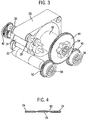
Figure 3 shows a slightly modified version of one of the banknote stores ofFigure 1 ; and -
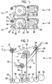
Figure 4 is a cross-sectional view of modified strips of a banknote store. - Referring to
Figure 1 , fourbanknote stores Store 10 comprises a first, or storage, winding means and two second, or supply, winding means. The first winding means may take the form of astorage drum 18 and the second winding means may take the form ofsupply drums strips rollers roller 28 to supplydrum 20, and theother strip 26 extending aroundroller 30 to supplydrum 22. Betweenroller 28 andsupply drum 20,strip 24 is guided byadditional rollers 32. The strips have marks spaced at regular intervals on one or both sides for indicating distance. The strips are one example of elongate support members but other examples may be used instead. - If the
storage drum 18 and thesupply drums strips respective supply drums storage drum 18 and thesupply drums - Banknotes (60, see
Figure 2 ) can be fed between thestrips rollers storage drum 18. Thus, individual banknotes can be stored in a spiral arrangement on the storage drum, in successive positions betweenstrips Figure 1 , an endless belt orstrip 34 and series ofrollers 36 can be used to guide the banknote from one position relative to thebanknote store 10 to be taken up betweenstrips strips rollers strips strips rollers - Referring to
Figure 2 , amotor 38 is used for driving, via agear 40, the shafts of therollers strips -
Gears Figure 1 ) ofstorage drum 18 and supplydrums lines 52 inFigure 2 . These gears interengage such that they rotate together, in this case by interengagingstorage drum gear 44 with firstsupply drum gear 46, and firstsupply drum gear 46 with secondsupply drum gear 50 via anidler gear 48. (InFigure 2 , the arrangement differs slightly fromFigure 1 , in that the supply drums rotate in the same direction, so theidler gear 48 is provided betweengears - Biasing means in the form of spiral or
torsional springs respective gears strips -
Angular rotation sensors shafts storage drum 18 and the supply drums 20, 22 respectively. Linear motion sensors in the form of sensors which sense marks on thestrips strips guide rollers 36, and associated with a sensor for sensing marks on the coding wheel. The rotation of the coding wheel can then be used to determine the linear translation of the belt. The angular rotation sensors and linear motion sensors are connected to a control device (not shown). - A practical arrangement is shown in
Figure 3 , in which like reference numbers represent like integers. The store ofFigure 3 is similar to those ofFigures 1 and 2 except for a re-arrangement of the relative positions of the drums, rollers and gears, and theangular rotation sensors linear motion sensors Fig. 2 are not shown. In this case, thegear 44 for thedrum 18 engages each of thegears - The banknote store operates as follows.
- The
rollers strips respective springs - In the preferred embodiment, the gear ratios are set so that, for each drum, when the drum is halfway between its empty and full state, the rotational speed of the driving gear matches the rotational speed of the drum, as determined by the speed of movement of the
strips - In such an arrangement, the spring for each drum has its minimum tension when the drum is half full, although this tension is still significant because the spring is pre-loaded during assembly.
- If the drum is less than half full, the periphery will be relatively small so that the drum should rotate faster than the gear. Thus, if the strip is being unwound, the speed of the strip rotates the drum relative to its associated gear, resulting in tensioning of the spring. On the other hand, if the strip is being wound on to the drum, the relatively fast feeding of the strip to the drum means that the spring is allowed to relax, causing an increased peripheral speed of the drum.
- Conversely, if the drum is more than half full, the diameter of the drum including the strip wound thereon will be relatively large, and therefore the drum should rotate relatively slowly. The tension in the strip will slow down the drum relative to the driving gear, causing the spring to become gradually tighter, if the strip is being wound on the drum. If it is being unwound, the spring is able to relax, as the drum rotates relative to its associated gear, resulting in the drum rotating slower than the gear.
- The result is that, for each drum, as the drum rotates to permit the strip to be unwound from the full state to the empty state, the tension in the spring first decreases to a minimum and then increases again. Similarly, when winding the strip on to the drum, the tension in the spring decreases to a minimum before rising again.
- This arrangement has significant benefits. First, it means that the range of tension in each spring is relatively small, thus making it easier to select a suitable spring and to manufacture the assembly, and reducing the range of tensions applied to the strips. Second, the changes in tension within the springs for the supply drums 20, 22 occur at substantially the same time as corresponding changes in tension in the spring for the
main drum 18. This balances the tension on both sides of theroller 28, thus reducing the risks of thestrips - The linear motion sensors and the angular rotation sensors are used to determine the diameter or radius of one or more of the
storage drum 18 andsupply drums - The following procedure refers to supply
drum 20, but the same procedure may be applied to any ofsupply drums - Between first and second known times, the amount of rotation of
supply drum 20 is detected byangular rotation sensor 21 and the corresponding amount of linear movement ofbelt 24 is detected bylinear motion sensor 25. The detected rotation amount θ and the linear movement amount 1 are processed in the control device. - More specifically, the corresponding diameter d of the supply drum is calculated using the equation:
- l=rθ, where 2r=d and θ is measured in radians
- In other words, d=2l/θ.
- This diameter measurement may be used as an approximation irrespective of whether the drum is winding the strips on or off the drum.
- In the case of winding the strip onto the supply drum, the diameter measurement should be a good approximation of the wound supply drum. In the case of unwinding the strip from the supply drum, it may be appropriate to subtract the thickness of the strip from the diameter measurement to get a more accurate calculation of the diameter of the supply drum after the unwinding.
- Similarly, in the case of the storage drum, the diameter measurement as calculated above should give a good approximation of the storage drum after the strips and possibly banknotes are wound on. On the other hand, the diameter calculation may take into account the thickness of the strips and possibly also banknotes wound off the storage drum for a more accurate measurement.
- In an alternative arrangement, a drum is moved by a predetermined amount and the corresponding amount of linear movement of the corresponding strip is measured. The resulting measurements for θ and 1 are then used to calculate the corresponding diameter of the drum as described above.
- For example, the
stepper motor 38 moves a drum by a predetermined amount, such as 1/12th of a full rotation, and the corresponding amount of movement of the corresponding strip is measured using the corresponding linear sensor. - Similarly, in another alternative arrangement, a strip is moved by a predetermined amount, and the corresponding amount of rotation by a drum required is measured. The resulting measurements for θ and l are then used to calculate the corresponding diameter of the drum as described above.
- For example, the tape is moved by a fixed amount, such as the fixed amount required to store a new bill on the
storage drum 18, and the amount of rotation required to achieve this is measured. - The resulting diameters derived as set out above may be used in various ways. The uses may alternatively involve other methods of measuring diameters, but the method described above is preferred.
- For example, one or more diameters may be compared with one or more thresholds. Two or more diameters may be combined, and similarly compared with one or more thresholds.
- For example, in the case of the
storage drum 18, the diameter of thedrum 18 may be compared with a threshold so that no more banknotes are stored when the diameter reaches a certain level. This can prevent jamming which might otherwise occur when the diameters becomes too large. - The minimum diameters of the drums are determined by the diameter of the respective shafts. Thus, thresholds based on the minimum diameters may be used to indicate the end of the strips.
- Especially in the case of a supply drum, the maximum diameter is determined by the length of the tape. Thus, thresholds based on the maximum diameter may also be used to indicate the end of the tape.
- This means that a separate sensor for detecting the end of the strips is not required.
- It is possible that there may be a condition in the apparatus whereby two or more drums in the apparatus may interfere with each other, for example, depending on banknote storage and banknote thickness. To avoid such a situation, it might be necessary, for example, to space the drums sufficiently far apart so that, whatever the thickness of banknotes stored on the drum and however many banknotes are stored, the drums cannot interfere with other, or, for example, to put a predetermined limit on the number of banknotes stored. As a result, the banknote store might be large or limited in the number of banknotes that can be stored. To overcome these problems, using an embodiment of the invention, a combination of diameters of two or more drums in the apparatus may be used and compared with thresholds, for example, preventing additional storage of banknotes if the combination exceeds a threshold. As a result, the drums can be placed relatively close to each other, reducing the size of the banknote store, and provide dynamic control of storage.
- Diameter measurements may be used, for example, to detect theft of banknotes from a store. In an embodiment of the invention, the diameter of the store is measured at a first time, such as when the apparatus containing the store is powered down, and then the diameter of the store is measured again when the apparatus is powered up. The two diameters are then compared, for example, by comparing the difference with a threshold. If the comparison indicates that the diameters are difference, or different by more than a given amount, then this may indicate that one or more banknotes have been removed while the apparatus was powered down. The diameter measurements may form part of the powering down/up routines, for example, by moving the strip or the drum by a corresponding amount and determining the corresponding movement of the drum or strip.
- Diameter measurements may also be used, for example, to estimate the remaining capacity of the store. This is especially useful if the store is used as an escrow (temporary store for banknotes inserted in a transaction, which may subsequently be returned to the user, or retained in a store). For example, if the current diameter of the store and the total length of the belt are known, then the approximate remaining capacity, or turns on the store, can be calculated. This can be combined with known information about approximate lengths of banknotes to estimate the remaining capacity, or the number of further banknotes that can be stored.
- In operation, the banknote store may be initialised after manufacture by running the
strips linear sensors - The above techniques may be applied to other winding means similar as storage and supply drums, and may be used in other types of banknote stores.
- The above techniques may be also be applied using angular velocity or angular acceleration sensors, and linear velocity or linear acceleration sensors etc, from which corresponding angular rotation θ and linear movement 1 can be calculated by integration. However, this is less desirable because such sensors require more space and cost more, and also addition processing is required.
- Alternatives to the above arrangement are possible. For example, the gear ratios could be selected so that the speed of rotation of the drum matches that of the associated gear when the drum is fully wound (or fully unwound), in which case the tension in the spring will monotonically change as the drum is fully unwound (or wound).
- One advantage of the above-described arrangement is that the speed of movement of the
strips rollers - Although
Figure 2 shows springs associated with thestorage drum 18 and the supply drums 20, 22, it would be possible to use springs associated with the supply drums only or the storage drum only, although in such arrangements a constant speed of movement of thestrips - Reference has been made to spiral or torsional springs but other types of biasing means could be used, as required. The purpose of the springs is to allow relative rotational movement between the drums and their respective gears or coupling means whilst biasing the drums in a direction to cause the strips to be held tightly.
- In
Figures 1 and 2 , twostrips - In a modification of the illustrated embodiment shown in
Figure 4 , strips 24, 26 do not overlap. Twostrips 24 are wound around the storage drum and a first supply drum. Theother strip 26 is wound around the storage drum and a second supply drum. When thestrips banknote 60 is supported between the strips, withstrips strip 26 on the other side thereof. This has the advantage that two windings of the modified strips have approximately the same radial thickness as a single winding ofstrips Figure 4 . With the reduced thickness, the amount of extension and retraction required to be performed by the biasing means is reduced, since the maximum change in thickness during operation of the storage drum for a given number of banknotes is less. This achieves a more compact design or alternatively means that more banknotes can be stored on a drum of the same approximate size, the governing factor being concerned more with the thickness of the banknotes and less so with the thickness of the strips. - The arrangements described above could be modified by supplying a positive driving force to the various drums, for example using a
gear 42 shown in broken lines inFigure 2 to transmit the rotation produced by themotor 38 to thegears - Instead of the gears shown schematically in
Figure 2 , other arrangements, such as belts, could be used for coupling together the shafts of the various drums. - Instead of storing the banknotes on one drum only, the arrangement could enable transferring of banknotes from one drum to another.
- In the specification, of course the radius can be used instead of the diameter, or derivations from the radius or diameter, with due alterations in detail, and the term diameter in the claims is intended to cover all such modifications.
- Although the present invention is defined in the attached claims, it is to be understood that the invention can alternatively also be defined in accordance with the following embodiments:
- 1. A method of controlling a banknote store comprising at least one winding means and at least one elongate support means which can be wound and/or unwound from the winding means for storing and/or transporting a banknote, the method comprising determining the radius or diameter of a spool comprising at least the winding means using the degree of rotation of the winding means and the corresponding linear amount of movement of the elongate support means.
- 2. The method of embodiment 1 wherein the spool comprises winding means and wound support means, to determine the combined diameter or radius of winding means and wound support means.
- 3. The method of embodiment 1 or embodiment 2 comprising determining the amount of linear movement by the support means when the winding means rotates by a predetermined amount.
- 4. The method of embodiment 3 comprising using a linear motion sensor for determining the amount of linear movement.
- 5. The method of embodiment 1 or embodiment 2 comprising determining the degree of rotation of the winding means when the support means translates by a predetermined amount.
- 6. The method of embodiment 5 comprising using an angular motion sensor to determine the angular rotation.
- 7. The method of any preceding embodiment wherein the winding means is a storage drum for storing banknotes.
- 8. The method of embodiment 7 wherein the spool further comprises banknotes stored on the storage drum, to determine the combined diameter or radius of winding means, wound support means and banknotes.
- 9. The method of any of embodiments 1 to 6 wherein the winding means is a reel for supplying and/or removing the support means.
- 10. The method of any preceding embodiment comprising using a stepper motor to rotate the winding means.
- 11. The method of any preceding embodiment comprising using indicia on the support means or a guide roller for the support means and means for sensing said indicia for determining the amount of movement of the support means.
- 12. The method of any preceding embodiment wherein the banknote store comprises first and second winding means mount for rotation about respective axes on first and second shafts, and wherein the elongate support means can be unwound from one of the winding means onto the other of the winding means, and vice versa, such that banknotes can be supported in succession by the support member while that is wound around at least one of the winding means.
- 13. The method of any preceding embodiment wherein the banknote store comprises at least first and second winding means, the method comprising determining the combined diameters/radii of the at least first and second winding means.
- 14. The method of any preceding embodiment comprising comparing the diameter/radius or combined diameters/radii with a threshold.
- 15. The method of any preceding embodiment comprising deciding on storage of further banknotes in the store depending on the determined radius/diameter or radii/diameters.
- 16. The method of any preceding embodiment comprising determining the beginning/end of the support means using the determined radius/diameter or radii/diameters.
- 17. The method of any preceding embodiment using the formula I = rθ where I is amount of linear movement, r is radius and θ is amount of angular rotation.
- 18. The method of any preceding embodiment comprising transferring said support means from first winding means to second winding means to initialize the banknote store.
- 19. A method of controlling a banknote store comprising at least one winding means and at least one elongate support means which can be would and/or unwound from the winding means for storing and/or transporting a banknote, the method comprising monitoring the radius or diameter of the spool and comparing the radius or diameter with a threshold.
- 20. The method of embodiment 19 for determining the end of support means or a preferred maximum or minimum capacity of the store.
- 21. The method of embodiment 19 or
embodiment 20 comprising controlling addition or removal of banknotes based on the determined radius or diameter. - 22. A method of monitoring a banknote store comprising at least one winding means and at least one elongate support means which can be would and/or unwound from the winding means for storing and/or transporting a banknote, the method comprising determining and comparing the diameter of the banknote store at different times.
- 23. The method of
embodiment 22 comprising determining and comparing the diameter of the banknote store when the store is powered down and powered up. - 24. The method of
embodiment 22 orembodiment 23 for determining if banknotes have been removed from the store. - 25. The method of
embodiment 24 comprising outputting a signal if one or more notes have been removed. - 26. The method of any of
embodiments 22 to 25 comprising comparing the difference between the diameters with a threshold. - 27. A method of estimating the capacity of a banknote store comprising at least one winding means and at least one elongate support means which can be would and/or unwound from the winding means for storing and/or transporting a banknote, the method comprising using radius or diameter measurements.
- 28. The method of
embodiment 27 comprising estimating the remaining capacity of a banknote store based on the radius or diameter of the store. - 29. The method of
embodiment 28 comprising determining whether to use the store as an escrow based on the remaining capacity. - 30. The method of any of embodiments 19 to 29 using the method of any of embodiments 1 to 18.
- 31. A banknote store comprising at least one winding means and at least one elongate support means which can be wound and/or unwound from the winding means for storing and/or transporting a banknote, comprising means for controlling the banknote store using the method of any preceding embodiment.
- 32. The banknote store of embodiment 31 wherein the winding means is a storage drum for storing banknotes.
- 33. The banknote store of embodiment 31 or
embodiment 32 wherein the winding means is a reel for supplying and/or removing the support means. - 34. The banknote store of any of embodiments 31-33 comprising a stepper motor to rotate the winding means.
- 35. The banknote store of any of embodiments 31-34 comprising indicia on the support means and means for sensing said indicia for determining the amount movement of the support means.
- 36. The banknote store of embodiment 35 wherein said indicia are marks.
- 37. The banknote store of any of embodiments 31-36 comprising first and second winding means mount for rotation about respective axes on first and second shafts, wherein the elongate support means can be unwound from one of the winding means onto the other of the winding means, and vice versa, such that banknotes can be supported in succession by the support member while that is wound around at least one of the winding means.
- 38. The banknote store of any of embodiments 31-37 comprising an angular motion sensor to determine the angular rotation.
- 39. The banknote store of any of embodiments 31-38 comprising a linear motion sensor for determining the amount of linear movement.
Claims (14)
- A method of monitoring a banknote store (10) comprising at least one winding means (18) and at least one elongate support means (24, 26) which can be wound and/or unwound from the winding means (18) for storing and/or transporting a banknote (60), the method comprising sensing indicia on the at least one elongate support means (24, 26) to determine an amount of movement of the at least one elongate support means (24, 26);
determining a diameter of a spool at different times;
comparing the measured diameters of the spool at different times; and determining whether banknotes have been removed from the banknote store based on the comparison. - The method of claim 1 comprising determining and comparing the diameter of the spool when the banknote store is powered down and powered up.
- The method of claim 1 or claim 2 comprising outputting a signal if one or more banknotes have been removed.
- The method of any preceding claim, comprising comparing the difference between the diameters with a threshold.
- The method of any preceding claim, wherein the winding means (18) is connected with a biasing means to keep the support means (24, 26) under tension.
- The method of claim 5, wherein the biasing means is in the form of a spiral or torsional spring (54).
- The method of claim 6 wherein a peripheral speed of the winding means (18) matches to a speed at which the support means (24, 26) is fed to or from the winding means (18) by the contraction and expansion of the spring (54).
- The method of any preceding claim, wherein the winding means (18) is a storage drum for storing banknotes.
- The method of claim 8, wherein the spool further comprises banknotes stored on the storage drum, to determine the combined diameter or radius of winding means (18), wound support means (24, 26) and banknotes.
- The method of any preceding claim, wherein the winding means (18) is a reel for supplying and/or removing the support means (24, 26).
- The method of any preceding claim comprising using a stepper motor (38) to rotate the winding means (18).
- The method of any preceding claim wherein the banknote store comprises first and second winding means (18, 20, 22) mounted for rotation about respective axes on first and second shafts, and wherein the elongate support means (24, 26) can be unwound from one of the winding means (20, 22) onto the other of the winding means (18), and vice versa, such that banknotes can be supported in succession by the support means (24, 26) while that is wound around at least one of the winding means (18).
- The method of any preceding claim comprising transferring said support means (24, 26) from first winding means (18) to second winding means (20, 22) to initialize the banknote store (10).
- A banknote store comprising at least one winding means (18) and at least one elongate support means (24, 26) which can be wound and/or unwound from the winding means for storing and/or transporting a banknote, comprising means for controlling the banknote store using the method of any preceding claim.
Priority Applications (2)
| Application Number | Priority Date | Filing Date | Title |
|---|---|---|---|
| ES14172660.4T ES2581297T3 (en) | 2005-10-06 | 2005-10-06 | Banknote storage |
| EP14172660.4A EP2803608B1 (en) | 2005-10-06 | 2005-10-06 | Banknote store |
Applications Claiming Priority (2)
| Application Number | Priority Date | Filing Date | Title |
|---|---|---|---|
| EP14172660.4A EP2803608B1 (en) | 2005-10-06 | 2005-10-06 | Banknote store |
| EP05256261.8A EP1772406B1 (en) | 2005-10-06 | 2005-10-06 | Banknote store |
Related Parent Applications (2)
| Application Number | Title | Priority Date | Filing Date |
|---|---|---|---|
| EP05256261.8A Division-Into EP1772406B1 (en) | 2005-10-06 | 2005-10-06 | Banknote store |
| EP05256261.8A Division EP1772406B1 (en) | 2005-10-06 | 2005-10-06 | Banknote store |
Publications (2)
| Publication Number | Publication Date |
|---|---|
| EP2803608A1 EP2803608A1 (en) | 2014-11-19 |
| EP2803608B1 true EP2803608B1 (en) | 2016-04-06 |
Family
ID=35445715
Family Applications (2)
| Application Number | Title | Priority Date | Filing Date |
|---|---|---|---|
| EP05256261.8A Not-in-force EP1772406B1 (en) | 2005-10-06 | 2005-10-06 | Banknote store |
| EP14172660.4A Active EP2803608B1 (en) | 2005-10-06 | 2005-10-06 | Banknote store |
Family Applications Before (1)
| Application Number | Title | Priority Date | Filing Date |
|---|---|---|---|
| EP05256261.8A Not-in-force EP1772406B1 (en) | 2005-10-06 | 2005-10-06 | Banknote store |
Country Status (3)
| Country | Link |
|---|---|
| US (1) | US7654485B2 (en) |
| EP (2) | EP1772406B1 (en) |
| ES (2) | ES2581297T3 (en) |
Families Citing this family (16)
| Publication number | Priority date | Publication date | Assignee | Title |
|---|---|---|---|---|
| DE102007022558A1 (en) * | 2007-05-14 | 2008-11-20 | Wincor Nixdorf International Gmbh | Roll storage for sheet-shaped objects |
| ES2510550T3 (en) | 2007-06-27 | 2014-10-21 | Mei, Inc. | Document Processing Device |
| CN101828204A (en) | 2007-10-17 | 2010-09-08 | 光荣株式会社 | Paper money containing/feeding device |
| JP5233247B2 (en) * | 2007-10-31 | 2013-07-10 | 沖電気工業株式会社 | Medium storage and feeding device |
| DE102008016077A1 (en) * | 2008-03-28 | 2009-10-01 | Giesecke & Devrient Gmbh | Device for storing sheet material |
| JP4811432B2 (en) * | 2008-06-24 | 2011-11-09 | 沖電気工業株式会社 | Medium storage and feeding device |
| IT1391242B1 (en) * | 2008-08-08 | 2011-12-01 | Razzaboni Cima Spa | WAREHOUSE FOR BANKNOTES |
| US8302757B1 (en) * | 2010-09-09 | 2012-11-06 | Ncr Corporation | Media recycler |
| JP5475615B2 (en) * | 2010-10-29 | 2014-04-16 | 富士通フロンテック株式会社 | Paper sheet storage and feeding device |
| DE102011053101A1 (en) * | 2011-08-30 | 2013-02-28 | Wincor Nixdorf International Gmbh | Cashbox with double roll storage |
| JP5853798B2 (en) * | 2012-03-21 | 2016-02-09 | 沖電気工業株式会社 | Media processing device |
| CN103676990B (en) * | 2013-12-30 | 2016-12-07 | 广州广电运通金融电子股份有限公司 | Paper money temporary storage module and its drum speed control method and ATM |
| CN104609245B (en) * | 2014-12-15 | 2017-01-25 | 广州广电运通金融电子股份有限公司 | Temporary paper money storage device and control method thereof |
| JP6412623B1 (en) | 2017-09-08 | 2018-10-24 | 日本金銭機械株式会社 | Paper sheet reflux device and reflux paper sheet handling device |
| JP2021051338A (en) * | 2019-09-20 | 2021-04-01 | グローリー株式会社 | Paper sheet processing apparatus and paper sheet processing method |
| EP4159654A1 (en) * | 2021-10-01 | 2023-04-05 | Glory Ltd. | Sheet processing apparatus |
Family Cites Families (16)
| Publication number | Priority date | Publication date | Assignee | Title |
|---|---|---|---|---|
| FR1109055A (en) | 1954-06-03 | 1956-01-20 | Machine for making banknotes and the like | |
| US2996264A (en) | 1959-09-25 | 1961-08-15 | Ampex | Spring torque tape transport system |
| US3252669A (en) | 1963-12-16 | 1966-05-24 | Prec Instr Company | Tape drive mechanism |
| US3528627A (en) | 1968-02-29 | 1970-09-15 | Ideal Toy Corp | Miniature tape phonograph drive system |
| DE1952732B2 (en) | 1969-10-20 | 1971-05-13 | Grundig Emv | MAGNETIC TAPE CASSETTE |
| US4145016A (en) | 1977-03-23 | 1979-03-20 | Lockheed Electronics Company, Inc. | Tensioning apparatus |
| CH673996A5 (en) | 1987-05-11 | 1990-04-30 | Autelca Ag | |
| JPH06206646A (en) | 1993-01-11 | 1994-07-26 | Mita Ind Co Ltd | Paper feeder for image forming device |
| ATE147363T1 (en) * | 1993-11-08 | 1997-01-15 | Ferag Ag | WINDING DEVICE FOR FLEXIBLE SURFACES AND METHOD FOR WINDING FLEXIBLE SURFACES |
| DE19629900A1 (en) * | 1996-07-24 | 1998-01-29 | Siemens Nixdorf Inf Syst | Roller storage arrangement |
| EP1108667A1 (en) | 1999-11-18 | 2001-06-20 | De La Rue International Limited | Method for the storage and retrieval of sheet-like objects, particularly banknotes, and apparatus for carrying out this method |
| JP3830014B2 (en) | 2000-07-27 | 2006-10-04 | シチズン時計株式会社 | Paper discharge device |
| JP3760375B2 (en) | 2000-12-22 | 2006-03-29 | 日立オムロンターミナルソリューションズ株式会社 | Banknote handling equipment |
| EP1321409B1 (en) * | 2001-12-20 | 2007-03-28 | MEI, Inc. | Banknote store |
| JP4200048B2 (en) * | 2003-06-03 | 2008-12-24 | 日立オムロンターミナルソリューションズ株式会社 | Paper sheet storage and discharge device |
| EP1739634A1 (en) * | 2005-06-29 | 2007-01-03 | MEI, Inc. | Banknote handling apparatus |
-
2005
- 2005-10-06 EP EP05256261.8A patent/EP1772406B1/en not_active Not-in-force
- 2005-10-06 EP EP14172660.4A patent/EP2803608B1/en active Active
- 2005-10-06 ES ES14172660.4T patent/ES2581297T3/en active Active
- 2005-10-06 ES ES05256261.8T patent/ES2508744T3/en active Active
-
2006
- 2006-10-05 US US11/538,999 patent/US7654485B2/en active Active
Also Published As
| Publication number | Publication date |
|---|---|
| EP1772406B1 (en) | 2014-08-27 |
| ES2581297T3 (en) | 2016-09-05 |
| US20070221776A1 (en) | 2007-09-27 |
| EP1772406A1 (en) | 2007-04-11 |
| EP2803608A1 (en) | 2014-11-19 |
| US7654485B2 (en) | 2010-02-02 |
| ES2508744T3 (en) | 2014-10-16 |
Similar Documents
| Publication | Publication Date | Title |
|---|---|---|
| EP2803608B1 (en) | Banknote store | |
| US20040173708A1 (en) | Method for controlling a storage roller and a storage roller for storing sheet-type objects | |
| US6669136B2 (en) | Paper money handling device | |
| CN101955081B (en) | Sheet paper storage and dispensing device | |
| JP5475615B2 (en) | Paper sheet storage and feeding device | |
| JPWO2009050796A1 (en) | Paper sheet storage and feeding device | |
| JP5134731B2 (en) | Paper sheet storage and feeding device | |
| JP5242681B2 (en) | Paper sheet processing apparatus and method for controlling paper sheet processing apparatus | |
| CN103617675B (en) | The method of Paper money temporary storage device and storage bank note thereof | |
| JPS5826769A (en) | Bobbin device | |
| JP2009519533A (en) | Roll storage module and operation method thereof | |
| US7014188B2 (en) | Banknote store | |
| WO2017126129A1 (en) | Paper sheet storage mechanism and control method therefor | |
| US10065823B2 (en) | Rotary storage | |
| DK157993B (en) | BAND FOLDING APPARATUS | |
| SE469559B (en) | PROCEDURE AND DEVICE FOR WINDING OF A STRING SIZE GOODS ON A FLANGE-BORED SPOIL | |
| EP1321409B1 (en) | Banknote store | |
| US6533207B2 (en) | Method and arrangement for producing a roll from printed products | |
| US20040104256A1 (en) | Devices for drawing in a web of material | |
| WO2017203715A1 (en) | Paper sheet accommodating apparatus and control method for paper sheet accommodating apparatus | |
| KR20150124632A (en) | Bill Recycle Cassette for Recycle Type ATM | |
| EP4159654A1 (en) | Sheet processing apparatus | |
| JP2615809B2 (en) | Tape winding device and winding method | |
| JP2016018417A (en) | Tape take-up type paper money reflux device and reflux type paper money processor | |
| JPH0258184B2 (en) |
Legal Events
| Date | Code | Title | Description |
|---|---|---|---|
| PUAI | Public reference made under article 153(3) epc to a published international application that has entered the european phase |
Free format text: ORIGINAL CODE: 0009012 |
|
| 17P | Request for examination filed |
Effective date: 20140617 |
|
| AC | Divisional application: reference to earlier application |
Ref document number: 1772406 Country of ref document: EP Kind code of ref document: P |
|
| AK | Designated contracting states |
Kind code of ref document: A1 Designated state(s): DE ES GB IT |
|
| 17Q | First examination report despatched |
Effective date: 20141208 |
|
| GRAP | Despatch of communication of intention to grant a patent |
Free format text: ORIGINAL CODE: EPIDOSNIGR1 |
|
| INTG | Intention to grant announced |
Effective date: 20151125 |
|
| RAP1 | Party data changed (applicant data changed or rights of an application transferred) |
Owner name: CRANE PAYMENT INNOVATIONS, INC. |
|
| GRAS | Grant fee paid |
Free format text: ORIGINAL CODE: EPIDOSNIGR3 |
|
| GRAA | (expected) grant |
Free format text: ORIGINAL CODE: 0009210 |
|
| AC | Divisional application: reference to earlier application |
Ref document number: 1772406 Country of ref document: EP Kind code of ref document: P |
|
| AK | Designated contracting states |
Kind code of ref document: B1 Designated state(s): DE ES GB IT |
|
| REG | Reference to a national code |
Ref country code: GB Ref legal event code: FG4D |
|
| REG | Reference to a national code |
Ref country code: DE Ref legal event code: R096 Ref document number: 602005048925 Country of ref document: DE |
|
| REG | Reference to a national code |
Ref country code: ES Ref legal event code: FG2A Ref document number: 2581297 Country of ref document: ES Kind code of ref document: T3 Effective date: 20160905 |
|
| REG | Reference to a national code |
Ref country code: DE Ref legal event code: R097 Ref document number: 602005048925 Country of ref document: DE |
|
| PLBE | No opposition filed within time limit |
Free format text: ORIGINAL CODE: 0009261 |
|
| STAA | Information on the status of an ep patent application or granted ep patent |
Free format text: STATUS: NO OPPOSITION FILED WITHIN TIME LIMIT |
|
| 26N | No opposition filed |
Effective date: 20170110 |
|
| PGFP | Annual fee paid to national office [announced via postgrant information from national office to epo] |
Ref country code: GB Payment date: 20220901 Year of fee payment: 18 |
|
| PGFP | Annual fee paid to national office [announced via postgrant information from national office to epo] |
Ref country code: IT Payment date: 20220913 Year of fee payment: 18 Ref country code: ES Payment date: 20221103 Year of fee payment: 18 Ref country code: DE Payment date: 20220831 Year of fee payment: 18 |
|
| REG | Reference to a national code |
Ref country code: DE Ref legal event code: R119 Ref document number: 602005048925 Country of ref document: DE |
|
| GBPC | Gb: european patent ceased through non-payment of renewal fee |
Effective date: 20231006 |
|
| PG25 | Lapsed in a contracting state [announced via postgrant information from national office to epo] |
Ref country code: GB Free format text: LAPSE BECAUSE OF NON-PAYMENT OF DUE FEES Effective date: 20231006 |
|
| PG25 | Lapsed in a contracting state [announced via postgrant information from national office to epo] |
Ref country code: GB Free format text: LAPSE BECAUSE OF NON-PAYMENT OF DUE FEES Effective date: 20231006 Ref country code: DE Free format text: LAPSE BECAUSE OF NON-PAYMENT OF DUE FEES Effective date: 20240501 |