EP2803191B1 - Method and device for coding an image block, corresponding method and decoding device - Google Patents
Method and device for coding an image block, corresponding method and decoding device Download PDFInfo
- Publication number
- EP2803191B1 EP2803191B1 EP13700112.9A EP13700112A EP2803191B1 EP 2803191 B1 EP2803191 B1 EP 2803191B1 EP 13700112 A EP13700112 A EP 13700112A EP 2803191 B1 EP2803191 B1 EP 2803191B1
- Authority
- EP
- European Patent Office
- Prior art keywords
- block
- filter
- image
- coding
- horizontal
- Prior art date
- Legal status (The legal status is an assumption and is not a legal conclusion. Google has not performed a legal analysis and makes no representation as to the accuracy of the status listed.)
- Active
Links
- 238000000034 method Methods 0.000 title claims description 46
- 238000012952 Resampling Methods 0.000 claims description 14
- 102100034033 Alpha-adducin Human genes 0.000 claims description 3
- 101000799076 Homo sapiens Alpha-adducin Proteins 0.000 claims description 3
- 101000629598 Rattus norvegicus Sterol regulatory element-binding protein 1 Proteins 0.000 claims description 3
- 238000001914 filtration Methods 0.000 claims 4
- 239000013598 vector Substances 0.000 description 11
- 230000003044 adaptive effect Effects 0.000 description 9
- 241001362574 Decodes Species 0.000 description 7
- 238000013139 quantization Methods 0.000 description 7
- 238000004364 calculation method Methods 0.000 description 5
- 230000002123 temporal effect Effects 0.000 description 3
- 208000037170 Delayed Emergence from Anesthesia Diseases 0.000 description 2
- 102100034004 Gamma-adducin Human genes 0.000 description 2
- 101000799011 Homo sapiens Gamma-adducin Proteins 0.000 description 2
- 230000006870 function Effects 0.000 description 2
- 238000005286 illumination Methods 0.000 description 2
- 230000009466 transformation Effects 0.000 description 2
- 102100024348 Beta-adducin Human genes 0.000 description 1
- 101000689619 Homo sapiens Beta-adducin Proteins 0.000 description 1
- 230000006978 adaptation Effects 0.000 description 1
- 230000000717 retained effect Effects 0.000 description 1
- 238000010187 selection method Methods 0.000 description 1
- 230000001131 transforming effect Effects 0.000 description 1
Images


Classifications
-
- H—ELECTRICITY
- H04—ELECTRIC COMMUNICATION TECHNIQUE
- H04N—PICTORIAL COMMUNICATION, e.g. TELEVISION
- H04N19/00—Methods or arrangements for coding, decoding, compressing or decompressing digital video signals
- H04N19/10—Methods or arrangements for coding, decoding, compressing or decompressing digital video signals using adaptive coding
- H04N19/169—Methods or arrangements for coding, decoding, compressing or decompressing digital video signals using adaptive coding characterised by the coding unit, i.e. the structural portion or semantic portion of the video signal being the object or the subject of the adaptive coding
- H04N19/17—Methods or arrangements for coding, decoding, compressing or decompressing digital video signals using adaptive coding characterised by the coding unit, i.e. the structural portion or semantic portion of the video signal being the object or the subject of the adaptive coding the unit being an image region, e.g. an object
- H04N19/172—Methods or arrangements for coding, decoding, compressing or decompressing digital video signals using adaptive coding characterised by the coding unit, i.e. the structural portion or semantic portion of the video signal being the object or the subject of the adaptive coding the unit being an image region, e.g. an object the region being a picture, frame or field
-
- H—ELECTRICITY
- H04—ELECTRIC COMMUNICATION TECHNIQUE
- H04N—PICTORIAL COMMUNICATION, e.g. TELEVISION
- H04N19/00—Methods or arrangements for coding, decoding, compressing or decompressing digital video signals
- H04N19/10—Methods or arrangements for coding, decoding, compressing or decompressing digital video signals using adaptive coding
- H04N19/102—Methods or arrangements for coding, decoding, compressing or decompressing digital video signals using adaptive coding characterised by the element, parameter or selection affected or controlled by the adaptive coding
- H04N19/117—Filters, e.g. for pre-processing or post-processing
-
- H—ELECTRICITY
- H04—ELECTRIC COMMUNICATION TECHNIQUE
- H04N—PICTORIAL COMMUNICATION, e.g. TELEVISION
- H04N19/00—Methods or arrangements for coding, decoding, compressing or decompressing digital video signals
- H04N19/10—Methods or arrangements for coding, decoding, compressing or decompressing digital video signals using adaptive coding
- H04N19/102—Methods or arrangements for coding, decoding, compressing or decompressing digital video signals using adaptive coding characterised by the element, parameter or selection affected or controlled by the adaptive coding
- H04N19/103—Selection of coding mode or of prediction mode
- H04N19/105—Selection of the reference unit for prediction within a chosen coding or prediction mode, e.g. adaptive choice of position and number of pixels used for prediction
-
- H—ELECTRICITY
- H04—ELECTRIC COMMUNICATION TECHNIQUE
- H04N—PICTORIAL COMMUNICATION, e.g. TELEVISION
- H04N19/00—Methods or arrangements for coding, decoding, compressing or decompressing digital video signals
- H04N19/10—Methods or arrangements for coding, decoding, compressing or decompressing digital video signals using adaptive coding
- H04N19/134—Methods or arrangements for coding, decoding, compressing or decompressing digital video signals using adaptive coding characterised by the element, parameter or criterion affecting or controlling the adaptive coding
- H04N19/146—Data rate or code amount at the encoder output
-
- H—ELECTRICITY
- H04—ELECTRIC COMMUNICATION TECHNIQUE
- H04N—PICTORIAL COMMUNICATION, e.g. TELEVISION
- H04N19/00—Methods or arrangements for coding, decoding, compressing or decompressing digital video signals
- H04N19/10—Methods or arrangements for coding, decoding, compressing or decompressing digital video signals using adaptive coding
- H04N19/169—Methods or arrangements for coding, decoding, compressing or decompressing digital video signals using adaptive coding characterised by the coding unit, i.e. the structural portion or semantic portion of the video signal being the object or the subject of the adaptive coding
- H04N19/17—Methods or arrangements for coding, decoding, compressing or decompressing digital video signals using adaptive coding characterised by the coding unit, i.e. the structural portion or semantic portion of the video signal being the object or the subject of the adaptive coding the unit being an image region, e.g. an object
- H04N19/176—Methods or arrangements for coding, decoding, compressing or decompressing digital video signals using adaptive coding characterised by the coding unit, i.e. the structural portion or semantic portion of the video signal being the object or the subject of the adaptive coding the unit being an image region, e.g. an object the region being a block, e.g. a macroblock
-
- H—ELECTRICITY
- H04—ELECTRIC COMMUNICATION TECHNIQUE
- H04N—PICTORIAL COMMUNICATION, e.g. TELEVISION
- H04N19/00—Methods or arrangements for coding, decoding, compressing or decompressing digital video signals
- H04N19/42—Methods or arrangements for coding, decoding, compressing or decompressing digital video signals characterised by implementation details or hardware specially adapted for video compression or decompression, e.g. dedicated software implementation
- H04N19/423—Methods or arrangements for coding, decoding, compressing or decompressing digital video signals characterised by implementation details or hardware specially adapted for video compression or decompression, e.g. dedicated software implementation characterised by memory arrangements
-
- H—ELECTRICITY
- H04—ELECTRIC COMMUNICATION TECHNIQUE
- H04N—PICTORIAL COMMUNICATION, e.g. TELEVISION
- H04N19/00—Methods or arrangements for coding, decoding, compressing or decompressing digital video signals
- H04N19/42—Methods or arrangements for coding, decoding, compressing or decompressing digital video signals characterised by implementation details or hardware specially adapted for video compression or decompression, e.g. dedicated software implementation
- H04N19/439—Methods or arrangements for coding, decoding, compressing or decompressing digital video signals characterised by implementation details or hardware specially adapted for video compression or decompression, e.g. dedicated software implementation using cascaded computational arrangements for performing a single operation, e.g. filtering
-
- H—ELECTRICITY
- H04—ELECTRIC COMMUNICATION TECHNIQUE
- H04N—PICTORIAL COMMUNICATION, e.g. TELEVISION
- H04N19/00—Methods or arrangements for coding, decoding, compressing or decompressing digital video signals
- H04N19/44—Decoders specially adapted therefor, e.g. video decoders which are asymmetric with respect to the encoder
-
- H—ELECTRICITY
- H04—ELECTRIC COMMUNICATION TECHNIQUE
- H04N—PICTORIAL COMMUNICATION, e.g. TELEVISION
- H04N19/00—Methods or arrangements for coding, decoding, compressing or decompressing digital video signals
- H04N19/50—Methods or arrangements for coding, decoding, compressing or decompressing digital video signals using predictive coding
- H04N19/503—Methods or arrangements for coding, decoding, compressing or decompressing digital video signals using predictive coding involving temporal prediction
- H04N19/51—Motion estimation or motion compensation
- H04N19/523—Motion estimation or motion compensation with sub-pixel accuracy
-
- H—ELECTRICITY
- H04—ELECTRIC COMMUNICATION TECHNIQUE
- H04N—PICTORIAL COMMUNICATION, e.g. TELEVISION
- H04N19/00—Methods or arrangements for coding, decoding, compressing or decompressing digital video signals
- H04N19/50—Methods or arrangements for coding, decoding, compressing or decompressing digital video signals using predictive coding
- H04N19/59—Methods or arrangements for coding, decoding, compressing or decompressing digital video signals using predictive coding involving spatial sub-sampling or interpolation, e.g. alteration of picture size or resolution
-
- H—ELECTRICITY
- H04—ELECTRIC COMMUNICATION TECHNIQUE
- H04N—PICTORIAL COMMUNICATION, e.g. TELEVISION
- H04N19/00—Methods or arrangements for coding, decoding, compressing or decompressing digital video signals
- H04N19/80—Details of filtering operations specially adapted for video compression, e.g. for pixel interpolation
- H04N19/82—Details of filtering operations specially adapted for video compression, e.g. for pixel interpolation involving filtering within a prediction loop
-
- H—ELECTRICITY
- H04—ELECTRIC COMMUNICATION TECHNIQUE
- H04N—PICTORIAL COMMUNICATION, e.g. TELEVISION
- H04N19/00—Methods or arrangements for coding, decoding, compressing or decompressing digital video signals
- H04N19/10—Methods or arrangements for coding, decoding, compressing or decompressing digital video signals using adaptive coding
- H04N19/134—Methods or arrangements for coding, decoding, compressing or decompressing digital video signals using adaptive coding characterised by the element, parameter or criterion affecting or controlling the adaptive coding
- H04N19/146—Data rate or code amount at the encoder output
- H04N19/152—Data rate or code amount at the encoder output by measuring the fullness of the transmission buffer
-
- H—ELECTRICITY
- H04—ELECTRIC COMMUNICATION TECHNIQUE
- H04N—PICTORIAL COMMUNICATION, e.g. TELEVISION
- H04N19/00—Methods or arrangements for coding, decoding, compressing or decompressing digital video signals
- H04N19/10—Methods or arrangements for coding, decoding, compressing or decompressing digital video signals using adaptive coding
- H04N19/134—Methods or arrangements for coding, decoding, compressing or decompressing digital video signals using adaptive coding characterised by the element, parameter or criterion affecting or controlling the adaptive coding
- H04N19/157—Assigned coding mode, i.e. the coding mode being predefined or preselected to be further used for selection of another element or parameter
- H04N19/159—Prediction type, e.g. intra-frame, inter-frame or bidirectional frame prediction
-
- H—ELECTRICITY
- H04—ELECTRIC COMMUNICATION TECHNIQUE
- H04N—PICTORIAL COMMUNICATION, e.g. TELEVISION
- H04N19/00—Methods or arrangements for coding, decoding, compressing or decompressing digital video signals
- H04N19/30—Methods or arrangements for coding, decoding, compressing or decompressing digital video signals using hierarchical techniques, e.g. scalability
- H04N19/33—Methods or arrangements for coding, decoding, compressing or decompressing digital video signals using hierarchical techniques, e.g. scalability in the spatial domain
Definitions
- the invention relates to the general domain of image coding.
- the invention more particularly relates to a method for reconstructing an image block from a current image and a method for coding such a block from a block of a reference image reconstructed at a different size from the size of the current image.
- the invention also relates to the corresponding decoding and coding devices.
- the coder comprises a bitrate control module able to adapt the value of the quantization step so as to obtain the best compromise between the output bitrate of the coder and the distortion of the image signal.
- the intended output bitrate or target bitrate is low, greatly increasing the quantization step is not always the best adapted solution as it generally leads to a significant increase in the distortion of the image signal.
- the decoder subsamples the decoded image before its display as shown in figure 2 .
- the coded stream comprises a field specifying the size of the original image of the coded image.
- the adaptive resolution of the size of the image requires the storage in DPB memory (Decoded Picture Buffer) of reconstructed reference images at different sizes.
- the reconstructed images used as reference images are stored in the DPB memory.
- the stored reference images are used to determine motion compensated reference blocks.
- the reference image used for the motion compensation and the current image to code or to reconstruct from this reference image can be of a different size.
- the reference image when the reference image has a size less than (respectively greater than) the size of the current image, the reference image must be upsampled (respectively subsampled) to the size of the current image before being motion compensated.
- the subsampled or upsampled version of the reference image is also stored in the DPB memory. More generally, each reference image is stored in the DPB memory with N different sizes, N being an integer representing the number of sizes allowed by the adaptive resolution method.
- the last two reconstructed images are used as reference image for the current image.
- the image 2 uses the images 0 and 1 as reference images
- the image 3 uses the images 1 and 2 as reference images, etc.
- N 2.
- the upsampled and subsampled versions of the reconstructed reference images are greyed out in figure 3 and correspond to the additional reference images stored in the DPB memory.
- the reference images not greyed out are the reconstructed reference images.
- the adaptive resolution method thus requires more memory space as several versions (reconstructed image and upsampled and/or subsampled versions) of a same reference image are stored.
- Increasing the memory size is a problem notably in the hardware implementations for which the surface of the component is notably critical.
- the invention relates to a decoding method according to claim 1.
- the invention also relates to a coding method according to claim 4.
- the invention further relates to a decoding device according to claim 7.
- the invention also relates to a coding device according to claim 9.
- the 2D interpolation filters used for the motion compensation and the 2D upsampling and subsampling filters are generally separable filters. Hence, each 2D filter is divided into a 1D vertical filter and a 1D horizontal filter, which are successively applied to the columns and lines of a pixel block or of an image. It is immaterial to apply first the horizontal filter on the lines then the vertical filter on the columns or conversely to apply first the vertical filter on the columns then the horizontal filter on the lines.
- the separable interpolation filters typically used for motion compensation are noted MCIF (Motion Compensation Interpolation Filter) and are composed of a vertical filter noted MCIF V (fraC y ) and a horizontal filter noted MCIF H (frac x ).
- frac x ,frac y represents the non-integer part of the position of the pixel to interpolate in relation to the initial grid of pixels or even the fractional part of the motion vector used for the motion compensation.
- the motion compensation of a pixel block of a reference image is thus obtained by successively applying the filters MCIF H (frac x ) and MCIF V (fraC y ).
- the black squares represent the initial grid of pixels, the other squares represent pixels interpolated by means of the filters MCIF H (frac x ) and MCIF V (frac y ).
- the pixel H2 is obtained from at least two black pixels located on the same line by applying the filter MCIF H (0.25).
- the invention relates to a method for reconstructing a current pixel block of a current image from at least one block of a reconstructed reference image at a different size from the size of the current image.
- the reconstruction method is described with reference to figure 6 .
- only the reconstructed reference images are stored in the DPB memory, i.e. the images not greyed out in figure 3 .
- no other upsampled or subsampled version is stored.
- the reference block used to reconstruct the current block is motion compensated by means of filters GF H and GF V to determine a prediction block Bp.
- the reference block is generally identified by means of a decoded motion vector MV of components (MVx, MVy).
- the horizontal filters MCIF H and SCF H are grouped into a single filter GF H applied on the lines of a pixel block.
- the vertical filters MCIF V and SCF V are grouped into a single filter GF V applied on the columns of a pixel block.
- GF H (n, ⁇ x ,frac x ) MCIF H (frac x ) o SCF H (n, ⁇ x )
- "o" is the function composition operator.
- GF H and GF V are always 1D filters.
- the filters for interpolation and resampling horizontally on the one hand and vertically on the other hand no resampled reference image, i.e. over- or subsampled, is stored in the DPB memory in addition to the reconstructed reference image.
- the operations of upsampling or subsampling of the data of the reference image and of motion compensation of a reference block are performed jointly by applying a separable interpolation filter successively on the lines and on the columns of pixels of the reference block, which filter depends on the 'n' index, i.e. on the size of the reference image and on the size of the current image.
- Two different current pixels can be associated with the same pixel (Xref, Yref) in the reference image. They are then distinguished by their phase ( ⁇ x , ⁇ y ). Thus, to predict these two different pixels from the same reference pixel (Xref, Yref) two different filters are applied to the same pixels of the reference image according to the value of the phases. In figure 8 , the pixels ⁇ a,b,c,d ⁇ are all associated with the same value (Xref,Yref). They are distinguished by their phase:
- the invention relates to a method for coding a current pixel block of a current image from at least one block of a reconstructed reference image at a different size from the size of the current image.
- the coding method is described with reference to figure 9 .
- only the reconstructed reference images are stored in the DPB memory, i.e. the images not greyed out in figure 3 .
- no other upsampled or subsampled version is stored.
- the reference block used to code the current block is motion compensated by means of filters GF H and GF V to determine a prediction block Bp.
- the reference block is generally identified by means of a motion vector MV of components (MVx, MVy).
- the MV is determined by a motion estimation method, for example of block matching type.
- the horizontal filters MCIF H and SCF H are grouped into a single filter GF H applied on the lines of a pixel block.
- the vertical filters MCIF V and SCF V are grouped into a single filter GF V applied on the columns of a pixel block.
- GF H (n, ⁇ x ,frac x ) MCIF H (frac x ) o SCF H (n, ⁇ x )
- GF V (n, ⁇ y ,frac y ) MCIF V (frac y ) o SCF V (n, ⁇ y )
- (f o h)(x) f(h(x)).
- "o" is the filter composition operator.
- GF H and GF V are always 1D filters.
- the operations of upsampling or subsampling of the data of the reference image and of motion compensation of a reference block are performed jointly by applying an interpolation filter successively separable on the lines and the columns of pixels of the reference block, which filter depends on the 'n' index, i.e. on the size of the reference image and on the size of the current image.
- MVx MVx int + frac x
- MVx int int MVx
- MVy MVy int + frac y
- MVx int + Xcur / SXcur Yref Ycur int SYref .
- the filters GF H and GF V are then successively applied as shown in figure 8 to determine the prediction block Bp.
- Two different current pixels (Xcur, Ycur) can be associated with the same pixel (Xref, Yref) in the reference image. They are then distinguished by their phase ( ⁇ x , ⁇ y ).
- phase ⁇ x , ⁇ y .
- two different filters are applied to the same pixels of the reference image according to the value of the phases.
- the pixels ⁇ a,b,c,d ⁇ are all associated with the same value (Xref,Yref). They are distinguished by their phase:
- the filters SCF H (n) and SCF V (n) are separate from ⁇ x and ⁇ y (e.g. subsampling by 2).
- This variant is applicable to the reconstruction method and to the coding method. It is described in relation to figures 10, 11 and 12 .
- Figure 10 corresponds to figure 5
- figure 11 corresponds to figure 7
- figure 12 corresponds to figure 8 .
- the values Xref(Xcur) and Yref(Ycur) are calculated in the following manner as shown in figure 10 :
- MVx MVx i + frac x
- MVx int int MVx
- MVy MVy i + frac y
- MVy int int MVy Xref
- Xcur int SXref .
- MVx int + Xcur / SXcur Yref Ycur int SYref .
- MVy int + Ycur / SYcur (Xref(Xcur), Yref(Ycur)) is the position in the reference image of the motion compensated current pixel with the integer part of MV.
- (SXref, SYref) represents the size of the reference image and (SXcur, SYcur) represents the size of the current image.
- the filters GF H and GF V are then successively applied as follows to determine the prediction block Bp.
- the binary stream is a scalable binary stream.
- the scalable binary stream comprises a base layer coding low resolution images and at least one enhancement layer coding high resolution images, i.e. the resolution of which is greater than that of the low resolution images.
- the current image is one of the high resolution images and the reference image is one of the low resolution images.
- the reconstructed low resolution images thus being used to predict the high resolution images are then stored in low resolution, i.e. in their original resolution, in the DPB memory of the enhancement layer.
- the invention further relates to a coding device ENC described with reference to figure 12 and a decoding device DECOD described with reference to figure 13 .
- the modules shown are functional units that may or may not correspond to physically distinguishable units.
- these modules or some of them can be grouped together in a single component or circuit, or constitute functions of the same software.
- some modules may be composed of separate physical entities.
- the coding device ENC receives at input images I belonging to a sequence of images. Each image is divided into blocks of pixels each of which is associated with at least one item of image data, e.g. of luminance and/or of chrominance.
- the coding device ENC notably implements a coding with temporal prediction. Only the modules of the coding device ENC relating to coding by temporal prediction or INTER coding are represented in figure 12 . Other modules not represented and known to those skilled in the art of video coders implement the INTRA coding with or without spatial prediction.
- the coding device ENC notably comprises a calculation module ADD1 capable of subtracting pixel by pixel from a current block Bc a prediction block Bp to generate a residue or residual block noted res.
- the coding device ENC further comprises an entropy coding module COD able to code the quantized data into a binary stream S. It further comprises a module ITQ carrying out the reverse operation of module TQ.
- the module ITQ carries out a reverse quantization followed by an inverse transform.
- the module ITQ is connected to a calculation module ADD2 able to add pixel by pixel the block of data from the module ITQ and the prediction block Bp to generate a block of reconstructed image data that is stored in a DPB memory.
- the module AR is able to subsample the images at the input of the coder notably with a view to improving the bitrate-distortion compromise, i.e. notably to increase the constant bitrate reconstruction quality, the bitrate being determined by a bitrate control module.
- the coding device ENC further comprises a motion estimation module ME able to estimate at least one motion vector MV between the block Bc and a reference image Ir stored in the DPB memory or between the block Bc and the version Ir' of the resampled reference image Ir at the size of the current image.
- the motion estimation is made between the current block Bc and the source image corresponding to Ir, in which case the DPB memory is not connected to the motion estimation module ME.
- the motion data are transmitted by the motion estimation module ME to a decision module DECISION able to select a coding mode for the block Bc in a predefined set of coding modes.
- the chosen coding mode is for example the one that minimises a bitrate-distortion type criterion.
- the invention is not restricted to this selection method and the mode chosen can be selected according to another criterion for example an a priori type criterion.
- the coding mode selected by the decision module DECISION as well as the motion data, for example the motion vector or vectors in the case of the temporal prediction mode or INTER mode are transmitted to a prediction module PRED, also called motion compensation module.
- the motion vector or vectors and the selected coding mode are moreover transmitted to the entropy coding module COD to be coded in the stream S. If a coding mode INTER is retained by the decision module DECISION the prediction module PRED then determines from the reference image Ir previously reconstructed and stored in the DPB memory, the prediction block Bp from the motion vector MV determined by the motion estimation module ME. The prediction module PRED is able to determine the prediction block according to step 20 of the coding method described with reference to figure 9 .
- the calculation module ADD1 is able to implement step 22 of the coding method. Step 24 of the coding method is implemented by the modules TQ and COD.
- the decoding device DECOD is described with reference to figure 13 .
- the decoding device DECOD receives at input a binary stream S representative of a sequence of images.
- the stream S is for example transmitted by a coding device ENC.
- the decoding device DECOD comprises an entropy decoding module DEC able to generate decoded data, for example coding modes and decoded data relating to the content of the images.
- the decoding device DECOD further comprises a motion data reconstruction module.
- the motion data reconstruction module is the entropic decoding module DEC that decodes a part of the stream S representative of motion vectors.
- the motion data reconstruction module is a motion estimation module.
- the decoding device DECOD further comprises a prediction module PRED identical to the prediction module PRED of the coding device 12.
- the prediction module PRED determines from a reference image Ir previously reconstructed and stored in the DPB memory, the reference block Bp from the motion vector Vp decoded for the current block Bc by the entropy decoding module DEC.
- the prediction module PRED is able to determine the prediction block according to step 10 of the reconstruction method described with reference to figure 6 .
- the calculation module ADD3 is able to implement step 14 of the reconstruction method. Step 12 of the reconstruction method is implemented by the modules DEC and ITQ.
Description
- The invention relates to the general domain of image coding.
- The invention more particularly relates to a method for reconstructing an image block from a current image and a method for coding such a block from a block of a reference image reconstructed at a different size from the size of the current image. The invention also relates to the corresponding decoding and coding devices.
- It is known to code a sequence of images to quantize with a quantization step the image data before their coding with view to reduce the output bitrate of the coder. Traditionally, the coder comprises a bitrate control module able to adapt the value of the quantization step so as to obtain the best compromise between the output bitrate of the coder and the distortion of the image signal. When the intended output bitrate or target bitrate is low, greatly increasing the quantization step is not always the best adapted solution as it generally leads to a significant increase in the distortion of the image signal.
- Hence, it is known at low bitrates to reduce the size of the image to code by subsampling before coding as illustrated in
figure 1 . In this case, the decoder subsamples the decoded image before its display as shown infigure 2 . For this purpose, the coded stream comprises a field specifying the size of the original image of the coded image. This dynamic adaptation of the size of the image is known in English terminology as adaptive resolution - An example prior art of a method for low bitrate video coding is: SANG HEON LEE ET AL: "Hybrid Resolution Switching Method for Low Bit Rate Video Coding", IMAGE PROCESSING, 2007. ICIP 2007. IEEE INTERNATIONAL CONFERENCE ON, IEEE, PI, 1 September 2007 (2007-09-01), pages VI-73, ISBN: 978-1-4244-1436-9 which considers encoding I pictures in high resolution and B and P pictures in low resolution.
- As illustrated in
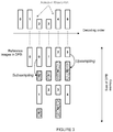
figure 3 , the adaptive resolution of the size of the image requires the storage in DPB memory (Decoded Picture Buffer) of reconstructed reference images at different sizes. Indeed, the reconstructed images used as reference images are stored in the DPB memory. In the case of the Inter coding mode, the stored reference images are used to determine motion compensated reference blocks. In the particular case of the adaptive resolution method, the reference image used for the motion compensation and the current image to code or to reconstruct from this reference image can be of a different size. Hence, when the reference image has a size less than (respectively greater than) the size of the current image, the reference image must be upsampled (respectively subsampled) to the size of the current image before being motion compensated. The subsampled or upsampled version of the reference image is also stored in the DPB memory. More generally, each reference image is stored in the DPB memory with N different sizes, N being an integer representing the number of sizes allowed by the adaptive resolution method. - In the example referred to in
figure 3 , the last two reconstructed images are used as reference image for the current image. Hence, theimage 2 uses theimages image 3 uses theimages figure 3 and correspond to the additional reference images stored in the DPB memory. The reference images not greyed out are the reconstructed reference images. - The adaptive resolution method thus requires more memory space as several versions (reconstructed image and upsampled and/or subsampled versions) of a same reference image are stored. Increasing the memory size is a problem notably in the hardware implementations for which the surface of the component is notably critical.
- The purpose of the invention is to overcome at least one of the disadvantages of the prior art. The invention is defined in the appended claims.
- For this purpose, the invention relates to a decoding method according to
claim 1. - The invention also relates to a coding method according to
claim 4. - The invention further relates to a decoding device according to claim 7.
- The invention also relates to a coding device according to claim 9.
- The invention will be better understood and illustrated by means of non-restrictiveembodiments and advantageous implementations, with reference to the accompanying drawings, wherein:
-
figure 1 illustrates a coding device with adaptive resolution according to the prior art, -
figure 2 illustrates a decoding device with adaptive resolution according to the prior art, -
figure 3 represents a sequence of 5 images to reconstruct and the change in the composition of the DPB memory of reference images when the last two reconstructed images are used as reference images, -
figure 4 illustrates the ¼ pixel interpolation of an image block, -
figure 5 illustrates a horizontal and vertical upsampling technique of an image, -
figure 6 illustrates a method for reconstructing an image block according to the invention, -
figure 7 illustrates a matching of pixels of the current image with pixels of the reference image according to the invention, -
figure 8 illustrates the motion compensation method according to the invention, -
figure 9 illustrates a method for coding an image block according to the invention, -
figure 10 illustrates a horizontal and vertical subsampling technique of an image, -
figure 11 illustrates a matching of pixels of the current image with pixels of the reference image according to an embodiment variant, -
figure 12 illustrates a coding device according to the invention, and -
figure 13 illustrates a decoding device according to the invention. - The 2D interpolation filters used for the motion compensation and the 2D upsampling and subsampling filters are generally separable filters. Hence, each 2D filter is divided into a 1D vertical filter and a 1D horizontal filter, which are successively applied to the columns and lines of a pixel block or of an image. It is immaterial to apply first the horizontal filter on the lines then the vertical filter on the columns or conversely to apply first the vertical filter on the columns then the horizontal filter on the lines. The separable interpolation filters typically used for motion compensation are noted MCIF (Motion Compensation Interpolation Filter) and are composed of a vertical filter noted MCIFV(fraCy) and a horizontal filter noted MCIFH(fracx). (fracx,fracy) represents the non-integer part of the position of the pixel to interpolate in relation to the initial grid of pixels or even the fractional part of the motion vector used for the motion compensation. For example, in the case of a ¼ pixel motion compensation, fracx∈{0 ,0.25,0.5,0.75} and fracy∈{0,0.25,0.5,0.75} as illustrated in
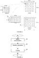
figure 4 . The motion compensation of a pixel block of a reference image is thus obtained by successively applying the filters MCIFH(fracx) and MCIFV(fraCy).
The black squares represent the initial grid of pixels, the other squares represent pixels interpolated by means of the filters MCIFH(fracx) and MCIFV(fracy). Hence, the pixel H2 is obtained from at least two black pixels located on the same line by applying the filter MCIFH(0.25). For example, the following filters can be used to interpolate with fracXorY = 0, ¼, ½, ¾: - { 0, 0, 0, 64, 0, 0, 0, 0} / 64 with fracXorY = 0,
- {-1,4, -10, 57, 19, -7, 3, -1 } / 64 with fracXorY = ¼,
- { -1, 4, -11, 40, 40, -11, 4, -1 } / 64 with fracXorY = ½,
- { -1, 3, -7, 19, 57, -10, 4, -1 } / 64 with fracXorY = ¾.
- The invention relates to a method for reconstructing a current pixel block of a current image from at least one block of a reconstructed reference image at a different size from the size of the current image. The reconstruction method is described with reference to
figure 6 . According to the invention, only the reconstructed reference images are stored in the DPB memory, i.e. the images not greyed out infigure 3 . In particular, no other upsampled or subsampled version is stored.
During astep 10, the reference block used to reconstruct the current block is motion compensated by means of filters GFH and GFV to determine a prediction block Bp. The reference block is generally identified by means of a decoded motion vector MV of components (MVx, MVy).
According to the invention, the horizontal filters MCIFH and SCFH are grouped into a single filter GFH applied on the lines of a pixel block. Likewise, the vertical filters MCIFV and SCFV are grouped into a single filter GFV applied on the columns of a pixel block.
GFH(n, θx,fracx) = MCIFH(fracx) o SCFH(n,θx)
GFV(n, θy,fracy) = MCIFV(fracy) o SCFV(n,θy)
where (f o h)(x) = f(h(x)).
"o" is the function composition operator. GFH and GFV are always 1D filters. By advantageously grouping, the filters for interpolation and resampling horizontally on the one hand and vertically on the other hand, no resampled reference image, i.e. over- or subsampled, is stored in the DPB memory in addition to the reconstructed reference image.
Hence, according to the invention the operations of upsampling or subsampling of the data of the reference image and of motion compensation of a reference block (to determine the prediction block Bp) are performed jointly by applying a separable interpolation filter successively on the lines and on the columns of pixels of the reference block, which filter depends on the 'n' index, i.e. on the size of the reference image and on the size of the current image.
For this purpose, to calculate the value of the pixels of the prediction block Bp Pred(Xcur,Ycur), the values Xref(Xcur),θx(Xcur), Yref(Ycur) and θy(Ycur) are calculated in the following manner as shown infigure 7 :


(SXref, SYref) represents the size of the reference image and (SXcur, SYcur) represents the size of the current image.
The filters GFH and GFV are then successively applied as shown infigure 8 to determine the prediction block Bp.
Two different current pixels (Xcur, Ycur) can be associated with the same pixel (Xref, Yref) in the reference image. They are then distinguished by their phase (θx, θy). Thus, to predict these two different pixels from the same reference pixel (Xref, Yref) two different filters are applied to the same pixels of the reference image according to the value of the phases.
Infigure 8 , the pixels {a,b,c,d} are all associated with the same value (Xref,Yref). They are distinguished by their phase: - θx(a) = θx(c)
- θx(b) = θx(d)
- θy(a) = θy(b)
- θy(c) = θy(d)
- u = GFH(n, θx(a),fracx)(s)
- v = GFH(n, θx(b),fracx)(s)
- pa = GFV(n, θy(a),fracy)(u)
- pb = GFV(n, θy(b),fracy)(v)
- pc = GFV(n, θy(c),fracy)(u)
- pd = GFV(n, θy(d),fracy)(v)
- GFH or V(n, θx or θy=0,fracXorY=0)={0 0 64 0 0 } / 64
- GFH or V(n, θx or θy=0.5,fracXorY=0)={-8 40 40 -8 0} / 64
- GFH or v(n, θx or θy=0,fracXorY=1/4)={0 1 5 -42 499 64 -12 -3 0 }/512
- GFH or V(n, θx or θy=0.5,fracXorY=1/4)={ 0 -4 -45 232 399 -73 2 1 0} / 512
- GFH or v(n, θx or θy=0,fracXorY=1/2)={0 1 6 -68 462 143 -28 -4 0 }/512
- GFH or v(n, θx or θy=0.5,fracXorY=1/2)={ 0 -4 -28 143 462 -68 6 1 0} / 512
- GFH or V(n, θx or θy=0,fracXorY=3/4)={0 1 2 -73 399 232 -45 -4 0} / 512
- GFH or V(n, θx or θy=0.5,fracXorY=3/4)={ 0 -3 -12 64 499 -42 5 1 0} / 512
- The invention relates to a method for coding a current pixel block of a current image from at least one block of a reconstructed reference image at a different size from the size of the current image. The coding method is described with reference to
figure 9 . According to the invention, only the reconstructed reference images are stored in the DPB memory, i.e. the images not greyed out infigure 3 . In particular, no other upsampled or subsampled version is stored.
During astep 20, the reference block used to code the current block is motion compensated by means of filters GFH and GFV to determine a prediction block Bp. The reference block is generally identified by means of a motion vector MV of components (MVx, MVy). MV is determined by a motion estimation method, for example of block matching type. According to the invention, the horizontal filters MCIFH and SCFH are grouped into a single filter GFH applied on the lines of a pixel block. Likewise, the vertical filters MCIFV and SCFV are grouped into a single filter GFV applied on the columns of a pixel block.
GFH(n, θx,fracx) = MCIFH(fracx) o SCFH(n,θx)
GFV(n, θy,fracy) = MCIFV(fracy) o SCFV(n,θy)
where (f o h)(x) = f(h(x)).
"o" is the filter composition operator. GFH and GFV are always 1D filters. By advantageously grouping, the interpolation filters and resampling horizontally on the one hand and vertically on the other hand, no resampled reference image, i.e. over- or subsampled, is stored in the DPB memory in addition to the reconstructed reference image.
Hence, according to the invention the operations of upsampling or subsampling of the data of the reference image and of motion compensation of a reference block are performed jointly by applying an interpolation filter successively separable on the lines and the columns of pixels of the reference block, which filter depends on the 'n' index, i.e. on the size of the reference image and on the size of the current image.
For this purpose, to calculate the value of the pixels of the prediction block Pred(Xcur,Ycur), the values Xref(Xcur),θx(Xcur), Yref(Ycur) and θy(Ycur) are calculated in the following manner as shown infigure 7 :


(SXref, SYref) represents the size of the reference image and (SXcur, SYcur) represents the size of the current image.
The filters GFH and GFV are then successively applied as shown infigure 8 to determine the prediction block Bp.
Two different current pixels (Xcur, Ycur) can be associated with the same pixel (Xref, Yref) in the reference image. They are then distinguished by their phase (θx, θy). Thus, to predict these two different pixels from the same reference pixel (Xref, Yref) two different filters are applied to the same pixels of the reference image according to the value of the phases.
Infigure 8 , the pixels {a,b,c,d} are all associated with the same value (Xref,Yref). They are distinguished by their phase: - θx(a) = θx(c)
- θx(b) = θx(d)
- θy(a) = θy(b)
- θy(c) = θy(d)
- u = GFH(n, θx(a),fracx)(s)
- v = GFH(n, θx(b),fracx)(s)
- s is the pixel of coordinates (Xref, Yref) in the reference image.
- pa = GFV(n, θy(a),fracy)(u)
- pb = GFV(n, θy(b),fracy)(v)
- pc = GFV(n, θy(c),fracy)(u)
- pd = GFV(n, θy(d),fracy)(v)
- According to an embodiment variant, the filters SCFH(n) and SCFV(n) are separate from θx and θy (e.g. subsampling by 2). This variant is applicable to the reconstruction method and to the coding method. It is described in relation to
figures 10, 11 and12 .Figure 10 corresponds tofigure 5 ,figure 11 corresponds tofigure 7 andfigure 12 corresponds tofigure 8 .
According to this variant, to calculate, duringsteps figure 10 :


(SXref, SYref) represents the size of the reference image and (SXcur, SYcur) represents the size of the current image.
The filters GFH and GFV are then successively applied as follows to determine the prediction block Bp.
The filters GFH are first applied as follows:
u = GFH(n, fracx)(s) The filters GFV are then applied to determine the value p of the pixels of Bp:
p = GFV(n, fracy)(u)
According to a variant, GFV is applied before GFH.
The other steps of the reconstruction and coding methods are unchanged.
According to a particular embodiment of the invention, the binary stream is a scalable binary stream. The scalable binary stream comprises a base layer coding low resolution images and at least one enhancement layer coding high resolution images, i.e. the resolution of which is greater than that of the low resolution images. The current image is one of the high resolution images and the reference image is one of the low resolution images. The reconstructed low resolution images thus being used to predict the high resolution images are then stored in low resolution, i.e. in their original resolution, in the DPB memory of the enhancement layer. - The invention further relates to a coding device ENC described with reference to
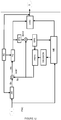
figure 12 and a decoding device DECOD described with reference tofigure 13 . In this figure, the modules shown are functional units that may or may not correspond to physically distinguishable units. For example, these modules or some of them can be grouped together in a single component or circuit, or constitute functions of the same software. On the contrary, some modules may be composed of separate physical entities. - The coding device ENC receives at input images I belonging to a sequence of images. Each image is divided into blocks of pixels each of which is associated with at least one item of image data, e.g. of luminance and/or of chrominance. The coding device ENC notably implements a coding with temporal prediction. Only the modules of the coding device ENC relating to coding by temporal prediction or INTER coding are represented in
figure 12 . Other modules not represented and known to those skilled in the art of video coders implement the INTRA coding with or without spatial prediction. The coding device ENC notably comprises a calculation module ADD1 capable of subtracting pixel by pixel from a current block Bc a prediction block Bp to generate a residue or residual block noted res. It further comprises a module TQ capable of transforming then quantizing the residual block res into quantized data. The transform T is for example a DCT. The coding device ENC further comprises an entropy coding module COD able to code the quantized data into a binary stream S. It further comprises a module ITQ carrying out the reverse operation of module TQ. The module ITQ carries out a reverse quantization followed by an inverse transform. The module ITQ is connected to a calculation module ADD2 able to add pixel by pixel the block of data from the module ITQ and the prediction block Bp to generate a block of reconstructed image data that is stored in a DPB memory. The module AR is able to subsample the images at the input of the coder notably with a view to improving the bitrate-distortion compromise, i.e. notably to increase the constant bitrate reconstruction quality, the bitrate being determined by a bitrate control module.
The coding device ENC further comprises a motion estimation module ME able to estimate at least one motion vector MV between the block Bc and a reference image Ir stored in the DPB memory or between the block Bc and the version Ir' of the resampled reference image Ir at the size of the current image. According to one variant, the motion estimation is made between the current block Bc and the source image corresponding to Ir, in which case the DPB memory is not connected to the motion estimation module ME. The motion data are transmitted by the motion estimation module ME to a decision module DECISION able to select a coding mode for the block Bc in a predefined set of coding modes. The chosen coding mode is for example the one that minimises a bitrate-distortion type criterion. However, the invention is not restricted to this selection method and the mode chosen can be selected according to another criterion for example an a priori type criterion. The coding mode selected by the decision module DECISION as well as the motion data, for example the motion vector or vectors in the case of the temporal prediction mode or INTER mode are transmitted to a prediction module PRED, also called motion compensation module. The motion vector or vectors and the selected coding mode are moreover transmitted to the entropy coding module COD to be coded in the stream S. If a coding mode INTER is retained by the decision module DECISION the prediction module PRED then determines from the reference image Ir previously reconstructed and stored in the DPB memory, the prediction block Bp from the motion vector MV determined by the motion estimation module ME. The prediction module PRED is able to determine the prediction block according to step 20 of the coding method described with reference tofigure 9 . The calculation module ADD1 is able to implementstep 22 of the coding method.Step 24 of the coding method is implemented by the modules TQ and COD. - The decoding device DECOD is described with reference to
figure 13 . The decoding device DECOD receives at input a binary stream S representative of a sequence of images. The stream S is for example transmitted by a coding device ENC. The decoding device DECOD comprises an entropy decoding module DEC able to generate decoded data, for example coding modes and decoded data relating to the content of the images. The decoding device DECOD further comprises a motion data reconstruction module. According to a first embodiment, the motion data reconstruction module is the entropic decoding module DEC that decodes a part of the stream S representative of motion vectors.
According to a variant not shown infigure 9 , the motion data reconstruction module is a motion estimation module. This solution for reconstructing motion data by the decoding device DECOD is known as "template matching".
The decoded data relating to the content of the pictures is then sent to a module ITQ capable of carrying out a reverse quantization followed by an inverse transformation. The module ITQ is identical to the module ITQ of the coding device ENC having generated the stream S. The module ITQ is connected to a calculation module ADD3 able to add pixel by pixel the block from the module ITQ and a prediction block Bp to generate a block of reconstructed image data that is stored in a DPB memory. The decoding device DECOD further comprises a prediction module PRED identical to the prediction module PRED of thecoding device 12. If a coding mode INTER is decoded, the prediction module PRED determines from a reference image Ir previously reconstructed and stored in the DPB memory, the reference block Bp from the motion vector Vp decoded for the current block Bc by the entropy decoding module DEC.
The prediction module PRED is able to determine the prediction block according to step 10 of the reconstruction method described with reference tofigure 6 . The calculation module ADD3 is able to implementstep 14 of the reconstruction method.Step 12 of the reconstruction method is implemented by the modules DEC and ITQ.
The index n corresponds to a size combination of a reference image such as reconstructed and of a current image to reconstruct. If N image sizes are authorised by the adaptive resolution method, then n ∈[0;N.(N-1)-1]. in the particular case where N=3, i.e. that 3 image sizes are authorised by the adaptive resolution method then n ∈[0;5]. Indeed, there is a filter SCFH(0,θx) to go from
The upsampling or subsampling of a reference image is thus obtained by successively applying the filters SCFH(n,θx) and SCFV(n,θy) on the lines and columns of the image.
For example, the filter {1, -3, 0, 10, 10, 0, -3, 1} / 16 is used to subsample the image data by 2. In this particular case the filter is independent from the phase. The filter {-1, 5, 5, -1} / 8 is used to subsample the image data by 2 when θx or θy=0.5 and {0, 8, 0, 0} / 8 when θx or θy=0.
In the prior art, it is thus known to apply the filters SCFH(n,θx) and SCFV(n,θy) on the reconstructed reference images with a view to generating upsampled and/or subsampled images which are stored in the DPB memory. In reference to
During a
During a
During a
Claims (10)
- A decoding method of a binary stream to reconstruct a current block of a current image from a reference block of a reference image reconstructed at a different size from the size of said current image:- motion compensating (10) said reference block of said reconstructed reference image with at least one interpolation filter composed of a horizontal motion compensation interpolation filter and a vertical motion compensation interpolation filter,- decoding (12), for the current block, a residue block, and- reconstructing (14) the current block from said residue block and from said motion compensated reference block,
said method being characterized in that a resampling is performed jointly with the motion compensating by applying a vertical filter equal to said vertical motion compensation interpolation filter composed with a vertical resampling filter and a horizontal filter equal to said horizontal motion compensation interpolation filter composed with a horizontal resampling filter. - The decoding method according to claim 1, herein the horizontal filter and the vertical filter being defined by filtering coefficients, said decoding method further comprises a decoding step of said filtering coefficients.
- The decoding method according to claim 1 or 2, wherein said binary stream is a scalable stream comprising a base layer coding low resolution images and at least one enhancement layer coding high resolution images, said current image is one of said high resolution images and said reference image is one of the low resolution images.
- A coding method of a current block of a current image from a reference block a reference image reconstructed at a different size from the size of said current image comprising:- motion compensating (20) the reference block of said reconstructed reference image with at least one interpolation filter composed of a horizontal motion compensation interpolation filter and a vertical motion compensation interpolation filter,- calculating (22), for the current block, a residue block from said current block and from said motion compensated reference block, and- coding (24) the residue block in a binary stream,
said method being characterized in that a resampling is performed jointly with the motion compensating by applying a vertical filter equal to said vertical motion compensation interpolation filter composed with a vertical resampling filter and a horizontal filter equal to said horizontal motion compensation interpolation filter composed with an horizontal resampling filter. - The coding method according to claim 4, wherein the horizontal filter and the vertical filter being defined by filtering coefficients, said coding method further comprises a coding step of said filtering coefficients.
- The coding method according to claim 4 or 5, wherein said binary stream is a scalable stream comprising a base layer coding low resolution images and at least one enhancement layer coding high resolution images, said current image is one of said high resolution images and said reference image is one of the low resolution images.
- A decoding device (DECOD) of a binary stream to reconstruct a current block of a current image from a reference block of a reference image reconstructed at a different size from the size of said current image comprising:- means for motion compensating (PRED) the reference block of the reconstructed reference image with at least one interpolation filter composed of a horizontal motion compensation interpolation filter and a vertical motion compensation interpolation filter,- means for decoding (DEC, ITQ), for the current block, a residue block, and- means for reconstructing (ADD3) the current block from said residue block and from said motion compensated reference block,
the decoding device being characterized in that a same means is configured to perform jointly a resampling and the motion compensating by applying a vertical filter equal to said vertical motion compensation interpolation filter composed with a vertical resampling filter and a horizontal filter equal to said horizontal motion compensation interpolation filter composed with an horizontal resampling filter. - The decoding device according to claim 7, said device being suitable to execute the decoding method according to one of claims 1 to 3.
- A coding device (ENC) of a current block of a current image from reference block of a reference image reconstructed at a different size from the size of said current image comprising:- means for motion compensating (PRED) the reference block of the reconstructed reference image with at least one interpolation filter composed of a horizontal motion compensation interpolation filter and a vertical motion compensation interpolation filter,- means for calculating (ADD1), for the current block, a residue block from said current block and from said motion compensated reference block, and- means for coding (TQ, COD) the residue block,
the coding device being characterized in that a same means is configured to perform jointly a resampling and the motion compensating by applying a vertical filter equal to said vertical motion compensation interpolation filter composed with a vertical resampling filter and a horizontal filter equal to said horizontal motion compensation interpolation filter composed with an horizontal resampling filter. - The coding device according to claim 9, said device being adapted to execute the coding method according to one of claims 4 to 6.
Priority Applications (1)
| Application Number | Priority Date | Filing Date | Title |
|---|---|---|---|
| EP21164841.5A EP3879829A1 (en) | 2012-01-13 | 2013-01-10 | Method and device for coding an image block, corresponding method and decoding device |
Applications Claiming Priority (2)
| Application Number | Priority Date | Filing Date | Title |
|---|---|---|---|
| FR1250334 | 2012-01-13 | ||
| PCT/EP2013/050399 WO2013104713A1 (en) | 2012-01-13 | 2013-01-10 | Method and device for coding an image block, corresponding method and decoding device |
Related Child Applications (2)
| Application Number | Title | Priority Date | Filing Date |
|---|---|---|---|
| EP21164841.5A Division EP3879829A1 (en) | 2012-01-13 | 2013-01-10 | Method and device for coding an image block, corresponding method and decoding device |
| EP21164841.5A Division-Into EP3879829A1 (en) | 2012-01-13 | 2013-01-10 | Method and device for coding an image block, corresponding method and decoding device |
Publications (2)
| Publication Number | Publication Date |
|---|---|
| EP2803191A1 EP2803191A1 (en) | 2014-11-19 |
| EP2803191B1 true EP2803191B1 (en) | 2021-05-05 |
Family
ID=47522701
Family Applications (2)
| Application Number | Title | Priority Date | Filing Date |
|---|---|---|---|
| EP13700112.9A Active EP2803191B1 (en) | 2012-01-13 | 2013-01-10 | Method and device for coding an image block, corresponding method and decoding device |
| EP21164841.5A Pending EP3879829A1 (en) | 2012-01-13 | 2013-01-10 | Method and device for coding an image block, corresponding method and decoding device |
Family Applications After (1)
| Application Number | Title | Priority Date | Filing Date |
|---|---|---|---|
| EP21164841.5A Pending EP3879829A1 (en) | 2012-01-13 | 2013-01-10 | Method and device for coding an image block, corresponding method and decoding device |
Country Status (5)
| Country | Link |
|---|---|
| US (1) | US10250877B2 (en) |
| EP (2) | EP2803191B1 (en) |
| DK (1) | DK2803191T3 (en) |
| HU (1) | HUE055104T2 (en) |
| WO (1) | WO2013104713A1 (en) |
Families Citing this family (4)
| Publication number | Priority date | Publication date | Assignee | Title |
|---|---|---|---|---|
| EP2804375A1 (en) | 2013-02-22 | 2014-11-19 | Thomson Licensing | Coding and decoding methods of a picture block, corresponding devices and data stream |
| GB2539241B (en) * | 2015-06-11 | 2019-10-23 | Advanced Risc Mach Ltd | Video processing system |
| CN111989927B (en) * | 2018-04-16 | 2023-05-09 | 联发科技股份有限公司 | Method and apparatus for video processing with overlapped block motion compensation in video codec system |
| WO2021134222A1 (en) * | 2019-12-30 | 2021-07-08 | Alibaba Group Holding Limited | Selective control of conditional filters in resolution-adaptive video coding |
Family Cites Families (7)
| Publication number | Priority date | Publication date | Assignee | Title |
|---|---|---|---|---|
| US5614952A (en) * | 1994-10-11 | 1997-03-25 | Hitachi America, Ltd. | Digital video decoder for decoding digital high definition and/or digital standard definition television signals |
| JP2000059793A (en) * | 1998-08-07 | 2000-02-25 | Sony Corp | Picture decoding device and method therefor |
| US8199812B2 (en) * | 2007-01-09 | 2012-06-12 | Qualcomm Incorporated | Adaptive upsampling for scalable video coding |
| US8638852B2 (en) * | 2008-01-08 | 2014-01-28 | Qualcomm Incorporated | Video coding of filter coefficients based on horizontal and vertical symmetry |
| US20100226437A1 (en) * | 2009-03-06 | 2010-09-09 | Sony Corporation, A Japanese Corporation | Reduced-resolution decoding of avc bit streams for transcoding or display at lower resolution |
| US9813738B2 (en) * | 2010-10-05 | 2017-11-07 | Hfi Innovation Inc. | Method and apparatus of adaptive loop filtering |
| CN103931173B (en) * | 2011-06-30 | 2016-12-21 | 维德约股份有限公司 | Motion prediction in scalable video |
-
2013
- 2013-01-10 EP EP13700112.9A patent/EP2803191B1/en active Active
- 2013-01-10 DK DK13700112.9T patent/DK2803191T3/en active
- 2013-01-10 HU HUE13700112A patent/HUE055104T2/en unknown
- 2013-01-10 US US14/372,021 patent/US10250877B2/en active Active
- 2013-01-10 WO PCT/EP2013/050399 patent/WO2013104713A1/en active Application Filing
- 2013-01-10 EP EP21164841.5A patent/EP3879829A1/en active Pending
Also Published As
| Publication number | Publication date |
|---|---|
| DK2803191T3 (en) | 2021-07-19 |
| EP3879829A1 (en) | 2021-09-15 |
| EP2803191A1 (en) | 2014-11-19 |
| US10250877B2 (en) | 2019-04-02 |
| US20150049802A1 (en) | 2015-02-19 |
| HUE055104T2 (en) | 2021-10-28 |
| WO2013104713A1 (en) | 2013-07-18 |
Similar Documents
| Publication | Publication Date | Title |
|---|---|---|
| KR101354741B1 (en) | Resampling and picture resizing operations for multi-resolution video coding and decoding | |
| EP1769633B1 (en) | Method of spatial and snr picture compression | |
| US6873655B2 (en) | Codec system and method for spatially scalable video data | |
| JP5623640B2 (en) | Video coding using high resolution reference frames | |
| JP5646641B2 (en) | Method for coding a block of an image and method for reconstructing a block of an image | |
| KR20180057676A (en) | Video motion compensation device and method with selectable interpolation filter | |
| KR101442608B1 (en) | Method and apparatus for encoding/decoding image efficiently | |
| KR101648098B1 (en) | Video encoding method and device, video decoding method and device, and program therefor | |
| JP2005507587A (en) | Spatial scalable compression | |
| JP2004312765A (en) | Effective down conversion in 2:1 decimation | |
| WO2009151563A1 (en) | Methods and apparatus for locally adaptive filtering for motion compensation interpolation and reference picture filtering | |
| KR20090080452A (en) | Apparatus and method of encoding/decoding video | |
| US20190253707A1 (en) | Video coding method and apparatus utilizing adaptive interpolation filter | |
| JP2001285867A (en) | Dct domain downward conversion system for compensating idct miss-match | |
| EP2803191B1 (en) | Method and device for coding an image block, corresponding method and decoding device | |
| US20140301488A1 (en) | Derivation of resampling filters for scalable video coding | |
| EP1743298B1 (en) | Method of down-sampling data values | |
| Liang et al. | Arbitrary downsizing video transcoding using fast motion vector reestimation | |
| KR101668133B1 (en) | Method for predicting a block of image data, decoding and coding devices implementing said method | |
| CN114009044A (en) | Simplified downsampling for matrix-based intra prediction | |
| Kim et al. | Exploiting pseudo-quadtree structure for accelerating HEVC spatial resolution downscaling transcoder | |
| JP6004852B2 (en) | Method and apparatus for encoding and reconstructing pixel blocks | |
| US20240146939A1 (en) | Derivation of resampling filters for scalable video coding | |
| JP2008512023A (en) | Method and apparatus for motion prediction | |
| WO2023205409A1 (en) | Reference picture resampling for video coding |
Legal Events
| Date | Code | Title | Description |
|---|---|---|---|
| PUAI | Public reference made under article 153(3) epc to a published international application that has entered the european phase |
Free format text: ORIGINAL CODE: 0009012 |
|
| 17P | Request for examination filed |
Effective date: 20140716 |
|
| AK | Designated contracting states |
Kind code of ref document: A1 Designated state(s): AL AT BE BG CH CY CZ DE DK EE ES FI FR GB GR HR HU IE IS IT LI LT LU LV MC MK MT NL NO PL PT RO RS SE SI SK SM TR |
|
| DAX | Request for extension of the european patent (deleted) | ||
| RAP1 | Party data changed (applicant data changed or rights of an application transferred) |
Owner name: THOMSON LICENSING DTV |
|
| STAA | Information on the status of an ep patent application or granted ep patent |
Free format text: STATUS: EXAMINATION IS IN PROGRESS |
|
| 17Q | First examination report despatched |
Effective date: 20180404 |
|
| RAP1 | Party data changed (applicant data changed or rights of an application transferred) |
Owner name: INTERDIGITAL MADISON PATENT HOLDINGS |
|
| REG | Reference to a national code |
Ref country code: DE Ref legal event code: R079 Ref document number: 602013077291 Country of ref document: DE Free format text: PREVIOUS MAIN CLASS: H04N0007260000 Ipc: H04N0019172000 |
|
| RIC1 | Information provided on ipc code assigned before grant |
Ipc: H04N 19/159 20140101ALI20200710BHEP Ipc: H04N 19/59 20140101ALI20200710BHEP Ipc: H04N 19/523 20140101ALI20200710BHEP Ipc: H04N 19/172 20140101AFI20200710BHEP Ipc: H04N 19/82 20140101ALI20200710BHEP Ipc: H04N 19/42 20140101ALI20200710BHEP Ipc: H04N 19/423 20140101ALI20200710BHEP Ipc: H04N 19/152 20140101ALI20200710BHEP |
|
| GRAP | Despatch of communication of intention to grant a patent |
Free format text: ORIGINAL CODE: EPIDOSNIGR1 |
|
| STAA | Information on the status of an ep patent application or granted ep patent |
Free format text: STATUS: GRANT OF PATENT IS INTENDED |
|
| INTG | Intention to grant announced |
Effective date: 20200826 |
|
| RIN1 | Information on inventor provided before grant (corrected) |
Inventor name: ANDRIVON, PIERRE Inventor name: SALMON, PHILIPPE Inventor name: BORDES, PHILIPPE |
|
| GRAJ | Information related to disapproval of communication of intention to grant by the applicant or resumption of examination proceedings by the epo deleted |
Free format text: ORIGINAL CODE: EPIDOSDIGR1 |
|
| STAA | Information on the status of an ep patent application or granted ep patent |
Free format text: STATUS: EXAMINATION IS IN PROGRESS |
|
| GRAP | Despatch of communication of intention to grant a patent |
Free format text: ORIGINAL CODE: EPIDOSNIGR1 |
|
| STAA | Information on the status of an ep patent application or granted ep patent |
Free format text: STATUS: GRANT OF PATENT IS INTENDED |
|
| INTC | Intention to grant announced (deleted) | ||
| INTG | Intention to grant announced |
Effective date: 20201127 |
|
| GRAS | Grant fee paid |
Free format text: ORIGINAL CODE: EPIDOSNIGR3 |
|
| GRAA | (expected) grant |
Free format text: ORIGINAL CODE: 0009210 |
|
| STAA | Information on the status of an ep patent application or granted ep patent |
Free format text: STATUS: THE PATENT HAS BEEN GRANTED |
|
| AK | Designated contracting states |
Kind code of ref document: B1 Designated state(s): AL AT BE BG CH CY CZ DE DK EE ES FI FR GB GR HR HU IE IS IT LI LT LU LV MC MK MT NL NO PL PT RO RS SE SI SK SM TR |
|
| REG | Reference to a national code |
Ref country code: GB Ref legal event code: FG4D |
|
| REG | Reference to a national code |
Ref country code: CH Ref legal event code: EP |
|
| REG | Reference to a national code |
Ref country code: AT Ref legal event code: REF Ref document number: 1391325 Country of ref document: AT Kind code of ref document: T Effective date: 20210515 |
|
| REG | Reference to a national code |
Ref country code: IE Ref legal event code: FG4D |
|
| REG | Reference to a national code |
Ref country code: DE Ref legal event code: R096 Ref document number: 602013077291 Country of ref document: DE |
|
| REG | Reference to a national code |
Ref country code: DK Ref legal event code: T3 Effective date: 20210714 |
|
| REG | Reference to a national code |
Ref country code: NL Ref legal event code: FP |
|
| REG | Reference to a national code |
Ref country code: LT Ref legal event code: MG9D |
|
| REG | Reference to a national code |
Ref country code: AT Ref legal event code: MK05 Ref document number: 1391325 Country of ref document: AT Kind code of ref document: T Effective date: 20210505 |
|
| REG | Reference to a national code |
Ref country code: HU Ref legal event code: AG4A Ref document number: E055104 Country of ref document: HU |
|
| PG25 | Lapsed in a contracting state [announced via postgrant information from national office to epo] |
Ref country code: BG Free format text: LAPSE BECAUSE OF FAILURE TO SUBMIT A TRANSLATION OF THE DESCRIPTION OR TO PAY THE FEE WITHIN THE PRESCRIBED TIME-LIMIT Effective date: 20210805 Ref country code: AT Free format text: LAPSE BECAUSE OF FAILURE TO SUBMIT A TRANSLATION OF THE DESCRIPTION OR TO PAY THE FEE WITHIN THE PRESCRIBED TIME-LIMIT Effective date: 20210505 Ref country code: HR Free format text: LAPSE BECAUSE OF FAILURE TO SUBMIT A TRANSLATION OF THE DESCRIPTION OR TO PAY THE FEE WITHIN THE PRESCRIBED TIME-LIMIT Effective date: 20210505 Ref country code: LT Free format text: LAPSE BECAUSE OF FAILURE TO SUBMIT A TRANSLATION OF THE DESCRIPTION OR TO PAY THE FEE WITHIN THE PRESCRIBED TIME-LIMIT Effective date: 20210505 Ref country code: FI Free format text: LAPSE BECAUSE OF FAILURE TO SUBMIT A TRANSLATION OF THE DESCRIPTION OR TO PAY THE FEE WITHIN THE PRESCRIBED TIME-LIMIT Effective date: 20210505 |
|
| PG25 | Lapsed in a contracting state [announced via postgrant information from national office to epo] |
Ref country code: RS Free format text: LAPSE BECAUSE OF FAILURE TO SUBMIT A TRANSLATION OF THE DESCRIPTION OR TO PAY THE FEE WITHIN THE PRESCRIBED TIME-LIMIT Effective date: 20210505 Ref country code: SE Free format text: LAPSE BECAUSE OF FAILURE TO SUBMIT A TRANSLATION OF THE DESCRIPTION OR TO PAY THE FEE WITHIN THE PRESCRIBED TIME-LIMIT Effective date: 20210505 Ref country code: LV Free format text: LAPSE BECAUSE OF FAILURE TO SUBMIT A TRANSLATION OF THE DESCRIPTION OR TO PAY THE FEE WITHIN THE PRESCRIBED TIME-LIMIT Effective date: 20210505 Ref country code: IS Free format text: LAPSE BECAUSE OF FAILURE TO SUBMIT A TRANSLATION OF THE DESCRIPTION OR TO PAY THE FEE WITHIN THE PRESCRIBED TIME-LIMIT Effective date: 20210905 Ref country code: GR Free format text: LAPSE BECAUSE OF FAILURE TO SUBMIT A TRANSLATION OF THE DESCRIPTION OR TO PAY THE FEE WITHIN THE PRESCRIBED TIME-LIMIT Effective date: 20210806 Ref country code: NO Free format text: LAPSE BECAUSE OF FAILURE TO SUBMIT A TRANSLATION OF THE DESCRIPTION OR TO PAY THE FEE WITHIN THE PRESCRIBED TIME-LIMIT Effective date: 20210805 Ref country code: PT Free format text: LAPSE BECAUSE OF FAILURE TO SUBMIT A TRANSLATION OF THE DESCRIPTION OR TO PAY THE FEE WITHIN THE PRESCRIBED TIME-LIMIT Effective date: 20210906 Ref country code: PL Free format text: LAPSE BECAUSE OF FAILURE TO SUBMIT A TRANSLATION OF THE DESCRIPTION OR TO PAY THE FEE WITHIN THE PRESCRIBED TIME-LIMIT Effective date: 20210505 Ref country code: ES Free format text: LAPSE BECAUSE OF FAILURE TO SUBMIT A TRANSLATION OF THE DESCRIPTION OR TO PAY THE FEE WITHIN THE PRESCRIBED TIME-LIMIT Effective date: 20210505 |
|
| PG25 | Lapsed in a contracting state [announced via postgrant information from national office to epo] |
Ref country code: RO Free format text: LAPSE BECAUSE OF FAILURE TO SUBMIT A TRANSLATION OF THE DESCRIPTION OR TO PAY THE FEE WITHIN THE PRESCRIBED TIME-LIMIT Effective date: 20210505 Ref country code: SK Free format text: LAPSE BECAUSE OF FAILURE TO SUBMIT A TRANSLATION OF THE DESCRIPTION OR TO PAY THE FEE WITHIN THE PRESCRIBED TIME-LIMIT Effective date: 20210505 Ref country code: SM Free format text: LAPSE BECAUSE OF FAILURE TO SUBMIT A TRANSLATION OF THE DESCRIPTION OR TO PAY THE FEE WITHIN THE PRESCRIBED TIME-LIMIT Effective date: 20210505 Ref country code: CZ Free format text: LAPSE BECAUSE OF FAILURE TO SUBMIT A TRANSLATION OF THE DESCRIPTION OR TO PAY THE FEE WITHIN THE PRESCRIBED TIME-LIMIT Effective date: 20210505 Ref country code: EE Free format text: LAPSE BECAUSE OF FAILURE TO SUBMIT A TRANSLATION OF THE DESCRIPTION OR TO PAY THE FEE WITHIN THE PRESCRIBED TIME-LIMIT Effective date: 20210505 |
|
| REG | Reference to a national code |
Ref country code: DE Ref legal event code: R097 Ref document number: 602013077291 Country of ref document: DE |
|
| PLBE | No opposition filed within time limit |
Free format text: ORIGINAL CODE: 0009261 |
|
| STAA | Information on the status of an ep patent application or granted ep patent |
Free format text: STATUS: NO OPPOSITION FILED WITHIN TIME LIMIT |
|
| 26N | No opposition filed |
Effective date: 20220208 |
|
| PG25 | Lapsed in a contracting state [announced via postgrant information from national office to epo] |
Ref country code: IS Free format text: LAPSE BECAUSE OF FAILURE TO SUBMIT A TRANSLATION OF THE DESCRIPTION OR TO PAY THE FEE WITHIN THE PRESCRIBED TIME-LIMIT Effective date: 20210905 Ref country code: AL Free format text: LAPSE BECAUSE OF FAILURE TO SUBMIT A TRANSLATION OF THE DESCRIPTION OR TO PAY THE FEE WITHIN THE PRESCRIBED TIME-LIMIT Effective date: 20210505 |
|
| PG25 | Lapsed in a contracting state [announced via postgrant information from national office to epo] |
Ref country code: MC Free format text: LAPSE BECAUSE OF FAILURE TO SUBMIT A TRANSLATION OF THE DESCRIPTION OR TO PAY THE FEE WITHIN THE PRESCRIBED TIME-LIMIT Effective date: 20210505 |
|
| REG | Reference to a national code |
Ref country code: CH Ref legal event code: PL |
|
| REG | Reference to a national code |
Ref country code: BE Ref legal event code: MM Effective date: 20220131 |
|
| PG25 | Lapsed in a contracting state [announced via postgrant information from national office to epo] |
Ref country code: LU Free format text: LAPSE BECAUSE OF NON-PAYMENT OF DUE FEES Effective date: 20220110 |
|
| PG25 | Lapsed in a contracting state [announced via postgrant information from national office to epo] |
Ref country code: BE Free format text: LAPSE BECAUSE OF NON-PAYMENT OF DUE FEES Effective date: 20220131 |
|
| PG25 | Lapsed in a contracting state [announced via postgrant information from national office to epo] |
Ref country code: LI Free format text: LAPSE BECAUSE OF NON-PAYMENT OF DUE FEES Effective date: 20220131 Ref country code: CH Free format text: LAPSE BECAUSE OF NON-PAYMENT OF DUE FEES Effective date: 20220131 |
|
| PG25 | Lapsed in a contracting state [announced via postgrant information from national office to epo] |
Ref country code: IE Free format text: LAPSE BECAUSE OF NON-PAYMENT OF DUE FEES Effective date: 20220110 |
|
| PGFP | Annual fee paid to national office [announced via postgrant information from national office to epo] |
Ref country code: FR Payment date: 20230124 Year of fee payment: 11 Ref country code: DK Payment date: 20230126 Year of fee payment: 11 |
|
| PGFP | Annual fee paid to national office [announced via postgrant information from national office to epo] |
Ref country code: IT Payment date: 20230120 Year of fee payment: 11 Ref country code: HU Payment date: 20230102 Year of fee payment: 11 Ref country code: GB Payment date: 20230124 Year of fee payment: 11 Ref country code: DE Payment date: 20230127 Year of fee payment: 11 |
|
| P01 | Opt-out of the competence of the unified patent court (upc) registered |
Effective date: 20230514 |
|
| PGFP | Annual fee paid to national office [announced via postgrant information from national office to epo] |
Ref country code: NL Payment date: 20230124 Year of fee payment: 11 |
|
| PGFP | Annual fee paid to national office [announced via postgrant information from national office to epo] |
Ref country code: NL Payment date: 20240125 Year of fee payment: 12 |