EP2802933B1 - Optical system for imaging an object - Google Patents
Optical system for imaging an object Download PDFInfo
- Publication number
- EP2802933B1 EP2802933B1 EP13700213.5A EP13700213A EP2802933B1 EP 2802933 B1 EP2802933 B1 EP 2802933B1 EP 13700213 A EP13700213 A EP 13700213A EP 2802933 B1 EP2802933 B1 EP 2802933B1
- Authority
- EP
- European Patent Office
- Prior art keywords
- unit
- image stabilization
- optical system
- image
- stabilization unit
- Prior art date
- Legal status (The legal status is an assumption and is not a legal conclusion. Google has not performed a legal analysis and makes no representation as to the accuracy of the status listed.)
- Active
Links
Images


Classifications
-
- G—PHYSICS
- G02—OPTICS
- G02B—OPTICAL ELEMENTS, SYSTEMS OR APPARATUS
- G02B27/00—Optical systems or apparatus not provided for by any of the groups G02B1/00 - G02B26/00, G02B30/00
- G02B27/64—Imaging systems using optical elements for stabilisation of the lateral and angular position of the image
- G02B27/646—Imaging systems using optical elements for stabilisation of the lateral and angular position of the image compensating for small deviations, e.g. due to vibration or shake
-
- G—PHYSICS
- G02—OPTICS
- G02B—OPTICAL ELEMENTS, SYSTEMS OR APPARATUS
- G02B23/00—Telescopes, e.g. binoculars; Periscopes; Instruments for viewing the inside of hollow bodies; Viewfinders; Optical aiming or sighting devices
- G02B23/16—Housings; Caps; Mountings; Supports, e.g. with counterweight
- G02B23/18—Housings; Caps; Mountings; Supports, e.g. with counterweight for binocular arrangements
-
- H—ELECTRICITY
- H04—ELECTRIC COMMUNICATION TECHNIQUE
- H04N—PICTORIAL COMMUNICATION, e.g. TELEVISION
- H04N23/00—Cameras or camera modules comprising electronic image sensors; Control thereof
- H04N23/60—Control of cameras or camera modules
- H04N23/68—Control of cameras or camera modules for stable pick-up of the scene, e.g. compensating for camera body vibrations
- H04N23/682—Vibration or motion blur correction
- H04N23/685—Vibration or motion blur correction performed by mechanical compensation
- H04N23/687—Vibration or motion blur correction performed by mechanical compensation by shifting the lens or sensor position
-
- G—PHYSICS
- G02—OPTICS
- G02B—OPTICAL ELEMENTS, SYSTEMS OR APPARATUS
- G02B23/00—Telescopes, e.g. binoculars; Periscopes; Instruments for viewing the inside of hollow bodies; Viewfinders; Optical aiming or sighting devices
- G02B23/02—Telescopes, e.g. binoculars; Periscopes; Instruments for viewing the inside of hollow bodies; Viewfinders; Optical aiming or sighting devices involving prisms or mirrors
Definitions
- the invention relates to an optical system for imaging an object, the optical system having a lens, an image stabilization unit and an image plane.
- the optical system is provided with an eyepiece.
- the optical system described above is used, for example, in a telescope or binoculars.
- the image captured by an observer through the telescope or binoculars is often perceived as shaky, since trembling or rotating movements of the user's hands, but also movements of the surface in turn cause movements of the optical system.
- Known solutions use stabilization devices for stabilizing the image by means of a mechanical device and / or an electronic device.
- an optical system in the form of a telescope which has a lens, an image stabilization unit in the form of a prism reversal system and an eyepiece.
- the prism reversal system is gimbal-mounted in a housing of the telescope. This is understood to mean that the prism reversal system is arranged in the housing of the telescope in such a way that the prism reversal system is rotatably mounted about two axes arranged at right angles to one another.
- a device called gimbals is generally used for the rotatable mounting.
- An articulation point of the gimbal-mounted prism reversal system is arranged centrally between a main plane of the objective on the image side and a main plane of the eyepiece on the object side.
- the gimbal-mounted prism reversal system is not moved due to its inertia due to the rotary tremor movements. It remains firmly in the room. In this way, image blurring caused by the trembling movement of the housing is compensated for.
- C2 binocular binoculars with image stabilization which have a prism reversal system.
- the prism reversal system has Porro prisms, each of which has a tilt axis.
- the Porro prisms are designed to be pivotable about their respective tilt axis. Motors are provided for pivoting the Porro prisms.
- the panning takes place in dependence on a trembling movement, which causes the observed image to wobble.
- optically neutral point is understood to be a point about which the objective and the eyepiece can be rotated relatively in space without the position of an image of an object shifting, the reversing system remaining stationary in space.
- the reversing system is arranged to be movable around the optically neutral point and around two axes which are arranged perpendicular to the optical axis.
- optically neutral point is understood to mean a point on an optical axis between a lens and an eyepiece, around which an image stabilization unit is rotatably arranged, so that in the case of a twitching motion around an arbitrary point, the direction of the image of an object, which is defined by the lens and the Eyepiece is viewed, remains stationary in the room, as is the image stabilization unit.
- a housing in which the reversing system is arranged is also quite large. It has the shape of a box. Many users describe the aesthetic impression that this brick-shaped device gives as not very beautiful.
- a relatively large reversing system means that the moment of inertia of the reversing system is quite large. Relatively large forces are therefore required to reverse the reversal system to move.
- motors with a high output are generally used, which in turn require a large installation space. Such motors also have a high energy consumption, so that this leads to shortened battery runtimes, which are generally used to supply energy to the motors.
- the invention has for its object to provide an optical system for imaging an object, which has an image stabilization unit with a relatively low moment of inertia, so that, compared to the prior art, lower forces are used to adjust the image stabilization unit and a smaller housing for the optical system can.
- the optical system according to the invention for imaging an object has a first lens, a first image stabilization unit and a first image plane. Seen from the first lens in the direction of the first image plane, first the first lens, then the first image stabilization unit and then the first image plane are arranged along a first optical axis of the optical system.
- the first objective is designed for focusing and, for example, along a first optical axis for focusing is moved.
- the first objective has at least one first front unit and at least one first focusing unit, the first focusing unit being displaced for focusing along the first optical axis.
- the focusing takes place through a first eyepiece, which is provided, for example, on the optical system and will be discussed further below.
- the first image stabilization unit has a first entry surface and a first exit surface.
- the first entrance surface is directed towards the first lens.
- the first exit surface is directed towards the first image plane.
- the first exit surface is arranged in a range of 1 mm to 20 mm at a distance from the first image plane.
- the invention is based on the surprising finding that the arrangement of the first exit surface of the first image stabilization unit relative to the first image plane in the aforementioned area makes it possible to reduce the moment of inertia of the first image stabilization unit in such a way that motors with, for example, a relatively small amount compared to the prior art Force can be used to adjust the first image stabilization unit.
- motors with, for example, a relatively small amount compared to the prior art Force can be used to adjust the first image stabilization unit.
- smaller image stabilization units than in the prior art can be used without the imaging properties of the optical system according to the invention deteriorating.
- a smaller housing than in the prior art can also be used, so that an aesthetic impression that is beautiful for many users is created.
- the optical system has one of the following features: the first exit surface is arranged in a range of 2 mm to 15 mm at a distance from the first image plane or the first exit surface is in an area 3 mm to 12 mm apart from the first image plane. Considerations have surprisingly shown that when the first exit surface is arranged in one of the aforementioned areas, the desired goal can be achieved particularly well.
- a first reticle in the first image plane, which is arranged on a first housing or on the first image capturing unit, the first reticle also carrying out any movement of the first image capturing unit.
- the aforementioned exemplary embodiments thus have the following sequence of the individual units: the first lens - the first image stabilization unit - the first image plane - the first eyepiece.
- the image plane of the first lens and the image plane of the first eyepiece coincide.
- the optical system is a first
- the first eyepiece is arranged in the first housing.
- the optical system has a second objective, a second image stabilization unit and a second image plane.
- the aforementioned units are also arranged in a specific order. It is thus provided that, viewed from the second lens in the direction of the second image plane, first the second lens, then the second image stabilization unit and then the second image plane are arranged along a second optical axis of the optical system.
- the second objective is designed for focusing and is displaced, for example, along a second optical axis for focusing.
- the focusing takes place through a second eyepiece, which is provided, for example, on the optical system and will be discussed further below.
- the second image stabilization unit now has a second entry surface and a second exit surface.
- the second entrance surface faces the second lens.
- the second exit surface faces the second image plane.
- the second exit surface is arranged at a distance of 1 mm to 20 mm from the second image plane.
- the second exit surface is arranged at a distance of 2 mm to 15 mm from the second image plane.
- the second exit surface is arranged in a range of 3 mm to 12 mm at a distance from the second image plane.
- a second reticle in the second image plane, which is arranged on a second housing or on the second image capturing unit, the second reticle also carrying out every movement of the second image capturing unit.
- the above-mentioned exemplary embodiments thus again have the following sequence of the individual units when viewed from the second lens in the direction of the second image plane: the second lens - the second image stabilization unit - the second image plane - the second eyepiece.
- the image plane of the second lens and the image plane of the second eyepiece coincide.
- the optical system has a second housing.
- the second objective, the second image stabilization unit and the second image plane are arranged in this second housing.
- the second eyepiece is also arranged, for example, in the aforementioned second housing.
- the optical system which has two housings, basically has two optical subsystems.
- a first optical subsystem is arranged in the first housing (for example, for one of the two eyes of a user).
- the first housing is connected to the second housing via at least one articulated bridge.
- the articulated bridge has a first hinge part arranged on the first housing.
- the articulated bridge has a second hinge part arranged on the second housing.
- the buckling bridge enables the adjustment of the optical system in such a way that the first housing and the second housing can be adjusted to the eye relief of a user.
- the first housing and the second housing are accordingly arranged relative to one another such that the first housing is arranged on one of the user's two eyes and that the second housing is arranged on the other of the user's two eyes. In other words, this can be expressed as follows.
- the first eyepiece has a first eyepiece axis
- the second eyepiece has a second eyepiece axis.
- a user's first eye has a first eye axis and a user's second eye has a second eye axis.
- the first housing and the second housing are accordingly arranged relative to one another in such a way that the first eyepiece axis and the first eye axis are aligned and that the second eyepiece axis and the second eye axis are aligned.
- the first image stabilization unit is designed as a first reversing system.
- the first image stabilization unit is designed as a first prism reversal system or as a first lens reversal system.
- the second image stabilization unit is designed as a second reversing system.
- the second image stabilization unit is designed as a second prism reversal system or as a second lens reversal system.
- the first image stabilization unit is arranged cardanically in the first housing.
- the first image stabilization unit is arranged in a device in such a way that the first image stabilization unit is rotatably mounted about two axes arranged at right angles to one another. For example, they do not run through a first optical neutral point on the first optical axis.
- the two axes are arranged perpendicular to the first optical axis and intersect at a first intersection.
- the first image stabilization unit is arranged in the first housing so as to be rotatable about a first axis and about a second axis, the first axis and the second axis intersecting at a first intersection.
- This intersection is different, for example, from the first optical neutral point on the first optical axis.
- the first axis and the second axis intersect the first optical axis.
- the first axis and the second axis intersect in the center of gravity of the first image stabilization unit. In this way, a very small moment of inertia of the first image stabilization unit is achieved.
- the force for adjusting the first image stabilization unit is relatively low, so that only a small amount of energy is required for the adjustment.
- the second image stabilization unit is arranged cardanically in the second housing.
- the two axes are arranged perpendicular to the second optical axis and intersect at a second intersection.
- the second image stabilization unit is arranged in the second housing so as to be rotatable about a third axis and about a fourth axis, the third axis and the fourth axis intersecting at the second intersection.
- This intersection is different, for example, from the second optical neutral point on the second optical axis.
- the third axis and the fourth axis intersect the second optical axis.
- the third axis and the fourth axis intersect in the center of gravity of the second image stabilization unit. In this way, a very small moment of inertia of the second image stabilization unit is achieved.
- the force for adjusting the second image stabilization unit is relatively small, so that only a small amount of energy is required for the adjustment.
- Such drive units have low power consumption. Furthermore, when a control voltage is switched off, such drive units have a sufficiently high holding force that a movably arranged image stabilization unit does not have to be additionally locked. It is desirable to fix a movable image stabilization unit when the optical system is not being used in order to avoid damage to the image stabilization unit and / or around the optical system (for example binoculars) even when the stabilization function is switched off continue to use as binoculars. Another advantage of such drive units is that the movement of such drive units is very precise due to the direct dependence of a control voltage supplied.
- the optical system has at least one control unit for controlling a first drive unit for moving the first image stabilization unit and a second drive unit for moving the second image stabilization unit.
- This exemplary embodiment therefore provides a single control unit for two drive units, namely for the first drive unit and for the second drive unit.
- the optical system has at least one control unit which is designed such that, for example on the basis of a coordinate transformation and / or further mathematical methods, it provides control signals which are intended for the first drive unit, can convert from a first coordinate system into control signals for the second drive unit in a second coordinate system.
- a first motion detector and a second motion detector are arranged in a first housing part.
- a third speed detector is in turn arranged in a second housing part.
- the first motion detector, the second motion detector, the third motion detector and / or the fourth motion detector are arranged only in one of the two housings.
- the first housing is designed as a tube.
- the second housing is designed as a tube.
- the optical system is designed as binoculars or as a telescope.
- An optical system for imaging an object which is not according to the invention, can have at least one of the aforementioned or following features or a combination of at least two of the aforementioned or following features.
- the not according to the invention optical system has at least one first objective, at least one first image plane, at least one second objective and at least one second image plane.
- the first objective and the first image plane are arranged in a first housing, for example a first tube.
- the second objective and the second image plane are arranged in a second housing, for example a second tube.
- at least one first image stabilization unit is arranged in the first housing and that at least one second image stabilization unit is arranged in the second housing.
- At least one first drive unit is provided for moving the first image stabilization unit.
- At least one second drive unit is provided for moving the second image stabilization unit.
- the first drive unit is arranged in the first housing and that the second drive unit is arranged in the second housing.
- the first drive unit is designed as a piezo actuator and / or, for example, the second drive unit is designed as a piezo actuator.
- the arrangement of the individual image stabilization units in each case makes it possible to significantly reduce the weight of the image stabilization units in comparison to the prior art. This makes it possible to use drive units such as piezo actuators, for example piezo bending actuators, for adjusting the image stabilization units.
- each optical system described above and below provision is additionally made to control the energy consumption of the drive units and to limit them in such a way that only the energy actually required in a given situation will be consumed.
- image stabilization is only carried out when a user actually uses the optical system. If it is recognized that a user is not using the optical system, for example binoculars, then image stabilization is not carried out.
- the scope and quality of the image stabilization are adapted to the available energy. In this exemplary embodiment, it is accordingly provided that the quality of the image stabilization is reduced if only low energy is available.
- the quality of the image stabilization is adapted to the observation situation.
- very high quality image stabilization is not absolutely necessary when using the optical system in the dark or at a very small magnification.
- image stabilization can be switched off in these two cases.
- the optical system has at least one measuring device for measuring the voltage of a voltage supply unit for supplying the first drive unit and at least one control unit, the control unit relating to at least one of the following properties is formed: limitation of an angle of rotation of the first image stabilization unit, moving the first image stabilization unit when a first limit frequency is exceeded and / or a second limit frequency is undershot, or limitation of a movement speed of the first image stabilization unit.
- the optical system has at least one measuring device for measuring the voltage of a voltage supply unit for supplying the second drive unit and at least one control unit, the control unit being designed for at least one of the following properties: limitation of one Angle of rotation of the second image stabilization unit, moving the second image stabilization unit when a first cut-off frequency is exceeded and / or falling below a second cut-off frequency, or limiting a movement speed of the second image stabilization unit.
- the voltage supply unit can only provide a small amount of energy, the maximum angle of rotation by which the first image stabilization unit and / or the second image stabilization unit is rotated is limited, for example. As a result, the movements of the two aforementioned image stabilization units become shorter and / or slower. This reduces energy consumption.
- low-frequency and / or high-frequency components of a movement of the optical system are no longer taken into account in the image stabilization.
- Low-frequency parts of a movement have hardly any effect on a detail recognizability.
- the low-frequency components are relatively large movements, so that the power consumption of the drive units is reduced if the low-frequency components are no longer taken into account in the image stabilization.
- the high-frequency components considerations have resulted in the following.
- the power required to move an image stabilization unit increases quadratically with the frequency and linearly with the amplitude of the movement.
- the amplitude of a rotary tremor motion decreases linearly with frequency. Accordingly, the power consumption of the drive units increases linearly with the frequency of the rotary tremor movement.
- the high-frequency components therefore result in high energy consumption in image stabilization. Accordingly, if these high-frequency components are dispensed with, the energy consumption drops.
- the amplitude of a movement of one of the image stabilization units is generally reduced if the voltage supply unit can only provide a certain amount of energy.
- the speed at which at least one of the image stabilization units is moved is limited to a maximum speed. This reduces the power consumption of the drive unit of the respective image stabilization unit.
- the optical system has at least one of the features which are explained below.
- the optical system has at least one brightness sensor for determining the ambient brightness and at least one system control unit.
- the system control unit switches, for example, to a night mode (image stabilization with low quality) or switches the image stabilization off completely.
- the optical system is additionally provided with at least one position sensor for determining an inclination of the optical system and with at least one system control unit for switching off image stabilization in the optical system.
- This embodiment is based on the idea that observations of an object using the optical system generally take place in such a way that the optical system is oriented almost horizontally. A deviation of the optical axis (s) of the optical system from the horizontal occurs, for example, when the optical system is worn with a band around a user's neck. If the optical axis of the optical system is oriented at an angle of, for example, 70 ° to 100 ° to the horizontal, it can be assumed that the optical system is not being used. For example, the system control unit then switches off the image stabilization.
- the optical system has at least one sensor for detecting a monocular application of the optical system and at least one system control unit for switching off image stabilization in the optical system.
- This exemplary embodiment is based on the idea that a binocular optical system can also be used monocularly. For example, this is done by arranging a so-called optics booster on one of the two optical subsystems. Under An optical booster is understood in particular to be a small telescope with a small magnification (for example 2x to 4x) that can be placed on an eyepiece and can also be used independently. This is recognized by means of the sensor (for example a switch). The system control unit then switches off the image stabilization of the other of the two optical subsystems. This saves energy.
- At least one sensor for detecting an eye of a user and at least one system control unit for switching off image stabilization in the optical system are provided. If there is no eye on the optical system, then it is not absolutely necessary to carry out image stabilization.
- a sensor for example, is suitable as a sensor for measuring the light at the eyepiece.
- Still further exemplary embodiments provide for a capacitance measurement.
- the optical system has at least one sensor for detecting an arrangement of a lens protective cap and / or eyepiece protective cap and at least one system control unit for switching off image stabilization in the optical system. If a protective cap is arranged on the lens and / or the eyepiece, it can be assumed that the optical system is not being used. The system control unit then switches off the image stabilization.
- the optical system has at least one sensor for recognizing an arrangement of a hand of a user and at least one system control unit for switching off image stabilization in the optical system. If it is recognized that no hand is touching the optical system, then it can be assumed that the optical system is not being used. The system control unit then switches off the image stabilization.
- a capacitive sensor capacitive measurement
- a photo sensor photo sensor
- a pressure sensor is used, for example.
- the optical system has at least one sensor for detecting a minimum articulation angle of the articulation bridge and at least one system control unit for switching off image stabilization in the optical system.
- This embodiment is based on the idea that, in a binocular optical system (for example binoculars), the minimum kink angle is set when the binoculars are being transported. In this case, the system control unit then switches off the image stabilization.
- the image stabilization by the first image stabilization unit and / or the second image stabilization unit is switched on as standard.
- the optical system has a switching unit (for example a push button) in order to switch the image stabilization on or off.
- the switching unit must be operated for as long as image stabilization is desired.
- binocular binoculars 1 hereinafter only called binoculars
- Figure 1A shows a first schematic representation of the binoculars 1, which has a tubular first housing part 2 and a tubular second housing part 3.
- a first optical axis 10 runs through the first housing part 2.
- a second optical axis 11 runs through the second housing part 3.
- the first housing part 2 is connected to the second housing part 3 via an articulated bridge 4.
- the articulated bridge 4 has a first hinge part 5, which is molded onto the first housing part 2.
- the articulated bridge 4 has a second hinge part 6, which is arranged on the second housing part 3.
- the first hinge part 5 has a first receiving part 7 and a second receiving part 8, between which a third receiving part 9 of the second hinge part 6 is arranged.
- An axle bolt (not shown) runs through the first receiving part 7, the second receiving part 8 and the third receiving part 9, so that the relative position of the first housing part 2 and the second housing part 3 about an articulation axis 74 can be adjusted to one another.
- the first housing part 2 and the second housing part 3 it is possible to adjust the first housing part 2 and the second housing part 3 to the pupil distance of a user, so that on the one hand the first housing part 2 is arranged on one of the two eyes of the user and so that on the other hand the second housing part 3 the other of the user's two eyes is arranged.
- FIG. 1B shows a further illustration of the binoculars 1.
- the first housing part 2 has a first optical subsystem 12.
- the first optical subsystem 12 is provided with a first objective 14A, a first image stabilization unit 16A designed as a first prism system and a first eyepiece 17A.
- a first eye 15A of a user for observing an object O can be arranged on the first eyepiece 17A.
- the first optical axis 10 of the first optical subsystem 12 is laterally offset somewhat due to the first prism system 16A (first image stabilization unit 16A), so that the first optical axis 10 is stepped.
- the first lens 14A consists of a first front unit 51A and a first focusing unit 52A. Further embodiments of the first lens 14A provide a different number of individual lenses or cemented elements consisting of lenses. For the purpose of focusing the object O viewed through binoculars 1, either the first eyepiece 17A or the first focusing unit 52A can be displaced axially along the first optical axis 10. In a further embodiment, the first front unit 51A or even the entire first objective 14A is displaced along the first optical axis 10. In another embodiment the first front unit 51A and the first focusing unit 52A are shifted relative to each other.
- the second housing part 3 has a second optical subsystem 13.
- the second optical subsystem 13 is provided with a second objective 14B, with a second image stabilization unit 16B designed as a prism system and with a second eyepiece 17B.
- a second eye 15B of the user for observing the object O can be arranged on the second eyepiece 17B.
- the second optical axis 11 of the second optical subsystem 13 is laterally offset somewhat due to the second image stabilization unit 16B (prism system), so that the second optical axis 11 is formed in stages.
- the second lens 14B consists of a second front unit 51B and a second focusing unit 52B.
- Further embodiments of the second objective 14B provide a different number of individual lenses or cemented elements consisting of lenses.
- either the second eyepiece 17B or the second focusing unit 52B can be displaced axially along the second optical axis 11.
- the second front unit 51B or even the entire second objective 14B is displaced along the second optical axis 11.
- the second front unit 51B and the second focusing unit 52B are shifted relative to one another.
- the beam direction of the light rays incident in the optical subsystems 12, 13 is as follows: Object O - objective 14A, 14B - image stabilization unit (prism system) 16A, 16B - eyepiece 17A, 17B - eye 15A, 15B .
- a rotary knob 53 is arranged on the articulated bridge 4, with which the first focusing unit 52A and the second focusing unit 52B can be moved together along the two optical axes 10 and 11.
- the first lens 14A and the second lens 14B (or to adjust at least units of the first lens 14A and the second lens 14B) relative to one another.
- both the first lens 14A and the second lens 14B produce a real image that is upside down relative to the object O in question in an image plane assigned to the respective lens 14A, 14B.
- the first prism system 16A assigned to the first lens 14A (first image stabilization unit) and the second prism system 16B assigned to the second lens 14B (second image stabilization unit) are used for image erection.
- the upside-down image is thus erected again and imaged in a new image plane, the left intermediate image plane 23A or the right intermediate image plane 23B.
- the first prism system 16A (first image stabilization unit) and the second prism system 16B (second image stabilization unit) can be constructed as an Abbe-König prism system, Schmidt-Pechan prism system, Uppendahl prism system, Porro prism system or another prism system variant.
- a first field diaphragm is sharply delimiting the field of view.
- a second field diaphragm sharply delimiting the field of view can be arranged, for example, in the right intermediate image plane 23B.
- the first eyepiece 17A is used to image the left intermediate image plane 23A at any distance, e.g. to infinity or another distance. Furthermore, the second eyepiece 17B is used to extend the image of the right intermediate image plane 23B at an arbitrary distance, e.g. to infinity or another distance.
- the first aperture diaphragm 54A of the first optical subsystem 12 and the second aperture diaphragm 54B of the second optical subsystem 13 can either be made by mounting an optical element of the corresponding optical subsystem 12, 13, usually by mounting the lenses of the first front unit 51A or the second Front unit 51B, or be formed by a separate panel. It can be imaged in the beam direction by the corresponding optical subsystem 12 or 13 in a plane that lies behind the corresponding eyepiece 17A or 17B in the beam direction and is typically 5 to 25 mm away from it. This level is called the exit pupil level.
- an extendable, rotatable or foldable first eyecup 55A can be provided on the first eyepiece 17A and an extendable, rotatable or foldable second eyecup 55B can be provided on the second eyepiece 17B.
- Figure 2A shows a schematic representation of the first optical subsystem 12, which is arranged in the first housing part 2.
- the second optical subsystem 13 arranged in the second housing part 3 has an identical structure to the first optical subsystem 12.
- the following explanations with regard to the first optical subsystem 12 thus also apply to the second optical subsystem 13.
- the first objective 14A, the first image stabilization unit 16A and the first eyepiece 17A are arranged along the first optical axis 10 from the object O in the direction of the user's first eye 15A.
- the first image stabilization unit 16A is designed as a prism reversal system.
- the first image stabilization unit 16A is designed as a lens inversion system.
- the second optical subsystem 13 has an identical structure to the first optical subsystem 12.
- the second prism system is designed as a second image stabilization unit 16B.
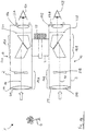
- Figure 2B shows a further schematic representation of the binoculars 1.
- Figure 2B is based on the Figure 1B .
- the same components are provided with the same reference symbols.
- Figure 2B now also shows the movement devices for the first image stabilization unit 16A and the second image stabilization unit 16B.
- the first image stabilization unit 16A is arranged in a first gimbal 60A.
- the second image stabilization unit 16B is arranged in a second cardanic mechanism 60B.
- the arrangement of the two image stabilization units 16A and 16B is shown in FIG Figure 2C presented in more detail.
- the first cardan mechanism 60A has a first outer suspension 61A, which is arranged on the first housing part 2 via a first axis 18A.
- the first outer suspension 61A is rotatable about the first axis 18A arranged.
- the first cardan mechanism 60A has a first inner suspension 62A, which is rotatably arranged on the first outer suspension 61A via a second axis 19A.
- the first inner suspension 62A is rotated about the second axis 19A via a first drive unit 24A.
- a second drive unit 24B is provided, by means of which the first outer suspension 61A is rotated about the first axis 18A.
- Figure 2E shows the above in an enlarged view.
- the first image stabilization unit 16A is held on the first inner suspension 62A by means of clamp holders 71.
- the second image stabilization unit 16B is arranged on the second cardanic mechanism 60B.
- the second gimbal 60B has a second outer suspension 61B, which is arranged on the second housing part 3 via a third axis 18B.
- the second outer suspension 61B is rotatably arranged about the third axis 18B.
- the second gimbal 60B has a second inner suspension 62B, which is rotatably arranged on the second outer suspension 61B via a fourth axis 19B.
- the second inner suspension 62B is rotated about the third axis 19B via a third drive unit 24C.
- a fourth drive unit 24D is also provided, by means of which the second outer suspension 61B is rotated about the third axis 18B.
- the first image stabilization unit 16A is arranged by means of the first cardan mechanism 60A in such a way that it is rotatably mounted about two axes arranged at right angles to one another, namely about the first axis 18A and about the second axis 19A, which projects into the sheet plane.
- the first axis 18A and the second axis 19A intersect at a first intersection 20A.
- the first intersection 20A is arranged differently from a first optically neutral point on the first optical axis 10. In this regard, reference is made to the statements already made above.
- the first image stabilization unit 16A has a first entry surface 21 and a first exit surface 22.
- the first exit surface 22 is arranged in a range of 1 mm to 20 mm at a distance from the left intermediate image plane 23A.
- the first exit surface 22 is arranged in a range of 2 mm to 15 mm at a distance from the left intermediate image plane 23A.
- the first exit surface 22 is arranged at a distance of 3 mm to 12 mm from the left intermediate image plane 23A.
- the quality of the image which is generated by the first optical subsystem 12 is improved because of manufacturing tolerances which occur during the production of the first image stabilization unit 16A have to be accepted, no longer have a strong impact on the generated image.
- the extent and volume of the first image stabilization unit 16A can be smaller compared to the prior art due to the beam path. This means that the mass of the first image stabilization unit 16A can be less than in the prior art.
- the moment of inertia of the first image stabilization unit 16A is reduced in such a way that the adjustment of the first image stabilization unit 16A can be effected with a relatively small force.
- the smaller volume, the smaller expansion and the possibility of using drive units which provide a low force for adjusting the first image stabilization unit 16A enable the first housing part 2 to be made smaller than the housing parts used in the prior art. This provides a shapely housing which reminds the user of normal binoculars and which gives an aesthetically more attractive impression than the known prior art. This creates a beautiful aesthetic impression for many users.
- the binoculars 1 in two tubes (namely a first tube corresponding to the first housing part 2 and a second tube corresponding to the second housing part 3), which corresponds to the division of a pair of binoculars which is customary for a user and what is essential for the adjustment of the eye relief simplified.
- the use of two image stabilization units namely the first image stabilization unit 16A in the first housing part 2 and the second image stabilization unit 16B in the second housing part 3) enables a significant reduction in the moment of inertia compared to the prior art of the two image stabilization units so that piezo actuators can be used.
- FIGS. 3A - 3C show schematic representations of a drive unit 24 in the form of a piezo bending actuator, an actuator being understood to be an actuating element which can generate a force or a movement. In the literature, such an actuator is often referred to as an actuator.
- the first drive unit 24A, the second drive unit 24B, the third drive unit 24C and the fourth drive unit 24D are constructed identically to the drive unit 24, for example.
- the Figure 3A shows a schematic representation of the drive unit 24.
- the drive unit 24 has a first piezoceramic 25 and a second piezoceramic 26 which are arranged one on top of the other. Both the first piezoceramic 25 and the second piezoceramic 26 can be supplied with a voltage via a voltage unit 27. In other words, a first voltage is applied to the first piezoceramic 25 and a second voltage is applied to the second piezoceramic 26.
- the two aforementioned voltages on the first piezoceramic 25 and on the second piezoceramic 26 are switched with opposite poles, so that, for example, the first piezoceramic 25 expands and, on the other hand, the second piezoceramic 26 contracts.
- the overall arrangement of the first piezoceramic 25 and the second piezoceramic 26 bends, as in FIGS Figures 3B and 3C shown.
- FIGS. 4A - 4F show schematic representations of arrangements of the drive unit 24 according to the Figures 3A - 3C on the first image stabilization unit 16A or the second image stabilization unit 16B.
- the drive unit 24 (ie the piezo bending actuator) has an arrangement formed from the first piezoceramic and the second piezoceramic.
- This arrangement has a first end and a second end.
- the first end of the arrangement is on the first housing part 2 or on the second housing part 3 fixedly arranged by means of a socket 28.
- the second end of the arrangement is connected by means of a floating bearing 29 to the first gimbal 60A of the first image stabilization unit 16A or to the second gimbal 60B of the second image stabilization unit 16B. More specifically, the second end of the assembly is movably located at a point of the first outer suspension 61A or the second outer suspension 61B.
- the point is not only to be understood in the mathematical sense, but can also be a surface or a volume.
- the point forms a lever arm 30 with the intended axis of rotation (for example, the first axis or the second axis).
- the arrangement has a longitudinal axis 31 which is arranged parallel to the first optical axis 10 or to the second optical axis 11.
- the invention is not restricted to the exemplary embodiment of an arrangement of the drive unit 24 described here. Rather, any suitable arrangement of the drive unit 24 on the first gimbal 60A of the first image stabilization unit 16A or the second gimbal 60B of the second image stabilization unit 16B can be used, in particular in the form of the exemplary embodiments described in more detail below.
- One of these exemplary embodiments includes, in particular, that it can alternatively be provided that the drive unit 24 with one of the ends of the arrangement is firmly attached to the first gimbal 60A of the first image stabilization unit 16A or to the second gimbal 60B of the second image stabilization unit 16B and with the other of the ends of the Arrangement is arranged loosely on the first housing part 2 or on the second housing part 3.
- the floating bearing 29 is designed in such a way that the drive unit 24 can move in a first direction (arrow direction A) or in a second direction (arrow direction B).
- the end of the arrangement of the drive unit 24 arranged on the floating bearing 29 should be designed in such a way that the drive unit 24 has as little play as possible on the first cardanic 60A of the first image stabilization unit 16A or the second cardanic 60B of the second image stabilization unit 16B. In this way, a particularly precise control of the movement of the first image stabilization unit 16A or the second image stabilization unit 16B is possible.
- the embodiment according to the Figure 4B is based on the exemplary embodiment according to FIG Figure 4A .
- the same components are therefore with the same reference numerals Mistake.
- the embodiment according to the Figure 4B differs from the embodiment of the Figure 4A only in that the longitudinal axis 31 of the drive unit 24 is arranged perpendicular to the first optical axis 10 or the second optical axis 11.
- the embodiment according to the Figure 4C is based on the embodiment of Figure 4A .
- the same components are therefore provided with the same reference numerals.
- the embodiment of Figure 4A shows the embodiment of Figure 4C the difference that the longitudinal axis 31 of the drive unit 24 runs along the first optical axis 10 or the second optical axis 11.
- the further embodiment according to the Figure 4D is based on the embodiment of Figure 4C .
- the same components are therefore provided with the same reference numerals.
- the embodiment of the Figure 4D differs from the embodiment of Figure 4C only in that the drive unit 24 is arranged laterally between the first housing part 2 and the first outer suspension 61A on the first image stabilization unit 16A or between the second housing part 3 and the second outer suspension 61B on the second image stabilization unit 16B such that the first image stabilization unit 16A or the second image stabilization unit 16B covers the drive unit 24.
- FIG Figure 4E A further exemplary embodiment of a possible fastening of the drive unit 24 to the first image stabilization unit 16A or the second image stabilization unit 16B is shown in FIG Figure 4E shown.
- the embodiment according to the Figure 4E is based on the exemplary embodiment according to FIG Figure 4A .
- the same components are therefore provided with the same reference numerals.
- the embodiment according to the Figure 4E differs from the embodiment of the Figure 4A a drive unit 24, the longitudinal axis 31 of which is arranged on the one hand parallel to the second axis 19A or to the fourth axis 19B, which is also the axis of rotation.
- the longitudinal axis 31 is arranged perpendicular to the first optical axis 10 or to the second optical axis 11.
- FIG. 4F Another embodiment shows the Figure 4F .
- the embodiment of the Figure 4F is also based on the embodiment of Figure 4A . Same Components are therefore provided with the same reference symbols.
- Another end of the drive unit 24 is arranged in a floating bearing 29, which is arranged on the first housing part 2 or the second housing part 3.
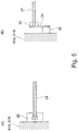
- FIGS. 5A and 5B show schematic representations of arrangements of the drive unit 24 on the first image stabilization unit 16A or on the second image stabilization unit 16B. So shows Figure 5A That the first end of the drive unit is arranged in the movable bearing 29 24, which is formed C-shaped and has the arrangement of the two above-mentioned piezoelectric ceramics.
- the floating bearing 29 is arranged on the first outer suspension 61A of the image stabilization unit 16A or on the second outer suspension 61B of the second image stabilization unit 16B.
- the Figure 5B shows the first outer suspension 61A of the first image stabilization unit 16A or the second outer suspension 61B of the second image stabilization unit 16B, on which a nozzle 35 is arranged.
- a spring plate 34 on which a clamping unit 33 is fastened, is in turn arranged on the connecting piece 35.
- the first end of the drive unit 24 is fixedly arranged on the clamping unit 33.
- the drive unit 24 assumes a specific position in space and no longer moves.
- this particular position is the position in which correct binocular adjustment is guaranteed.
- the drive unit 24 can therefore be used as a holding device which holds the first gimbals 60A of the first image stabilization unit 16A or the second gimbals 60B of the second image stabilization unit 16B.
- the first image stabilization unit 16A or the second image stabilization unit 16B can therefore no longer move in space.
- the first image stabilization unit 16A and / or the second Image stabilization unit 16B is / are locked and therefore cannot be damaged if the binoculars 1 are not used.
- the invention is not restricted to the described drive unit 24 in the form of a piezo bending actuator. Rather, any type of drive units can be used which are suitable for carrying out a movement of the first image stabilization unit 16A or the second image stabilization unit 16B. This also includes drive units that do not work on the basis of piezo technology. Further suitable drive units based on piezo technology are, for example, a piezo linear actuator, a piezo traveling wave actuator or an ultrasonic motor. Piezo actuators are particularly well suited because they have a high level of self-locking, so that additional locking of the first image stabilization unit 16A or the second image stabilization unit 16B can be dispensed with. This has already been explained above. Furthermore, their power consumption is very low, so that the lifespan of batteries used for power supply is longer.
- the movement of the first image stabilization unit 16A or the second image stabilization unit 16B and thus also the position of the first image stabilization unit 16A or the second image stabilization unit 16B are monitored with at least one sensor.
- a first sensor for movement relative to the first axis 18A and a second sensor for movement relative to the second axis 19A are provided.
- a third sensor for movement relative to third axis 18B and a fourth sensor for movement relative to fourth axis 19B are provided.
- a Hall sensor is used as the sensor.
- the invention is not restricted to this type of sensor. Rather, any suitable type of sensor and also any suitable number of sensors can be used.
- the aforementioned sensor serves to improve the quality of the image stabilization. It is explicitly pointed out that the invention is not restricted to the use of such a sensor. Rather, no sensor can be provided in the invention.
- Figure 6 shows a schematic representation of a block diagram of control and measuring units for image stabilization in the optical system in the form of Binoculars 1.
- the first gimbals 60A of the first image stabilization unit 16A, the first drive unit 24A and the second drive unit 24B, which are arranged in the first housing part 2, on the one hand, and the second gimbals 60B of the second image stabilization unit 16B, the third drive unit 24C and the fourth drive unit 24D, which are arranged in the second housing part 3, on the other hand are connected to a control and monitoring unit 37 (for example a microcontroller).
- the control and monitoring unit 37 is in turn connected to a first angular velocity detector 38 and to a second angular velocity detector 39.
- the first angular velocity detector 38 serves to detect movements of the binoculars 1 and is arranged in the first housing part 2.
- the second angular velocity detector 39 also serves to detect movements of the binoculars 1 and is arranged in the first housing part 2.
- the aforementioned movements are, for example, rotary and / or translatory tremors.
- the control and monitoring unit 37 is connected to an articulated bridge sensor 40.
- the use of the articulated bridge sensor 40 has the following background.
- the relative position of the axes of rotation (namely, on the one hand the first axis 18A and the second axis 19A of the first image stabilization unit 16A and on the other hand the third axis 18B and the fourth axis 19B of the second image stabilization unit 16B) changes when the interpupillary distance is set via the articulation bridge 4.
- the articulated bridge sensor 40 now determines a so-called articulated bridge angle a between a first hinge part axis 72 of the first hinge part 5 and a second hinge part axis 73 of the second hinge part 6, the first hinge part axis 72 and the second hinge part axis 73 having a common intersection with the hinge axis 74 (cf. Figures 2C and 2D ).
- the articulated bridge angle a in Figure 2C in which the first axis 18A and the third axis 18B are arranged parallel to one another, are already 175 °.
- the position (rotation position) of the first image stabilization unit 16A and the position (rotation position) of the second image stabilization unit 16B are set, for example, as described below.
- an angular velocity due to a movement of the binoculars 1 relative to the observed environment is detected.
- the first angular velocity detector 38 and the second angular velocity detector 39 provide angular velocity signals dependent on the movement.
- the angular velocity signals are used in the control and monitoring unit 37 to determine rotation angles around the rotation axes of the first image stabilization unit 16A (for example the first axis 18A and the second axis 19A) and rotation angles about the rotation axes of the second image stabilization unit 16B (for example the third axis 18B and the fourth axis) 19B).
- the angles of rotation determined in this way are now converted into first correction angles, by which the first image stabilization unit 16A must be rotated in order to be positioned in space.
- the rotation angles are used to calculate a second correction angle by which the second image stabilization unit 16B has to be rotated in order to be “fixed” in space.
- the point of intersection of the axes of rotation does not match the optically neutral point of the binoculars 1.
- the relative position of the measuring axes of the two angular velocity detectors 38 and 39 and the axes of rotation of the first image stabilization unit 16A and the second should Image stabilization unit 16B must be observed.
- the appropriate correction angle is obtained by a suitable transformation.
- the position of the measurement axes of the two angular velocity detectors 38 and 39 corresponds to the position of the first axis 18A and the second axis 19A of the first image stabilization unit 16A.
- the angle of rotation of the first image stabilization unit 16A can then be transformed into the angle of rotation of the second image stabilization unit 16B by means of the determined articulation bridge angle a.
- the exemplary embodiment shown here has a voltage supply unit 63 which is connected to the first drive unit 24A, the second drive unit 24B, the third drive unit 24C and the fourth drive unit 24D for supplying the aforementioned drive units with voltage.
- the voltage supply unit 63 is designed, for example, as a (rechargeable) battery, the voltage of which is still present is measured with a voltage measuring unit 64.
- the voltage measuring unit is connected to the control and monitoring unit 37.
- the Figure 7 is a block diagram of another embodiment of control and measurement units based on the embodiment of FIG Figure 6 based. The same components are therefore provided with the same reference numerals.
- the embodiment according to the Figure 6 has the embodiment according to the Figure 7 two control and monitoring units, namely a first control and monitoring unit 37A and a second control and monitoring unit 37B.
- the first control and monitoring unit 37A is connected to the first angular velocity detector 38, to the first gimbal 60A of the first image stabilization unit 16A, to the first drive unit 24A and to the second drive unit 24B.
- the first control and monitoring unit 37A is arranged, for example, in the first housing part 2.
- the second control and monitoring unit 37B is connected to the second angular velocity detector 39, to the second gimbal 60B of the second image stabilization unit 16B, to the third drive unit 24C and to the fourth drive unit 24D.
- the second control and monitoring unit 37B is arranged, for example, in the second housing part 3.
- the articulated bridge sensor 40 is connected to both the first control and monitoring unit 37A and the second control and monitoring unit 37B.
- the first angular velocity detector 38 is connected to the second control and monitoring unit 37B connected.
- the second angular velocity detector 39 is connected to the first control and monitoring unit 37A.
- This exemplary embodiment accordingly uses a separate control and monitoring unit for the first optical subsystem 12 in the first housing part 2 and for the second optical subsystem 13 in the second housing part 3, although the angular velocity detectors 38, 39 for detecting movements of binoculars 1 are shared.
- the voltage measuring unit 64 is connected both to the first control and monitoring unit 37A and to the second control and monitoring unit 37B.
- Figure 8 shows a block diagram of another embodiment of an arrangement of control and measuring units.
- the embodiment of the Figure 8 is based on the embodiment of Figure 6 . Identical units are provided with the same reference symbols. In this exemplary embodiment, it is provided that a separate control unit is provided for each of the two housing parts 2 and 3 mentioned above.
- the first image stabilization unit 16A, the first cardanic mechanism 60A, the first drive unit 24A, the second drive unit 24B and the first control and monitoring unit 37A are arranged in the first housing part 2.
- the first control and monitoring unit 37A is connected to the first angular velocity detector 38 and the second angular velocity detector 39, which are likewise arranged in the first housing part 2.
- the second image stabilization unit 16B, the second cardanic mechanism 60B, the third drive unit 24C, the fourth drive unit 24D and the second control unit 37B are arranged in the second housing part 3. Furthermore, a third angular velocity detector 41 and a fourth angular velocity detector 42 are arranged in the second housing part 3 and determine the movements of the binoculars 1.
- the voltage measuring unit 64 is connected both to the first control and monitoring unit 37A and to the second control and monitoring unit 37B.
- At least one of the above and / or following angular velocity detectors is replaced by an acceleration detector.
- the speed is also obtained.
- FIG. 9 is based on the Figure 1B .
- the same components are provided with the same reference symbols.
- FIG Figure 1B shows the embodiment of Figure 9 Sensors 65 to 70, the function of which is explained below. Another function of the voltage measuring unit 64 is also explained.
- the voltage measuring unit 64 and the sensors 65 to 70 serve to control and limit the energy consumption of the aforementioned drive units 24A to 24D in such a way that only the energy actually required in a given situation is consumed.
- Image stabilization by moving the first image stabilization unit 16A and the second image stabilization unit 16B should only take place, for example, when a user actually uses the binoculars 1.
- the binoculars 1 it is provided with the binoculars 1 that the scope and the quality of the image stabilization are adapted to the available energy.
- the binoculars 1 provide for the quality of the image stabilization to be adapted to the observation situation. For example, very high quality image stabilization is not absolutely necessary when the binoculars 1 are used in the dark or when the magnification is very small.
- the voltage measuring unit 64 already described above always measures the voltage of the voltage supply unit 63 that is still available.
- the voltage supply unit 63 can only provide a small amount of energy, the maximum rotation angle at which the first image stabilization unit 16A and / or the second image stabilization unit 16B are rotated is limited, for example. As a result, the movements of the two aforementioned image stabilization units 16A and 16B become shorter and / or slower. This reduces energy consumption.
- the voltage supply unit 63 can only provide a small amount of energy - low-frequency and / or high-frequency components of a Movement of the binoculars 1 (for example a trembling movement) are no longer taken into account in the image stabilization.
- Low-frequency parts of a movement have hardly any effect on a detail recognizability.
- the low-frequency components are relatively large movements, so that the power consumption of the aforementioned drive units 24A to 24D is reduced if the low-frequency components are no longer taken into account in the image stabilization.
- the energy consumption drops, even if high-frequency components are not used for image stabilization.
- the amplitude of a movement of at least one of the two aforementioned image stabilization units 16A and 16B is generally reduced if the voltage supply unit 63 can only provide a certain amount of energy. Additionally or alternatively, it is provided that the speed at which at least one of the two image stabilization units 16A and 16B is moved is limited to a maximum speed. This reduces the power consumption of the corresponding drive units 24A to 24D of the respective image stabilization units 16A and 16B.
- the binoculars 1 have a brightness sensor 65 arranged on the articulated bridge 4 for determining the ambient brightness.
- the perception of a user of the binoculars 1 is no longer very fast. Movements of the binoculars 1 are no longer perceived in the dark in such a way that they are perceived as disturbing.
- the control and monitoring unit 37, the first control and monitoring unit 37A or the second control and monitoring unit 37B therefore switches to a night mode.
- the image stabilization is switched off completely.
- the binoculars 1 also have a position sensor 66 arranged on the articulated bridge 4 for determining an inclination of the binoculars 1.
- the position sensor 66 makes it possible to determine the position of the optical axes 10 and 11 of the binoculars 1 in space. If an excessively large deviation (for example a deviation of the optical axes 10 and 11 by 70 ° to 100 ° to the horizontal) is determined, then it can be assumed that the binoculars 1 are not used. In this case, the control and control unit 37, the first control and control unit 37A or the second control and control unit 37B therefore switches off the image stabilization of the binoculars 1.
- the binoculars 1 is provided with a sensor 67 for detecting a monocular use of the binoculars 1.
- This sensor 67 is arranged, for example, on the second housing part 3 in the region of the second objective 16B.
- the invention is not restricted to this type of arrangement. Rather, the sensor 67 can be arranged at any location of the binoculars 1 that is suitable for this. If a so-called optical booster is arranged on the second housing part 3, this is detected by means of the sensor 67. In this case, the control and control unit 37, the first control and control unit 37A or the second control and control unit 37B therefore switches off the image stabilization of the binoculars 1.
- the binoculars 1 furthermore each have an eye sensor 68 in the area of the first eyepiece 17A and the second eyepiece 17B for detecting the eyes 15A, 15B of a user.
- an eye sensor 68 for example, a photo sensor is suitable for measuring the light on the first eyepiece 17A and / or on the second eyepiece 17B.
- Still further exemplary embodiments provide for a capacitance measurement. If there is no eye on the first eyepiece 17A and the second eyepiece 17B, the control and monitoring unit 37, the first control and monitoring unit 37A or the second control and monitoring unit 37B therefore switches off the image stabilization of the binoculars 1.
- a protective cap sensor 69 is arranged on the binoculars in the area of the first objective 14A, the second objective 14B, the first eyepiece 17A and the second eyepiece 17B, which serves to detect an arrangement of a lens protective cap and / or eyepiece protective cap. If a protective cap is arranged on the first lens 14A, the second lens 14B, the first eyepiece 17A and / or the second eyepiece 17B, it can be assumed that the binoculars 1 are not used.
- the control and monitoring unit 37, the first control and monitoring unit 37A or the second control and monitoring unit 37B then switches off the image stabilization of the binoculars 1.
- a hand sensor 70 is arranged on both the first housing part 2 and the second housing part 3 of the binoculars 1.
- the hand sensors 70 serve to identify an arrangement of a hand of a user on the binoculars 1.
- a capacitive sensor capacitive measurement
- a photo sensor or a pressure sensor is used as the hand sensor 70. If it is recognized that no hand is touching the binoculars 1, then it can be assumed that the binoculars 1 are not being used.
- the control and monitoring unit 37, the first control and monitoring unit 37A or the second control and monitoring unit 37B then switches off the image stabilization of the binoculars 1.
- the articulated bridge sensor 40 can also be used to optimize energy consumption.
- the buckling sensor 40 is used to determine whether there is a minimum buckling angle a of the buckling 4. If the minimum buckling bridge angle a is set, it can be assumed that the binoculars 1 are being transported.
- the control and monitoring unit 37, the first control and monitoring unit 37A or the second control and monitoring unit 37B then switches off the image stabilization of the binoculars 1.
Description
Die Erfindung betrifft ein optisches System zur Abbildung eines Objekts, wobei das optische System ein Objektiv, eine Bildstabilisierungseinheit und eine Bildebene aufweist. Bei einem Ausführungsbeispiel ist beispielsweise das optische System mit einem Okular versehen.
Das oben bezeichnete optische System wird beispielsweise in einem Fernrohr oder einem Fernglas eingesetzt. Das durch das Fernrohr oder das Fernglas von einem Beobachter erfasste Bild wird oft verwackelt wahrgenommen, da Zitterbewegungen oder Drehbewegungen der Hände des Benutzers, aber auch Bewegungen des Untergrundes wiederum Bewegungen des optischen Systems verursachen. Um dieses zu umgehen, ist es bekannt, Bilder in einem optischen System zu stabilisieren. Bekannte Lösungen verwenden Stabilisierungseinrichtungen zur Stabilisierung des Bildes mittels einer mechanischen Einrichtung und/oder einer elektronischen Einrichtung.The invention relates to an optical system for imaging an object, the optical system having a lens, an image stabilization unit and an image plane. In one embodiment, for example, the optical system is provided with an eyepiece.
The optical system described above is used, for example, in a telescope or binoculars. The image captured by an observer through the telescope or binoculars is often perceived as shaky, since trembling or rotating movements of the user's hands, but also movements of the surface in turn cause movements of the optical system. To avoid this, it is known to stabilize images in an optical system. Known solutions use stabilization devices for stabilizing the image by means of a mechanical device and / or an electronic device.
Aus der
Aus der
Ein weiteres optisches System mit einer Bildstabilisierungseinheit ist aus der
Überlegungen haben ergeben, dass die in der
Ferner ist es bei einem aus dem Stand der Technik bekannten Fernglas bekannt, eine einzelne Stabilisierungseinheit gemeinsam sowohl für ein erstes optisches Teilsystem in einem ersten Tubus als auch für ein zweites optisches Teilsystem in einem zweiten Tubus zu verwenden. Baubedingt ist diese einzelne Stabilisierungseinheit mindestens so breit wie der Abstand des ersten Tubus zu dem zweiten Tubus. Ferner hat diese einzelne Stabilisierungseinheit ein hohes Gewicht. Wenn nun ein Motor zur Verstellung der einzelnen Stabilisierungseinheit verwendet wird, muss dieser wiederum leistungsstark sein, was wiederum zu den bereits erläuterten Problemen führt.Furthermore, in the case of binoculars known from the prior art, it is known to use a single stabilization unit together both for a first optical subsystem in a first tube and for a second optical subsystem in a second tube. Due to the construction, this individual stabilization unit is at least as wide as the distance between the first tube and the second tube. Furthermore, this single stabilization unit is very heavy. If a motor is now used to adjust the individual stabilization unit, this must in turn be powerful, which in turn leads to the problems already explained.
Ferner wird hinsichtlich des Standes der Technik auf die
Der Erfindung liegt die Aufgabe zugrunde, ein optisches System zur Abbildung eines Objekts anzugeben, das eine Bildstabilisierungseinheit mit einem relativ geringen Trägheitsmoment aufweist, so dass im Vergleich zum Stand der Technik geringere Kräfte zur Verstellung der Bildstabilisierungseinheit und ein kleineres Gehäuse für das optische System verwendet werden können.The invention has for its object to provide an optical system for imaging an object, which has an image stabilization unit with a relatively low moment of inertia, so that, compared to the prior art, lower forces are used to adjust the image stabilization unit and a smaller housing for the optical system can.
Erfindungsgemäß wird die Aufgabe durch ein optisches System mit den Merkmalen des Anspruchs 1 gelöst. Weitere Merkmale der Erfindung ergeben sich aus der nachfolgenden Beschreibung, den nachfolgenden Ansprüchen und/oder den beigefügten Zeichnungen.According to the invention, the object is achieved by an optical system with the features of
Das erfindungsgemäße optische System zur Abbildung eines Objekts weist ein erstes Objektiv, eine erste Bildstabilisierungseinheit sowie eine erste Bildebene auf. Von dem ersten Objektiv in Richtung der ersten Bildebene gesehen sind zunächst das erste Objektiv, dann die erste Bildstabilisierungseinheit und dann die erste Bildebene entlang einer ersten optischen Achse des optischen Systems angeordnet. Bei einem Ausführungsbeispiel ist es vorgesehen, dass das erste Objektiv zur Fokussierung ausgebildet ist und beispielsweise entlang einer ersten optischen Achse zur Fokussierung verschoben wird. Bei einem weiteren Ausführungsbeispiel ist es vorgesehen, dass das erste Objektiv mindestens eine erste Fronteinheit und mindestens eine erste Fokussiereinheit aufweist, wobei die erste Fokussiereinheit zur Fokussierung entlang der ersten optischen Achse verschoben wird. Wiederum alternativ ist es vorgesehen, dass die Fokussierung durch ein erstes Okular erfolgt, welches beispielsweise am optischen System vorgesehen ist und auf das weiter unten noch eingegangen wird.The optical system according to the invention for imaging an object has a first lens, a first image stabilization unit and a first image plane. Seen from the first lens in the direction of the first image plane, first the first lens, then the first image stabilization unit and then the first image plane are arranged along a first optical axis of the optical system. In one embodiment, it is provided that the first objective is designed for focusing and, for example, along a first optical axis for focusing is moved. In a further exemplary embodiment, it is provided that the first objective has at least one first front unit and at least one first focusing unit, the first focusing unit being displaced for focusing along the first optical axis. Again, as an alternative, it is provided that the focusing takes place through a first eyepiece, which is provided, for example, on the optical system and will be discussed further below.
Erfindungsgemäß ist es nun vorgesehen, dass die erste Bildstabilisierungseinheit eine erste Eintrittsfläche und eine erste Austrittsfläche aufweist. Die erste Eintrittsfläche ist zum ersten Objektiv gerichtet. Die erste Austrittsfläche hingegen ist zur ersten Bildebene gerichtet. Ferner ist die erste Austrittsfläche in einem Bereich von 1 mm bis 20 mm beabstandet zur ersten Bildebene angeordnet.According to the invention, it is now provided that the first image stabilization unit has a first entry surface and a first exit surface. The first entrance surface is directed towards the first lens. The first exit surface, however, is directed towards the first image plane. Furthermore, the first exit surface is arranged in a range of 1 mm to 20 mm at a distance from the first image plane.
Die Erfindung beruht auf der überraschenden Erkenntnis, dass die Anordnung der ersten Austrittsfläche der ersten Bildstabilisierungseinheit relativ zur ersten Bildebene in dem vorgenannten Bereich es ermöglicht, das Trägheitsmoment der ersten Bildstabilisierungseinheit derart zu verringern, dass Motoren mit einer beispielsweise im Vergleich zum Stand der Technik relativ geringen Kraft zur Verstellung der ersten Bildstabilisierungseinheit verwendet werden können. Gleichzeitig ist es möglich, dass kleinere Bildstabilisierungseinheiten als im Stand der Technik verwendet werden können, ohne dass die Abbildungseigenschaften des erfindungsgemäßen optischen System sich verschlechtern. Somit kann aber auch ein kleineres Gehäuse als im Stand der Technik verwendet werden, so dass ein für viele Benutzer schöner ästhetischer Eindruck entsteht.The invention is based on the surprising finding that the arrangement of the first exit surface of the first image stabilization unit relative to the first image plane in the aforementioned area makes it possible to reduce the moment of inertia of the first image stabilization unit in such a way that motors with, for example, a relatively small amount compared to the prior art Force can be used to adjust the first image stabilization unit. At the same time, it is possible that smaller image stabilization units than in the prior art can be used without the imaging properties of the optical system according to the invention deteriorating. Thus, a smaller housing than in the prior art can also be used, so that an aesthetic impression that is beautiful for many users is created.
Bei einer Ausführungsform des erfindungsgemäßen optischen Systems ist es zusätzlich oder alternativ vorgesehen, dass das optische System eines der folgenden Merkmale aufweist: Die erste Austrittsfläche ist in einem Bereich von 2 mm bis 15 mm beabstandet zur ersten Bildebene angeordnet oder die erste Austrittsfläche ist in einem Bereich von 3 mm bis 12 mm beabstandet zur ersten Bildebene angeordnet. Überlegungen haben überraschend gezeigt, dass bei Anordnung der ersten Austrittsfläche in einem der vorgenannten Bereiche das gewünschte Ziel besonders gut zu erreichen ist.In an embodiment of the optical system according to the invention, it is additionally or alternatively provided that the optical system has one of the following features: the first exit surface is arranged in a range of 2 mm to 15 mm at a distance from the first image plane or the first exit surface is in an
Bei einer weiteren Ausführungsform des optischen Systems gemäß der Erfindung ist es zusätzlich vorgesehen, dass das optische System eines der folgenden Merkmale aufweist:
- in der ersten Bildebene ist eine erste Bilderfassungseinheit angeordnet,
- in der ersten Bildebene ist eine erste Bilderfassungseinheit angeordnet, die als ein Sensor auf Halbleiterbasis ausgebildet ist, oder
- das optische System weist mindestens ein erstes Okular auf, wobei von dem ersten Objektiv in Richtung der ersten Bildebene gesehen zunächst die erste Bildebene und dann das erste Okular angeordnet sind.
- a first image acquisition unit is arranged in the first image plane,
- A first image acquisition unit, which is designed as a semiconductor-based sensor, or is arranged in the first image plane
- the optical system has at least one first eyepiece, the first image plane and then the first eyepiece being arranged from the first objective in the direction of the first image plane.
Zusätzlich ist es vorgesehen, in der ersten Bildebene eine erste Strichplatte anzuordnen, die an einem ersten Gehäuse oder an der ersten Bilderfassungseinheit angeordnet ist, wobei die erste Strichplatte jede Bewegung der ersten Bilderfassungseinheit ebenfalls durchführt.In addition, provision is made to arrange a first reticle in the first image plane, which is arranged on a first housing or on the first image capturing unit, the first reticle also carrying out any movement of the first image capturing unit.
Die vorgenannten Ausführungsbeispiele weisen somit vom ersten Objektiv aus in Richtung der ersten Bildebene gesehen die folgende Reihenfolge der einzelnen Einheiten auf: das erste Objektiv - die erste Bildstabilisierungseinheit - die erste Bildebene - das erste Okular. Bei einem weiteren Ausführungsbeispiel ist es vorgesehen, dass die Bildebene des ersten Objektivs und die Bildebene des ersten Okulars zusammenfallen.Seen from the first lens in the direction of the first image plane, the aforementioned exemplary embodiments thus have the following sequence of the individual units: the first lens - the first image stabilization unit - the first image plane - the first eyepiece. In a further exemplary embodiment, it is provided that the image plane of the first lens and the image plane of the first eyepiece coincide.
Bei dem erfindungsgemäßen optischen Systems ist es vorgesehen, dass das optische System ein erstesIn the optical system according to the invention, it is provided that the optical system is a first
Gehäuse aufweist, wobei das erste Objektiv, die erste Bildstabilisierungseinheit und die erste Bildebene in diesem ersten Gehäuse angeordnet sind. Zusätzlich ist es bei einem weiteren Ausführungsbeispiel des erfindungsgemäßen optischen Systems vorgesehen, dass das erste Okular in dem ersten Gehäuse angeordnet ist.Has housing, wherein the first lens, the first image stabilization unit and the first image plane are arranged in this first housing. In a further exemplary embodiment of the optical system according to the invention, it is additionally provided that the first eyepiece is arranged in the first housing.
Bei dem erfindungsgemäßen optischen System ist es vorgesehen, dass das optische System ein zweites Objektiv, eine zweite Bildstabilisierungseinheit und eine zweite Bildebene aufweist. Auch die vorgenannten Einheiten sind in einer bestimmten Reihenfolge angeordnet. So ist es vorgesehen, dass von dem zweiten Objektiv in Richtung der zweiten Bildebene gesehen zunächst das zweite Objektiv, dann die zweite Bildstabilisierungseinheit und dann im Anschluss die zweite Bildebene entlang einer zweiten optischen Achse des optischen Systems angeordnet sind. Bei einem Ausführungsbeispiel ist es vorgesehen, dass das zweite Objektiv zur Fokussierung ausgebildet ist und beispielsweise entlang einer zweiten optischen Achse zur Fokussierung verschoben wird. Bei einem weiteren Ausführungsbeispiel ist es vorgesehen, dass das zweite Objektiv mindestens eine zweite Fronteinheit und mindestens eine zweite Fokussiereinheit aufweist, wobei die zweite Fokussiereinheit zur Fokussierung entlang der zweiten optischen Achse verschoben wird. Wiederum alternativ ist es vorgesehen, dass die Fokussierung durch ein zweites Okular erfolgt, welches beispielsweise am optischen System vorgesehen ist und auf das weiter unten noch eingegangen wird.In the optical system according to the invention, it is provided that the optical system has a second objective, a second image stabilization unit and a second image plane. The aforementioned units are also arranged in a specific order. It is thus provided that, viewed from the second lens in the direction of the second image plane, first the second lens, then the second image stabilization unit and then the second image plane are arranged along a second optical axis of the optical system. In one embodiment, it is provided that the second objective is designed for focusing and is displaced, for example, along a second optical axis for focusing. In a further exemplary embodiment, provision is made for the second objective to have at least one second front unit and at least one second focusing unit, the second focusing unit being shifted for focusing along the second optical axis. Again, as an alternative, it is provided that the focusing takes place through a second eyepiece, which is provided, for example, on the optical system and will be discussed further below.
Die zweite Bildstabilisierungseinheit weist nun eine zweite Eintrittsfläche und eine zweite Austrittsfläche auf. Die zweite Eintrittsfläche ist zum zweiten Objektiv hin gerichtet. Hingegen ist die zweite Austrittsfläche zur zweiten Bildebene gerichtet. Die zweite Austrittsfläche ist in einem Bereich von 1 mm bis 20 mm beabstandet zur zweiten Bildebene angeordnet. Insbesondere ist es vorgesehen, dass die zweite Austrittsfläche in einem Bereich von 2 mm bis 15 mm beabstandet zur zweiten Bildebene angeordnet ist. Bei einer wiederum weiteren Ausführungsform des erfindungsgemäßen optischen Systems ist es vorgesehen, dass die zweite Austrittsfläche in einem Bereich von 3 mm bis 12 mm beabstandet zur zweiten Bildebene angeordnet ist. Die vorgenannten Ausführungsbeispiele eignen sich insbesondere für ein Fernglas, das für jedes Auge eines Benutzers optische Einheiten aufweist.The second image stabilization unit now has a second entry surface and a second exit surface. The second entrance surface faces the second lens. In contrast, the second exit surface faces the second image plane. The second exit surface is arranged at a distance of 1 mm to 20 mm from the second image plane. In particular, it is provided that the second exit surface is arranged at a distance of 2 mm to 15 mm from the second image plane. In yet another embodiment of the optical system according to the invention, it is provided that the second exit surface is arranged in a range of 3 mm to 12 mm at a distance from the second image plane. The aforementioned exemplary embodiments are particularly suitable for binoculars which have optical units for each eye of a user.
Bei einer weiteren Ausführungsform des erfindungsgemäßen optischen Systems ist es zusätzlich vorgesehen, dass das optische System eines der folgenden Merkmale aufweist:
- in der zweiten Bildebene ist eine zweite Bilderfassungseinheit angeordnet,
- in der zweiten Bildebene ist eine zweite Bilderfassungseinheit angeordnet, die als Sensor auf Halbleiterbasis ausgebildet ist, oder
- das optische System weist mindestens ein zweites Okular auf, wobei von dem zweiten Objektiv in Richtung der zweiten Bildebene gesehen zunächst die zweite Bildebene und dann das zweite Okular angeordnet sind.
- a second image acquisition unit is arranged in the second image plane,
- A second image acquisition unit, which is designed as a semiconductor-based sensor, or is arranged in the second image plane
- the optical system has at least one second eyepiece, the second image plane and then the second eyepiece being arranged from the second lens in the direction of the second image plane.
Zusätzlich ist es vorgesehen, in der zweiten Bildebene eine zweite Strichplatte anzuordnen, die an einem zweiten Gehäuse oder an der zweiten Bilderfassungseinheit angeordnet ist, wobei die zweite Strichplatte jede Bewegung der zweiten Bilderfassungseinheit ebenfalls durchführt.In addition, it is provided to arrange a second reticle in the second image plane, which is arranged on a second housing or on the second image capturing unit, the second reticle also carrying out every movement of the second image capturing unit.
Die vorgenannten Ausführungsbeispiele weisen wiederum somit vom zweiten Objektiv aus in Richtung der zweiten Bildebene gesehen die folgende Reihenfolge der einzelnen Einheiten auf: das zweite Objektiv - die zweite Bildstabilisierungseinheit - die zweite Bildebene - das zweite Okular. Bei einem weiteren Ausführungsbeispiel ist es vorgesehen, dass die Bildebene des zweiten Objektivs und die Bildebene des zweiten Okulars zusammenfallen.The above-mentioned exemplary embodiments thus again have the following sequence of the individual units when viewed from the second lens in the direction of the second image plane: the second lens - the second image stabilization unit - the second image plane - the second eyepiece. In a further exemplary embodiment, it is provided that the image plane of the second lens and the image plane of the second eyepiece coincide.
Bei dem erfindungsgemäßen optischen System ist es vorgesehen, dass das optische System ein zweites Gehäuse aufweist. In diesem zweiten Gehäuse sind das zweite Objektiv, die zweite Bildstabilisierungseinheit und die zweite Bildebene angeordnet. Das zweite Okular ist beispielsweise ebenfalls in dem vorgenannten zweiten Gehäuse angeordnet.In the optical system according to the invention, it is provided that the optical system has a second housing. The second objective, the second image stabilization unit and the second image plane are arranged in this second housing. The second eyepiece is also arranged, for example, in the aforementioned second housing.
Das optische System, das zwei Gehäuse aufweist, weist im Grunde zwei optische Teilsysteme auf. So ist in dem ersten Gehäuse ein erstes optisches Teilsystem angeordnet (beispielsweise für eines der beiden Augen eines Benutzers). Hingegen ist in dem zweiten Gehäuse ein zweites optisches Teilsystem angeordnet (beispielsweise für das Zweite der beiden Augen eines Benutzers).The optical system, which has two housings, basically has two optical subsystems. A first optical subsystem is arranged in the first housing (for example, for one of the two eyes of a user). On the other hand, there is a second one in the second housing optical subsystem arranged (for example, for the second of a user's two eyes).
Bei dem erfindungsgemäßen optischen System ist das erste Gehäuse mit dem zweiten Gehäuse über mindestens eine Knickbrücke verbunden. Die Knickbrücke weist ein an dem ersten Gehäuse angeordnetes erstes Scharnierteil auf. Ferner weist die Knickbrücke ein an dem zweiten Gehäuse angeordnetes zweites Scharnierteil auf. Die Knickbrücke ermöglicht die Einstellung des optischen Systems derart, dass das erste Gehäuse und das zweite Gehäuse auf den Augenabstand eines Benutzers eingestellt werden können. Das erste Gehäuse und das zweite Gehäuse werden demnach derart relativ zueinander angeordnet, dass das erste Gehäuse an einem der beiden Augen des Benutzers angeordnet ist und dass das zweite Gehäuse an dem anderen der beiden Augen des Benutzers angeordnet ist. Mit anderen Worten lässt sich das wie folgt ausdrücken. Das erste Okular weist eine erste Okularachse auf, hingegen weist das zweite Okular eine zweite Okularachse auf. Das erste Auge eines Benutzers weist eine erste Augenachse auf, und das zweite Auge eines Benutzers weist eine zweite Augenachse auf. Das erste Gehäuse und das zweite Gehäuse werden demnach derart relativ zueinander angeordnet, dass die erste Okularachse sowie die erste Augenachse fluchten und dass die zweite Okularachse und die zweite Augenachse fluchten. Bei dem hier erläuterten Ausführungsbeispiel ist es durch die Verwendung einer Knickbrücke nicht notwendig, eine Pupillendistanz mittels rhombischer Prismen einzustellen.In the optical system according to the invention, the first housing is connected to the second housing via at least one articulated bridge. The articulated bridge has a first hinge part arranged on the first housing. Furthermore, the articulated bridge has a second hinge part arranged on the second housing. The buckling bridge enables the adjustment of the optical system in such a way that the first housing and the second housing can be adjusted to the eye relief of a user. The first housing and the second housing are accordingly arranged relative to one another such that the first housing is arranged on one of the user's two eyes and that the second housing is arranged on the other of the user's two eyes. In other words, this can be expressed as follows. The first eyepiece has a first eyepiece axis, while the second eyepiece has a second eyepiece axis. A user's first eye has a first eye axis and a user's second eye has a second eye axis. The first housing and the second housing are accordingly arranged relative to one another in such a way that the first eyepiece axis and the first eye axis are aligned and that the second eyepiece axis and the second eye axis are aligned. In the exemplary embodiment explained here, it is not necessary to set a pupil distance by means of rhombic prisms by using an articulated bridge.
Bei einem wiederum weiteren Ausführungsbeispiel des erfindungsgemäßen optischen Systems ist es zusätzlich vorgesehen, dass die erste Bildstabilisierungseinheit als ein erstes Umkehrsystem ausgebildet ist. Insbesondere ist es vorgesehen, dass die erste Bildstabilisierungseinheit als ein erstes Prismenumkehrsystem oder als ein erstes Linsenumkehrsystem ausgebildet ist.In yet another exemplary embodiment of the optical system according to the invention, it is additionally provided that the first image stabilization unit is designed as a first reversing system. In particular, it is provided that the first image stabilization unit is designed as a first prism reversal system or as a first lens reversal system.
Bei einem wiederum weiteren Ausführungsbeispiel des erfindungsgemäßen optischen Systems ist es zusätzlich vorgesehen, dass die zweite Bildstabilisierungseinheit als ein zweites Umkehrsystem ausgebildet ist. Insbesondere ist es vorgesehen, dass die zweite Bildstabilisierungseinheit als ein zweites Prismenumkehrsystem oder als ein zweites Linsenumkehrsystem ausgebildet ist.In yet another embodiment of the optical system according to the invention, it is additionally provided that the second image stabilization unit is designed as a second reversing system. In particular, it is provided that the second image stabilization unit is designed as a second prism reversal system or as a second lens reversal system.
Bei dem erfindungsgemäßen optischen System ist es zusätzlich vorgesehen, dass die erste Bildstabilisierungseinheit kardanisch im ersten Gehäuse angeordnet ist. Hierunter wird verstanden, dass die erste Bildstabilisierungseinheit derart in einer Vorrichtung angeordnet ist, dass die erste Bildstabilisierungseinheit um zwei zueinander rechtwinklig angeordnete Achsen drehbar gelagert ist. Sie verlaufen beispielsweise nicht durch einen ersten optischen neutralen Punkt auf der ersten optischen Achse. Bei einem Ausführungsbeispiel ist es vorgesehen, dass die beiden Achsen senkrecht zur ersten optischen Achse angeordnet sind sowie sich in einem ersten Schnittpunkt schneiden. Insbesondere ist es vorgesehen, dass die erste Bildstabilisierungseinheit um eine erste Achse und um eine zweite Achse drehbar im ersten Gehäuse angeordnet ist, wobei die erste Achse und die zweite Achse sich in einem ersten Schnittpunkt schneiden. Dieser Schnittpunkt ist beispielsweise unterschiedlich zu dem ersten optischen neutralen Punkt auf der ersten optischen Achse. Insbesondere ist es vorgesehen, dass die erste Achse und die zweite Achse die erste optische Achse schneiden. Bei einem weiteren Ausführungsbeispiel ist es vorgesehen, dass die erste Achse und die zweite Achse sich im Schwerpunkt der ersten Bildstabilisierungseinheit schneiden. Hierdurch wird ein sehr kleines Trägheitsmoment der ersten Bildstabilisierungseinheit erzielt. Die Kraft zur Verstellung der ersten Bildstabilisierungseinheit ist relativ gering, so dass nur eine geringe Energie zur Verstellung benötigt wird.In the optical system according to the invention, it is additionally provided that the first image stabilization unit is arranged cardanically in the first housing. This is understood to mean that the first image stabilization unit is arranged in a device in such a way that the first image stabilization unit is rotatably mounted about two axes arranged at right angles to one another. For example, they do not run through a first optical neutral point on the first optical axis. In one embodiment, it is provided that the two axes are arranged perpendicular to the first optical axis and intersect at a first intersection. In particular, it is provided that the first image stabilization unit is arranged in the first housing so as to be rotatable about a first axis and about a second axis, the first axis and the second axis intersecting at a first intersection. This intersection is different, for example, from the first optical neutral point on the first optical axis. In particular, it is provided that the first axis and the second axis intersect the first optical axis. In a further exemplary embodiment, it is provided that the first axis and the second axis intersect in the center of gravity of the first image stabilization unit. In this way, a very small moment of inertia of the first image stabilization unit is achieved. The force for adjusting the first image stabilization unit is relatively low, so that only a small amount of energy is required for the adjustment.
Bei einem wiederum weiteren Ausführungsbeispiel des erfindungsgemäßen optischen Systems ist es zusätzlich vorgesehen, dass das optische System eines der folgenden Merkmale aufweist:
- mindestens eine erste Antriebseinheit zur Bewegung der ersten Bildstabilisierungseinheit,
- mindestens eine erste Antriebseinheit zur Bewegung der ersten Bildstabilisierungseinheit, wobei die erste Antriebseinheit mindestens eine erste Piezokeramik aufweist,
- mindestens eine erste Antriebseinheit zur Bewegung der ersten Bildstabilisierungseinheit, wobei die erste Antriebseinheit mindestens einen ersten Piezoaktor aufweist,
- mindestens eine erste Antriebseinheit zur Bewegung der ersten Bildstabilisierungseinheit, wobei die erste Antriebseinheit mindestens einen ersten Piezo-Biegeaktor aufweist,
- mindestens eine erste Antriebseinheit zur Bewegung der ersten Bildstabilisierungseinheit und mindestens eine Steuerungseinheit zur Steuerung der ersten Antriebseinheit,
- mindestens eine erste Antriebseinheit zur Bewegung der ersten Bildstabilisierungseinheit, wobei die erste Antriebseinheit mindestens einen ersten Piezo-Ultraschallaktor aufweist, oder
- mindestens eine erste Antriebseinheit zur Bewegung der ersten Bildstabilisierungseinheit, wobei die erste Antriebseinheit mindestens einen ersten Piezo-Wanderwellenaktor aufweist.
- at least one first drive unit for moving the first image stabilization unit,
- at least one first drive unit for moving the first image stabilization unit, the first drive unit having at least one first piezoceramic,
- at least one first drive unit for moving the first image stabilization unit, the first drive unit having at least one first piezo actuator,
- at least one first drive unit for moving the first image stabilization unit, the first drive unit having at least one first piezo bending actuator,
- at least one first drive unit for moving the first image stabilization unit and at least one control unit for controlling the first drive unit,
- at least one first drive unit for moving the first image stabilization unit, the first drive unit having at least one first piezo ultrasonic actuator, or
- at least one first drive unit for moving the first image stabilization unit, the first drive unit having at least one first piezo traveling wave actuator.
Bei einem wiederum weiteren Ausführungsbeispiel des erfindungsgemäßen optischen Systems ist es zusätzlich vorgesehen, dass die zweite Bildstabilisierungseinheit kardanisch im zweiten Gehäuse angeordnet ist. Hierunter wird bei der Erfindung verstanden, dass die zweite Bildstabilisierungseinheit derart in einer Vorrichtung angeordnet ist, dass die zweite Bildstabilisierungseinheit um zwei zueinander rechtwinklig angeordnete Achsen drehbar gelagert ist. Sie verlaufen beispielsweise nicht durch einen zweiten optischen neutralen Punkt auf der zweiten optischen Achse. Bei einem Ausführungsbeispiel ist es vorgesehen, dass die beiden Achsen senkrecht zur zweiten optischen Achse angeordnet sind sowie sich in einem zweiten Schnittpunkt schneiden. Insbesondere ist es vorgesehen, dass die zweite Bildstabilisierungseinheit um eine dritte Achse und um eine vierte Achse drehbar im zweiten Gehäuse angeordnet ist, wobei die dritte Achse und die vierte Achse sich in dem zweiten Schnittpunkt schneiden. Dieser Schnittpunkt ist beispielsweise unterschiedlich zu dem zweiten optischen neutralen Punkt auf der zweiten optischen Achse. Insbesondere ist es vorgesehen, dass die dritte Achse und die vierte Achse die zweite optische Achse schneiden. Bei einem weiteren Ausführungsbeispiel ist es vorgesehen, dass die dritte Achse und die vierte Achse sich im Schwerpunkt der zweiten Bildstabilisierungseinheit schneiden. Hierdurch wird ein sehr kleines Trägheitsmoment der zweiten Bildstabilisierungseinheit erzielt. Die Kraft zur Verstellung der zweiten Bildstabilisierungseinheit ist relativ gering, so dass nur eine geringe Energie zur Verstellung benötigt wird.In yet another exemplary embodiment of the optical system according to the invention, it is additionally provided that the second image stabilization unit is arranged cardanically in the second housing. In the case of the invention, this means that the second image stabilization unit is arranged in a device such that the second image stabilization unit is rotatably mounted about two axes arranged at right angles to one another. For example, they do not run through a second optical neutral point on the second optical axis. In one embodiment, it is provided that the two axes are arranged perpendicular to the second optical axis and intersect at a second intersection. In particular, it is provided that the second image stabilization unit is arranged in the second housing so as to be rotatable about a third axis and about a fourth axis, the third axis and the fourth axis intersecting at the second intersection. This intersection is different, for example, from the second optical neutral point on the second optical axis. In particular, it is provided that the third axis and the fourth axis intersect the second optical axis. In a further exemplary embodiment, it is provided that the third axis and the fourth axis intersect in the center of gravity of the second image stabilization unit. In this way, a very small moment of inertia of the second image stabilization unit is achieved. The force for adjusting the second image stabilization unit is relatively small, so that only a small amount of energy is required for the adjustment.
Bei einem wiederum weiteren Ausführungsbeispiel des erfindungsgemäßen optischen Systems ist es zusätzlich vorgesehen, dass das optische System eines der folgenden Merkmale aufweist:
- mindestens eine zweite Antriebseinheit zur Bewegung der zweiten Bildstabilisierungseinheit,
- mindestens eine zweite Antriebseinheit zur Bewegung der zweiten Bildstabilisierungseinheit, wobei die zweite Antriebseinheit mindestens eine zweite Piezokeramik aufweist,
- mindestens eine zweite Antriebseinheit zur Bewegung der zweiten Bildstabilisierungseinheit, wobei die zweite Antriebseinheit mindestens einen zweiten Piezoaktor aufweist,
- mindestens eine zweite Antriebseinheit zur Bewegung der zweiten Bildstabilisierungseinheit, wobei die zweite Antriebseinheit mindestens einen zweiten Piezo-Biegeaktor aufweist,
- mindestens eine zweite Antriebseinheit zur Bewegung der zweiten Bildstabilisierungseinheit und mindestens eine zweite Steuerungseinheit zur Steuerung der zweiten Antriebseinheit,
- mindestens eine zweite Antriebseinheit zur Bewegung der zweiten Bildstabilisierungseinheit, wobei die zweite Antriebseinheit mindestens einen zweiten Piezo-Ultraschallaktor aufweist, oder
- mindestens eine zweite Antriebseinheit zur Bewegung der zweiten Bildstabilisierungseinheit, wobei die zweite Antriebseinheit mindestens einen zweiten Piezo-Wanderwellenaktor aufweist.
- at least one second drive unit for moving the second image stabilization unit,
- at least one second drive unit for moving the second image stabilization unit, the second drive unit having at least one second piezoceramic,
- at least one second drive unit for moving the second image stabilization unit, the second drive unit having at least one second piezo actuator,
- at least one second drive unit for moving the second image stabilization unit, the second drive unit having at least one second piezo bending actuator,
- at least one second drive unit for moving the second image stabilization unit and at least one second control unit for controlling the second drive unit,
- at least one second drive unit for moving the second image stabilization unit, the second drive unit having at least one second piezo ultrasonic actuator, or
- at least one second drive unit for moving the second image stabilization unit, the second drive unit having at least one second piezo traveling wave actuator.
Überlegungen haben ergeben, dass die Ausbildung mindestens einer der vorgenannten Antriebseinheiten als eine Antriebseinheit basierend auf der Piezo-Technik besonders von Vorteil ist. Derartige Antriebseinheiten weisen einen geringen Stromverbrauch auf. Ferner weisen derartige Antriebseinheiten bei einer Abschaltung einer Steuerspannung eine derart ausreichend große Haltekraft auf, dass eine beweglich angeordnete Bildstabilisierungseinheit nicht noch zusätzlich arretiert werden muss. Eine Festsetzung einer beweglichen Bildstabilisierungseinheit ist wünschenswert, wenn das optische System nicht benutzt wird, um Schäden an der Bildstabilisierungseinheit zu vermeiden und/oder um das optische System (beispielsweise ein Fernglas) auch bei einer ausgeschalteten Stabilisierungsfunktion weiterhin als Fernglas benutzen zu können. Ein weiterer Vorteil derartiger Antriebseinheiten ist, dass die Bewegung derartiger Antriebseinheiten aufgrund der direkten Abhängigkeit einer zugeführten Steuerspannung sehr genau ist. Demnach können Bewegungen der vorgenannten beweglichen Bildstabilisierungseinheiten recht genau gesteuert werden. Zudem ermöglicht erst die Erfindung die Verwendung der oben beschriebenen Antriebseinheiten. Diese Antriebseinheiten stellen eine relativ geringe Antriebskraft zur Verfügung, die für die Verstellung von Bildstabilisierungseinheiten nach dem Stand der Technik nicht ausreicht. Aus diesem Grunde macht es keinen Sinn, die beschriebenen Antriebseinheiten beim Stand der Technik zur Verstellung von Bildstabilisierungseinheiten einzusetzen.Considerations have shown that the formation of at least one of the aforementioned drive units as a drive unit based on the piezo technology is particularly advantageous. Such drive units have low power consumption. Furthermore, when a control voltage is switched off, such drive units have a sufficiently high holding force that a movably arranged image stabilization unit does not have to be additionally locked. It is desirable to fix a movable image stabilization unit when the optical system is not being used in order to avoid damage to the image stabilization unit and / or around the optical system (for example binoculars) even when the stabilization function is switched off continue to use as binoculars. Another advantage of such drive units is that the movement of such drive units is very precise due to the direct dependence of a control voltage supplied. Accordingly, movements of the aforementioned movable image stabilization units can be controlled very precisely. In addition, only the invention enables the use of the drive units described above. These drive units provide a relatively low driving force, which is not sufficient for the adjustment of image stabilization units according to the prior art. For this reason, it makes no sense to use the drive units described in the prior art for adjusting image stabilization units.
Bei einem wiederum weiteren Ausführungsbeispiel des erfindungsgemäßen optischen Systems weist das optische System mindestens eine Steuerungseinheit zur Steuerung einer ersten Antriebseinheit zur Bewegung der ersten Bildstabilisierungseinheit und einer zweiten Antriebseinheit zur Bewegung der zweiten Bildstabilisierungseinheit auf. Dieses Ausführungsbeispiel sieht somit eine einzelne Steuerungseinheit für zwei Antriebseinheiten vor, nämlich für die erste Antriebseinheit und für die zweite Antriebseinheit.In yet another exemplary embodiment of the optical system according to the invention, the optical system has at least one control unit for controlling a first drive unit for moving the first image stabilization unit and a second drive unit for moving the second image stabilization unit. This exemplary embodiment therefore provides a single control unit for two drive units, namely for the first drive unit and for the second drive unit.
Bei einem weiteren Ausführungsbeispiel des erfindungsgemäßen optischen Systems ist es zusätzlich vorgesehen, dass das optische System mindestens eine Steuereinheit aufweist, die derart ausgebildet ist, dass sie beispielsweise auf Basis einer Koordinatentransformation und/oder weiterer mathematischer Verfahren Steuersignale, die für die erste Antriebseinheit gedacht sind, aus einem ersten Koordinatensystem in Steuersignale für die zweite Antriebseinheit in einem zweiten Koordinatensystem umwandeln kann.In a further exemplary embodiment of the optical system according to the invention, it is additionally provided that the optical system has at least one control unit which is designed such that, for example on the basis of a coordinate transformation and / or further mathematical methods, it provides control signals which are intended for the first drive unit, can convert from a first coordinate system into control signals for the second drive unit in a second coordinate system.
Bei einem Ausführungsbeispiel des erfindungsgemäßen optischen Systems ist es zusätzlich vorgesehen, dass das optische System eines der folgenden Merkmale aufweist:
- mindestens einen Bewegungsdetektor zur Ermittlung einer Bewegung des optischen Systems, beispielsweise eine rotatorische und/oder eine translatorische Zitterbewegung,
- mindestens einen ersten Bewegungsdetektor zur Ermittlung einer Bewegung des optischen Systems und mindestens einen zweiten Bewegungsdetektor zur Ermittlung einer Bewegung des optischen Systems, wobei die vorgenannten Bewegungen beispielsweise eine rotatorische und/oder eine translatorische Zitterbewegung, umfassen,
- mindestens einen Stabilisierungsdetektor zur Ermittlung einer Bewegung der ersten Bildstabilisierungseinheit und/oder der zweiten Bildstabilisierungseinheit, oder
- mindestens einen ersten Stabilisierungsdetektor zur Ermittlung einer Bewegung der ersten Bildstabilisierungseinheit und mindestens einen zweiten Stabilisierungsdetektor zur Ermittlung einer Bewegung der zweiten Bildstabilisierungseinheit.
- at least one motion detector for determining a motion of the optical system, for example a rotational and / or a translatory tremor motion,
- at least one first motion detector for determining a movement of the optical system and at least one second movement detector for determining a movement of the optical system, the aforementioned movements comprising, for example, a rotational and / or a translatory trembling movement,
- at least one stabilization detector for determining a movement of the first image stabilization unit and / or the second image stabilization unit, or
- at least one first stabilization detector for determining a movement of the first image stabilization unit and at least one second stabilization detector for determining a movement of the second image stabilization unit.
Bei einem weiteren Ausführungsbeispiel des erfindungsgemäßen optischen Systems ist es zusätzlich vorgesehen, dass in einem ersten Gehäuseteil ein erster Bewegungsdetektor und ein zweiter Bewegungsdetektor angeordnet sind. In einem zweiten Gehäuseteil ist wiederum ein dritter Geschwindigkeitsdetektor angeordnet. Bei einer wieder weiteren Ausführungsform des erfindungsgemäßen optischen Systems ist es vorgesehen, dass der erste Bewegungsdetektor, der zweite Bewegungsdetektor, der dritte Bewegungsdetektor und/oder der vierte Bewegungsdetektor nur in einem der beiden Gehäuse angeordnet sind.In a further exemplary embodiment of the optical system according to the invention, it is additionally provided that a first motion detector and a second motion detector are arranged in a first housing part. A third speed detector is in turn arranged in a second housing part. In yet another embodiment of the optical system according to the invention, it is provided that the first motion detector, the second motion detector, the third motion detector and / or the fourth motion detector are arranged only in one of the two housings.
Bei einem weiteren Ausführungsbeispiel des erfindungsgemäßen optischen Systems ist es zusätzlich vorgesehen, dass das erste Gehäuse als Tubus ausgebildet ist. Zusätzlich ist es vorgesehen, dass das zweite Gehäuse als Tubus ausgebildet ist.In a further exemplary embodiment of the optical system according to the invention, it is additionally provided that the first housing is designed as a tube. In addition, it is provided that the second housing is designed as a tube.
Bei einer wiederum weiteren Ausführungsform des erfindungsgemäßen optischen Systems ist das optische System als Fernglas oder als Fernrohr ausgebildet.In yet another embodiment of the optical system according to the invention, the optical system is designed as binoculars or as a telescope.
Ein nicht erfindungsgemäßes optisches System zur Abbildung eines Objekts kann mindestens eines der vorgenannten oder nachstehenden Merkmale oder eine Kombination von mindestens zwei der vorgenannten oder nachstehenden Merkmale aufweisen. Das nicht erfindungsgemäße optische System weist mindestens ein erstes Objektiv, mindestens eine erste Bildebene, mindestens ein zweites Objektiv und mindestens eine zweite Bildebene auf. Das erste Objektiv und die erste Bildebene sind in einem ersten Gehäuse, beispielsweise einem ersten Tubus, angeordnet. Ferner sind das zweite Objektiv und die zweite Bildebene in einem zweiten Gehäuse, beispielsweise einem zweiten Tubus, angeordnet. Darüber hinaus ist es vorgesehen, dass mindestens eine erste Bildstabilisierungseinheit in dem ersten Gehäuse angeordnet ist und dass mindestens eine zweite Bildstabilisierungseinheit in dem zweiten Gehäuse angeordnet ist. Zur Bewegung der ersten Bildstabilisierungseinheit ist mindestens eine erste Antriebseinheit vorgesehen. Ferner ist zur Bewegung der zweiten Bildstabilisierungseinheit mindestens eine zweite Antriebseinheit vorgesehen. Insbesondere ist es vorgesehen, dass die erste Antriebseinheit in dem ersten Gehäuse angeordnet ist und dass die zweite Antriebseinheit in dem zweiten Gehäuse angeordnet ist. Beispielsweise ist die erste Antriebseinheit als Piezo-Aktor ausgebildet und/oder beispielsweise ist die zweite Antriebseinheit als Piezo-Aktor ausgebildet. Die Anordnung der einzelnen Bildstabilisierungseinheiten in jeweils einem Gehäuse ermöglicht es, das Gewicht der Bildstabilisierungseinheiten im Vergleich zum Stand der Technik deutlich zu reduzieren. Hierdurch wird es ermöglicht, Antriebseinheiten wie Piezo-Aktoren, beispielsweise Piezo-Biegeaktoren, zur Verstellung der Bildstabilisierungseinheiten zu verwenden.An optical system for imaging an object, which is not according to the invention, can have at least one of the aforementioned or following features or a combination of at least two of the aforementioned or following features. The not according to the invention optical system has at least one first objective, at least one first image plane, at least one second objective and at least one second image plane. The first objective and the first image plane are arranged in a first housing, for example a first tube. Furthermore, the second objective and the second image plane are arranged in a second housing, for example a second tube. Furthermore, it is provided that at least one first image stabilization unit is arranged in the first housing and that at least one second image stabilization unit is arranged in the second housing. At least one first drive unit is provided for moving the first image stabilization unit. Furthermore, at least one second drive unit is provided for moving the second image stabilization unit. In particular, it is provided that the first drive unit is arranged in the first housing and that the second drive unit is arranged in the second housing. For example, the first drive unit is designed as a piezo actuator and / or, for example, the second drive unit is designed as a piezo actuator. The arrangement of the individual image stabilization units in each case makes it possible to significantly reduce the weight of the image stabilization units in comparison to the prior art. This makes it possible to use drive units such as piezo actuators, for example piezo bending actuators, for adjusting the image stabilization units.
Bei einem weiteren Ausführungsbeispiel jedes oben und weiter unten beschriebenen optischen Systems ist es zusätzlich vorgesehen, den Energieverbrauch der Antriebseinheiten zu steuern und derart zu begrenzen, dass nur die in einer gegebenen Situation tatsächlich benötigte Energie verbraucht werden wird. Insbesondere ist es vorgesehen, eine Bildstabilisierung nur dann vorzunehmen, wenn ein Benutzer das optische System tatsächlich auch benutzt. Wird erkannt, dass ein Benutzer das optische System, beispielsweise ein Fernglas, nicht benutzt, dann wird eine Bildstabilisierung nicht durchgeführt. Bei einem weiteren Ausführungsbeispiel des optischen Systems ist es zusätzlich vorgesehen, dass der Umfang und die Güte der Bildstabilisierung an die zur Verfügung stehende Energie angepasst werden. Bei diesem Ausführungsbeispiel ist es demnach vorgesehen, dass die Qualität der Bildstabilisierung verringert wird, wenn nur noch geringe Energie zur Verfügung steht. Bei einem wiederum weiteren Ausführungsbeispiel des optischen Systems ist es zusätzlich vorgesehen, dass die Qualität der Bildstabilisierung an die Beobachtungssituation angepasst ist. Beispielsweise ist eine sehr hochqualitative Bildstabilisierung bei einer Benutzung des optischen Systems in der Dunkelheit oder bei einer sehr kleinen Vergrößerung nicht unbedingt notwendig. Beispielsweise kann in diesen beiden Fällen eine Bildstabilisierung abgeschaltet werden.In a further exemplary embodiment of each optical system described above and below, provision is additionally made to control the energy consumption of the drive units and to limit them in such a way that only the energy actually required in a given situation will be consumed. In particular, it is provided that image stabilization is only carried out when a user actually uses the optical system. If it is recognized that a user is not using the optical system, for example binoculars, then image stabilization is not carried out. In a further embodiment of the optical system, it is additionally provided that the scope and quality of the image stabilization are adapted to the available energy. In this exemplary embodiment, it is accordingly provided that the quality of the image stabilization is reduced if only low energy is available. In yet another embodiment of the optical system, it is additional provided that the quality of the image stabilization is adapted to the observation situation. For example, very high quality image stabilization is not absolutely necessary when using the optical system in the dark or at a very small magnification. For example, image stabilization can be switched off in these two cases.
Zur Einschaltung oder Abschaltung der Bildstabilisierung ist es bei einem Ausführungsbeispiel des optischen Systems zusätzlich vorgesehen, dass das optische System mindestens eine Messeinrichtung zur Messung der Spannung einer Spannungsversorgungseinheit zur Versorgung der ersten Antriebseinheit und mindestens eine Steuereinheit aufweist, wobei die Steuereinheit zu mindestens einer der nachfolgenden Eigenschaften ausgebildet ist: Begrenzung eines Drehwinkels der ersten Bildstabilisierungseinheit, Bewegen der ersten Bildstabilisierungseinheit bei Überschreiten einer ersten Grenzfrequenz und/oder Unterschreiten einer zweiten Grenzfrequenz, oder Begrenzung einer Bewegungsgeschwindigkeit der ersten Bildstabilisierungseinheit. Bei einem weiteren Ausführungsbeispiel des optischen Systems ist es zusätzlich vorgesehen, dass das optische System mindestens eine Messeinrichtung zur Messung der Spannung einer Spannungsversorgungseinheit zur Versorgung der zweiten Antriebseinheit und mindestens eine Steuereinheit aufweist, wobei die Steuereinheit zu mindestens einer der nachfolgenden Eigenschaften ausgebildet ist: Begrenzung eines Drehwinkels der zweiten Bildstabilisierungseinheit, Bewegen der zweiten Bildstabilisierungseinheit bei Überschreiten einer ersten Grenzfrequenz und/oder Unterschreiten einer zweiten Grenzfrequenz, oder Begrenzung einer Bewegungsgeschwindigkeit der zweiten Bildstabilisierungseinheit. Die beiden hier erläuterten Ausführungsbeispiele beruhen auf den nachfolgend dargestellten Überlegungen.To switch the image stabilization on or off, it is additionally provided in one embodiment of the optical system that the optical system has at least one measuring device for measuring the voltage of a voltage supply unit for supplying the first drive unit and at least one control unit, the control unit relating to at least one of the following properties is formed: limitation of an angle of rotation of the first image stabilization unit, moving the first image stabilization unit when a first limit frequency is exceeded and / or a second limit frequency is undershot, or limitation of a movement speed of the first image stabilization unit. In a further exemplary embodiment of the optical system, it is additionally provided that the optical system has at least one measuring device for measuring the voltage of a voltage supply unit for supplying the second drive unit and at least one control unit, the control unit being designed for at least one of the following properties: limitation of one Angle of rotation of the second image stabilization unit, moving the second image stabilization unit when a first cut-off frequency is exceeded and / or falling below a second cut-off frequency, or limiting a movement speed of the second image stabilization unit. The two exemplary embodiments explained here are based on the considerations presented below.
Sofern erkannt wird, dass die Spannungsversorgungseinheit nur noch eine geringe Energie zur Verfügung stellen kann, wird beispielsweise der maximale Drehwinkel, um den die erste Bildstabilisierungseinheit und/oder die zweite Bildstabilisierungseinheit gedreht werden, begrenzt. Hierdurch werden die Bewegungen der beiden vorgenannten Bildstabilisierungseinheiten kürzer und/oder langsamer. Hierdurch wird der Energieverbrauch gesenkt.If it is recognized that the voltage supply unit can only provide a small amount of energy, the maximum angle of rotation by which the first image stabilization unit and / or the second image stabilization unit is rotated is limited, for example. As a result, the movements of the two aforementioned image stabilization units become shorter and / or slower. This reduces energy consumption.
Bei einer weiteren Ausführungsform ist es zusätzlich vorgesehen, dass niederfrequente und/oder hochfrequente Anteile einer Bewegung des optischen Systems (beispielsweise eine Zitterbewegung) nicht mehr bei der Bildstabilisierung berücksichtigt werden. Niederfrequente Anteile einer Bewegung wirken sich kaum auf eine Detailerkennbarkeit aus. Bei den niederfrequenten Anteilen handelt es sich um relativ große Bewegungen, so dass die Leistungsaufnahme der Antriebseinheiten verringert wird, wenn die niederfrequenten Anteile nicht mehr bei der Bildstabilisierung berücksichtigt werden. Hinsichtlich der hochfrequenten Anteile haben Überlegungen folgendes ergeben. Die Leistung, die für eine Bewegung einer Bildstabilisierungseinheit benötigt wird, steigt quadratisch mit der Frequenz und linear mit der Amplitude der Bewegung an. Die Amplitude einer Drehzitterbewegung sinkt linear mit der Frequenz. Demnach steigt die Leistungsaufnahme der Antriebseinheiten linear mit der Frequenz der Drehzitterbewegung an. Somit haben die hochfrequenten Anteile einen hohen Energieverbrauch bei der Bildstabilisierung zur Folge. Wenn demnach auf diese hochfrequenten Anteile verzichtet wird, sinkt der Energieverbrauch.In a further embodiment, it is additionally provided that low-frequency and / or high-frequency components of a movement of the optical system (for example a trembling movement) are no longer taken into account in the image stabilization. Low-frequency parts of a movement have hardly any effect on a detail recognizability. The low-frequency components are relatively large movements, so that the power consumption of the drive units is reduced if the low-frequency components are no longer taken into account in the image stabilization. With regard to the high-frequency components, considerations have resulted in the following. The power required to move an image stabilization unit increases quadratically with the frequency and linearly with the amplitude of the movement. The amplitude of a rotary tremor motion decreases linearly with frequency. Accordingly, the power consumption of the drive units increases linearly with the frequency of the rotary tremor movement. The high-frequency components therefore result in high energy consumption in image stabilization. Accordingly, if these high-frequency components are dispensed with, the energy consumption drops.
Bei einem wiederum weiteren Ausführungsbeispiel des optischen Systems ist es zusätzlich vorgesehen, dass generell die Amplitude einer Bewegung einer der Bildstabilisierungseinheiten verringert wird, wenn die Spannungsversorgungseinheit nur eine gewisse Energie zur Verfügung stellen kann. Zusätzlich ist es vorgesehen, dass die Geschwindigkeit, mit der mindestens eine der Bildstabilisierungseinheiten bewegt wird, auf eine maximale Geschwindigkeit begrenzt wird. Hierdurch sinkt die Leistungsaufnahme der Antriebseinheit der jeweiligen Bildstabilisierungseinheit.In yet another embodiment of the optical system, it is additionally provided that the amplitude of a movement of one of the image stabilization units is generally reduced if the voltage supply unit can only provide a certain amount of energy. In addition, it is provided that the speed at which at least one of the image stabilization units is moved is limited to a maximum speed. This reduces the power consumption of the drive unit of the respective image stabilization unit.
Bei einem weiteren Ausführungsbeispiel des optischen Systems ist es zusätzlich vorgesehen, dass das optische System mindestens eines der Merkmale aufweist, die nachfolgend erläutert werden.In a further exemplary embodiment of the optical system, it is additionally provided that the optical system has at least one of the features which are explained below.
So ist es bei einem Ausführungsbeispiel des erfindungsgemäßen optischen Systems zusätzlich vorgesehen, dass das optische System mindestens einen Helligkeitssensor zur Ermittlung der Umgebungshelligkeit und mindestens eine Systemsteuereinheit aufweist. Bei Dunkelheit ist die Wahrnehmung eines Benutzers des optischen Systems nicht mehr sehr empfindlich. Bewegungen des optischen Systems, insbesondere aufgrund von Drehzitterbewegungen, werden bei Dunkelheit nicht mehr derart wahrgenommen, als dass sie als störend empfunden werden. Bei Dunkelheit schaltet die Systemsteuereinheit beispielsweise auf einen Nachtmodus (Bildstabilisierung mit geringer Güte) oder schaltet die Bildstabilisierung vollständig ab. Alternativ hierzu ist es vorgesehen, den Drehwinkel der ersten Bildstabilisierungseinheit und/oder der zweiten Bildstabilisierungseinheit zu begrenzen, die erste Bildstabilisierungseinheit oder die zweite Bildstabilisierungseinheit nur bei Überschreiten einer ersten Grenzfrequenz und/oder Unterschreiten einer zweiten Grenzfrequenz zu bewegen oder die Bewegungsgeschwindigkeit der ersten Bildstabilisierungseinheit oder der zweiten Bildstabilisierungseinheit zu begrenzen.In one exemplary embodiment of the optical system according to the invention, it is additionally provided that the optical system has at least one brightness sensor for determining the ambient brightness and at least one system control unit. In the dark is the perception of a user of the optical system is no longer very sensitive. Movements of the optical system, in particular due to rotary tremor movements, are no longer perceived in the dark in such a way that they are perceived as disturbing. In the dark, the system control unit switches, for example, to a night mode (image stabilization with low quality) or switches the image stabilization off completely. As an alternative to this, provision is made to limit the angle of rotation of the first image stabilization unit and / or the second image stabilization unit, to move the first image stabilization unit or the second image stabilization unit only when a first cut-off frequency and / or below a second cut-off frequency or to move the movement speed of the first image stabilization unit or the limit second image stabilization unit.
Bei einer weiteren Ausführungsform des optischen Systems ist das optische System zusätzlich mit mindestens einem Lagesensor zur Ermittlung einer Neigung des optischen Systems und mit mindestens einer Systemsteuereinheit zum Abschalten einer Bildstabilisierung bei dem optischen System versehen. Diese Ausführungsform geht von dem Gedanken aus, dass Beobachtungen eines Objekts mittels des optischen Systems in der Regel derart erfolgen, dass das optische System nahezu horizontal ausgerichtet ist. Eine Abweichung der optischen Achse(n) des optischen Systems von der Horizontalen erfolgt beispielsweise, wenn das optische System mit einem Band um den Hals eines Benutzers getragen wird. Wenn die optische Achse des optischen Systems in einem Winkel von beispielsweise 70° bis 100° zur Horizontalen ausgerichtet ist, kann davon ausgegangen werden, dass das optische System nicht benutzt wird. Beispielsweise schaltet die Systemsteuereinheit dann die Bildstabilisierung ab.In a further embodiment of the optical system, the optical system is additionally provided with at least one position sensor for determining an inclination of the optical system and with at least one system control unit for switching off image stabilization in the optical system. This embodiment is based on the idea that observations of an object using the optical system generally take place in such a way that the optical system is oriented almost horizontally. A deviation of the optical axis (s) of the optical system from the horizontal occurs, for example, when the optical system is worn with a band around a user's neck. If the optical axis of the optical system is oriented at an angle of, for example, 70 ° to 100 ° to the horizontal, it can be assumed that the optical system is not being used. For example, the system control unit then switches off the image stabilization.
Bei einem wiederum weiteren Ausführungsbeispiel des optischen Systems ist es zusätzlich vorgesehen, dass das optische System mindestens einen Sensor zur Erkennung einer monokularen Anwendung des optischen Systems und mindestens eine Systemsteuereinheit zum Abschalten einer Bildstabilisierung bei dem optischen System aufweist. Dieses Ausführungsbeispiel beruht auf dem Gedanken, dass ein binokulares optisches System auch monokular verwendet werden kann. Beispielsweise geschieht dies durch Anordnen eines sogenannten Optik-Boosters an einem der beiden optischen Teilsysteme. Unter einem Optik-Booster wird insbesondere ein auf ein Okular aufsetzbares, kleines, auch eigenständig verwendbares Fernrohr mit einer kleinen Vergrößerung (beispielsweise 2x bis 4x) verstanden. Dieses wird mittels des Sensors (beispielsweise ein Schalter) erkannt. Die Systemsteuereinheit schaltet dann die Bildstabilisierung des anderen der beiden optischen Teilsysteme ab. Dies spart Energie.In yet another exemplary embodiment of the optical system, it is additionally provided that the optical system has at least one sensor for detecting a monocular application of the optical system and at least one system control unit for switching off image stabilization in the optical system. This exemplary embodiment is based on the idea that a binocular optical system can also be used monocularly. For example, this is done by arranging a so-called optics booster on one of the two optical subsystems. Under An optical booster is understood in particular to be a small telescope with a small magnification (for example 2x to 4x) that can be placed on an eyepiece and can also be used independently. This is recognized by means of the sensor (for example a switch). The system control unit then switches off the image stabilization of the other of the two optical subsystems. This saves energy.
Bei einem noch weiteren Ausführungsbeispiel des optischen Systems ist es zusätzlich vorgesehen, dass mindestens ein Sensor zur Erkennung eines Auges eines Benutzers und mindestens eine Systemsteuereinheit zum Abschalten einer Bildstabilisierung bei dem optischen System vorgesehen sind. Wenn kein Auge sich an dem optischen System befindet, dann ist es auch nicht zwingend notwendig, eine Bildstabilisierung durchzuführen. Als Sensor eignet sich beispielsweise ein Fotosensor zur Messung des Lichts am Okular. Wiederum weitere Ausführungsbeispiele sehen eine Kapazitätsmessung vor.In yet another exemplary embodiment of the optical system, it is additionally provided that at least one sensor for detecting an eye of a user and at least one system control unit for switching off image stabilization in the optical system are provided. If there is no eye on the optical system, then it is not absolutely necessary to carry out image stabilization. A sensor, for example, is suitable as a sensor for measuring the light at the eyepiece. Still further exemplary embodiments provide for a capacitance measurement.
Bei einem weiteren Ausführungsbeispiel des optischen Systems ist es zusätzlich vorgesehen, dass das optische System mindestens einen Sensor zur Erkennung einer Anordnung einer Objektivschutzkappe und/oder Okularschutzkappe sowie mindestens eine Systemsteuereinheit zum Abschalten einer Bildstabilisierung bei dem optischen System aufweist. Wenn auf dem Objektiv und/oder dem Okular eine Schutzkappe angeordnet ist, kann davon ausgegangen werden, dass das optische System nicht benutzt wird. Die Systemsteuereinheit schaltet dann die Bildstabilisierung ab.In a further exemplary embodiment of the optical system, it is additionally provided that the optical system has at least one sensor for detecting an arrangement of a lens protective cap and / or eyepiece protective cap and at least one system control unit for switching off image stabilization in the optical system. If a protective cap is arranged on the lens and / or the eyepiece, it can be assumed that the optical system is not being used. The system control unit then switches off the image stabilization.
Bei einem wiederum weiteren Ausführungsbeispiel des optischen Systems ist es zusätzlich vorgesehen, dass das optische System mindestens einen Sensor zur Erkennung einer Anordnung einer Hand eines Benutzers und mindestens eine Systemsteuereinheit zum Abschalten einer Bildstabilisierung bei dem optischen System aufweist. Wenn erkannt wird, dass keine Hand das optische System berührt, dann kann davon ausgegangen werden, dass das optische System nicht benutzt wird. Die Systemsteuereinheit schaltet dann die Bildstabilisierung ab. Bei diesem Ausführungsbeispiel wird beispielsweise ein kapazitiver Sensor (Kapazitätsmessung), ein Fotosensor oder ein Drucksensor verwendet.In yet another exemplary embodiment of the optical system, it is additionally provided that the optical system has at least one sensor for recognizing an arrangement of a hand of a user and at least one system control unit for switching off image stabilization in the optical system. If it is recognized that no hand is touching the optical system, then it can be assumed that the optical system is not being used. The system control unit then switches off the image stabilization. In this exemplary embodiment, a capacitive sensor (capacitance measurement), a photo sensor or a pressure sensor is used, for example.
Bei einem wiederum weiteren Ausführungsbeispiel des optischen Systems ist es zusätzlich vorgesehen, dass das optische System mindestens einen Sensor zur Erkennung eines minimalen Knickwinkels der Knickbrücke und mindestens eine Systemsteuereinheit zum Abschalten einer Bildstabilisierung bei dem optischen System aufweist. Diese Ausführungsform geht von dem Gedanken aus, dass bei einem binokularen optischen System (beispielsweise einem Fernglas) der minimale Knickwinkel dann eingestellt wird, wenn das Fernglas transportiert wird. In diesem Falle schaltet dann die Systemsteuereinheit die Bildstabilisierung ab.In yet another exemplary embodiment of the optical system, it is additionally provided that the optical system has at least one sensor for detecting a minimum articulation angle of the articulation bridge and at least one system control unit for switching off image stabilization in the optical system. This embodiment is based on the idea that, in a binocular optical system (for example binoculars), the minimum kink angle is set when the binoculars are being transported. In this case, the system control unit then switches off the image stabilization.
Bei mindestens einem der vorgenannten Ausführungsbeispiele ist die Bildstabilisierung durch die erste Bildstabilisierungseinheit und/oder die zweite Bildstabilisierungseinheit standardmäßig eingeschaltet. Bei wiederum weiteren Ausführungsbeispielen ist es vorgesehen, dass das optische System eine Schalteinheit aufweist (beispielsweise ein Druckknopf), um die Bildstabilisierung ein- oder auszuschalten. Beispielsweise muss die Schalteinheit solange betätigt werden, wie eine Bildstabilisierung gewünscht ist.In at least one of the aforementioned exemplary embodiments, the image stabilization by the first image stabilization unit and / or the second image stabilization unit is switched on as standard. In still further exemplary embodiments, it is provided that the optical system has a switching unit (for example a push button) in order to switch the image stabilization on or off. For example, the switching unit must be operated for as long as image stabilization is desired.
Die Erfindung wird nun anhand von Ausführungsbeispielen mittels Figuren näher beschrieben. Dabei zeigen
- Fig. 1A
- eine erste schematische Darstellung eines optisches Systems in Form eines Fernglases mit einer Knickbrücke;
- Fig. 1B
- eine zweite schematische Darstellung des Fernglases nach
Figur 1A ; - Fig. 2A
- eine schematische Darstellung eines ersten optischen Teilsystems;
- Fig. 2B
- eine dritte schematische Darstellung des Fernglases nach
Figur 1A ; - Fig. 2C
- eine erste Schnittdarstellung des Fernglases entlang der Linie A-A gemäß
Figur 2B ; - Fig. 2D
- eine zweite Schnittdarstellung des Fernglases entlang der Linie A-A gemäß
Figur 2B ; - Fig. 2E
- eine vergrößerte Schnittdarstellung auf eine Bildstabilisierungseinheit des Fernglases gemäß den
Figuren 2C und 2D ; - Fig. 3A bis 3C
- schematische Darstellungen eines Piezo-Biegeaktors;
- Fig. 4A bis 4F
- schematische Darstellung von Anordnungen eines Piezo-Biegeaktors an eine Bildstabilisierungseinheit;
- Fig. 5A und 5B
- schematische Darstellungen einer Anordnung einer Antriebseinheit an eine Bildstabilisierungseinheit;
- Fig. 6
- eine schematische Darstellung eines ersten Blockschaltbilds von Steuer- und Messeinheiten;
- Fig. 7
- eine schematische Darstellung eines zweiten Blockschaltbilds von Steuer- und Messeinheiten;
- Fig. 8
- eine schematische Darstellung eines dritten Blockschaltbilds von Steuer- und Messeinheiten; und
- Fig. 9
- eine vierte schematische Darstellung des Fernglases nach
Figur 1A .
- Fig. 1A
- a first schematic representation of an optical system in the form of binoculars with an articulated bridge;
- Figure 1B
- a second schematic representation of the binoculars
Figure 1A ; - Figure 2A
- a schematic representation of a first optical subsystem;
- Figure 2B
- a third schematic representation of the binoculars
Figure 1A ; - Figure 2C
- a first sectional view of the binoculars along the line AA according to
Figure 2B ; - Figure 2D
- a second sectional view of the binoculars along the line AA according to
Figure 2B ; - Figure 2E
- an enlarged sectional view of an image stabilization unit of the binoculars according to the
Figures 2C and 2D ; - 3A to 3C
- schematic representations of a piezo bending actuator;
- 4A to 4F
- schematic representation of arrangements of a piezo bending actuator on an image stabilization unit;
- 5A and 5B
- schematic representations of an arrangement of a drive unit to an image stabilization unit;
- Fig. 6
- a schematic representation of a first block diagram of control and measuring units;
- Fig. 7
- a schematic representation of a second block diagram of control and measuring units;
- Fig. 8
- a schematic representation of a third block diagram of control and measuring units; and
- Fig. 9
- a fourth schematic representation of the binoculars after
Figure 1A .
Die Erfindung wird nachfolgend anhand eines optischen Systems in Form eines binokularen Fernglases 1 besprochen (nachfolgend nur Fernglas genannt).The invention is discussed below using an optical system in the form of binocular binoculars 1 (hereinafter only called binoculars).
Hingegen verläuft durch das zweite Gehäuseteil 3 eine zweite optische Achse 11. Das erste Gehäuseteil 2 ist mit dem zweiten Gehäuseteil 3 über eine Knickbrücke 4 miteinander verbunden. Die Knickbrücke 4 weist ein erstes Scharnierteil 5 auf, welches an dem ersten Gehäuseteil 2 angeformt ist. Ferner weist die Knickbrücke 4 ein zweites Scharnierteil 6 auf, welches an dem zweiten Gehäuseteil 3 angeordnet ist. Das erste Scharnierteil 5 weist ein erstes Aufnahmeteil 7 und ein zweites Aufnahmeteil 8 auf, zwischen denen ein drittes Aufnahmeteil 9 des zweiten Scharnierteils 6 angeordnet ist. Durch das erste Aufnahmeteil 7, das zweite Aufnahmeteil 8 sowie das dritte Aufnahmeteil 9 verläuft ein Achsbolzen (nicht dargestellt), sodass die relative Position des ersten Gehäuseteils 2 und des zweiten Gehäuseteils 3 um eine Gelenkachse 74 zueinander eingestellt werden kann. Auf diese Weise ist es möglich, das erste Gehäuseteil 2 und das zweite Gehäuseteil 3 auf die Pupillendistanz eines Benutzers einzustellen, sodass zum einen das erste Gehäuseteil 2 an dem einen der beiden Augen des Benutzers angeordnet ist und so dass zum anderen das zweite Gehäuseteil 3 an dem anderen der beiden Augen des Benutzers angeordnet ist.In contrast, a second optical axis 11 runs through the
Das erste Objektiv 14A besteht bei diesem Ausführungsbeispiel aus einer ersten Fronteinheit 51A und einer ersten Fokussiereinheit 52A. Weitere Ausführungsformen des ersten Objektivs 14A sehen eine unterschiedliche Anzahl an einzelnen Linsen oder aus Linsen bestehenden Kittgliedern vor. Zum Zwecke einer Fokussierung des durch Fernglas 1 betrachteten Objekts O kann entweder das erste Okular 17A oder die erste Fokussiereinheit 52A axial entlang der ersten optischen Achse 10 verschoben werden. Bei einer weiteren Ausführungsform wird die erste Fronteinheit 51A oder sogar das vollständige erste Objektiv 14A entlang der ersten optische Achse 10 verschoben. Bei einer weiteren Ausführungsform werden die erste Fronteinheit 51A und die erste Fokussiereinheit 52A relativ zueinander verschoben.In this exemplary embodiment, the
Das zweite Gehäuseteil 3 weist ein zweites optisches Teilsystem 13 auf. Das zweite optische Teilsystem 13 ist mit einem zweiten Objektiv 14B, mit einer als Prismensystem ausgebildeten zweiten Bildstabilisierungseinheit 16B und mit einem zweiten Okular 17B versehen. An dem zweiten Okular 17B kann ein zweites Auge 15B des Benutzers zur Beobachtung des Objekts O angeordnet werden. Die zweite optische Achse 11 des zweiten optischen Teilsystems 13 wird aufgrund der zweiten Bildstabilisierungseinheit 16B (Prismensystem) lateral etwas versetzt, so dass es zu einer stufigen Ausbildung der zweiten optischen Achse 11 kommt.The
Das zweite Objektiv 14B besteht bei diesem Ausführungsbeispiel aus einer zweiten Fronteinheit 51B und einer zweiten Fokussiereinheit 52B. Weitere Ausführungsformen des zweiten Objektivs 14B sehen eine unterschiedliche Anzahl an einzelnen Linsen oder aus Linsen bestehenden Kittgliedern vor. Zum Zwecke einer Fokussierung des durch Fernglas 1 betrachteten Objekts O kann entweder das zweite Okular 17B oder die zweite Fokussiereinheit 52B axial entlang der zweiten optischen Achse 11 verschoben werden. Bei einer weiteren Ausführungsform wird die zweite Fronteinheit 51B oder sogar das vollständige zweite Objektiv 14B entlang der zweiten optische Achse 11 verschoben. Bei einer weiteren Ausführungsform werden die zweite Fronteinheit 51B und die zweite Fokussiereinheit 52B relativ zueinander verschoben.In this exemplary embodiment, the second lens 14B consists of a second
Bei beiden oben dargestellten optischen Teilsystemen 12,13 ist die Strahlrichtung des in die optischen Teilsysteme 12, 13 einfallende Lichtstrahlen wie folgt: Objekt O - Objektiv 14A, 14B- Bildstabilisierungseinheit (Prismensystem) 16A, 16B - Okular 17A, 17B - Auge 15A, 15B.In the case of both
Zum Fokussieren ist bei dem hier dargestellten Ausführungsbeispiel an der Knickbrücke 4 ein Drehknopf 53 angeordnet, mit dem die erste Fokussiereinheit 52A und die zweite Fokussiereinheit 52B gemeinsam entlang der beiden optischen Achsen 10 und 11 verschoben werden können. Bei einer weiteren Ausführungsform ist es vorgesehen, das erste Objektiv 14A und das zweite Objektiv 14B (oder zumindest Einheiten des ersten Objektivs 14A und des zweiten Objektivs 14B) relativ zueinander zu verstellen.For focusing, in the exemplary embodiment shown here, a
Sowohl das erste Objektiv 14A als auch das zweite Objektiv 14B erzeugen bei dem hier dargestellten Ausführungsbeispiel ein reales, relativ zum betrachteten Objekt O auf dem Kopf stehendes Bild in einer dem jeweiligen Objektiv 14A, 14B zugeordneten Bildebene. Das dem ersten Objektiv 14A zugeordnete erste Prismensystem 16A (erste Bildstabilisierungseinheit) sowie das dem zweiten Objektiv 14B zugeordnete zweite Prismensystem 16B (zweite Bildstabilisierungseinheit) werden zur Bildaufrichtung verwendet. Somit wird das auf dem Kopf stehende Bild wieder aufgerichtet und in einer neuen Bildebene, der linken Zwischenbildebene 23A oder der rechten Zwischenbildebene 23B, abgebildet. Das erste Prismensystem 16A (erste Bildstabilisierungseinheit) und das zweite Prismensystem 16B (zweite Bildstabilisierungseinheit) können als Abbe-König-Prismensystem, Schmidt-Pechan-Prismensystem, Uppendahl-Prismensystem, Porro-Prismensystem oder einer anderen Prismensystem-Variante aufgebaut sein. In der linken Zwischenbildebene 23A ist beispielsweise eine das Sehfeld scharf begrenzende erste Feldblende angeordnet. Ferner kann beispielsweise in der rechten Zwischenbildebene 23B eine das Sehfeld scharf begrenzende zweite Feldblende angeordnet sein.In the exemplary embodiment shown here, both the
Das erste Okular 17A wird verwendet, um das Bild der linken Zwischenbildebene 23A in eine beliebige Entfernung, z.B. ins Unendliche oder in eine andere Entfernung, abzubilden. Ferner wird das zweite Okular 17B dazu verwendet, um das Bild der rechten Zwischenbildebene 23B in eine beliebige Entfernung, z.B. ins Unendliche oder in eine andere Entfernung, abzubilden.The
Die erste Aperturblende 54A des ersten optischen Teilsystems 12 und die zweite Aperturblende 54B des zweiten optischen Teilsystems 13 können entweder durch eine Fassung eines optischen Elements des entsprechenden optischen Teilsystems 12 , 13, in der Regel durch die Fassung der Linsen der ersten Fronteinheit 51A oder der zweiten Fronteinheit 51B, oder durch eine separate Blende gebildet sein. Sie kann in Strahlrichtung durch das entsprechende optische Teilsystem 12 oder 13 in eine Ebene abgebildet werden, die in Strahlrichtung hinter dem entsprechenden Okular 17A oder 17B liegt und typischerweise 5 bis 25 mm Abstand zu diesem hat. Diese Ebene wird Ebene der Austrittspupille genannt.The first aperture diaphragm 54A of the first
Zum Schutz des Benutzers vor seitlich einfallendem Licht können an dem ersten Okular 17A eine ausziehbare, ausdrehbare oder umklappbare erste Augenmuschel 55A und an dem zweiten Okular 17B eine ausziehbare, ausdrehbare oder umklappbare zweite Augenmuschel 55B vorgesehen sein.To protect the user from laterally incident light, an extendable, rotatable or foldable first eyecup 55A can be provided on the
Wie aus
Die Anordnung der beiden Bildstabilisierungseinheiten 16A und 16B ist in der
Die zweite Bildstabilisierungseinheit 16B ist an der zweiten Kardanik 60B angeordnet. Die zweite Kardanik 60B weist eine zweite äußere Aufhängung 61B auf, die über eine dritte Achse 18B an dem zweiten Gehäuseteil 3 angeordnet ist. Die zweite äußere Aufhängung 61B ist drehbar um die dritte Achse 18B angeordnet. Ferner weist die zweite Kardanik 60B eine zweite innere Aufhängung 62B auf, die über eine vierte Achse 19B an der zweiten äußeren Aufhängung 61B drehbar angeordnet. Über eine dritte Antriebseinheit 24C wird die zweite innere Aufhängung 62B um die dritte Achse 19B gedreht. Ferner ist eine vierte Antriebseinheit 24D vorgesehen, mittels welcher die zweite äußere Aufhängung 61B um die dritte Achse 18B gedreht wird.The second
Wie oben erwähnt, zeigt
Die erste Bildstabilisierungseinheit 16A weist eine erste Eintrittsfläche 21 und eine erste Austrittsfläche 22 auf. Die erste Austrittsfläche 22 ist in einem Bereich von 1 mm bis 20 mm beabstandet zur linken Zwischenbildebene 23A angeordnet. Beispielsweise ist die erste Austrittsfläche 22 in einem Bereich von 2 mm bis 15 mm beabstandet zur linken Zwischenbildebene 23A angeordnet. Alternativ hierzu ist vorgesehen, dass die erste Austrittsfläche 22 in einem Bereich von 3 mm bis 12 mm beabstandet zur linken Zwischenbildebene 23A angeordnet ist.The first
Wie oben bereits erwähnt, geltend die vorstehend und nachstehend aufgeführten Anmerkungen hinsichtlich des ersten optischen Teilsystems 12 für das zweite optische Teilsystem 13 entsprechend.As already mentioned above, the comments made above and below apply accordingly to the first
Mit der vorgenannten Anordnung der ersten Austrittsfläche 22 der ersten Bildstabilisierungseinheit 16A zur linken Zwischenildebene 23A wird zum einen erzielt, dass die Qualität des Bildes, welches durch das erste optische Teilsystem 12 erzeugt wird, verbessert wird, da Fertigungstoleranzen, die bei der Herstellung der ersten Bildstabilisierungseinheit 16A in Kauf genommen werden müssen, sich im erzeugten Bild nicht mehr stark auswirken. Zum anderen wird erzielt, dass aufgrund des Strahlenverlaufs die Ausdehnung und das Volumen der ersten Bildstabilisierungseinheit 16A im Vergleich zum Stand der Technik kleiner ausfallen können. Dies bedeutet, dass die Masse der ersten Bildstabilisierungseinheit 16A geringer als bei dem Stand der Technik sein kann. Auf diese Weise wird das Trägheitsmoment der ersten Bildstabilisierungseinheit 16A derart verringert, dass man mit einer relativ geringen Kraft die Verstellung der ersten Bildstabilisierungseinheit 16A bewirken kann. Das geringere Volumen, die geringere Ausdehnung sowie die Möglichkeit, Antriebseinheiten zu verwenden, die eine geringe Kraft zur Verstellung der ersten Bildstabilisierungseinheit 16A zur Verfügung stellen, ermöglichen, dass das erste Gehäuseteil 2 kleiner als die im Stand der Technik verwendeten Gehäuseteile ausgebildet werden kann. Somit wird ein formschönes, den Benutzer an ein normales Fernglas erinnerndes Gehäuse bereitgestellt, das einen ästhetisch schöneren Eindruck als der bekannte Stand der Technik erweckt. Somit wird ein für viele Benutzer schöner ästhetischer Eindruck erzielt. Es wird auch die Ausbildung des Fernglases 1 in zwei Tuben (nämlich einem dem ersten Gehäuseteil 2 entsprechenden ersten Tubus und einem dem zweiten Gehäuseteil 3 entsprechenden zweiten Tubus) ermöglicht, was der für einen Nutzer gewohnten Aufteilung eines Fernglases entspricht und was die Einstellung des Augenabstandes wesentlich vereinfacht. Ferner ermöglicht die Verwendung von zwei Bildstabilisierungseinheiten (nämlich die erste Bildstabilisierungseinheit 16A im ersten Gehäuseteil 2 und die zweite Bildstabilisierungseinheit 16B im zweiten Gehäuseteil 3) eine im Vergleich zum Stand der Technik deutliche Reduktion des Trägheitsmoments der beiden Bildstabilisierungseinheiten, so dass Piezo-Aktoren zum Einsatz kommen können.With the aforementioned arrangement of the
Die
Die
Die
Nachfolgend wird nun auf das Ausführungsbeispiel gemäß der
Das Loslager 29 ist derart gestaltet, dass eine Bewegung der Antriebseinheit 24 in eine erste Richtung (Pfeilrichtung A) oder in eine zweite Richtung (Pfeilrichtung B) möglich ist. Das am Loslager 29 angeordnete Ende der Anordnung der Antriebseinheit 24 sollte dabei derart ausgestaltet sein, dass eine möglichst spielarme Fassung der Antriebseinheit 24 an der ersten Kardanik 60A der ersten Bildstabilisierungseinheit 16Aoder der zweiten Kardanik 60B der zweiten Bildstabilisierungseinheit 16B gegeben ist. Auf diese Weise ist eine besonders genaue Ansteuerung der Bewegung der ersten Bildstabilisierungseinheit 16A oder der zweiten Bildstabilisierungseinheit 16B möglich.The floating
Das Ausführungsbeispiel gemäß der
Das Ausführungsbeispiel gemäß der
Das weitere Ausführungsbeispiel gemäß der
Ein weiteres Ausführungsbeispiel einer möglichen Befestigung der Antriebseinheit 24 an der ersten Bildstabilisierungseinheit 16A oder der zweiten Bildstabilisierungseinheit 16B ist in der
Ein weiteres Ausführungsbeispiel zeigt die
Die
Die
Von Vorteil ist bei sämtlichen Ausführungsbeispielen der hier beschriebenen Antriebseinheit 24, dass bei Nicht-Zuführung einer Spannung zu den beiden Piezokeramiken die Antriebseinheit 24 eine bestimmte Position im Raum einnimmt und sich nicht mehr bewegt. Beispielsweise ist diese bestimmte Position die Position, in der eine korrekte binokulare Justierung gewährleistet ist. Hierunter wird eine Ausrichtung derart verstanden, dass die erste optische Achse 10 und die zweite optische Achse 11 parallel zueinander ausgerichtet sind. Die Antriebseinheit 24 ist daher als Haltevorrichtung verwendbar, welche die erste Kardanik 60A der ersten Bildstabilisierungseinheit 16A oder die zweite Kardanik 60B der zweiten Bildstabilisierungseinheit 16B festhält. Die erste Bildstabilisierungseinheit 16A oder die zweite Bildstabilisierungseinheit 16B kann sich daher im Raum nicht mehr bewegen. Die erste Bildstabilisierungseinheit 16Aund/oder die zweite Bildstabilisierungseinheit 16B ist/sind arretiert und kann daher bei einer NichtBenutzung des Fernglases 1 nicht beschädigt werden.In all the exemplary embodiments of the
Es wird explizit darauf hingewiesen, dass die Erfindung nicht auf die beschriebene Antriebseinheit 24 in Form eines Piezo-Biegeaktors eingeschränkt ist. Vielmehr können jegliche Arten von Antriebseinheiten verwendet werden, die für die Durchführung einer Bewegung der ersten Bildstabilisierungseinheit 16A oder der zweiten Bildstabilisierungseinheit 16B geeignet sind. Hierunter fallen auch Antriebseinheiten, die nicht auf Basis der Piezo-Technik arbeiten. Weitere geeignete Antriebseinheiten auf Basis der Piezo-Technik sind beispielsweise ein Piezo-Linearaktor, ein Piezo-Wanderwellenaktor oder ein Ultraschallmotor. Piezo-Aktoren sind besonders gut geeignet, da sie über eine große Selbsthemmung verfügen, sodass auf eine zusätzliche Arretierung der ersten Bildstabilisierungseinheit 16A oder der zweiten Bildstabilisierungseinheit 16B verzichtet werden kann. Dies ist weiter oben bereits erläutert worden. Ferner ist ihr Stromverbrauch sehr gering, sodass die Lebensdauer von Batterien, die zur Spannungsversorgung verwendet werden, größer ist.It is explicitly pointed out that the invention is not restricted to the described
Es ist vorgesehen, dass die Bewegung der ersten Bildstabilisierungseinheit 16A oder der zweiten Bildstabilisierungseinheit 16B und somit auch die Position der ersten Bildstabilisierungseinheit 16A oderder zweiten Bildstabilisierungseinheit 16B mit mindestens einem Sensor überwacht werden. Beispielsweise sind ein erster Sensor für eine Bewegung relativ zur ersten Achse 18A und ein zweiter Sensor für eine Bewegung relativ zur zweiten Achse 19A vorgesehen. Zusätzlich oder alternativ sind dritter Sensor für eine Bewegung relativ zur dritten Achse 18B und ein vierter Sensor für eine Bewegung relativ zur vierten Achse 19B vorgesehen. Beispielsweise wird als Sensor ein Hallsensor verwendet. Die Erfindung ist aber auf diese Art von Sensoren nicht eingeschränkt. Vielmehr kann jede geeignete Art von Sensor und auch jede geeignete Anzahl von Sensoren verwendet werden. Der vorgenannte Sensor dient der Verbesserung der Qualität der Bildstabilisierung. Es wird explizit darauf hingewiesen, dass die Erfindung auf die Verwendung eines derartigen Sensors nicht eingeschränkt ist. Vielmehr kann bei der Erfindung auch kein Sensor vorgesehen sein.It is provided that the movement of the first
Die Einstellung der Position (Drehposition) der ersten Bildstabilisierungseinheit 16A und der Position (Drehposition) der zweiten Bildstabilisierungseinheit 16B erfolgt beispielsweise wie nachfolgend geschildert. Mittels des ersten Winkelgeschwindigkeitsdetektors 38 und des zweiten Winkelgeschwindigkeitsdetektors 39 wird eine Winkelgeschwindigkeit aufgrund einer Bewegung des Fernglases 1 relativ zur beobachteten Umgebung detektiert. Der erste Winkelgeschwindigkeitsdetektor 38 und der zweite Winkelgeschwindigkeitsdetektor 39 liefern von der Bewegung abhängige Winkelgeschwindigkeitssignale. Mit den Winkelgeschwindigkeitssignalen werden in der Steuer- und Kontrolleinheit 37 Drehwinkel um die Drehachsen der ersten Bildstabilisierungseinheit 16A (beispielsweise die erste Achse 18A und die zweite Achse 19A) sowie Drehwinkel um die Drehachsen der zweiten Bildstabilisierungseinheit 16B (beispielsweise die dritte Achse 18B und die vierte Achse 19B) ermittelt. Die auf diese Weise ermittelten Drehwinkel werden nun in erste Korrekturwinkel umgerechnet, um welche die erste Bildstabilisierungseinheit 16A gedreht werden muss, um im Raum positioniert zu werden. Ferner wird mit den Drehwinkeln ein zweiter Korrekturwinkel berechnet, um welche die zweite Bildstabilisierungseinheit 16B gedreht werden muss, um im Raum "festgesetzt" zu werden. Ferner sollte beachtet werden, dass der Schnittpunkt der Drehachsen mit dem optisch neutralen Punkt des Fernglases 1 nicht übereinstimmt. Dies bedeutet beispielsweise für das erste optische Teilsystem 12 in dem ersten Gehäuseteil 2, dass der erste Schnittpunkt 20A der ersten Achse 18A und der zweiten Achse 19A nicht mit dem optisch neutralen Punkt des Fernglases 1 auf der ersten optischen Achse 10 übereinstimmt. Daher sollte der ermittelte Drehwinkel mit einem vom Fernglas 1 abhängigen Faktor multipliziert werden, um den notwendigen Korrekturwinkel zu erhalten. Dabei sollte die relative Lage von Messachsen der beiden Winkelgeschwindigkeitsdetektoren 38 und 39 sowie der Drehachsen der ersten Bildstabilisierungseinheit 16A sowie der zweiten Bildstabilisierungseinheit 16B beachtet werden. Durch eine geeignete Transformation erhält man den entsprechenden Korrekturwinkel. Beispielsweise ist es vorgesehen, das die Lage der Messachsen der beiden Winkelgeschwindigkeitsdetektoren 38 und 39 der Lage der ersten Achse 18A sowie der zweiten Achse 19A der ersten Bildstabilisierungseinheit 16A entspricht. Mittels des ermittelten Knickbrückenwinkels a können dann die Drehwinkel der ersten Bildstabilisierungseinheit 16A in Drehwinkel der zweiten Bildstabilisierungseinheit 16B transformiert werden.The position (rotation position) of the first
Wie aus der
Die
Bei einer weiteren Ausführungsform der Erfindung ist es vorgesehen, dass mindestens einer der vorstehenden und/oder nachstehenden Winkelgeschwindigkeitsdetektoren durch einen Beschleunigungsdetektor ersetzt ist. Durch Integration über eine vorgebbare Zeit erhält man dann ebenfalls die Geschwindigkeit.In a further embodiment of the invention it is provided that at least one of the above and / or following angular velocity detectors is replaced by an acceleration detector. Through integration over a predefinable time, the speed is also obtained.
Die
Grundsätzlich dienen die Spannungsmesseinheit 64 sowie die Sensoren 65 bis 70 dazu, den Energieverbrauch der vorgenannten Antriebseinheiten 24A bis 24D zu steuern und derart zu begrenzen, dass nur die in einer gegebenen Situation tatsächlich benötigte Energie verbraucht wird. Eine Bildstabilisierung durch Bewegung der ersten Bildstabilisierungseinheit 16A und der zweiten Bildstabilisierungseinheit 16B soll beispielsweise nur dann erfolgen, wenn ein Benutzer das Fernglas 1 auch tatsächlich benutzt. Ferner ist es bei dem Fernglas 1 vorgesehen, dass der Umfang und die Güte der Bildstabilisierung an die zur Verfügung stehende Energie angepasst werden. Darüber hinaus ist es bei dem Fernglas 1 vorgesehen, dass die Qualität der Bildstabilisierung an die Beobachtungssituation anpasst ist. Beispielsweise ist eine sehr hochqualitative Bildstabilisierung bei einer Benutzung des Fernglases 1 in der Dunkelheit oder bei einer sehr kleinen Vergrößerung nicht unbedingt notwendig.Basically, the
Insbesondere ist es vorgesehen, dass die bereits zuvor beschriebene Spannungsmesseinheit 64 stets die noch zur Verfügung stehende Spannung der Spannungsversorgungseinheit 63 misst.In particular, it is provided that the
Sofern erkannt wird, dass die Spannungsversorgungseinheit 63 nur noch eine geringe Energie zur Verfügung stellen kann, wird beispielsweise der maximale Drehwinkel, mit dem die erste Bildstabilisierungseinheit 16A und/oder die zweite Bildstabilisierungseinheit 16B gedreht werden, begrenzt. Hierdurch werden die Bewegungen der beiden vorgenannten Bildstabilisierungseinheiten 16A und 16B kürzer und/oder langsamer. Hierdurch wird der Energieverbrauch gesenkt.If it is recognized that the
Bei einer weiteren Ausführungsform ist es vorgesehen, dass - sofern erkannt wird, dass die Spannungsversorgungseinheit 63 nur noch eine geringe Energie zur Verfügung stellen kann - niederfrequente und/oder hochfrequente Anteile einer Bewegung des Fernglases 1 (beispielsweise eine Zitterbewegung) nicht mehr bei der Bildstabilisierung berücksichtigt werden. Niederfrequente Anteile einer Bewegung wirken sich kaum auf eine Detailerkennbarkeit aus. Bei den niederfrequenten Anteilen handelt es sich um relativ große Bewegungen, so dass die Leistungsaufnahme der vorgenannten Antriebseinheiten 24A bis 24D verringert wird, wenn die niederfrequenten Anteile nicht mehr bei der Bildstabilisierung berücksichtigt werden. Wie oben bereits erläutert, sinkt der Energieverbrauch, wenn auch auf hochfrequente Anteile bei der Bildstabilisierung verzichtet wird.In a further embodiment, it is provided that - if it is recognized that the
Ferner ist es bei diesem Ausführungsbeispiel des Fernglases 1 vorgesehen, dass generell die Amplitude einer Bewegung mindestens einer der beiden vorgenannten Bildstabilisierungseinheiten 16A und 16B verringert wird, wenn die Spannungsversorgungseinheit 63 nur eine gewisse Energie zur Verfügung stellen kann. Zusätzlich oder alternativ ist es vorgesehen, dass die Geschwindigkeit, mit der mindestens eine der beiden Bildstabilisierungseinheiten 16A und 16B bewegt wird, auf eine maximale Geschwindigkeit begrenzt wird. Hierdurch sinkt die Leistungsaufnahme der entsprechenden Antriebseinheiten 24A bis 24D der jeweiligen Bildstabilisierungseinheit 16A und 16B.Furthermore, in this exemplary embodiment of the
Das Fernglas 1 weist einen an der Knickbrücke 4 angeordneten Helligkeitssensor 65 zur Ermittlung der Umgebungshelligkeit auf. Bei Dunkelheit ist die Wahrnehmung eines Benutzers des Fernglases 1 nicht mehr sehr schnell. Bewegungen des Fernglases 1 werden bei Dunkelheit nicht mehr derart wahrgenommen, dass sie als störend empfunden werden. Bei Dunkelheit schaltet die Steuer- und Kontrolleinheit 37, die erste Steuer- und Kontrolleinheit 37A oder die zweite Steuer- und Kontrolleinheit 37B daher auf einen Nachtmodus. Die Bildstabilisierung wird vollständig abgeschaltet. Alternativ hierzu ist es vorgesehen, den Drehwinkel der ersten Bildstabilisierungseinheit 16A und/oder der zweiten Bildstabilisierungseinheit 16B zu begrenzen. Alternativ ist es auch vorgesehen, die erste Bildstabilisierungseinheit 16A oder die zweite Bildstabilisierungseinheit 16B nur bei Überschreiten einer ersten Grenzfrequenz und/oder Unterschreiten einer zweiten Grenzfrequenz zu bewegen. Auf diese Weise werden hochfrequente Anteile und/oder niederfrequente Anteile der Bewegung des Fernglases 1 bei der Bildstabilisierung nicht berücksichtigt. Auch kann es dann vorgesehen sein, die Bewegungsgeschwindigkeit der ersten Bildstabilisierungseinheit 16A und/oder der zweiten Bildstabilisierungseinheit 16B zu begrenzen.The
Das Fernglas 1 weist ferner einen an der Knickbrücke 4 angeordneten Lagesensor 66 zur Ermittlung einer Neigung des Fernglas 1 auf. Mittels des Lagesensors 66 ist es möglich, die Lage der optischen Achsen 10 und 11 des Fernglases 1 im Raum zu ermitteln. Wenn eine zu große Abweichung (beispielsweise eine Abweichung der optischen Achsen 10 und 11 um 70° bis 100° zur Horizontalen) festgestellt wird, dann kann davon ausgegangen werden, dass das Fernglas 1 nicht benutzt wird. In diesem Fall schaltet die Steuer- und Kontrolleinheit 37, die erste Steuer- und Kontrolleinheit 37A oder die zweite Steuer- und Kontrolleinheit 37B daher die Bildstabilisierung des Fernglases 1 ab.The
Darüber hinaus ist das Fernglas 1 mit einem Sensor 67 zur Erkennung einer monokularen Anwendung des Fernglases 1 versehen. Dieser Sensor 67 ist beispielsweise am zweiten Gehäuseteil 3 im Bereich des zweiten Objektivs 16B angeordnet. Die Erfindung ist aber nicht auf diese Art der Anordnung eingeschränkt. Vielmehr kann der Sensor 67 an jeder Stelle des Fernglases 1 angeordnet sein, die hierfür geeignet ist. Wenn ein sogenannter Optik-Booster am zweiten Gehäuseteil 3 angeordnet wird, wird dies mittels des Sensors 67 erkannt. In diesem Fall schaltet die Steuer- und Kontrolleinheit 37, die erste Steuer- und Kontrolleinheit 37A oder die zweite Steuer- und Kontrolleinheit 37B daher die Bildstabilisierung des Fernglases 1 ab.In addition, the
Das Fernglas 1 weist ferner im Bereich des ersten Okulars 17A und des zweiten Okulars 17B jeweils einen Augensensor 68 zur Erkennung der Augen 15A, 15B eines Benutzers auf. Als Augensensor 68 eignet sich beispielsweise ein Fotosensor zur Messung des Lichts am ersten Okular 17A und/oder am zweiten Okular 17B. Wiederum weitere Ausführungsbeispiele sehen eine Kapazitätsmessung vor. Wenn kein Auge sich an dem ersten Okular 17A und dem zweiten Okular 17B befindet, dann schaltet die Steuer- und Kontrolleinheit 37, die erste Steuer- und Kontrolleinheit 37A oder die zweite Steuer- und Kontrolleinheit 37B daher die Bildstabilisierung des Fernglases 1 ab.The
An dem Fernglas ist im Bereich des ersten Objektivs 14A, des zweiten Objektivs 14B, des ersten Okulars 17A und des zweiten Okulars 17B jeweils ein Schutzkappensensor 69 angeordnet, welcher der Erkennung einer Anordnung einer Objektivschutzkappe und/oder Okularschutzkappe dient. Wenn auf dem ersten Objektiv 14A, dem zweiten Objektiv 14B, dem ersten Okular 17A und/oder dem zweiten Okular 17B eine Schutzkappe angeordnet ist, kann davon ausgegangen werden, dass das Fernglas 1 nicht benutzt wird. Die Steuer- und Kontrolleinheit 37, die erste Steuer- und Kontrolleinheit 37A oder die zweite Steuer- und Kontrolleinheit 37B schaltet dann die Bildstabilisierung des Fernglases 1 ab.A
Sowohl an dem ersten Gehäuseteil 2 als auch an dem zweiten Gehäuseteil 3 des Fernglases 1 ist jeweils ein Handsensor 70 angeordnet. Die Handsensoren 70 dienen der Erkennung einer Anordnung einer Hand eines Benutzers an dem Fernglas 1. Beispielsweise wird ein kapazitiver Sensor (Kapazitätsmessung), ein Fotosensor oder ein Drucksensor als Handsensor 70 verwendet. Wenn erkannt wird, dass keine Hand das Fernglas 1 berührt, dann kann davon ausgegangen werden, dass das Fernglas 1 nicht benutzt wird. Die Steuer- und Kontrolleinheit 37, die erste Steuer- und Kontrolleinheit 37A oder die zweite Steuer- und Kontrolleinheit 37B schaltet dann die Bildstabilisierung des Fernglases 1 ab.A
Auch der Knickbrückensensor 40 kann zur Optimierung des Energieverbrauchs mit eingesetzt werden. Mittels des Knickbrückensensors 40 wird festgestellt ob ein minimaler Knickbrückenwinkel a der Knickbrücke 4 vorhanden ist. Wenn der minimale Knickbrückenwinkel a eingestellt ist, kann davon ausgegangen werden, dass das Fernglas 1 transportiert wird. Die Steuer- und Kontrolleinheit 37, die erste Steuer- und Kontrolleinheit 37A oder die zweite Steuer- und Kontrolleinheit 37B schaltet dann die Bildstabilisierung des Fernglases 1 ab.The articulated
- 11
- Fernglasbinoculars
- 22nd
- erstes Gehäuseteilfirst housing part
- 33rd
- zweites Gehäuseteilsecond housing part
- 44th
- KnickbrückeArticulated bridge
- 55
- erstes Scharnierteilfirst hinge part
- 66
- zweites Scharnierteilsecond hinge part
- 77
- erstes Aufnahmeteilfirst recording part
- 88th
- zweites Aufnahmeteilsecond recording part
- 99
- drittes Aufnahmeteilthird recording part
- 1010th
- erste optische Achsefirst optical axis
- 1111
- zweite optische Achsesecond optical axis
- 1212th
- erstes optisches Teilsystemfirst optical subsystem
- 1313
- zweites optisches Teilsystemsecond optical subsystem
- 14A14A
- erstes Objektivfirst lens
- 14B14B
- zweites Objektivsecond lens
- 15A15A
- erstes Augefirst eye
- 15B15B
- zweites Augesecond eye
- 16A16A
- erste Bildstabilisierungseinheit (erstes Prismensystem)first image stabilization unit (first prism system)
- 16B16B
- zweite Bildstabilisierungseinheit (zweites Prismensystem)second image stabilization unit (second prism system)
- 17A17A
- erstes Okularfirst eyepiece
- 17B17B
- zweites Okularsecond eyepiece
- 18A18A
- erste Achsefirst axis
- 18B18B
- dritte Achsethird axis
- 19A19A
- zweite Achsesecond axis
- 19B19B
- vierte Achsefourth axis
- 20A20A
- erster Schnittpunktfirst intersection
- 2121
- erste Eintrittsflächefirst entrance area
- 2222
- erste Austrittsflächefirst exit surface
- 23A23A
- linke Zwischenbildebeneleft intermediate image plane
- 23B23B
- rechte Zwischenbildebeneright intermediate image level
- 2424th
- Antriebseinheit (Piezo-Biegeaktor)Drive unit (piezo bending actuator)
- 24A24A
- erste Antriebseinheitfirst drive unit
- 24B24B
- zweite Antriebseinheitsecond drive unit
- 24C24C
- dritte Antriebseinheitthird drive unit
- 24D24D
- vierte Antriebseinheitfourth drive unit
- 2525th
- erste Piezokeramikfirst piezoceramic
- 2626
- zweite Piezokeramiksecond piezoceramic
- 2727
- SpannungseinheitVoltage unit
- 2828
- FassungFrame
- 2929
- LoslagerFloating bearing
- 3030th
- HebelarmLever arm
- 3131
- LängsachseLongitudinal axis
- 3232
- FestlagerFixed camp
- 3333
- KlemmeinheitClamping unit
- 3434
- FederblechSpring plate
- 3535
- StutzenSupport
- 3737
- Steuer- und KontrolleinheitControl and monitoring unit
- 37A37A
- erste Steuer- und Kontrolleinheitfirst control and monitoring unit
- 37B37B
- zweite Steuer- und Kontrolleinheitsecond control and monitoring unit
- 3838
- erster Winkelgeschwindigkeitsdetektorfirst angular velocity detector
- 3939
- zweiter Winkelgeschwindigkeitsdetektorsecond angular velocity detector
- 4040
- KnickbrückensensorArticulated bridge sensor
- 4141
- dritter Winkelgeschwindigkeitsdetektorthird angular velocity detector
- 4242
- vierter Winkelgeschwindigkeitsdetektorfourth angular velocity detector
- 51A51A
- erste Fronteinheitfirst front unit
- 51B51B
- zweite Fronteinheitsecond front unit
- 52A52A
- erste Fokussiereinheitfirst focusing unit
- 52B52B
- zweite Fokussiereinheitsecond focusing unit
- 5353
- DrehknopfRotary knob
- 54A54A
- erste Aperturblendefirst aperture stop
- 54B54B
- zweite Aperturblendesecond aperture diaphragm
- 55A55A
- erste Augenmuschelfirst eyecup
- 55B55B
- zweite Augenmuschelsecond eyecup
- 60A60A
- erste Kardanikfirst cardanic
- 60B60B
- zweite Kardaniksecond cardanic
- 61A61A
- erste äußere Aufhängungfirst outer suspension
- 61B61B
- zweite äußere Aufhängungsecond outer suspension
- 62A62A
- erste innere Aufhängungfirst inner suspension
- 62B62B
- zweite innere Aufhängungsecond inner suspension
- 6363
- SpannungsversorgungseinheitPower supply unit
- 6464
- SpannungsmesseinheitVoltage measuring unit
- 6565
- HelligkeitssensorBrightness sensor
- 6666
- LagesensorPosition sensor
- 6767
- Sensor monokulare AnwendungSensor monocular application
- 6868
- AugensensorEye sensor
- 6969
- SchutzkappensensorProtective cap sensor
- 7070
- HandsensorHand sensor
- 7171
- KlemmhalterClamp holder
- 7272
- erste Scharnierteilachsefirst hinge part axis
- 7373
- zweite Scharnierteilachsesecond hinge part axis
- 7474
- GelenkachseHinge axis
- OO
- Objektobject
Claims (16)
- Optical system (1) for imaging an object (O), comprising- a first objective (14A),- a first image stabilization unit (16A),- a first image plane (23A),
wherein- as viewed from the first objective (14A) in the direction of the first image plane (23A), firstly the first objective (14A), then the first image stabilization unit (16A) and then the first image plane (23A) are arranged along a first optical axis (10),- the first image stabilization unit (16A) has a first entrance surface (21) and a first exit surface (23),- the first entrance surface (21) is directed toward the first objective (14A),- the first exit surface (22) is directed toward the first image plane (23A),- the optical system (1) comprises a first housing (2), wherein the first objective (14A), the first image stabilization unit (16A) and the first image plane (23A) are arranged in the first housing (2),- the optical system (1) comprises a second objective (14B), a second image stabilization unit (16B) and a second image plane (23B),- as viewed from the second objective (14B) in the direction of the second image plane (23B), firstly the second objective (23B), then the second image stabilization unit (16B) and then the second image plane (23B) are arranged along a second optical axis (11),- the second image stabilization unit (16B) has a second entrance surface and a second exit surface,- the second entrance surface is directed toward the second objective (14B),- the second exit surface is directed toward the second image plane (23B),- the optical system (1) comprises a second housing (3), wherein the second objective (14B), the second image stabilization unit (16B) and the second image plane (23B) are arranged in the second housing (3),- the first housing (2) is connected to the second housing (3) via at least one folding bridge (4),- the folding bridge (4) has a first hinge part (5) arranged on the first housing (2), and wherein- the folding bridge (4) has a second hinge part (6) arranged on the second housing (2),
characterized
in that the first exit surface (22) is arranged at a distance in a range of 1 mm to 20 mm from the first image plane (23A), in that the second exit surface is arranged at a distance in a range of 1 mm to 20 mm from the second image plane (23B), and in that the first image stabilization unit (16A) is arranged in cardan-type fashion in the first housing (2). - Optical system (1) according to Claim 1, characterized in that the optical system (1) comprises one of the following features:- the first exit surface (22) is arranged at a distance in a range of 2 mm to 15 mm from the first image plane (23A), or- the first exit surface (22) is arranged at a distance in a range of 3 mm to 12 mm from the first image plane (23A).
- Optical system (1) according to Claim 1 or 2, characterized in that the first image stabilization unit (16A) is embodied in a movable fashion.
- Optical system (1) according to any of the preceding claims, characterized in that the optical system (1) comprises one of the following features:- a first image acquisition unit is arranged in the first image plane (23A),- a first image acquisition unit is arranged in the first image plane (23A), wherein the first image acquisition unit is embodied as a semiconductor-based sensor, or- the optical system (1) comprises a first eyepiece (17A), wherein firstly the first image plane (23A) and then the first eyepiece (17A) are arranged as viewed from the first objective (14A) in the direction of the first image plane (23A).
- Optical system (1) according to Claim 1, characterized in that- the optical system (1) comprises a first eyepiece (17A), wherein firstly the first image plane (23A) and then the first eyepiece (17A) are arranged as viewed from the first objective (14A) in the direction of the first image plane (23A), and in that- the first eyepiece (17A) is arranged in the first housing (2).
- Optical system (1) according to any of the preceding claims, characterized in that the second image stabilization unit (16B) is embodied in a movable fashion.
- Optical system (1) according to any of the preceding claims, characterized in that the optical system (1) comprises one of the following features:- a second image acquisition unit is arranged in the second image plane (23B),- a second image acquisition unit embodied as a semiconductor-based sensor is arranged in the second image plane (23B), or- the optical system (1) comprises a second eyepiece (17B), wherein firstly the second image plane (23B) and then the second eyepiece (17B) are arranged as viewed from the second objective (14B) in the direction of the second image plane (23B).
- Optical system (1) according to Claim 1, characterized in that- the optical system (1) comprises a second eyepiece (17B), wherein firstly the second image plane (23B) and then the second eyepiece (17B) are arranged as viewed from the second objective (14B) in the direction of the second image plane (23B), and in that- the second eyepiece (17B) is arranged in the second housing (3).
- Optical system (1) according to any of the preceding claims, characterized in that the optical system (1) comprises one of the following features:- the first image stabilization unit (16A) is embodied as a first erecting system,- the first image stabilization unit (16A) is embodied as a first prism erecting system,- the first image stabilization unit (16A) is embodied as a first lens erecting system,- the second image stabilization unit (16B) is embodied as a second erecting system,- the second image stabilization unit (16B) is embodied as a second prism erecting system, or- the second image stabilization unit (16B) is embodied as a second lens erecting system.
- Optical system (1) according to any of the preceding claims, characterized in that the optical system (1) comprises one of the following features:- the first image stabilization unit (16A) is arranged in the first housing (2) in a manner rotatable about a first axis (18A) and about a second axis (19A), wherein the first axis (18A) and the second axis (19A) intersect at a first intersection point (20), which differs from a first optical neutral point on the first optical axis (10) and which is arranged on the first optical axis (10),- at least one first drive unit (24, 24A, 24B) for moving the first image stabilization unit (16A),- at least one first drive unit (24, 24A, 24B) for moving the first image stabilization unit (16A), wherein the first drive unit (24, 24A, 24B) comprises at least one first piezoceramic,- at least one first drive unit (24, 24A, 24B) for moving the first image stabilization unit (16A), wherein the first drive unit (24, 24A, 24B) comprises at least one first piezo-actuator,- at least one first drive unit (24, 24A, 24B) for moving the first image stabilization unit (16A), wherein the first drive unit (24, 24A, 24B) comprises at least one first piezo-bending actuator, or- at least one first drive unit (24, 24A, 24B) for moving the first image stabilization unit (16A) and at least one first control unit (37A) for controlling the first drive unit (24, 24A, 24B),- the second image stabilization unit (16B) is arranged with cardan-type mounting in the second housing (3),- the second image stabilization unit (16B) is arranged in the second housing (3) in a manner rotatable about a third axis (18B) and about a fourth axis (19B), wherein the third axis (18B) and the fourth axis (19B) intersect at a second intersection point, which differs from a second optical neutral point on the second optical axis (11) and which is arranged on the second optical axis (11),- at least one second drive unit (24, 24C, 24D) for moving the second image stabilization unit (16B),- at least one second drive unit (24, 24C, 24D) for moving the second image stabilization unit (16B), wherein the second drive unit (24, 24C, 24D) comprises at least one second piezoceramic,- at least one second drive unit (24, 24C, 24D) for moving the second image stabilization unit (16B), wherein the second drive unit (24, 24C, 24D) comprises at least one second piezo-actuator,- at least one second drive unit (24, 24C, 24D) for moving the second image stabilization unit (16B), wherein the second drive unit (24, 24C, 24D) comprises at least one second piezo-bending actuator, or- at least one second drive unit (24, 24C, 24D) for moving the second image stabilization unit (16B) and at least one second control unit (37B) for controlling the second drive unit (24, 24C, 24D).
- Optical system (1) according to Claims 3 and 6, characterized in that the optical system (1) comprises at least one control unit (37) for controlling a first drive unit (24, 24A, 24B) for moving the first image stabilization unit (16A) and a second drive unit (24, 24C, 24D) for moving the second image stabilization unit (16B) .
- Optical system (1) according to any of the preceding claims, characterized in that the optical system (1) comprises one of the following features:- at least one motion detector (38, 39) for determining a motion of the optical system (1),- at least one first motion detector (38) for determining a motion of the optical system (1) and at least one second motion detector (39) for determining a motion of the optical system (1),- at least one stabilization detector for determining a motion of the first image stabilization unit (16A) and/or of the second image stabilization unit (16B), or- at least one first stabilization detector for determining a motion of the first image stabilization unit (16A) and at least one second stabilization detector for determining a motion of the second image stabilization unit (16B).
- Optical system (1) according to Claim 1, characterized in that the optical system (1) comprises at least one of the following features:- the first housing (2) is embodied as a tube, or- the second housing (3) is embodied as a tube.
- Optical system (1) according to Claim 10, characterized in that the optical system (1) comprises at least one measuring device (64) for measuring the voltage of a voltage supply unit (63) for supplying the first drive unit (24, 24A, 24B) and/or the second drive unit (24, 24C, 24D) and at least one control unit (37, 37A, 37B), wherein the control unit (37, 37A, 37B) is designed with regard to at least one of the following properties:- limiting an angle of rotation of the first image stabilization unit (16A) and/or of the second image stabilization unit (16B);- moving the first image stabilization unit (16A) and/or the second image stabilization unit (16B) upon a first limit frequency being exceeded and/or a second limit frequency being undershot; or- limiting a speed of motion of the first image stabilization unit (16A) and/or of the second image stabilization unit (16B).
- Optical system (1) according to any of the preceding claims, characterized in that the optical system (1) comprises one of the following features:- at least one brightness sensor (65) for determining the ambient brightness and at least one system control unit (37, 37A, 37B) for limiting an angle of rotation of the first image stabilization unit (16A) and/or of the second image stabilization unit (16B), and/or for moving the first image stabilization unit (16A) or the second image stabilization unit (16B) upon a first limit frequency being exceeded and/or a second limit frequency being undershot, or for limiting a speed of motion of the first image stabilization unit (16A) and/or of the second image stabilization unit (16B) ;- at least one position sensor (66) for determining an inclination of the optical system (1) and at least one system control unit (37, 37A, 37B) for switching off an image stabilization at the optical system (1);- at least one sensor (67) for identifying a monocular application of the optical system (1) and at least one system control unit (37, 37A, 37B) for switching off an image stabilization at the optical system (1);- at least one sensor (68) for identifying an eye of a user and at least one system control unit (37, 37A, 37B) for switching off an image stabilization at the optical system (1);- at least one sensor (69) for identifying an arrangement of an objective protective cap and/or eyepiece protective cap and at least one system control unit (37, 37A, 37B) for switching off an image stabilization at the optical system (1);- at least one sensor (70) for identifying an arrangement of a hand of a user and at least one system control unit (37, 37A, 37B) for switching off an image stabilization at the optical system (1); or- at least one sensor (40) for identifying a minimum folding angle of the folding bridge (4) and at least one system control unit (37, 37A, 37B) for switching off an image stabilization at the optical system (1).
- Optical system (1) according to Claim 1, characterized in that- the second exit surface is arranged at a distance in a range of 2 mm to 15 mm or in a range of 3 mm to 12 mm from the second image plane (23B).
Priority Applications (1)
| Application Number | Priority Date | Filing Date | Title |
|---|---|---|---|
| EP20179792.5A EP3754415A1 (en) | 2012-01-13 | 2013-01-09 | Optical system for imaging an object |
Applications Claiming Priority (3)
| Application Number | Priority Date | Filing Date | Title |
|---|---|---|---|
| US201261586262P | 2012-01-13 | 2012-01-13 | |
| DE102012200521A DE102012200521A1 (en) | 2012-01-13 | 2012-01-13 | Optical system for imaging an object |
| PCT/EP2013/050279 WO2013104654A2 (en) | 2012-01-13 | 2013-01-09 | Optical system for imaging an object |
Related Child Applications (2)
| Application Number | Title | Priority Date | Filing Date |
|---|---|---|---|
| EP20179792.5A Division EP3754415A1 (en) | 2012-01-13 | 2013-01-09 | Optical system for imaging an object |
| EP20179792.5A Division-Into EP3754415A1 (en) | 2012-01-13 | 2013-01-09 | Optical system for imaging an object |
Publications (2)
| Publication Number | Publication Date |
|---|---|
| EP2802933A2 EP2802933A2 (en) | 2014-11-19 |
| EP2802933B1 true EP2802933B1 (en) | 2020-07-22 |
Family
ID=48693217
Family Applications (2)
| Application Number | Title | Priority Date | Filing Date |
|---|---|---|---|
| EP20179792.5A Pending EP3754415A1 (en) | 2012-01-13 | 2013-01-09 | Optical system for imaging an object |
| EP13700213.5A Active EP2802933B1 (en) | 2012-01-13 | 2013-01-09 | Optical system for imaging an object |
Family Applications Before (1)
| Application Number | Title | Priority Date | Filing Date |
|---|---|---|---|
| EP20179792.5A Pending EP3754415A1 (en) | 2012-01-13 | 2013-01-09 | Optical system for imaging an object |
Country Status (4)
| Country | Link |
|---|---|
| US (1) | US10895754B2 (en) |
| EP (2) | EP3754415A1 (en) |
| DE (1) | DE102012200521A1 (en) |
| WO (1) | WO2013104654A2 (en) |
Families Citing this family (6)
| Publication number | Priority date | Publication date | Assignee | Title |
|---|---|---|---|---|
| DE102014119580A1 (en) | 2014-12-23 | 2016-06-23 | Carl Zeiss Sports Optics Gmbh | Digital optical device with articulated bridge |
| US9689669B2 (en) * | 2015-04-14 | 2017-06-27 | Raytheon Company | Image plane sensor alignment system and method |
| US10337857B2 (en) | 2017-10-17 | 2019-07-02 | Raytheon Company | Multi-spectral boresight alignment methods and systems |
| US10436640B2 (en) | 2017-10-17 | 2019-10-08 | Raytheon Company | Alignment assembly and method for multi-spectral optical systems |
| AT522808B1 (en) * | 2019-11-15 | 2021-02-15 | Swarovski Optik Kg | Telescope with swiveling articulated bridge |
| JP7410559B2 (en) * | 2020-02-19 | 2024-01-10 | 鎌倉光機株式会社 | Anti-vibration optical device |
Citations (2)
| Publication number | Priority date | Publication date | Assignee | Title |
|---|---|---|---|---|
| US5598296A (en) * | 1994-06-01 | 1997-01-28 | Olympus Optical Co., Ltd. | Prismatic telescope optical system |
| US5672862A (en) * | 1993-07-30 | 1997-09-30 | Canon Kabushiki Kaisha | Optical apparatus having image shake preventing function |
Family Cites Families (35)
| Publication number | Priority date | Publication date | Assignee | Title |
|---|---|---|---|---|
| US3504957A (en) * | 1967-08-08 | 1970-04-07 | Trw Inc | Optical stabilized telescope arrangement |
| DE2353101C3 (en) | 1972-10-25 | 1979-01-18 | Fraser-Volpe Corp., Warrington, Pa. (V.St.A.) | Telescope with image stabilization |
| GB1549824A (en) * | 1977-05-11 | 1979-08-08 | British Aircraft Corp Ltd | Image-stabilised optical devices |
| JPS5598718A (en) * | 1979-01-20 | 1980-07-28 | Fuji Photo Optical Co Ltd | Image stabilizing optical device |
| US4417788A (en) * | 1979-11-26 | 1983-11-29 | Schwem Instruments | Stabilized zoom binocular |
| DE3843775A1 (en) * | 1988-12-24 | 1990-07-05 | Zeiss Carl Fa | SCOPE WITH IMAGE FIELD STABILIZATION |
| DE3933255C2 (en) | 1989-10-05 | 1995-12-21 | Knoll Dieter B Dr | Direction-stabilized telescope |
| US6016221A (en) | 1992-09-21 | 2000-01-18 | Canon Kabushiki Kaisha | Image-shake preventing device |
| JP3563773B2 (en) * | 1993-06-03 | 2004-09-08 | ペンタックス株式会社 | binoculars |
| DE69426246T2 (en) * | 1993-07-30 | 2001-03-29 | Canon Kk | Optical device with a jitter prevention function |
| JP3401301B2 (en) * | 1993-10-13 | 2003-04-28 | ペンタックス株式会社 | Camera image stabilizer |
| EP0656725B1 (en) | 1993-12-02 | 2000-03-15 | Canon Kabushiki Kaisha | Image-shake correcting device |
| JP2941647B2 (en) * | 1994-05-10 | 1999-08-25 | 富士写真光機株式会社 | Image stabilization optics |
| US5539575A (en) * | 1994-05-10 | 1996-07-23 | Fuji Photo Optical Co., Ltd. | Image stabilized optical system |
| JP3441898B2 (en) | 1996-09-30 | 2003-09-02 | 富士写真光機株式会社 | Image stabilizer |
| JP3417447B2 (en) * | 1996-10-01 | 2003-06-16 | 富士写真光機株式会社 | Image stabilizer |
| JPH10186228A (en) * | 1996-11-06 | 1998-07-14 | Nikon Corp | Vibration-proofing optical system |
| US6067194A (en) * | 1997-09-29 | 2000-05-23 | Leica Camera Ag | Image stabilizing instrument |
| JPH11352535A (en) | 1998-06-08 | 1999-12-24 | Asahi Optical Co Ltd | Optical equipment provided with image blur correcting function |
| JP3431508B2 (en) | 1998-08-11 | 2003-07-28 | ペンタックス株式会社 | Image stabilization control device |
| JP4144827B2 (en) | 1999-09-21 | 2008-09-03 | フジノン株式会社 | Image stabilization device |
| EP1094353A3 (en) * | 1999-09-28 | 2004-01-02 | Fuji Photo Optical Co., Ltd. | Image stabilizing apparatus |
| JP3900756B2 (en) | 1999-09-30 | 2007-04-04 | フジノン株式会社 | Image stabilization device |
| JP2002267946A (en) | 2001-03-14 | 2002-09-18 | Canon Inc | Binoculars with image blur preventing device |
| JP2003114455A (en) | 2001-10-05 | 2003-04-18 | Canon Inc | Binocular optical apparatus with image movement preventive device |
| US20030128426A1 (en) * | 2002-01-04 | 2003-07-10 | Peter Hammond | Digital camera binoculars |
| JP4307056B2 (en) | 2002-12-13 | 2009-08-05 | キヤノン株式会社 | Imaging apparatus, shake correction method, and program |
| JP2004212878A (en) | 2003-01-08 | 2004-07-29 | Nikon Vision Co Ltd | Image stabilizer and binoculars incorporating this image stabilizer |
| EP1538472B1 (en) * | 2003-12-06 | 2006-09-13 | Diehl BGT Defence GmbH & Co.KG | Image forming apparatus with movable microlens array for stabilized imaging of an object to a detector |
| JP2006030858A (en) | 2004-07-21 | 2006-02-02 | Canon Inc | Optical equipment having shake correcting function |
| JP2006285040A (en) | 2005-04-01 | 2006-10-19 | Fujinon Corp | Image blurring correcting apparatus |
| JP2006292969A (en) | 2005-04-08 | 2006-10-26 | Fujinon Corp | Image blur correcting device |
| DE102005027870B4 (en) | 2005-06-09 | 2008-11-27 | Carl Zeiss Sports Optics Gmbh | binoculars |
| JP2007121650A (en) * | 2005-10-27 | 2007-05-17 | Sony Corp | Zoom lens and imaging apparatus |
| JP5178084B2 (en) | 2007-08-07 | 2013-04-10 | キヤノン株式会社 | Optical equipment |
-
2012
- 2012-01-13 DE DE102012200521A patent/DE102012200521A1/en not_active Ceased
-
2013
- 2013-01-09 EP EP20179792.5A patent/EP3754415A1/en active Pending
- 2013-01-09 US US14/372,124 patent/US10895754B2/en active Active
- 2013-01-09 EP EP13700213.5A patent/EP2802933B1/en active Active
- 2013-01-09 WO PCT/EP2013/050279 patent/WO2013104654A2/en active Application Filing
Patent Citations (2)
| Publication number | Priority date | Publication date | Assignee | Title |
|---|---|---|---|---|
| US5672862A (en) * | 1993-07-30 | 1997-09-30 | Canon Kabushiki Kaisha | Optical apparatus having image shake preventing function |
| US5598296A (en) * | 1994-06-01 | 1997-01-28 | Olympus Optical Co., Ltd. | Prismatic telescope optical system |
Non-Patent Citations (1)
| Title |
|---|
| WARREN J SMITH: "Modern Lens Design, Second Edition", 12 November 2004, MCGRAW-HILL, ISBN: 0071438300, pages: 160 - 176 * |
Also Published As
| Publication number | Publication date |
|---|---|
| EP3754415A1 (en) | 2020-12-23 |
| WO2013104654A2 (en) | 2013-07-18 |
| DE102012200521A1 (en) | 2013-07-18 |
| US20150054936A1 (en) | 2015-02-26 |
| US10895754B2 (en) | 2021-01-19 |
| WO2013104654A3 (en) | 2013-09-26 |
| EP2802933A2 (en) | 2014-11-19 |
Similar Documents
| Publication | Publication Date | Title |
|---|---|---|
| EP2802933B1 (en) | Optical system for imaging an object | |
| DE102007021981B4 (en) | Optical device with vibration compensation | |
| EP2802932B9 (en) | Optical system for imaging an object | |
| DE102011054087B4 (en) | Optical image stabilization device and optical observation device | |
| DE102010038547B4 (en) | Image stabilization and recording sensor for an image pickup device of a surgical microscope | |
| EP3686653A1 (en) | Optical system for imaging an object and method for the optical system | |
| DE102012206230A1 (en) | Optical system for imaging an object | |
| EP1447700B1 (en) | Surgical microscope with stand and vibration compensating system | |
| EP3908874B1 (en) | Optical system for imaging an object, and method for operating the optical system | |
| DE102005027870B4 (en) | binoculars | |
| EP1562062A1 (en) | Zoom-telescope | |
| DE19943371A1 (en) | Vibration compensating optical system for observation instrument, e.g. telescope; has lens that moves perpendicularly to optical axis in response to vibration | |
| EP1731944A1 (en) | Binoculars | |
| DE102013200315B4 (en) | Optical system for imaging an object and method for operating the optical system | |
| EP2943833B1 (en) | Optical system for imaging an object and method for operating said optical system | |
| EP2802922A1 (en) | Image-stabilized binocular long-range device | |
| WO2014108427A1 (en) | Optical system for imaging an object | |
| EP2943832B1 (en) | Optical system for imaging an object and method for operating said optical system | |
| DE102013200311B4 (en) | Optical system for imaging an object and method for operating the optical system |
Legal Events
| Date | Code | Title | Description |
|---|---|---|---|
| PUAI | Public reference made under article 153(3) epc to a published international application that has entered the european phase |
Free format text: ORIGINAL CODE: 0009012 |
|
| 17P | Request for examination filed |
Effective date: 20140813 |
|
| AK | Designated contracting states |
Kind code of ref document: A2 Designated state(s): AL AT BE BG CH CY CZ DE DK EE ES FI FR GB GR HR HU IE IS IT LI LT LU LV MC MK MT NL NO PL PT RO RS SE SI SK SM TR |
|
| DAX | Request for extension of the european patent (deleted) | ||
| STAA | Information on the status of an ep patent application or granted ep patent |
Free format text: STATUS: EXAMINATION IS IN PROGRESS |
|
| 17Q | First examination report despatched |
Effective date: 20171128 |
|
| RAP1 | Party data changed (applicant data changed or rights of an application transferred) |
Owner name: CARL ZEISS AG Owner name: CARL ZEISS MEDITEC AG |
|
| GRAP | Despatch of communication of intention to grant a patent |
Free format text: ORIGINAL CODE: EPIDOSNIGR1 |
|
| STAA | Information on the status of an ep patent application or granted ep patent |
Free format text: STATUS: GRANT OF PATENT IS INTENDED |
|
| INTG | Intention to grant announced |
Effective date: 20190909 |
|
| GRAJ | Information related to disapproval of communication of intention to grant by the applicant or resumption of examination proceedings by the epo deleted |
Free format text: ORIGINAL CODE: EPIDOSDIGR1 |
|
| STAA | Information on the status of an ep patent application or granted ep patent |
Free format text: STATUS: EXAMINATION IS IN PROGRESS |
|
| GRAP | Despatch of communication of intention to grant a patent |
Free format text: ORIGINAL CODE: EPIDOSNIGR1 |
|
| STAA | Information on the status of an ep patent application or granted ep patent |
Free format text: STATUS: GRANT OF PATENT IS INTENDED |
|
| INTC | Intention to grant announced (deleted) | ||
| INTG | Intention to grant announced |
Effective date: 20200206 |
|
| GRAS | Grant fee paid |
Free format text: ORIGINAL CODE: EPIDOSNIGR3 |
|
| GRAA | (expected) grant |
Free format text: ORIGINAL CODE: 0009210 |
|
| STAA | Information on the status of an ep patent application or granted ep patent |
Free format text: STATUS: THE PATENT HAS BEEN GRANTED |
|
| AK | Designated contracting states |
Kind code of ref document: B1 Designated state(s): AL AT BE BG CH CY CZ DE DK EE ES FI FR GB GR HR HU IE IS IT LI LT LU LV MC MK MT NL NO PL PT RO RS SE SI SK SM TR |
|
| REG | Reference to a national code |
Ref country code: GB Ref legal event code: FG4D Free format text: NOT ENGLISH |
|
| REG | Reference to a national code |
Ref country code: CH Ref legal event code: EP |
|
| REG | Reference to a national code |
Ref country code: DE Ref legal event code: R096 Ref document number: 502013014942 Country of ref document: DE |
|
| REG | Reference to a national code |
Ref country code: AT Ref legal event code: REF Ref document number: 1293954 Country of ref document: AT Kind code of ref document: T Effective date: 20200815 |
|
| REG | Reference to a national code |
Ref country code: IE Ref legal event code: FG4D Free format text: LANGUAGE OF EP DOCUMENT: GERMAN |
|
| REG | Reference to a national code |
Ref country code: LT Ref legal event code: MG4D |
|
| PG25 | Lapsed in a contracting state [announced via postgrant information from national office to epo] |
Ref country code: LT Free format text: LAPSE BECAUSE OF FAILURE TO SUBMIT A TRANSLATION OF THE DESCRIPTION OR TO PAY THE FEE WITHIN THE PRESCRIBED TIME-LIMIT Effective date: 20200722 Ref country code: ES Free format text: LAPSE BECAUSE OF FAILURE TO SUBMIT A TRANSLATION OF THE DESCRIPTION OR TO PAY THE FEE WITHIN THE PRESCRIBED TIME-LIMIT Effective date: 20200722 Ref country code: GR Free format text: LAPSE BECAUSE OF FAILURE TO SUBMIT A TRANSLATION OF THE DESCRIPTION OR TO PAY THE FEE WITHIN THE PRESCRIBED TIME-LIMIT Effective date: 20201023 Ref country code: NO Free format text: LAPSE BECAUSE OF FAILURE TO SUBMIT A TRANSLATION OF THE DESCRIPTION OR TO PAY THE FEE WITHIN THE PRESCRIBED TIME-LIMIT Effective date: 20201022 Ref country code: FI Free format text: LAPSE BECAUSE OF FAILURE TO SUBMIT A TRANSLATION OF THE DESCRIPTION OR TO PAY THE FEE WITHIN THE PRESCRIBED TIME-LIMIT Effective date: 20200722 Ref country code: SE Free format text: LAPSE BECAUSE OF FAILURE TO SUBMIT A TRANSLATION OF THE DESCRIPTION OR TO PAY THE FEE WITHIN THE PRESCRIBED TIME-LIMIT Effective date: 20200722 Ref country code: BG Free format text: LAPSE BECAUSE OF FAILURE TO SUBMIT A TRANSLATION OF THE DESCRIPTION OR TO PAY THE FEE WITHIN THE PRESCRIBED TIME-LIMIT Effective date: 20201022 Ref country code: PT Free format text: LAPSE BECAUSE OF FAILURE TO SUBMIT A TRANSLATION OF THE DESCRIPTION OR TO PAY THE FEE WITHIN THE PRESCRIBED TIME-LIMIT Effective date: 20201123 Ref country code: HR Free format text: LAPSE BECAUSE OF FAILURE TO SUBMIT A TRANSLATION OF THE DESCRIPTION OR TO PAY THE FEE WITHIN THE PRESCRIBED TIME-LIMIT Effective date: 20200722 |
|
| PG25 | Lapsed in a contracting state [announced via postgrant information from national office to epo] |
Ref country code: IS Free format text: LAPSE BECAUSE OF FAILURE TO SUBMIT A TRANSLATION OF THE DESCRIPTION OR TO PAY THE FEE WITHIN THE PRESCRIBED TIME-LIMIT Effective date: 20201122 Ref country code: PL Free format text: LAPSE BECAUSE OF FAILURE TO SUBMIT A TRANSLATION OF THE DESCRIPTION OR TO PAY THE FEE WITHIN THE PRESCRIBED TIME-LIMIT Effective date: 20200722 Ref country code: RS Free format text: LAPSE BECAUSE OF FAILURE TO SUBMIT A TRANSLATION OF THE DESCRIPTION OR TO PAY THE FEE WITHIN THE PRESCRIBED TIME-LIMIT Effective date: 20200722 Ref country code: LV Free format text: LAPSE BECAUSE OF FAILURE TO SUBMIT A TRANSLATION OF THE DESCRIPTION OR TO PAY THE FEE WITHIN THE PRESCRIBED TIME-LIMIT Effective date: 20200722 |
|
| PG25 | Lapsed in a contracting state [announced via postgrant information from national office to epo] |
Ref country code: NL Free format text: LAPSE BECAUSE OF FAILURE TO SUBMIT A TRANSLATION OF THE DESCRIPTION OR TO PAY THE FEE WITHIN THE PRESCRIBED TIME-LIMIT Effective date: 20200722 |
|
| REG | Reference to a national code |
Ref country code: DE Ref legal event code: R097 Ref document number: 502013014942 Country of ref document: DE |
|
| PG25 | Lapsed in a contracting state [announced via postgrant information from national office to epo] |
Ref country code: SM Free format text: LAPSE BECAUSE OF FAILURE TO SUBMIT A TRANSLATION OF THE DESCRIPTION OR TO PAY THE FEE WITHIN THE PRESCRIBED TIME-LIMIT Effective date: 20200722 Ref country code: RO Free format text: LAPSE BECAUSE OF FAILURE TO SUBMIT A TRANSLATION OF THE DESCRIPTION OR TO PAY THE FEE WITHIN THE PRESCRIBED TIME-LIMIT Effective date: 20200722 Ref country code: IT Free format text: LAPSE BECAUSE OF FAILURE TO SUBMIT A TRANSLATION OF THE DESCRIPTION OR TO PAY THE FEE WITHIN THE PRESCRIBED TIME-LIMIT Effective date: 20200722 Ref country code: DK Free format text: LAPSE BECAUSE OF FAILURE TO SUBMIT A TRANSLATION OF THE DESCRIPTION OR TO PAY THE FEE WITHIN THE PRESCRIBED TIME-LIMIT Effective date: 20200722 Ref country code: EE Free format text: LAPSE BECAUSE OF FAILURE TO SUBMIT A TRANSLATION OF THE DESCRIPTION OR TO PAY THE FEE WITHIN THE PRESCRIBED TIME-LIMIT Effective date: 20200722 |
|
| PLBE | No opposition filed within time limit |
Free format text: ORIGINAL CODE: 0009261 |
|
| STAA | Information on the status of an ep patent application or granted ep patent |
Free format text: STATUS: NO OPPOSITION FILED WITHIN TIME LIMIT |
|
| PG25 | Lapsed in a contracting state [announced via postgrant information from national office to epo] |
Ref country code: AL Free format text: LAPSE BECAUSE OF FAILURE TO SUBMIT A TRANSLATION OF THE DESCRIPTION OR TO PAY THE FEE WITHIN THE PRESCRIBED TIME-LIMIT Effective date: 20200722 |
|
| 26N | No opposition filed |
Effective date: 20210423 |
|
| PG25 | Lapsed in a contracting state [announced via postgrant information from national office to epo] |
Ref country code: SK Free format text: LAPSE BECAUSE OF FAILURE TO SUBMIT A TRANSLATION OF THE DESCRIPTION OR TO PAY THE FEE WITHIN THE PRESCRIBED TIME-LIMIT Effective date: 20200722 |
|
| PG25 | Lapsed in a contracting state [announced via postgrant information from national office to epo] |
Ref country code: SI Free format text: LAPSE BECAUSE OF FAILURE TO SUBMIT A TRANSLATION OF THE DESCRIPTION OR TO PAY THE FEE WITHIN THE PRESCRIBED TIME-LIMIT Effective date: 20200722 Ref country code: MC Free format text: LAPSE BECAUSE OF FAILURE TO SUBMIT A TRANSLATION OF THE DESCRIPTION OR TO PAY THE FEE WITHIN THE PRESCRIBED TIME-LIMIT Effective date: 20200722 |
|
| PG25 | Lapsed in a contracting state [announced via postgrant information from national office to epo] |
Ref country code: LU Free format text: LAPSE BECAUSE OF NON-PAYMENT OF DUE FEES Effective date: 20210109 |
|
| REG | Reference to a national code |
Ref country code: BE Ref legal event code: MM Effective date: 20210131 Ref country code: NL Ref legal event code: MP Effective date: 20200722 |
|
| PG25 | Lapsed in a contracting state [announced via postgrant information from national office to epo] |
Ref country code: FR Free format text: LAPSE BECAUSE OF NON-PAYMENT OF DUE FEES Effective date: 20210131 |
|
| PG25 | Lapsed in a contracting state [announced via postgrant information from national office to epo] |
Ref country code: IE Free format text: LAPSE BECAUSE OF NON-PAYMENT OF DUE FEES Effective date: 20210109 |
|
| PG25 | Lapsed in a contracting state [announced via postgrant information from national office to epo] |
Ref country code: BE Free format text: LAPSE BECAUSE OF NON-PAYMENT OF DUE FEES Effective date: 20210131 |
|
| PGFP | Annual fee paid to national office [announced via postgrant information from national office to epo] |
Ref country code: CZ Payment date: 20230104 Year of fee payment: 11 Ref country code: CH Payment date: 20230111 Year of fee payment: 11 Ref country code: AT Payment date: 20230120 Year of fee payment: 11 |
|
| PG25 | Lapsed in a contracting state [announced via postgrant information from national office to epo] |
Ref country code: HU Free format text: LAPSE BECAUSE OF FAILURE TO SUBMIT A TRANSLATION OF THE DESCRIPTION OR TO PAY THE FEE WITHIN THE PRESCRIBED TIME-LIMIT; INVALID AB INITIO Effective date: 20130109 |
|
| PGFP | Annual fee paid to national office [announced via postgrant information from national office to epo] |
Ref country code: GB Payment date: 20230119 Year of fee payment: 11 Ref country code: DE Payment date: 20230123 Year of fee payment: 11 |
|
| PG25 | Lapsed in a contracting state [announced via postgrant information from national office to epo] |
Ref country code: CY Free format text: LAPSE BECAUSE OF FAILURE TO SUBMIT A TRANSLATION OF THE DESCRIPTION OR TO PAY THE FEE WITHIN THE PRESCRIBED TIME-LIMIT Effective date: 20200722 |