EP2802701B1 - Fibrous preform of a turbomachine blade made of composite material with in-built platform, and method of producing same - Google Patents
Fibrous preform of a turbomachine blade made of composite material with in-built platform, and method of producing same Download PDFInfo
- Publication number
- EP2802701B1 EP2802701B1 EP13701834.7A EP13701834A EP2802701B1 EP 2802701 B1 EP2802701 B1 EP 2802701B1 EP 13701834 A EP13701834 A EP 13701834A EP 2802701 B1 EP2802701 B1 EP 2802701B1
- Authority
- EP
- European Patent Office
- Prior art keywords
- yarns
- blank
- preform
- blade
- fiber
- Prior art date
- Legal status (The legal status is an assumption and is not a legal conclusion. Google has not performed a legal analysis and makes no representation as to the accuracy of the status listed.)
- Active
Links
- 238000000034 method Methods 0.000 title claims description 19
- 239000002131 composite material Substances 0.000 title claims description 11
- 239000000835 fiber Substances 0.000 claims description 66
- 238000009941 weaving Methods 0.000 claims description 19
- 239000011159 matrix material Substances 0.000 claims description 13
- 238000004519 manufacturing process Methods 0.000 claims description 11
- 238000007493 shaping process Methods 0.000 claims description 8
- 238000005520 cutting process Methods 0.000 claims description 5
- 238000003780 insertion Methods 0.000 description 4
- 230000037431 insertion Effects 0.000 description 4
- 239000002243 precursor Substances 0.000 description 4
- 229920005989 resin Polymers 0.000 description 4
- 239000011347 resin Substances 0.000 description 4
- OKTJSMMVPCPJKN-UHFFFAOYSA-N Carbon Chemical compound [C] OKTJSMMVPCPJKN-UHFFFAOYSA-N 0.000 description 3
- 241000272165 Charadriidae Species 0.000 description 3
- 229910052799 carbon Inorganic materials 0.000 description 3
- 239000000919 ceramic Substances 0.000 description 3
- 238000000280 densification Methods 0.000 description 2
- 238000005470 impregnation Methods 0.000 description 2
- 230000008595 infiltration Effects 0.000 description 2
- 238000001764 infiltration Methods 0.000 description 2
- 238000002347 injection Methods 0.000 description 2
- 239000007924 injection Substances 0.000 description 2
- 239000000203 mixture Substances 0.000 description 2
- 239000000126 substance Substances 0.000 description 2
- XQUPVDVFXZDTLT-UHFFFAOYSA-N 1-[4-[[4-(2,5-dioxopyrrol-1-yl)phenyl]methyl]phenyl]pyrrole-2,5-dione Chemical compound O=C1C=CC(=O)N1C(C=C1)=CC=C1CC1=CC=C(N2C(C=CC2=O)=O)C=C1 XQUPVDVFXZDTLT-UHFFFAOYSA-N 0.000 description 1
- 239000004593 Epoxy Substances 0.000 description 1
- 241001080024 Telles Species 0.000 description 1
- FQCKMBLVYCEXJB-MNSAWQCASA-L atorvastatin calcium Chemical compound [Ca+2].C=1C=CC=CC=1C1=C(C=2C=CC(F)=CC=2)N(CC[C@@H](O)C[C@@H](O)CC([O-])=O)C(C(C)C)=C1C(=O)NC1=CC=CC=C1.C=1C=CC=CC=1C1=C(C=2C=CC(F)=CC=2)N(CC[C@@H](O)C[C@@H](O)CC([O-])=O)C(C(C)C)=C1C(=O)NC1=CC=CC=C1 FQCKMBLVYCEXJB-MNSAWQCASA-L 0.000 description 1
- 238000002468 ceramisation Methods 0.000 description 1
- 238000007596 consolidation process Methods 0.000 description 1
- 239000000470 constituent Substances 0.000 description 1
- 230000008021 deposition Effects 0.000 description 1
- 238000001802 infusion Methods 0.000 description 1
- 239000007788 liquid Substances 0.000 description 1
- 229920003192 poly(bis maleimide) Polymers 0.000 description 1
- 229920001721 polyimide Polymers 0.000 description 1
- 239000009719 polyimide resin Substances 0.000 description 1
- 229920000642 polymer Polymers 0.000 description 1
- 238000000197 pyrolysis Methods 0.000 description 1
- 238000003908 quality control method Methods 0.000 description 1
- 239000000243 solution Substances 0.000 description 1
- 238000007669 thermal treatment Methods 0.000 description 1
- 238000001721 transfer moulding Methods 0.000 description 1
- 238000012384 transportation and delivery Methods 0.000 description 1
- 210000003462 vein Anatomy 0.000 description 1
- 239000002699 waste material Substances 0.000 description 1
Images
Classifications
-
- D—TEXTILES; PAPER
- D03—WEAVING
- D03D—WOVEN FABRICS; METHODS OF WEAVING; LOOMS
- D03D25/00—Woven fabrics not otherwise provided for
-
- F—MECHANICAL ENGINEERING; LIGHTING; HEATING; WEAPONS; BLASTING
- F01—MACHINES OR ENGINES IN GENERAL; ENGINE PLANTS IN GENERAL; STEAM ENGINES
- F01D—NON-POSITIVE DISPLACEMENT MACHINES OR ENGINES, e.g. STEAM TURBINES
- F01D5/00—Blades; Blade-carrying members; Heating, heat-insulating, cooling or antivibration means on the blades or the members
- F01D5/12—Blades
- F01D5/28—Selecting particular materials; Particular measures relating thereto; Measures against erosion or corrosion
- F01D5/282—Selecting composite materials, e.g. blades with reinforcing filaments
-
- B—PERFORMING OPERATIONS; TRANSPORTING
- B29—WORKING OF PLASTICS; WORKING OF SUBSTANCES IN A PLASTIC STATE IN GENERAL
- B29B—PREPARATION OR PRETREATMENT OF THE MATERIAL TO BE SHAPED; MAKING GRANULES OR PREFORMS; RECOVERY OF PLASTICS OR OTHER CONSTITUENTS OF WASTE MATERIAL CONTAINING PLASTICS
- B29B11/00—Making preforms
- B29B11/14—Making preforms characterised by structure or composition
- B29B11/16—Making preforms characterised by structure or composition comprising fillers or reinforcement
-
- B—PERFORMING OPERATIONS; TRANSPORTING
- B29—WORKING OF PLASTICS; WORKING OF SUBSTANCES IN A PLASTIC STATE IN GENERAL
- B29C—SHAPING OR JOINING OF PLASTICS; SHAPING OF MATERIAL IN A PLASTIC STATE, NOT OTHERWISE PROVIDED FOR; AFTER-TREATMENT OF THE SHAPED PRODUCTS, e.g. REPAIRING
- B29C70/00—Shaping composites, i.e. plastics material comprising reinforcements, fillers or preformed parts, e.g. inserts
- B29C70/04—Shaping composites, i.e. plastics material comprising reinforcements, fillers or preformed parts, e.g. inserts comprising reinforcements only, e.g. self-reinforcing plastics
- B29C70/06—Fibrous reinforcements only
- B29C70/10—Fibrous reinforcements only characterised by the structure of fibrous reinforcements, e.g. hollow fibres
- B29C70/16—Fibrous reinforcements only characterised by the structure of fibrous reinforcements, e.g. hollow fibres using fibres of substantial or continuous length
- B29C70/22—Fibrous reinforcements only characterised by the structure of fibrous reinforcements, e.g. hollow fibres using fibres of substantial or continuous length oriented in at least two directions forming a two dimensional structure
- B29C70/222—Fibrous reinforcements only characterised by the structure of fibrous reinforcements, e.g. hollow fibres using fibres of substantial or continuous length oriented in at least two directions forming a two dimensional structure the structure being shaped to form a three dimensional configuration
-
- B—PERFORMING OPERATIONS; TRANSPORTING
- B29—WORKING OF PLASTICS; WORKING OF SUBSTANCES IN A PLASTIC STATE IN GENERAL
- B29C—SHAPING OR JOINING OF PLASTICS; SHAPING OF MATERIAL IN A PLASTIC STATE, NOT OTHERWISE PROVIDED FOR; AFTER-TREATMENT OF THE SHAPED PRODUCTS, e.g. REPAIRING
- B29C70/00—Shaping composites, i.e. plastics material comprising reinforcements, fillers or preformed parts, e.g. inserts
- B29C70/04—Shaping composites, i.e. plastics material comprising reinforcements, fillers or preformed parts, e.g. inserts comprising reinforcements only, e.g. self-reinforcing plastics
- B29C70/06—Fibrous reinforcements only
- B29C70/10—Fibrous reinforcements only characterised by the structure of fibrous reinforcements, e.g. hollow fibres
- B29C70/16—Fibrous reinforcements only characterised by the structure of fibrous reinforcements, e.g. hollow fibres using fibres of substantial or continuous length
- B29C70/24—Fibrous reinforcements only characterised by the structure of fibrous reinforcements, e.g. hollow fibres using fibres of substantial or continuous length oriented in at least three directions forming a three dimensional structure
-
- B—PERFORMING OPERATIONS; TRANSPORTING
- B29—WORKING OF PLASTICS; WORKING OF SUBSTANCES IN A PLASTIC STATE IN GENERAL
- B29D—PRODUCING PARTICULAR ARTICLES FROM PLASTICS OR FROM SUBSTANCES IN A PLASTIC STATE
- B29D99/00—Subject matter not provided for in other groups of this subclass
- B29D99/0025—Producing blades or the like, e.g. blades for turbines, propellers, or wings
-
- D—TEXTILES; PAPER
- D03—WEAVING
- D03D—WOVEN FABRICS; METHODS OF WEAVING; LOOMS
- D03D1/00—Woven fabrics designed to make specified articles
-
- D—TEXTILES; PAPER
- D03—WEAVING
- D03D—WOVEN FABRICS; METHODS OF WEAVING; LOOMS
- D03D25/00—Woven fabrics not otherwise provided for
- D03D25/005—Three-dimensional woven fabrics
-
- D—TEXTILES; PAPER
- D03—WEAVING
- D03D—WOVEN FABRICS; METHODS OF WEAVING; LOOMS
- D03D3/00—Woven fabrics characterised by their shape
-
- B—PERFORMING OPERATIONS; TRANSPORTING
- B29—WORKING OF PLASTICS; WORKING OF SUBSTANCES IN A PLASTIC STATE IN GENERAL
- B29L—INDEXING SCHEME ASSOCIATED WITH SUBCLASS B29C, RELATING TO PARTICULAR ARTICLES
- B29L2031/00—Other particular articles
- B29L2031/08—Blades for rotors, stators, fans, turbines or the like, e.g. screw propellers
- B29L2031/082—Blades, e.g. for helicopters
-
- F—MECHANICAL ENGINEERING; LIGHTING; HEATING; WEAPONS; BLASTING
- F05—INDEXING SCHEMES RELATING TO ENGINES OR PUMPS IN VARIOUS SUBCLASSES OF CLASSES F01-F04
- F05D—INDEXING SCHEME FOR ASPECTS RELATING TO NON-POSITIVE-DISPLACEMENT MACHINES OR ENGINES, GAS-TURBINES OR JET-PROPULSION PLANTS
- F05D2300/00—Materials; Properties thereof
- F05D2300/60—Properties or characteristics given to material by treatment or manufacturing
- F05D2300/603—Composites; e.g. fibre-reinforced
- F05D2300/6034—Orientation of fibres, weaving, ply angle
Definitions
- the present invention relates to the production of a blade fiber preform provided with at least one platform, in particular for the manufacture of a turbomachine blade of composite material.
- a turbomachine blower comprises platforms which are arranged between the blades in order to delimit, on the inside, the annular air intake duct in the blower, this duct being delimited on the outside by a casing.
- platforms can be reported separately or be integrated directly at the base of the fan blades, between the stilt extending their foot and the blade thereof.
- the invention is more particularly concerned with blades belonging to this second category, that is to say with integrated platform (s).
- a fibrous structure according to the preamble of claim 1 and a method according to the preamble of claim 11 are known from the document FR 2 953 885 A1
- turbomachine blades with a platform (s) -form (s) integrated (s) composite material, including but not exclusively organic matrix composite material (CMO).
- CMO organic matrix composite material
- Fiber continuity is also provided between the portion of the blade preform and the platform portion, thereby providing the mechanical properties required for an integrated platform blade.
- the crossing between the son of the first group and the son of the second group is performed near a connection between the part of the blank corresponding to the blade platform preform and the part of the blank corresponding to the blade preform.
- the yarns of the second group of yarns which are inserted into the fiber blank come from layers of longitudinal yarns previously removed from the fiber blank in order to obtain a reduction in the thickness of the blank over its width.
- Layers of wires can indeed be removed from the blank to take into account the reduction in the thickness of the profile of the blade (from the foot to the top of dawn).
- Their use to realize the platform is particularly advantageous since it avoids their waste.
- the shaping of the fibrous blank advantageously comprises cutting the portion of the son of the second group of son located between the exit and insertion areas in the fiber blank.
- at least some of the yarns of the second group of yarns may be taken out of the fibrous blank downstream of their insertion zone in said fibrous blank in order to obtain a reduction in the thickness of the blank over its width. downstream of the portion of the blank corresponding to the blade platform preform.
- At least some of the threads of the second group of threads that are inserted into the fibrous blank can come from longitudinal thread layers reported.
- the output and the insertion of threads into the fibrous blank is carried out for each of the lateral faces of the fibrous blank to form a part of the blank corresponding to two platform preforms. dawn. In this case, the dawn that will be manufactured will present two platforms on each side (intrados and extrados).
- the shaping of the fibrous blank comprises cutting the part of the blank corresponding to the blade platform preform to the desired dimensions and the deployment of this part of the blank in a direction substantially orthogonal to its side face.
- the longitudinal son extending in a direction corresponding to the longitudinal direction of the blade to be manufactured may be warp son.
- the longitudinal son extending in a direction corresponding to the longitudinal direction of the blade to be manufactured may be weft son.
- the invention also relates to a fiber preform of a turbomachine blade having a blade extending in a longitudinal direction and having two opposite side faces and at least one platform extending from a side face, the preform comprising a one-piece woven fiber blank by three-dimensional weaving with a plurality of longitudinal yarn layers extending in a direction corresponding to the longitudinal direction of the blade to be made and bonded together by yarns of a plurality of layers of transverse yarns, and wherein, in accordance with the invention, yarns of a first group of longitudinal yarns are taken out of the fiber blank on the side of at least one of the side faces of the fiber blank to form a part of the blank corresponding to a blade platform preform, and threads of a second group of longitudinal threads are inserted into the fiber blank with a cross between the threads of the first group and the threads of the second group. group.
- the invention also relates to a turbomachine fan blade of composite material comprising a fiber preform as defined above and densified by a matrix.
- the invention further relates to a turbomachine blower comprising at least one such blade.
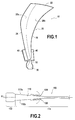
- the invention is applicable to the manufacture of any turbomachine blade with integrated plate (s) -form (s) of composite material, and particularly but not exclusively to fan blades such as that illustrated on the figure 1 .
- Dawn 10 of the figure 1 comprises, in a manner well known per se, a blade 20, a foot 30 formed by a portion of greater thickness, for example with a bulbous section, extended by a stilt 32, and two platforms 40 located between the stilt 32 and the blade 20.
- the blade 20 extends longitudinally between the platforms 40 and the top of the blade 22 and has in cross section a curved profile of variable thickness between its two opposite lateral edges (ie its leading edge 24 and its trailing edge 26).
- the blade 20 is connected to the platforms 40 on an external face thereof which delimit, inside, the annular air inlet channel in the blower, this vein being delimited by outer side by a housing (not shown).
- the blade 10 thus has two platforms 40 which extend from the lateral faces (underside face 20a and extrados face 20b) of the blade 20.
- the invention also applies to the blades which comprise only a single platform (which would extend for example from the upper surface of the blade, the intrados face being without platform).
- the figure 2 shows the arrangement of the layers of yarns in a 3D woven fiber blank 100 for the production of a fan blade such as that of the figure 1 .
- the fibrous blank 100 comprises a central portion 110 forming blade preform and foot and two side portions 120 intended to form, after shaping, platform preforms. These portions 110 and 120 of the blank extend generally in the direction X corresponding to the longitudinal direction of the blade to be produced. In this figure, only the envelopes of these two parts are shown.
- the central part 110 comprises two opposite lateral faces 110a, 110b from which the two lateral parts 120 extend. In the case of the production of a fan blade with a single platform, only one of these parts lateral would be present.
- the central part 110 has, in its part 112 intended to form a preform of foot, an extra thickness (between the lateral faces 110a, 110b) determined according to the thickness of the root of the blade to be produced. In its portion 114 intended to form a blade preform, the central portion 110 has a variable thickness determined according to the profile thickness of the blade of the blade to be produced.
- a fibrous preform having a shape close to that of the fan blade to be manufactured can be obtained from such a fibrous blank 100 in the following manner.
- the fibrous blank 100 is cut flat so that all woven over-lengths are removed and that the workpiece is the size of the injection mold.
- This cutting step relates in particular to the portion 112 of the blank intended to form a foot preform, the central portion 110 forming blade preform at its leading edge, its trailing edge and its top, and the end of the side portions 120 for forming platform preforms.
- the shaping of the blank is carried out by laying it flat and lifting one of the lateral parts to position it at 90 ° with respect to the corresponding lateral face of the central part. This position is blocked and the preform returned.
- the central part of the blank is then deformed to reproduce the curved profile of the blade.
- the other side portion is deployed at 90 ° relative to the corresponding lateral face of the central portion.
- the deposition of the matrix in the fiber preform is carried out by maintaining the preform in the mold at least until stiffening (or consolidation) of the preform.
- the matrix is of a nature chosen according to the intended application, for example an organic matrix obtained in particular from a polymer matrix precursor resin such as an epoxy, bismaleimide or polyimide resin, or a carbon matrix or a matrix ceramic.
- the fibrous preform is impregnated with a composition containing the matrix precursor resin, before conformation in a tool, or after conformation, the impregnation being in the latter case carried out for example by infusion or by a RTM type process ("Resin Transfer Molding").
- the densification may be carried out by chemical vapor infiltration, or CVI ("Chemical Vapor Infiltration") or by impregnation with a liquid composition containing a precursor resin of carbon or ceramic and thermal treatment of pyrolysis or ceramization of the precursor, these methods being well known per se.
- CVI Chemical Vapor Infiltration
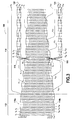
- the figure 3 shows a warp plane of a three-dimensional woven fibrous blank 100 for the production of a fibrous preform such as that of the figure 2 .
- warp plane of the fiber blank is meant here a plane perpendicular to the weft son containing a column of warp threads (on this figure 3 , the continuous lines represent the warp threads).
- the fiber blank comprises, between its opposite lateral faces 110a, 110b, for example 24 layers of warp threads c 1 to c 24 and as many weft layers t 1 at t 24 .
- the weave is of the interlock type with satin-type weave for the warp yarns c 1 and c 24 in the portions adjacent opposite side faces 110a, 110b.
- a 3D weave of a fibrous structure with an interlock type armor and a 2D or 3D armor skin satin type is known per se. We can refer to the document WO 2006/136755 .
- the thickness of the fiber blank between its side faces 110a, 110b is variable. Also, to account for this thinning of the profile of the blade to be manufactured, is gradually removed layers of warp son and as many weft son of the fiber blank. On the example of the figure 3 these are the warp threads c 2 , c 3 and c 4 which are successively removed from the lateral side 110a side, and the warp threads c 23 , c 22 and c 21 which are successively removed from the side of the opposite side face 110b. This manipulation consists in removing yarns during weaving the fibrous blank is known per se. We can refer to the document EP 1,528,285 .
- woven side portions 120 for forming platform preforms.
- layers of warp yarns are removed from the fiber blank on the side of each side face and woven with certain layers of weft yarns.
- the adjacent warp threads c 5 to c 7 which are removed from the lateral side 110a side and woven with weft threads t 1 to t 3 to form one of the side portions 120.
- the adjacent warp yarns c 18 to c 20 are withdrawn from the side of the other side face 110b and woven with weft yarns t 22 to t 24 to form the other of the side portions 120.
- Deliveries are made between the layers of warp yarn forming the portions 120 and the warp yarn layers of the portion 114 for forming a blade preform.
- the warp yarns removed from the fiber blank to take account of the degression the thickness of the profile of the blade are reintroduced in the portion 114 of the fibrous blank at the level of the zone 116 (here the warp threads c 3 and c 4 on the side of the side face 110a and c 21 , c 22 and 23 on the side side side 110b).
- these warp threads cross the warp threads c 5 to c 7 (on the side of the side face 110a) and c 18 to c 20 (on the side of the side face 110b), preferably at the connections between the part 114 corresponding to the blade preform and the side portions 120 corresponding to the platform preforms.
- the warp threads c 3 and c 4 on the side of the lateral face 110a and c 21 , c 22 and c 23 on the side of the lateral face 110b are left floated (that is to say they remain at the surface of the fibrous blank without being interwoven with the weft yarns) between their exit zone of the portion 114 of the fibrous blank and their reintroduction zone 116 therein. If the degressivity of the thickness of the blade profile requires it, at least some of these warp son may be released further downstream of the portion 114 of the fiber blank. On the example of the figure 3 this is the case for the warp threads c 3 , c 21 , c 22 and c 23 . In the subsequent stage of implementation form of the fibrous blank, the portion of these warp son c 3 , c 21 , c 22 and c 23 between their areas of exit and insertion in the fiber blank is cut.
- the figure 3 represents an embodiment of the crossing between the reintroduced warp threads in the portion 114 of the fibrous blank at the level of the zone 116 and the warp threads issued from the latter to weave the lateral parts 120 intended to form flat preforms -form.
- other known types of cross may be used, especially in order to avoid crossings too brutal.
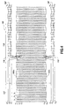
- the figure 4 shows a chain plane of a fibrous blank 100 'intended for the production of a fibrous preform of turbomachine fan blade and made according to another mode of weaving.
- the profile of the blade of the blade to be manufactured does not have a degression of its thickness at least on the lower part of the blade which extends beyond the platforms (the thickness remains constant).
- the fiber blank 100' comprises, between its opposite lateral faces 110 'a, 110' b, 24 layers of c 1 to c 24 warp yarns and as many weft layers t 1 to t 24 .
- the weave is of the interlock type with a satin type weave for the warp yarns c 1 and c 24 in the portions adjacent to the opposite side faces.
- the thickness of the fibrous blank between its side faces 110'a, 110'b remains constant, so that no exit layer of son is performed.
- the adjacent warp threads c 5 to c 7 are removed from the lateral side side 110'a and woven with weft threads t 1 to t 3 to form one of the side portions 120 '.
- the adjacent c 18 to c 20 warp yarns are removed from the side of the other side face 110'b and woven with weft yarns t 22 to t 24 to form the other of the side portions 120 '.
- chain yarns c' 1 to c ' 3 and c' 21 to and 23 ' are introduced into the portion 114 'of the fibrous blank at the zone 116'.
- these warp threads cross the warp threads c 5 to c 7 (on the side of the side face 110 'a) and c 18 to c 20 (on the side of the side face 110' b), preferably at the connections between the portion 114 'corresponding to the blade preform and the side portions 120' corresponding to the platform preforms.
- the output of layers of son to weave the preform thereof will be operated only on the side of one of the side faces of the fibrous blank. This solution allows more flexibility if one has only few layers of son to weave this platform preform.
- the variation of the thickness of the blade of the blade to be manufactured can be obtained by using weft son of variable title.
- This alternative makes it possible to avoid having to remove layers of yarn from the fibrous blank to reintroduce them a little further downstream.
Landscapes
- Engineering & Computer Science (AREA)
- Textile Engineering (AREA)
- Mechanical Engineering (AREA)
- Chemical & Material Sciences (AREA)
- Composite Materials (AREA)
- Materials Engineering (AREA)
- General Engineering & Computer Science (AREA)
- Woven Fabrics (AREA)
- Turbine Rotor Nozzle Sealing (AREA)
- Structures Of Non-Positive Displacement Pumps (AREA)
- Reinforced Plastic Materials (AREA)
Description
La présente invention concerne la réalisation d'une préforme fibreuse d'aube munie d'au moins une plate-forme, notamment pour la fabrication d'une aube de turbomachine en matériau composite.The present invention relates to the production of a blade fiber preform provided with at least one platform, in particular for the manufacture of a turbomachine blade of composite material.
La réalisation d'aubes en matériau composite pour des turbomachines a déjà été proposé. On pourra se référer par exemple au document
Par ailleurs, une soufflante de turbomachine comprend des plates-formes qui sont disposées entre les aubes afin de délimiter, du côté intérieur, la veine annulaire d'entrée d'air dans la soufflante, cette veine étant délimitée du côté extérieur par un carter. Ces plates-formes peuvent être rapportées séparément ou être intégrées directement à la base des aubes de soufflante, entre l'échasse prolongeant leur pied et la pale de celles-ci. L'invention s'intéresse plus particulièrement aux aubes appartenant à cette seconde catégorie, c'est-à-dire à plate(s)-forme(s) intégrée(s).Furthermore, a turbomachine blower comprises platforms which are arranged between the blades in order to delimit, on the inside, the annular air intake duct in the blower, this duct being delimited on the outside by a casing. These platforms can be reported separately or be integrated directly at the base of the fan blades, between the stilt extending their foot and the blade thereof. The invention is more particularly concerned with blades belonging to this second category, that is to say with integrated platform (s).
Un structure fibreuse selon le préambule de la revendication 1 et un procédé selon le préambule de la revendication 11 sont connu du document
Il est donc souhaitable de pouvoir disposer d'aubes de turbomachine à plate(s)-forme(s) intégrée(s) en matériau composite, notamment mais non exclusivement en matériau composite à matrice organique (CMO).It is therefore desirable to have turbomachine blades with a platform (s) -form (s) integrated (s) composite material, including but not exclusively organic matrix composite material (CMO).
A cet effet, selon l'invention, il est proposé un procédé de réalisation d'une préforme fibreuse pour la fabrication d'une aube de turbomachine en matériau composite, l'aube ayant une pale s'étendant selon une direction longitudinale et présentant deux faces latérales opposées et au moins une plate-forme s'étendant à partir d'une face latérale, le procédé comprenant :
- la réalisation par tissage tridimensionnel d'une ébauche fibreuse en une seule pièce avec une pluralité de couches de fils longitudinaux s'étendant dans une direction correspondant à la direction longitudinale de l'aube à fabriquer et liées entre elles par des fils d'une pluralité de couches de fils transversaux ; et
- la mise en forme de l'ébauche fibreuse pour obtenir une préforme fibreuse en une seule pièce ayant une première partie formant préforme de pale et au moins une seconde partie formant préforme de plate-forme ;
- au cours du tissage de l'ébauche fibreuse, des fils d'un premier groupe de fils longitudinaux sont sortis de l'ébauche fibreuse du côté de l'une au moins des faces latérales de l'ébauche fibreuse pour former une partie de l'ébauche correspondant à une préforme de plate-forme d'aube, et des fils d'un deuxième groupe de fils longitudinaux sont insérés dans l'ébauche fibreuse avec un croisement mutuel entre les fils du premier groupe et les fils du deuxième groupe.
- three-dimensional weaving of a one-piece fibrous blank with a plurality of longitudinal yarn layers extending in a direction corresponding to the longitudinal direction of the blade to be made and interconnected by wires of a plurality of transverse wire layers; and
- shaping the fiber blank to obtain a one-piece fiber preform having a first blade preform portion and at least a second platform preform portion;
- during the weaving of the fibrous blank, threads of a first group of longitudinal threads are taken out of the fibrous blank on the side of at least one of the side faces of the fibrous blank to form a part of the blank corresponding to a blade platform preform, and yarns of a second group of longitudinal yarns are inserted into the fiber blank with a mutual cross between the yarns of the first group and the yarns of the second group.
En réalisant au cours du tissage un croisement entre des fils sortis de l'ébauche fibreuse et des fils insérés dans celle-ci, il est possible d'obtenir une préforme fibreuse en une seule pièce par tissage tridimensionnel avec une partie formant préforme de pale et une autre partie formant la préforme de plate-forme tout en maintenant un taux de fibres constant dans l'ébauche fibreuse malgré la sortie des fils du premier groupe.By performing during the weaving a cross between threads exiting the fibrous blank and son inserted therein, it is possible to obtain a one-piece fibrous preform by three-dimensional weaving with a blade preform portion and another part forming the platform preform while maintaining a constant fiber content in the fibrous blank despite the output of the son of the first group.
On assure également une continuité des fibres entre la partie de la préforme formant pale et la partie formant plate-forme, ce qui permet de conférer les propriétés mécaniques requises pour une aube à plate-forme intégrée.Fiber continuity is also provided between the portion of the blade preform and the platform portion, thereby providing the mechanical properties required for an integrated platform blade.
Selon une particularité du procédé, le croisement entre les fils du premier groupe et les fils du deuxième groupe est effectué à proximité d'un raccordement entre la partie de l'ébauche correspondant à la préforme de plate-forme d'aube et la partie de l'ébauche correspondant à la préforme de pale.According to a feature of the method, the crossing between the son of the first group and the son of the second group is performed near a connection between the part of the blank corresponding to the blade platform preform and the part of the blank corresponding to the blade preform.
De préférence, les fils du deuxième groupe de fils qui sont insérés dans l'ébauche fibreuse proviennent de couches de fils longitudinaux préalablement sorties de l'ébauche fibreuse afin d'obtenir une réduction de l'épaisseur de l'ébauche sur sa largeur. Des couches de fils peuvent en effet être sorties de l'ébauche pour tenir compte de la réduction de l'épaisseur du profil de la pale (depuis le pied vers le sommet de l'aube). Leur utilisation pour réaliser la plate-forme est donc particulièrement avantageuse puisqu'elle évite leur gaspillage.Preferably, the yarns of the second group of yarns which are inserted into the fiber blank come from layers of longitudinal yarns previously removed from the fiber blank in order to obtain a reduction in the thickness of the blank over its width. Layers of wires can indeed be removed from the blank to take into account the reduction in the thickness of the profile of the blade (from the foot to the top of dawn). Their use to realize the platform is particularly advantageous since it avoids their waste.
Dans ce cas, la mise en forme de l'ébauche fibreuse comprend avantageusement la découpe de la portion des fils du deuxième groupe de fils située entre les zones de sortie et d'insertion dans l'ébauche fibreuse. De plus, certains au moins des fils du deuxième groupe de fils peuvent être sortis de l'ébauche fibreuse en aval de leur zone d'insertion dans ladite ébauche fibreuse afin d'obtenir une réduction de l'épaisseur de l'ébauche sur sa largeur en aval de la partie de l'ébauche correspondant à la préforme de plate-forme d'aube.In this case, the shaping of the fibrous blank advantageously comprises cutting the portion of the son of the second group of son located between the exit and insertion areas in the fiber blank. In addition, at least some of the yarns of the second group of yarns may be taken out of the fibrous blank downstream of their insertion zone in said fibrous blank in order to obtain a reduction in the thickness of the blank over its width. downstream of the portion of the blank corresponding to the blade platform preform.
Lorsque le profil de la pale de l'aube ne présente pas de réduction de son épaisseur entre le pied et le sommet de l'aube, ou lorsque cette réduction d'épaisseur ne permet de disposer d'une quantité suffisante de fils pour former la plate-forme de l'aube, certains au moins des fils du deuxième groupe de fils qui sont insérés dans l'ébauche fibreuse peuvent provenir de couches de fils longitudinaux rapportées.When the profile of the blade of the blade does not have a reduction in its thickness between the foot and the top of the blade, or when this reduction in thickness does not allow to have a sufficient amount of son to form the dawn platform, at least some of the threads of the second group of threads that are inserted into the fibrous blank can come from longitudinal thread layers reported.
Selon une autre particularité du procédé, la sortie et l'insertion de fils dans l'ébauche fibreuse est réalisée pour chacune des faces latérales de l'ébauche fibreuse pour former une partie de l'ébauche correspondant à deux préformes de plate-forme d'aube. Dans ce cas, l'aube qui sera fabriquée présentera deux plates-formes de chaque côté (intrados et extrados).According to another feature of the method, the output and the insertion of threads into the fibrous blank is carried out for each of the lateral faces of the fibrous blank to form a part of the blank corresponding to two platform preforms. dawn. In this case, the dawn that will be manufactured will present two platforms on each side (intrados and extrados).
Selon encore une autre particularité du procédé, la mise en forme de l'ébauche fibreuse comprend la découpe de la partie de l'ébauche correspondant à la préforme de plate-forme d'aube aux dimensions voulues et le déploiement de cette partie de l'ébauche selon une direction sensiblement orthogonale à sa face latérale.According to yet another feature of the method, the shaping of the fibrous blank comprises cutting the part of the blank corresponding to the blade platform preform to the desired dimensions and the deployment of this part of the blank in a direction substantially orthogonal to its side face.
Les fils longitudinaux s'étendant dans une direction correspondant à la direction longitudinale de l'aube à fabriquer peuvent être des fils de chaîne. Alternativement, les fils longitudinaux s'étendant dans une direction correspondant à la direction longitudinale de l'aube à fabriquer peuvent être des fils de trame.The longitudinal son extending in a direction corresponding to the longitudinal direction of the blade to be manufactured may be warp son. Alternatively, the longitudinal son extending in a direction corresponding to the longitudinal direction of the blade to be manufactured may be weft son.
L'invention a également pour objet une préforme fibreuse d'une aube de turbomachine ayant une pale s'étendant selon une direction longitudinale et présentant deux faces latérales opposées et au moins une plate-forme s'étendant à partir d'une face latérale, la préforme comprenant une ébauche fibreuse tissée en une seule pièce par tissage tridimensionnel avec une pluralité de couches de fils longitudinaux s'étendant dans une direction correspondant à la direction longitudinale de l'aube à fabriquer et liées entre elles par des fils d'une pluralité de couches de fils transversaux, et dans laquelle, conformément à l'invention, des fils d'un premier groupe de fils longitudinaux sont sortis de l'ébauche fibreuse du côté de l'une au moins des faces latérales de l'ébauche fibreuse pour former une partie de l'ébauche correspondant à une préforme de plate-forme d'aube, et des fils d'un deuxième groupe de fils longitudinaux sont insérés dans l'ébauche fibreuse avec un croisement mutuel entre les fils du premier groupe et les fils du deuxième groupe.The invention also relates to a fiber preform of a turbomachine blade having a blade extending in a longitudinal direction and having two opposite side faces and at least one platform extending from a side face, the preform comprising a one-piece woven fiber blank by three-dimensional weaving with a plurality of longitudinal yarn layers extending in a direction corresponding to the longitudinal direction of the blade to be made and bonded together by yarns of a plurality of layers of transverse yarns, and wherein, in accordance with the invention, yarns of a first group of longitudinal yarns are taken out of the fiber blank on the side of at least one of the side faces of the fiber blank to form a part of the blank corresponding to a blade platform preform, and threads of a second group of longitudinal threads are inserted into the fiber blank with a cross between the threads of the first group and the threads of the second group. group.
L'invention a aussi pour objet une aube de soufflante de turbomachine en matériau composite comprenant une préforme fibreuse telle que définie précédemment et densifiée par une matrice. L'invention a encore pour objet une soufflante de turbomachine comprenant au moins une telle aube.The invention also relates to a turbomachine fan blade of composite material comprising a fiber preform as defined above and densified by a matrix. The invention further relates to a turbomachine blower comprising at least one such blade.
D'autres caractéristiques et avantages de la présente invention ressortiront de la description faite ci-dessous, en référence aux dessins annexés qui en illustrent des exemples de réalisation dépourvus de tout caractère limitatif. Sur les figures :
- la
figure 1 est une vue en perspective d'une aube de soufflante de turbomachine à deux plates-formes intégrées ; - la
figure 2 illustre de façon très schématique la disposition des couches de fils dans une ébauche fibreuse tissée 3D destinée à la réalisation d'une aube de soufflante telle que celle de lafigure 1 ; - la
figure 3 est une vue schématique d'un plan de chaîne montrant un mode de tissage de l'ébauche fibreuse de lafigure 2 ; et - la
figure 4 est une vue schématique d'un plan de chaîne montrant un autre mode de tissage pour la réalisation d'une ébauche fibreuse selon une variante de réalisation de l'invention.
- the
figure 1 is a perspective view of a turbomachine fan blade with two integrated platforms; - the
figure 2 illustrates very schematically the arrangement of the son layers in a 3D woven fiber blank for the realization of a fan blade such as that of thefigure 1 ; - the
figure 3 is a schematic view of a chain plane showing a method of weaving the fiber blank of thefigure 2 ; and - the
figure 4 is a schematic view of a chain plane showing another embodiment of weaving for producing a fiber blank according to an alternative embodiment of the invention.
L'invention est applicable à la fabrication de toute aube de turbomachine à plate(s)-forme(s) intégrée(s) en matériau composite, et notamment mais non exclusivement aux aubes de soufflante telles que celle illustrée sur la
L'aube 10 de la
La pale 20 s'étend en direction longitudinale entre les plates-formes 40 et le sommet de l'aube 22 et présente en section transversale un profil incurvé d'épaisseur variable entre ses deux bords latéraux opposés (i.e. son bord d'attaque 24 et son bord de fuite 26).The
A son extrémité radiale interne, la pale 20 se raccorde aux plates-formes 40 sur une face externe de celles-ci qui délimitent, à l'intérieur, la veine annulaire d'entrée d'air dans la soufflante, cette veine étant délimitée du côté extérieur par un carter (non représenté).At its inner radial end, the
Dans l'exemple de la
La
L'ébauche fibreuse 100 comprend une partie centrale 110 formant préforme de pale et de pied et deux parties latérales 120 destinées à former, après mise en forme, préformes de plate-forme. Ces parties 110 et 120 de l'ébauche s'étendent de façon générale dans la direction X correspondant à la direction longitudinale de l'aube à réaliser. Sur cette figure, seules les enveloppes de ces deux parties sont représentées.The fibrous blank 100 comprises a
La partie centrale 110 comprend deux faces latérales opposées 110a, 110b à partir desquelles s'étendent les deux parties latérales 120. Dans le cas de la réalisation d'une aube de soufflante à une seule plate-forme, seule l'une de ces parties latérales serait présente.The
La partie centrale 110 présente, dans sa partie 112 destinée à former une préforme de pied, une surépaisseur (entre les faces latérales 110a, 110b) déterminée en fonction de l'épaisseur du pied de l'aube à réaliser. Dans sa partie 114 destinée à former une préforme de pale, la partie centrale 110 présente une épaisseur variable déterminée en fonction de l'épaisseur de profil de la pale de l'aube à réaliser.The
Succinctement, une préforme fibreuse ayant une forme proche de celle de l'aube de soufflante à fabriquer peut être obtenue à partir d'une telle ébauche fibreuse 100 de la façon suivante. Après un contrôle qualité, l'ébauche fibreuse 100 est découpée à plat afin que toutes les sur-longueurs tissées soient éliminées et que la pièce soit aux dimensions du moule d'injection. Cette étape de découpe concerne en particulier la partie 112 de l'ébauche destinée à former une préforme de pied, la partie centrale 110 formant préforme de pale au niveau de son bord d'attaque, son bord de fuite et de son sommet, et l'extrémité des parties latérales 120 destinées à former préformes de plate-forme.Briefly, a fibrous preform having a shape close to that of the fan blade to be manufactured can be obtained from such a fibrous blank 100 in the following manner. After a quality control, the fibrous blank 100 is cut flat so that all woven over-lengths are removed and that the workpiece is the size of the injection mold. This cutting step relates in particular to the
Une fois les découpes réalisées, la mise en forme de l'ébauche est réalisée en la mettant à plat et en relevant l'une des parties latérales pour la positionner à 90° par rapport à la face latérale correspondante de la partie centrale. Cette position est bloquée et la préforme retournée. La partie centrale de l'ébauche est ensuite déformée pour reproduire le profil incurvé de l'aube. Puis, l'autre partie latérale est déployée à 90° par rapport à la face latérale correspondante de la partie centrale. On obtient ainsi une préforme fibreuse en une seule pièce avec une partie formant préforme de pale et de pied et deux parties formant préformes de plate-forme. La préforme fibreuse ainsi obtenue est ensuite séchée et mise en place dans le moule d'injection.Once the cuts are made, the shaping of the blank is carried out by laying it flat and lifting one of the lateral parts to position it at 90 ° with respect to the corresponding lateral face of the central part. This position is blocked and the preform returned. The central part of the blank is then deformed to reproduce the curved profile of the blade. Then, the other side portion is deployed at 90 ° relative to the corresponding lateral face of the central portion. Thus, a one-piece fiber preform with a blade and foot preform part and two platform preform parts is obtained. The fibrous preform thus obtained is then dried and placed in the injection mold.
Le dépôt de la matrice dans la préforme fibreuse est réalisée en maintenant la préforme dans le moule au moins jusqu'à rigidification (ou consolidation) de la préforme. La matrice est de nature choisie en fonction de l'application envisagée, par exemple une matrice organique obtenue notamment à partir d'une résine précurseur de matrice polymère telle qu'une résine époxyde, bismaléimide ou polyimide, ou une matrice en carbone ou une matrice en céramique. Dans le cas d'une matrice organique, la préforme fibreuse est imprégnée par une composition contenant la résine précurseur de matrice, avant conformation dans un outillage, ou après conformation, l'imprégnation étant dans ce dernier cas réalisée par exemple par infusion ou par un processus de type RTM ("Resin Transfer Moulding"). Dans le cas d'une matrice en carbone ou en céramique, la densification pourra être réalisée par infiltration chimique en phase gazeuse, ou CVI ("Chemical Vapor Infiltration") ou par imprégnation par une composition liquide contenant une résine précurseur de carbone ou de céramique et traitement thermique de pyrolyse ou céramisation du précurseur, ces procédés étant bien connus en soi.The deposition of the matrix in the fiber preform is carried out by maintaining the preform in the mold at least until stiffening (or consolidation) of the preform. The matrix is of a nature chosen according to the intended application, for example an organic matrix obtained in particular from a polymer matrix precursor resin such as an epoxy, bismaleimide or polyimide resin, or a carbon matrix or a matrix ceramic. In the case of an organic matrix, the fibrous preform is impregnated with a composition containing the matrix precursor resin, before conformation in a tool, or after conformation, the impregnation being in the latter case carried out for example by infusion or by a RTM type process ("Resin Transfer Molding"). In the case of a carbon or ceramic matrix, the densification may be carried out by chemical vapor infiltration, or CVI ("Chemical Vapor Infiltration") or by impregnation with a liquid composition containing a precursor resin of carbon or ceramic and thermal treatment of pyrolysis or ceramization of the precursor, these methods being well known per se.
Des modes de tissage tridimensionnel de l'ébauche fibreuse 100 seront maintenant décrits plus en détail.Three-dimensional weaving patterns of the
Il est supposé que le tissage est réalisé avec des fils de chaîne s'étendant dans la direction longitudinale X de l'ébauche, étant noté qu'un tissage avec des fils de trame dans cette direction est également possible.It is assumed that the weave is made with warp yarns extending in the longitudinal direction X of the blank, being noted that weaving with weft yarns in this direction is also possible.
La
Au niveau de sa partie 112 destinée à former une préforme de pied, l'ébauche fibreuse comprend, entre ses faces latérales opposées 110a, 110b, par exemple 24 couches de fils de chaîne c1 à c24 et autant de couches de trame t1 à t24. Dans cette partie 112, l'armure de tissage est de type interlock avec un tissage de type satin pour les fils de chaîne c1 et c24 dans les parties adjacentes aux faces latérales opposées 110a, 110b. Un tissage 3D d'une structure fibreuse avec une armure de type interlock à coeur et une armure 2D ou 3D de type satin en peau est connu en soi. On pourra se référer au document
Au niveau de la partie 114 destinée à former une préforme de pale, l'épaisseur de l'ébauche fibreuse entre ses faces latérales 110a, 110b est variable. Aussi, pour tenir compte de cet amincissement du profil de l'aube à fabriquer, on retire au fur et à mesure des couches de fils de chaîne et autant de fils de trame de l'ébauche fibreuse. Sur l'exemple de la
Au niveau d'une zone 116 de la partie 114 de l'ébauche fibreuse sont tissées les parties latérales 120 destinées à former préformes de plate-forme. A cet effet, des couches de fils de chaîne sont retirées de l'ébauche fibreuse du côté de chaque face latérale et tissées avec certaines couches de fils de trame. Sur l'exemple de la
Par ailleurs, pour maintenir un taux de fibres constant dans l'ébauche fibreuse malgré le retrait de ces fils de chaîne destinés à former les parties latérales 120, certains au moins des fils de chaîne retirés de l'ébauche fibreuse pour tenir compte de la dégressivité de l'épaisseur du profil de l'aube sont réintroduits dans la partie 114 de l'ébauche fibreuse au niveau de la zone 116 (ici les fils de chaîne c3 et c4 du côté de la face latérale 110a et c21, c22 et c23 du côté de la face latérale 110b). Ainsi, ces fils de chaîne viennent croiser les fils de chaîne c5 à c7 (du côté de la face latérale 110a) et c18 à c20 (du côté de la face latérale 110b), de préférence au niveau des raccordements entre la partie 114 correspondant à la préforme de pale et les parties latérales 120 correspondant aux préformes de plate-forme.Moreover, to maintain a constant fiber content in the fiber blank despite the removal of these warp yarns intended to form the
De la sorte, les fils de chaîne c3 et c4 du côté de la face latérale 110a et c21, c22 et c23 du côté de la face latérale 110b sont laissés flottés (c'est-à-dire qu'ils restent en surface de l'ébauche fibreuse sans être entrelacés avec les fils de trame) entre leur zone de sortie de la partie 114 de l'ébauche fibreuse et leur zone 116 de réintroduction dans celle-ci. Si la dégressivité de l'épaisseur du profil de pale le nécessite, certains au moins de ces fils de chaîne pourront être à nouveau sortis plus en aval de la partie 114 de l'ébauche fibreuse. Sur l'exemple de la
La
La
Dans cet autre exemple de réalisation, le profil de la pale de l'aube à fabriquer ne présente pas de dégressivité de son épaisseur au moins sur la partie basse de la pale qui s'étend au-delà des plates-formes (l'épaisseur reste constante).In this other embodiment, the profile of the blade of the blade to be manufactured does not have a degression of its thickness at least on the lower part of the blade which extends beyond the platforms (the thickness remains constant).
Au niveau de sa partie 112' destinée à former une préforme de pied, l'ébauche fibreuse 100' comprend, entre ses faces latérales opposées 110'a, 110'b, 24 couches de fils de chaîne c1 à c24 et autant de couches de trame t1 à t24. Dans cette partie 112', l'armure de tissage est de type interlock avec un tissage de type satin pour les fils de chaîne c1 et c24 dans les parties adjacentes aux faces latérales opposées.At its portion 112 'intended to form a foot preform, the fiber blank 100' comprises, between its opposite lateral faces 110 'a, 110' b, 24 layers of c 1 to c 24 warp yarns and as many weft layers t 1 to t 24 . In this portion 112 ', the weave is of the interlock type with a satin type weave for the warp yarns c 1 and c 24 in the portions adjacent to the opposite side faces.
Au niveau de la partie 114' destinée à former une préforme de pale, l'épaisseur de l'ébauche fibreuse entre ses faces latérales 110'a, 110'b reste constante, de sorte qu'aucune sortie de couche de fils n'est réalisée.At the portion 114 'intended to form a blade preform, the thickness of the fibrous blank between its side faces 110'a, 110'b remains constant, so that no exit layer of son is performed.
Comme pour l'exemple précédemment décrit, au niveau d'une zone 116' de la partie 114' de l'ébauche fibreuse sont tissées les parties latérales 120' destinées à former préformes de plate-forme. A cet effet, sur l'exemple de la
Pour maintenir un taux de fibres constant dans l'ébauche fibreuse malgré le retrait de ces fils de chaîne destinés à former les parties latérales 120', des fils de chaîne c'1 à c'3 et c'21 à et c'23 rapportés sont introduits dans la partie 114' de l'ébauche fibreuse au niveau de la zone 116'. Ainsi, ces fils de chaîne viennent croiser les fils de chaîne c5 à c7 (du côté de la face latérale 110'a) et c18 à c20 (du côté de la face latérale 110'b), de préférence au niveau des raccordements entre la partie 114' correspondant à la préforme de pale et les parties latérales 120' correspondant aux préformes de plate-forme.In order to maintain a constant fiber content in the fibrous blank despite the removal of these warp yarns intended to form the side portions 120 ', chain yarns c' 1 to c ' 3 and c' 21 to and 23 ' are introduced into the portion 114 'of the fibrous blank at the
D'autres variantes de tissage de l'ébauche fibreuse selon l'invention peuvent être envisagées.Other weaving variants of the fibrous blank according to the invention can be envisaged.
Notamment, dans le cas où l'aube à fabriquer ne présente qu'une seule plate-forme, la sortie de couches de fils pour tisser la préforme de celle-ci ne serait opérée que du côté de l'une des faces latérales de l'ébauche fibreuse. Cette solution permet d'avoir davantage de flexibilité si l'on ne dispose que de peu de couches de fils pour tisser cette préforme de plate-forme.In particular, in the case where the blade to be manufactured has only one platform, the output of layers of son to weave the preform thereof will be operated only on the side of one of the side faces of the fibrous blank. This solution allows more flexibility if one has only few layers of son to weave this platform preform.
Il est également possible de réaliser une préforme fibreuse présentant des préformes de demi plate-forme s'étendant à partir de ses faces latérales. Dans ce cas, les demies plates-formes de l'aube fabriquée à partir d'une telle préforme ne couvrent pas entièrement l'espacement entre deux aubes adjacentes et il est nécessaire de réaliser indépendamment les demies plates-formes manquantes. La réalisation de ces dernières est toutefois relativement aisée puisque leur tissage n'a pas besoin de prendre en compte la cambrure de pale.It is also possible to produce a fiber preform having half-platform preforms extending from its side faces. In this case, the half platforms of the blade made from such a preform do not fully cover the spacing between two adjacent blades and it is necessary to independently realize the missing half platforms. The realization of the latter is however relatively easy since their weaving does not need to take into account the blade arch.
Selon une alternative de tissage de la
Selon une autre alternative de tissage de l'ébauche fibreuse, il est possible de dédoubler les fils de chaîne constitutifs de préformes de plate-forme et de les tisser côte à côte afin de faciliter leur sortie de l'ébauche fibreuse à l'emplacement précis du positionnement des plates-formes. According to another alternative weaving of the fibrous blank, it is possible to split the constituent warp son of platform preforms and weave them side by side to facilitate their exit from the fiber blank at the precise location platform positioning.
Claims (15)
- A method of making a fiber preform for fabricating a turbine engine blade out of composite material, the blade (10) having an airfoil (20) extending in a longitudinal direction and presenting two opposite side faces (24, 26) and at least one platform (40) extending from a side face, the method comprising:making a single-piece fiber blank (100 ; 100') by three-dimensional weaving with a plurality of longitudinal yarns (C1 to C24) extending in a direction corresponding to the longitudinal direction of the blade that is to be fabricated and interlinked by yarns of a plurality of transverse layers of yarns (t1 to t24);shaping the fiber blank to obtain a single-piece fiber preform having a first portion forming an airfoil preform and at least one second portion forming a platform preform;characterized in that, during the weaving of the fiber blank, yarns (c5 to c7, c18 to c20) of a first group of longitudinal yarns are extracted from the fiber blank beside at least one of the side faces (110a, 110b) of the fiber blank in order to form a portion (120) of the blank corresponding to a blade platform preform, and yarns (c3, c4, c21, c22 and c23 ; c'1 to c'3) of a second group of longitudinal yarns are inserted into the fiber blank with mutual crossing between the yarns of the first group and the yarns of the second group.
- A method according to claim 1, wherein the crossing between the yarns of the first group and the yarns of the second group takes place close to a connection between the portion of the blank corresponding to the blade platform preform and the portion of the blank corresponding to the airfoil preform.
- A method according to claim 1 or claim 2, wherein the yarns of the second group of yarns that are inserted into the fiber blank come from layers of longitudinal yarn previously extracted from the fiber blank in order to obtain a reduction in the thickness of the blank over its width.
- A method according to claim 3, wherein the shaping of the fiber blank includes cutting away the portions of the yarns of the second group of yarns that are situated between the zones where they are extracted from and inserted into the fiber blank.
- A method according to claim 3 or claim 4, wherein at least some of the yarns of the second group of yarns are extracted from the fiber blank downstream from the zone where they are inserted into said fiber blank in order to reduce the thickness of the blank over its width downstream from the portion of the blank that corresponds to the blade platform preform.
- A method according to claim 1 or claim 2, wherein at least some of the yarns of the second group of yarns that are inserted into the fiber blank come from additional layers of longitudinal yarns.
- A method according to any one of claims 1 to 6, wherein the yarns are extracted from and inserted into the fiber blank on each of the side faces of the fiber blank in order to form portions of the blank that correspond to two blade platform preforms.
- A method according to any one of claims 1 to 7, wherein the shaping of the fiber blank includes cutting the portion of the blank that corresponds to the blade platform preform to have the desired dimensions, and deploying said portion of the blank in a direction that is substantially orthogonal to its side face.
- A method according to any one of claims 1 to 8, wherein the longitudinal yarns extending in a direction corresponding to the longitudinal direction of the blade that is to be fabricated are warp yarns.
- A method according to any one of claims 1 to 8, wherein the longitudinal yarns extending in a direction corresponding to the longitudinal direction of the blade that is to be fabricated are weft yarns.
- A fiber preform for a turbine engine blade (10) having an airfoil (20) extending in a longitudinal direction and presenting two opposite side faces (24, 26) together with at least one platform (40) extending from a side face, the preform comprising a fiber blank (100, 100') woven as a single piece by three-dimensional weaving with a plurality of layers of longitudinal yarns (c1 to c24) extending in a direction corresponding to the longitudinal direction of the blade that is to be fabricated and interlinked by yarns of a plurality of layers of transverse yarns (t1 to t24), characterized in that yarns (c5 to c7, c18 to c20) of a first group of longitudinal yarns are extracted from the fiber blank beside at least one of the side faces (110a, 110b) of the fiber blank in order to form a portion (120) of the blank corresponding to a blade platform preform, and yarns (c3, c4, c21, c22 and c23 ; c'1 to c'3) of a second group of longitudinal yarns are inserted into the fiber blank, with mutual crossing between the yarns of the first group and the yarns of the second group.
- A preform according to claim 11, wherein the crossing between the yarns of the first group and the yarns of the second group takes place close to a connection between the portion of the blank that corresponds to a blade platform preform and the portion of the blank that corresponds to the airfoil preform.
- A preform according to claim 11 or claim 12, wherein yarns are extracted from and inserted into the fiber blank on each of the side faces of the fiber blank in order to form portions of the blank that correspond to two blade platform preforms.
- A turbine engine fan blade made of composite material and including a fiber preform according to any one of claims 11 to 13 densified by a matrix.
- A turbine engine fan including at least one blade according to claim 14.
Applications Claiming Priority (2)
| Application Number | Priority Date | Filing Date | Title |
|---|---|---|---|
| US201261584406P | 2012-01-09 | 2012-01-09 | |
| PCT/FR2013/050026 WO2013104852A2 (en) | 2012-01-09 | 2013-01-07 | Fibrous preform of a turbomachine blade made of composite material with in-built platform, and method of producing same |
Publications (2)
| Publication Number | Publication Date |
|---|---|
| EP2802701A2 EP2802701A2 (en) | 2014-11-19 |
| EP2802701B1 true EP2802701B1 (en) | 2016-11-16 |
Family
ID=47628361
Family Applications (1)
| Application Number | Title | Priority Date | Filing Date |
|---|---|---|---|
| EP13701834.7A Active EP2802701B1 (en) | 2012-01-09 | 2013-01-07 | Fibrous preform of a turbomachine blade made of composite material with in-built platform, and method of producing same |
Country Status (9)
| Country | Link |
|---|---|
| US (1) | US9771810B2 (en) |
| EP (1) | EP2802701B1 (en) |
| JP (1) | JP6038178B2 (en) |
| CN (1) | CN104040056B (en) |
| BR (1) | BR112014016859B1 (en) |
| CA (1) | CA2862685C (en) |
| IN (1) | IN2014DN05637A (en) |
| RU (1) | RU2612628C2 (en) |
| WO (1) | WO2013104852A2 (en) |
Families Citing this family (33)
| Publication number | Priority date | Publication date | Assignee | Title |
|---|---|---|---|---|
| CN105026123B (en) * | 2012-11-13 | 2018-02-09 | 斯内克马公司 | Monolithic prefabricated component and blade for turbine |
| FR3011253B1 (en) * | 2013-10-01 | 2016-06-10 | Snecma | FIBROUS STRUCTURE WITH FLEET COMBINATION |
| FR3018473B1 (en) | 2014-03-17 | 2016-04-08 | Snecma | METHOD FOR MANUFACTURING A CAMERA PLATFORM IN COMPOSITE MATERIAL WITH INTEGRATED JOINTS FOR TURBOMACHINE BLOWER |
| FR3021349B1 (en) | 2014-05-22 | 2021-07-02 | Herakles | METHOD OF MANUFACTURING A TURBOMACHINE VANE FROM COMPOSITE MATERIAL, THUS OBTAINED VANE AND TURBOMACHINE INCORPORATING IT |
| FR3037097B1 (en) | 2015-06-03 | 2017-06-23 | Snecma | COMPOSITE AUBE COMPRISING A PLATFORM WITH A STIFFENER |
| FR3032462B1 (en) | 2015-02-10 | 2017-03-10 | Aircelle Sa | METHOD FOR MANUFACTURING A WOVEN REINFORCED FIBER PREFORM COMPRISING AN EVOLUTIVE SECTION |
| FR3035677B1 (en) | 2015-04-29 | 2017-05-12 | Snecma | DAWN HAVING PLATFORMS HAVING HOISTING PORTIONS |
| FR3035675B1 (en) | 2015-04-29 | 2017-05-12 | Snecma | DAWN WITH PLATFORMS COMPRISING INSERTS |
| FR3035678B1 (en) * | 2015-04-29 | 2017-05-12 | Snecma | DAWN WITH PLATFORMS HAVING A RESTRAINT LEG |
| FR3035676B1 (en) | 2015-04-29 | 2017-05-12 | Snecma | DAWN WITH PLATFORMS POSSESSING A STIFFENER |
| CN105544060A (en) * | 2016-01-29 | 2016-05-04 | 上海仪耐新材料科技有限公司 | Embedded type stitched three-dimensional bullet-proof fabric |
| US10436036B2 (en) * | 2016-07-05 | 2019-10-08 | Safran Aircraft Engines | Fitted platform for a turbine engine fan, and a method of fabricating it |
| US20180171806A1 (en) * | 2016-12-21 | 2018-06-21 | Rolls-Royce North American Technologies, Inc. | Three-dimensionally woven ceramic matrix composite turbine blade |
| FR3063448B1 (en) | 2017-03-01 | 2019-04-05 | Safran Aircraft Engines | PREFORME AND AUBE MONOBLOC FOR TURBOMACHINE |
| JP6790967B2 (en) * | 2017-03-31 | 2020-11-25 | 株式会社豊田自動織機 | Fiber structure and fiber reinforced composite |
| JP6700615B2 (en) * | 2017-03-31 | 2020-05-27 | 株式会社豊田自動織機 | Fiber structure and fiber reinforced composite material |
| FR3066531B1 (en) | 2017-05-19 | 2019-05-03 | Safran Aircraft Engines | DAWN IN COMPOSITE MATERIAL AND INTEGRATED PLATFORM FOR AN AIRCRAFT TURBOMACHINE |
| FR3082854B1 (en) * | 2018-06-25 | 2020-09-11 | Safran Ceram | FIBROUS STRUCTURE AND PART IN COMPOSITE MATERIAL INCORPORATING SUCH STRUCTURE |
| WO2019097147A1 (en) | 2017-11-14 | 2019-05-23 | Safran Ceramics | Fibrous structure and component made of composite material incorporating such a structure |
| FR3076814B1 (en) * | 2018-01-12 | 2020-01-31 | Safran Aircraft Engines | BLADE OR COMPOSITE PROPELLER BLADE WITH INTEGRATED LONGER FOR AIRCRAFT |
| US20190390555A1 (en) * | 2018-06-22 | 2019-12-26 | United Technologies Corporation | Composite airfoil with cleft in platform |
| FR3091723B1 (en) * | 2019-01-15 | 2021-04-02 | Safran Aircraft Engines | Composite blade or propeller blade for aircraft incorporating a shaping part |
| FR3092034B1 (en) * | 2019-01-30 | 2022-12-02 | Safran Aircraft Engines | Casing in composite material with local thickness variation |
| FR3093297B1 (en) * | 2019-02-28 | 2022-08-12 | Safran Aircraft Engines | METHOD FOR MAKING A WOVEN PIECE TAKING ACCOUNT OF OFF-FRAME |
| CN109972271B (en) * | 2019-03-27 | 2023-03-14 | 南京玻璃纤维研究设计院有限公司 | Variable thickness preform, composite component and yarn reducing method of variable thickness preform |
| US11434177B2 (en) | 2019-05-13 | 2022-09-06 | Rolls-Royce Plc | Ceramic matrix composite vane with hybrid construction |
| US12099894B2 (en) * | 2019-09-20 | 2024-09-24 | Rtx Corporation | Composite material marking and identification |
| FR3102392B1 (en) * | 2019-10-29 | 2021-10-08 | Safran | Woven fiber preform to make a blower blade in composite material |
| CN111365079A (en) * | 2020-04-01 | 2020-07-03 | 南京航空航天大学 | Ceramic matrix composite turbine rotor blade disk tenon connecting structure and turbine disk |
| FR3113647B1 (en) | 2020-08-27 | 2023-04-14 | Safran Aircraft Engines | NON-FLOWED PROPELLER WITH VARIABLE PITCH BLADE COMPRISING PLATFORMS WITH REDUCED DISTURBANCE |
| FR3120910A1 (en) * | 2021-03-17 | 2022-09-23 | Safran Aircraft Engines | Composite turbomachine part formed of a core surrounded by two 3D woven fiber preforms |
| CN115949471B (en) * | 2023-01-04 | 2023-12-22 | 北京航空航天大学 | Orthogonal three-dimensional woven composite material outlet guide vane and manufacturing method thereof |
| US11846192B1 (en) | 2023-04-21 | 2023-12-19 | General Electric Company | Airfoil assembly with a trunnion and spar |
Family Cites Families (16)
| Publication number | Priority date | Publication date | Assignee | Title |
|---|---|---|---|---|
| JPH0772482B2 (en) * | 1991-12-26 | 1995-08-02 | 工業技術院長 | Radial rotor and manufacturing method thereof |
| US6446675B1 (en) * | 2001-07-05 | 2002-09-10 | Albany International Techniweave, Inc. | Minimum distortion 3D woven preforms |
| WO2003023104A1 (en) * | 2001-09-12 | 2003-03-20 | Lockheed Martin Corporation | Woven preform for structural joints |
| FR2861143B1 (en) * | 2003-10-20 | 2006-01-20 | Snecma Moteurs | TURBOMACHINE BLADE, IN PARTICULAR BLADE OF BLOWER AND METHOD OF MANUFACTURING THE SAME |
| DE10350917B3 (en) | 2003-10-31 | 2005-05-25 | Rle International Produktentwicklungsgesellschaft Mbh | Transmission interruption-free manual transmission |
| FR2887601B1 (en) | 2005-06-24 | 2007-10-05 | Snecma Moteurs Sa | MECHANICAL PIECE AND METHOD FOR MANUFACTURING SUCH A PART |
| US7655581B2 (en) * | 2005-11-17 | 2010-02-02 | Albany Engineered Composites, Inc. | Hybrid three-dimensional woven/laminated struts for composite structural applications |
| US8079387B2 (en) * | 2008-10-29 | 2011-12-20 | Albany Engineered Composites, Inc. | Pi-shaped preform |
| FR2939129B1 (en) * | 2008-11-28 | 2014-08-22 | Snecma Propulsion Solide | TURBOMACHINE TURBINE IN COMPOSITE MATERIAL AND PROCESS FOR MANUFACTURING THE SAME. |
| FR2939153B1 (en) * | 2008-11-28 | 2011-12-09 | Snecma Propulsion Solide | REALIZING A FIBROUS STRUCTURE WITH AN EVOLVING THICKNESS THROUGH 3D WEAVING |
| FR2943942B1 (en) * | 2009-04-06 | 2016-01-29 | Snecma | PROCESS FOR MANUFACTURING A TURBOMACHINE BLADE OF COMPOSITE MATERIAL |
| FR2946999B1 (en) * | 2009-06-18 | 2019-08-09 | Safran Aircraft Engines | CMC TURBINE DISPENSER ELEMENT, PROCESS FOR MANUFACTURING SAME, AND DISPENSER AND GAS TURBINE INCORPORATING SAME. |
| FR2953885B1 (en) * | 2009-12-14 | 2012-02-10 | Snecma | TURBOMACHINE DRAFT IN COMPOSITE MATERIAL AND METHOD FOR MANUFACTURING THE SAME |
| FR2961846B1 (en) * | 2010-06-28 | 2012-08-03 | Snecma Propulsion Solide | TURBOMACHINE TURBOMACHINE WITH COMPLEMENTARY ASYMMETRIC GEOMETRY |
| FR2961845B1 (en) * | 2010-06-28 | 2013-06-28 | Snecma Propulsion Solide | TURBOMACHINE DAWN WITH COMPLEMENTARY PAIRE / IMPAIRE GEOMETRY AND METHOD OF MANUFACTURING THE SAME |
| EP2791473B1 (en) * | 2011-12-14 | 2019-02-06 | Safran Aircraft Engines | Fiber structure woven into a single part by means of 3d weaving, and use in the manufacture of a composite material part |
-
2013
- 2013-01-07 CA CA2862685A patent/CA2862685C/en active Active
- 2013-01-07 JP JP2014550750A patent/JP6038178B2/en active Active
- 2013-01-07 EP EP13701834.7A patent/EP2802701B1/en active Active
- 2013-01-07 RU RU2014132876A patent/RU2612628C2/en active
- 2013-01-07 WO PCT/FR2013/050026 patent/WO2013104852A2/en active Application Filing
- 2013-01-07 BR BR112014016859-8A patent/BR112014016859B1/en active IP Right Grant
- 2013-01-07 CN CN201380004969.XA patent/CN104040056B/en active Active
- 2013-01-07 US US14/371,220 patent/US9771810B2/en active Active
- 2013-01-07 IN IN5637DEN2014 patent/IN2014DN05637A/en unknown
Also Published As
| Publication number | Publication date |
|---|---|
| RU2014132876A (en) | 2016-02-27 |
| CA2862685A1 (en) | 2013-07-18 |
| BR112014016859A2 (en) | 2017-06-13 |
| WO2013104852A2 (en) | 2013-07-18 |
| CN104040056B (en) | 2016-05-04 |
| WO2013104852A3 (en) | 2014-02-20 |
| CA2862685C (en) | 2020-03-10 |
| CN104040056A (en) | 2014-09-10 |
| JP2015509159A (en) | 2015-03-26 |
| BR112014016859A8 (en) | 2017-07-04 |
| US9771810B2 (en) | 2017-09-26 |
| JP6038178B2 (en) | 2016-12-07 |
| US20140369848A1 (en) | 2014-12-18 |
| EP2802701A2 (en) | 2014-11-19 |
| BR112014016859B1 (en) | 2021-02-09 |
| RU2612628C2 (en) | 2017-03-09 |
| IN2014DN05637A (en) | 2015-04-03 |
Similar Documents
| Publication | Publication Date | Title |
|---|---|---|
| EP2802701B1 (en) | Fibrous preform of a turbomachine blade made of composite material with in-built platform, and method of producing same | |
| EP2528727B1 (en) | Method for manufacturing a vane having composite internal channels and composite turbine engine vane | |
| EP2785520B1 (en) | Method for producing a turbomachine vane made from composite material and including integrated platforms | |
| CA2784740C (en) | Aircraft propeller blade | |
| EP2513427B1 (en) | Composite material turbine engine blade and method for manufacturing same | |
| EP2802702B1 (en) | Pi-section reinforcing piece made of composite material, notably turbomachine fan platform, and method of manufacturing same | |
| CA2917165C (en) | Composite propeller blade for an aircraft | |
| EP3146158B1 (en) | Method for manufacturing a turbine engine vane made of a composite material, resulting vane and turbine engine including same | |
| EP2585280B1 (en) | Turbomachine blade with complementary asymetric geometry | |
| FR3081370A1 (en) | DAWN AND DARK BODY OF COMPOSITE MATERIAL HAVING A FIBROUS REINFORCEMENT COMPRISING A THREE-DIMENSIONAL WEAVING AND SHORT FIBERS AND METHOD FOR THE PRODUCTION THEREOF | |
| CA2804098A1 (en) | Blade having an integrated composite spar | |
| EP3827119B1 (en) | Fiber texture for a casing made of composite material with improved impact resistance | |
| EP3927529B1 (en) | Repair or resumption of manufacture of a composite material part with fibrous three-dimensional woven reinforcement | |
| FR3091723A1 (en) | Composite propeller blade or blade for aircraft incorporating a conforming part | |
| CA3004161A1 (en) | Method for manufacturing a component made of composite material comprising a body integral with one or more platforms | |
| EP4077884B1 (en) | Fan or propeller blade for an aircraft turbomachine and manufacturing method | |
| EP3186486B1 (en) | Guide vane made from composite material, comprising staggered attachment flanges for a gas turbine engine | |
| EP3507085B1 (en) | Preform, framework part, and method for producing such a preform | |
| EP3911841B1 (en) | Aircraft composite blade with particular weaving of a fiber preform receiving a pocket filled with a structural foam | |
| WO2022195192A1 (en) | Composite turbomachine part formed of a core surrounded by two 3d woven fibrous preforms | |
| WO2024100361A1 (en) | Aeronautical casing preform comprising a fibrous web with two deployable portions | |
| WO2024126931A1 (en) | Manufacture of a blade reinforcing element, with pre-compaction | |
| EP4363204A1 (en) | Reproducible shaping of a fibrous preform | |
| FR3114042A1 (en) | METHOD FOR MANUFACTURING A COMPOSITE MATERIAL PART WITH A CELLULAR STRUCTURE AND CORRESPONDING PART | |
| FR3134338A1 (en) | Reproducible shaping of a fibrous blank |
Legal Events
| Date | Code | Title | Description |
|---|---|---|---|
| PUAI | Public reference made under article 153(3) epc to a published international application that has entered the european phase |
Free format text: ORIGINAL CODE: 0009012 |
|
| 17P | Request for examination filed |
Effective date: 20140716 |
|
| AK | Designated contracting states |
Kind code of ref document: A2 Designated state(s): AL AT BE BG CH CY CZ DE DK EE ES FI FR GB GR HR HU IE IS IT LI LT LU LV MC MK MT NL NO PL PT RO RS SE SI SK SM TR |
|
| RIN1 | Information on inventor provided before grant (corrected) |
Inventor name: COUPE, DOMINIQUE Inventor name: MARCHAL, YANN Inventor name: MAHIEU, JEAN-NOEL Inventor name: DAMBRINE, BRUNO, JACQUES, GERARD |
|
| DAX | Request for extension of the european patent (deleted) | ||
| RIN1 | Information on inventor provided before grant (corrected) |
Inventor name: COUPE, DOMINIQUE Inventor name: MAHIEU, JEAN-NOEL Inventor name: DAMBRINE, BRUNO, JACQUES, GERARD Inventor name: MARCHAL, YANN |
|
| GRAP | Despatch of communication of intention to grant a patent |
Free format text: ORIGINAL CODE: EPIDOSNIGR1 |
|
| INTG | Intention to grant announced |
Effective date: 20160608 |
|
| GRAS | Grant fee paid |
Free format text: ORIGINAL CODE: EPIDOSNIGR3 |
|
| GRAA | (expected) grant |
Free format text: ORIGINAL CODE: 0009210 |
|
| AK | Designated contracting states |
Kind code of ref document: B1 Designated state(s): AL AT BE BG CH CY CZ DE DK EE ES FI FR GB GR HR HU IE IS IT LI LT LU LV MC MK MT NL NO PL PT RO RS SE SI SK SM TR |
|
| REG | Reference to a national code |
Ref country code: GB Ref legal event code: FG4D Free format text: NOT ENGLISH |
|
| REG | Reference to a national code |
Ref country code: CH Ref legal event code: EP |
|
| REG | Reference to a national code |
Ref country code: IE Ref legal event code: FG4D Free format text: LANGUAGE OF EP DOCUMENT: FRENCH |
|
| REG | Reference to a national code |
Ref country code: AT Ref legal event code: REF Ref document number: 846042 Country of ref document: AT Kind code of ref document: T Effective date: 20161215 |
|
| REG | Reference to a national code |
Ref country code: DE Ref legal event code: R096 Ref document number: 602013014064 Country of ref document: DE |
|
| REG | Reference to a national code |
Ref country code: FR Ref legal event code: PLFP Year of fee payment: 5 |
|
| REG | Reference to a national code |
Ref country code: SE Ref legal event code: TRGR |
|
| PG25 | Lapsed in a contracting state [announced via postgrant information from national office to epo] |
Ref country code: LV Free format text: LAPSE BECAUSE OF FAILURE TO SUBMIT A TRANSLATION OF THE DESCRIPTION OR TO PAY THE FEE WITHIN THE PRESCRIBED TIME-LIMIT Effective date: 20161116 |
|
| REG | Reference to a national code |
Ref country code: NL Ref legal event code: MP Effective date: 20161116 |
|
| REG | Reference to a national code |
Ref country code: LT Ref legal event code: MG4D |
|
| REG | Reference to a national code |
Ref country code: AT Ref legal event code: MK05 Ref document number: 846042 Country of ref document: AT Kind code of ref document: T Effective date: 20161116 |
|
| PG25 | Lapsed in a contracting state [announced via postgrant information from national office to epo] |
Ref country code: GR Free format text: LAPSE BECAUSE OF FAILURE TO SUBMIT A TRANSLATION OF THE DESCRIPTION OR TO PAY THE FEE WITHIN THE PRESCRIBED TIME-LIMIT Effective date: 20170217 Ref country code: NL Free format text: LAPSE BECAUSE OF FAILURE TO SUBMIT A TRANSLATION OF THE DESCRIPTION OR TO PAY THE FEE WITHIN THE PRESCRIBED TIME-LIMIT Effective date: 20161116 Ref country code: NO Free format text: LAPSE BECAUSE OF FAILURE TO SUBMIT A TRANSLATION OF THE DESCRIPTION OR TO PAY THE FEE WITHIN THE PRESCRIBED TIME-LIMIT Effective date: 20170216 Ref country code: LT Free format text: LAPSE BECAUSE OF FAILURE TO SUBMIT A TRANSLATION OF THE DESCRIPTION OR TO PAY THE FEE WITHIN THE PRESCRIBED TIME-LIMIT Effective date: 20161116 |
|
| PG25 | Lapsed in a contracting state [announced via postgrant information from national office to epo] |
Ref country code: PL Free format text: LAPSE BECAUSE OF FAILURE TO SUBMIT A TRANSLATION OF THE DESCRIPTION OR TO PAY THE FEE WITHIN THE PRESCRIBED TIME-LIMIT Effective date: 20161116 Ref country code: PT Free format text: LAPSE BECAUSE OF FAILURE TO SUBMIT A TRANSLATION OF THE DESCRIPTION OR TO PAY THE FEE WITHIN THE PRESCRIBED TIME-LIMIT Effective date: 20170316 Ref country code: RS Free format text: LAPSE BECAUSE OF FAILURE TO SUBMIT A TRANSLATION OF THE DESCRIPTION OR TO PAY THE FEE WITHIN THE PRESCRIBED TIME-LIMIT Effective date: 20161116 Ref country code: BE Free format text: LAPSE BECAUSE OF NON-PAYMENT OF DUE FEES Effective date: 20170131 Ref country code: AT Free format text: LAPSE BECAUSE OF FAILURE TO SUBMIT A TRANSLATION OF THE DESCRIPTION OR TO PAY THE FEE WITHIN THE PRESCRIBED TIME-LIMIT Effective date: 20161116 Ref country code: FI Free format text: LAPSE BECAUSE OF FAILURE TO SUBMIT A TRANSLATION OF THE DESCRIPTION OR TO PAY THE FEE WITHIN THE PRESCRIBED TIME-LIMIT Effective date: 20161116 Ref country code: HR Free format text: LAPSE BECAUSE OF FAILURE TO SUBMIT A TRANSLATION OF THE DESCRIPTION OR TO PAY THE FEE WITHIN THE PRESCRIBED TIME-LIMIT Effective date: 20161116 |
|
| PG25 | Lapsed in a contracting state [announced via postgrant information from national office to epo] |
Ref country code: DK Free format text: LAPSE BECAUSE OF FAILURE TO SUBMIT A TRANSLATION OF THE DESCRIPTION OR TO PAY THE FEE WITHIN THE PRESCRIBED TIME-LIMIT Effective date: 20161116 Ref country code: RO Free format text: LAPSE BECAUSE OF FAILURE TO SUBMIT A TRANSLATION OF THE DESCRIPTION OR TO PAY THE FEE WITHIN THE PRESCRIBED TIME-LIMIT Effective date: 20161116 Ref country code: EE Free format text: LAPSE BECAUSE OF FAILURE TO SUBMIT A TRANSLATION OF THE DESCRIPTION OR TO PAY THE FEE WITHIN THE PRESCRIBED TIME-LIMIT Effective date: 20161116 Ref country code: CZ Free format text: LAPSE BECAUSE OF FAILURE TO SUBMIT A TRANSLATION OF THE DESCRIPTION OR TO PAY THE FEE WITHIN THE PRESCRIBED TIME-LIMIT Effective date: 20161116 Ref country code: SK Free format text: LAPSE BECAUSE OF FAILURE TO SUBMIT A TRANSLATION OF THE DESCRIPTION OR TO PAY THE FEE WITHIN THE PRESCRIBED TIME-LIMIT Effective date: 20161116 |
|
| REG | Reference to a national code |
Ref country code: DE Ref legal event code: R097 Ref document number: 602013014064 Country of ref document: DE |
|
| PG25 | Lapsed in a contracting state [announced via postgrant information from national office to epo] |
Ref country code: SM Free format text: LAPSE BECAUSE OF FAILURE TO SUBMIT A TRANSLATION OF THE DESCRIPTION OR TO PAY THE FEE WITHIN THE PRESCRIBED TIME-LIMIT Effective date: 20161116 Ref country code: BG Free format text: LAPSE BECAUSE OF FAILURE TO SUBMIT A TRANSLATION OF THE DESCRIPTION OR TO PAY THE FEE WITHIN THE PRESCRIBED TIME-LIMIT Effective date: 20170216 |
|
| REG | Reference to a national code |
Ref country code: CH Ref legal event code: PL |
|
| PLBE | No opposition filed within time limit |
Free format text: ORIGINAL CODE: 0009261 |
|
| STAA | Information on the status of an ep patent application or granted ep patent |
Free format text: STATUS: NO OPPOSITION FILED WITHIN TIME LIMIT |
|
| PG25 | Lapsed in a contracting state [announced via postgrant information from national office to epo] |
Ref country code: MC Free format text: LAPSE BECAUSE OF FAILURE TO SUBMIT A TRANSLATION OF THE DESCRIPTION OR TO PAY THE FEE WITHIN THE PRESCRIBED TIME-LIMIT Effective date: 20161116 |
|
| 26N | No opposition filed |
Effective date: 20170817 |
|
| PG25 | Lapsed in a contracting state [announced via postgrant information from national office to epo] |
Ref country code: LI Free format text: LAPSE BECAUSE OF NON-PAYMENT OF DUE FEES Effective date: 20170131 Ref country code: CH Free format text: LAPSE BECAUSE OF NON-PAYMENT OF DUE FEES Effective date: 20170131 |
|
| REG | Reference to a national code |
Ref country code: IE Ref legal event code: MM4A |
|
| PG25 | Lapsed in a contracting state [announced via postgrant information from national office to epo] |
Ref country code: SI Free format text: LAPSE BECAUSE OF FAILURE TO SUBMIT A TRANSLATION OF THE DESCRIPTION OR TO PAY THE FEE WITHIN THE PRESCRIBED TIME-LIMIT Effective date: 20161116 Ref country code: LU Free format text: LAPSE BECAUSE OF NON-PAYMENT OF DUE FEES Effective date: 20170107 |
|
| REG | Reference to a national code |
Ref country code: FR Ref legal event code: PLFP Year of fee payment: 6 |
|
| REG | Reference to a national code |
Ref country code: BE Ref legal event code: MM Effective date: 20170131 |
|
| PG25 | Lapsed in a contracting state [announced via postgrant information from national office to epo] |
Ref country code: IE Free format text: LAPSE BECAUSE OF NON-PAYMENT OF DUE FEES Effective date: 20170107 |
|
| PG25 | Lapsed in a contracting state [announced via postgrant information from national office to epo] |
Ref country code: ES Free format text: LAPSE BECAUSE OF FAILURE TO SUBMIT A TRANSLATION OF THE DESCRIPTION OR TO PAY THE FEE WITHIN THE PRESCRIBED TIME-LIMIT Effective date: 20161116 |
|
| PG25 | Lapsed in a contracting state [announced via postgrant information from national office to epo] |
Ref country code: MT Free format text: LAPSE BECAUSE OF FAILURE TO SUBMIT A TRANSLATION OF THE DESCRIPTION OR TO PAY THE FEE WITHIN THE PRESCRIBED TIME-LIMIT Effective date: 20161116 |
|
| PG25 | Lapsed in a contracting state [announced via postgrant information from national office to epo] |
Ref country code: HU Free format text: LAPSE BECAUSE OF FAILURE TO SUBMIT A TRANSLATION OF THE DESCRIPTION OR TO PAY THE FEE WITHIN THE PRESCRIBED TIME-LIMIT; INVALID AB INITIO Effective date: 20130107 |
|
| PG25 | Lapsed in a contracting state [announced via postgrant information from national office to epo] |
Ref country code: CY Free format text: LAPSE BECAUSE OF FAILURE TO SUBMIT A TRANSLATION OF THE DESCRIPTION OR TO PAY THE FEE WITHIN THE PRESCRIBED TIME-LIMIT Effective date: 20161116 |
|
| PG25 | Lapsed in a contracting state [announced via postgrant information from national office to epo] |
Ref country code: MK Free format text: LAPSE BECAUSE OF FAILURE TO SUBMIT A TRANSLATION OF THE DESCRIPTION OR TO PAY THE FEE WITHIN THE PRESCRIBED TIME-LIMIT Effective date: 20161116 |
|
| PG25 | Lapsed in a contracting state [announced via postgrant information from national office to epo] |
Ref country code: TR Free format text: LAPSE BECAUSE OF FAILURE TO SUBMIT A TRANSLATION OF THE DESCRIPTION OR TO PAY THE FEE WITHIN THE PRESCRIBED TIME-LIMIT Effective date: 20161116 |
|
| PG25 | Lapsed in a contracting state [announced via postgrant information from national office to epo] |
Ref country code: AL Free format text: LAPSE BECAUSE OF FAILURE TO SUBMIT A TRANSLATION OF THE DESCRIPTION OR TO PAY THE FEE WITHIN THE PRESCRIBED TIME-LIMIT Effective date: 20161116 Ref country code: IS Free format text: LAPSE BECAUSE OF FAILURE TO SUBMIT A TRANSLATION OF THE DESCRIPTION OR TO PAY THE FEE WITHIN THE PRESCRIBED TIME-LIMIT Effective date: 20170316 |
|
| PGFP | Annual fee paid to national office [announced via postgrant information from national office to epo] |
Ref country code: GB Payment date: 20231219 Year of fee payment: 12 |
|
| PGFP | Annual fee paid to national office [announced via postgrant information from national office to epo] |
Ref country code: SE Payment date: 20231219 Year of fee payment: 12 Ref country code: FR Payment date: 20231219 Year of fee payment: 12 |
|
| PGFP | Annual fee paid to national office [announced via postgrant information from national office to epo] |
Ref country code: DE Payment date: 20231219 Year of fee payment: 12 |
|
| PGFP | Annual fee paid to national office [announced via postgrant information from national office to epo] |
Ref country code: IT Payment date: 20240102 Year of fee payment: 12 |