EP2802686B1 - Aluminiumelektrolysezelle mit seitenwandtemperaturregelungssystem - Google Patents
Aluminiumelektrolysezelle mit seitenwandtemperaturregelungssystem Download PDFInfo
- Publication number
- EP2802686B1 EP2802686B1 EP13736212.5A EP13736212A EP2802686B1 EP 2802686 B1 EP2802686 B1 EP 2802686B1 EP 13736212 A EP13736212 A EP 13736212A EP 2802686 B1 EP2802686 B1 EP 2802686B1
- Authority
- EP
- European Patent Office
- Prior art keywords
- heat
- tube
- artery
- hot end
- manifold
- Prior art date
- Legal status (The legal status is an assumption and is not a legal conclusion. Google has not performed a legal analysis and makes no representation as to the accuracy of the status listed.)
- Not-in-force
Links
- 238000005868 electrolysis reaction Methods 0.000 title claims description 16
- 239000004411 aluminium Substances 0.000 title claims description 14
- 229910052782 aluminium Inorganic materials 0.000 title claims description 14
- XAGFODPZIPBFFR-UHFFFAOYSA-N aluminium Chemical compound [Al] XAGFODPZIPBFFR-UHFFFAOYSA-N 0.000 title claims description 14
- 210000001367 artery Anatomy 0.000 claims description 45
- 239000007788 liquid Substances 0.000 claims description 27
- 239000012530 fluid Substances 0.000 claims description 19
- 238000001816 cooling Methods 0.000 claims description 15
- 230000015572 biosynthetic process Effects 0.000 claims description 13
- 239000012071 phase Substances 0.000 claims description 11
- 238000000034 method Methods 0.000 claims description 10
- 239000007791 liquid phase Substances 0.000 claims description 9
- 210000002565 arteriole Anatomy 0.000 claims description 6
- 238000001704 evaporation Methods 0.000 claims description 4
- 230000008020 evaporation Effects 0.000 claims description 3
- 239000010410 layer Substances 0.000 description 20
- 238000009833 condensation Methods 0.000 description 12
- 230000005494 condensation Effects 0.000 description 12
- 229910000831 Steel Inorganic materials 0.000 description 8
- 230000000694 effects Effects 0.000 description 8
- 239000003792 electrolyte Substances 0.000 description 8
- 239000010959 steel Substances 0.000 description 8
- 230000000712 assembly Effects 0.000 description 6
- 238000000429 assembly Methods 0.000 description 6
- 238000004519 manufacturing process Methods 0.000 description 5
- 239000003921 oil Substances 0.000 description 5
- 230000008901 benefit Effects 0.000 description 4
- 239000002826 coolant Substances 0.000 description 4
- 230000005484 gravity Effects 0.000 description 4
- 230000020169 heat generation Effects 0.000 description 4
- 229910052751 metal Inorganic materials 0.000 description 4
- 239000002184 metal Substances 0.000 description 4
- 230000008929 regeneration Effects 0.000 description 4
- 238000011069 regeneration method Methods 0.000 description 4
- OKTJSMMVPCPJKN-UHFFFAOYSA-N Carbon Chemical compound [C] OKTJSMMVPCPJKN-UHFFFAOYSA-N 0.000 description 2
- 229910052799 carbon Inorganic materials 0.000 description 2
- 230000008859 change Effects 0.000 description 2
- 238000009413 insulation Methods 0.000 description 2
- 239000000463 material Substances 0.000 description 2
- 230000007704 transition Effects 0.000 description 2
- 230000032258 transport Effects 0.000 description 2
- PNEYBMLMFCGWSK-UHFFFAOYSA-N aluminium oxide Inorganic materials [O-2].[O-2].[O-2].[Al+3].[Al+3] PNEYBMLMFCGWSK-UHFFFAOYSA-N 0.000 description 1
- 230000033228 biological regulation Effects 0.000 description 1
- 239000000919 ceramic Substances 0.000 description 1
- 238000005260 corrosion Methods 0.000 description 1
- 230000007797 corrosion Effects 0.000 description 1
- 238000005516 engineering process Methods 0.000 description 1
- 238000010438 heat treatment Methods 0.000 description 1
- 238000009434 installation Methods 0.000 description 1
- 239000011244 liquid electrolyte Substances 0.000 description 1
- 238000012423 maintenance Methods 0.000 description 1
- 238000012821 model calculation Methods 0.000 description 1
- 230000001590 oxidative effect Effects 0.000 description 1
- 230000035515 penetration Effects 0.000 description 1
- 230000001681 protective effect Effects 0.000 description 1
- 239000011241 protective layer Substances 0.000 description 1
- 238000004064 recycling Methods 0.000 description 1
- 230000008439 repair process Effects 0.000 description 1
- 238000010079 rubber tapping Methods 0.000 description 1
- HBMJWWWQQXIZIP-UHFFFAOYSA-N silicon carbide Chemical compound [Si+]#[C-] HBMJWWWQQXIZIP-UHFFFAOYSA-N 0.000 description 1
- 239000000126 substance Substances 0.000 description 1
- 230000003746 surface roughness Effects 0.000 description 1
- 230000005514 two-phase flow Effects 0.000 description 1
Images


Classifications
-
- C—CHEMISTRY; METALLURGY
- C25—ELECTROLYTIC OR ELECTROPHORETIC PROCESSES; APPARATUS THEREFOR
- C25C—PROCESSES FOR THE ELECTROLYTIC PRODUCTION, RECOVERY OR REFINING OF METALS; APPARATUS THEREFOR
- C25C3/00—Electrolytic production, recovery or refining of metals by electrolysis of melts
- C25C3/06—Electrolytic production, recovery or refining of metals by electrolysis of melts of aluminium
- C25C3/20—Automatic control or regulation of cells
-
- C—CHEMISTRY; METALLURGY
- C25—ELECTROLYTIC OR ELECTROPHORETIC PROCESSES; APPARATUS THEREFOR
- C25C—PROCESSES FOR THE ELECTROLYTIC PRODUCTION, RECOVERY OR REFINING OF METALS; APPARATUS THEREFOR
- C25C3/00—Electrolytic production, recovery or refining of metals by electrolysis of melts
- C25C3/06—Electrolytic production, recovery or refining of metals by electrolysis of melts of aluminium
- C25C3/08—Cell construction, e.g. bottoms, walls, cathodes
-
- Y—GENERAL TAGGING OF NEW TECHNOLOGICAL DEVELOPMENTS; GENERAL TAGGING OF CROSS-SECTIONAL TECHNOLOGIES SPANNING OVER SEVERAL SECTIONS OF THE IPC; TECHNICAL SUBJECTS COVERED BY FORMER USPC CROSS-REFERENCE ART COLLECTIONS [XRACs] AND DIGESTS
- Y02—TECHNOLOGIES OR APPLICATIONS FOR MITIGATION OR ADAPTATION AGAINST CLIMATE CHANGE
- Y02P—CLIMATE CHANGE MITIGATION TECHNOLOGIES IN THE PRODUCTION OR PROCESSING OF GOODS
- Y02P10/00—Technologies related to metal processing
- Y02P10/10—Reduction of greenhouse gas [GHG] emissions
- Y02P10/134—Reduction of greenhouse gas [GHG] emissions by avoiding CO2, e.g. using hydrogen
-
- Y—GENERAL TAGGING OF NEW TECHNOLOGICAL DEVELOPMENTS; GENERAL TAGGING OF CROSS-SECTIONAL TECHNOLOGIES SPANNING OVER SEVERAL SECTIONS OF THE IPC; TECHNICAL SUBJECTS COVERED BY FORMER USPC CROSS-REFERENCE ART COLLECTIONS [XRACs] AND DIGESTS
- Y02—TECHNOLOGIES OR APPLICATIONS FOR MITIGATION OR ADAPTATION AGAINST CLIMATE CHANGE
- Y02P—CLIMATE CHANGE MITIGATION TECHNOLOGIES IN THE PRODUCTION OR PROCESSING OF GOODS
- Y02P10/00—Technologies related to metal processing
- Y02P10/25—Process efficiency
Definitions
- the invention relates to heat regulation in general and particularly improved method and system for cooling over a large area, suitable for use for control of layer formation over an extended area in an aluminium electrolysis cell and exploitation of heat.
- the operations of the cells depend on the formation and maintenance of a protective layer of frozen electrolyte in the side walls of the cell.
- This frozen bath is called side layer and protects the side lining of the cells against chemical and mechanical wear, and is an essential condition for achieving long lifetime of the cells.
- the crystallized bath operates simultaneously as a buffer for the cell with regards of changes in the heat balance.
- the heat generation and the heat balance of the cell will vary due to unwanted disturbances of the operation (changes in bath acidity, changes in alumina concentration, changes in interpolar distances, etc.) and desired activities of the cells (metal tapping, change of anode, fire, etc.).
- flat heat pipes also known as two-dimensional heat pipes, based on plates forming thin planar capillaries.
- This design is useful for heat spreaders in height sensitive applications, however as the capillaries are small and thin the total heat transfer is small. Also this design features large metal areas that are not actual parts of the capillaries, further reducing the total heat transfer. Furthermore this design is typically flat whereas some surface roughness of a side lining should be expected, leading to poor thermal contact. This means that flat heat pipes are not suited for cooling a side lining.
- a main objective of the present invention is to provide a method and system for use for control of layer formation over an extended area in an aluminium electrolysis cell and exploitation of heat.
- the objective is achieved according to the invention by a system for control of layer formation in an aluminium electrolysis cell as defined in the preamble of claim 1, having the features of the characterising portion of claim 1, and a method for control of layer formation in an aluminium electrolysis cell as defined in the preamble of independent method claim 10, having the features of the characterising portion of claim 10.
- the present invention attains the above-described objective by a manifold from which a plurality of hot end heat tubes extend, representing the hot end or ends, wherein the cold end or condenser can be provided inside the manifold or can extend outside the manifold.
- the present invention comprises a manifold from which a plurality of hot end heat tubes extend, representing the hot end or ends, wherein the cold end or condenser can be provided inside the manifold or can extend outside the manifold. Combinations using at least one condenser inside the manifold and/or at least one condensation unit outside the cold end can also be envisaged.
- the technical effect of the manifold is to collect vapour phase working fluid from the heat tubes and bring this to the at least one condenser, as well as distributing the liquid phase fluid to at least one heat tube.
- the present invention differs from other heat tube solutions such as circulating heat pipes where fluid in vapour phase flows in separate tubes from tubes conducting fluid in liquid phase, thus adding extra tubes and further complexity.
- there is a two phase flow where the two phases flow substantially in opposite directions.
- the present invention differs from heat pipes used for solar heating, typically on roofs, in that these use separate and individual heat pipes that are connected to a very different type manifold. Since this connection uses conductive heat transfer it is far less efficient than the present invention where phase transition is used throughout the system from the hot ends through the manifold and to the cold ends.
- Fig. 1 shows state of the art of a Hall-Héroult cell in the form of a side lining block 11 and a steel shell 8 or casing. Details are shown in fig. 2 .
- a state of the art cell using active cooling as known from previously mentioned prior art is shown in fig. 3 .
- side lining one should here understand this to mean the side lining block 11, optionally in the case of state of the art together with the heat insulation 10, wherein the side lining block is optionally provided with heat tube 12.
- the side lining block 11 is typically a ceramic block, typically in the form of silicon carbide (SiC).
- heat tube 12, 100 there are two embodiments intended: “heat pipe” where a wick or other capillary effect pulls the liquid back to the hot end, and “thermosyphon” where the gravity pulls the liquid back to the hot end.
- the hot end is also known as the evaporation section. Both principles can be applied for this invention, though a thermosyphon it is preferred that the tube body is provided with a substantially downward inclination so that fluid in the liquid phase can run down the length of the tube. Since heat tubes of either type operate by removing heat by phase transition liquid to gas, it is preferred that the heat tube allows liquid to reach the lowest point in the heat tube.
- a typical Hall-Héroult cell comprises a steel casing or shell 8, surrounding a side lining block 11.
- the steel casing is in good thermal contact with side lining block due to a thermal paste.
- the side lining block on the opposite side from the steel casing, is in contact with the electrolyte containing aluminium (Al).
- Al aluminium
- Central in the invention is the realisation that a forked heat tube assembly having a plurality of hot end tubes attached to a manifold will provide a simplified system and method for removing heat from a large area compared to using a plurality of traditional heat tubes.
- the manifold divides the functionalities of a traditional heat tube into two parts:
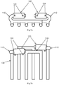
- the embodiment of the apparatus according to the invention shown in Fig. 4a, 4b and 4c comprises a forked heat tube assembly 100 attached to a side lining block 11.
- the forked heat tube assembly 100 comprises a manifold 150 from which a plurality of hot end heat tubes extend, representing the heat tube assembly hot end 130 or ends, and a heat tube assembly cold end 110 extending outside the manifold where a condensation unit 120 is provided.
- each hot end tube receives a substantially similar amount of working fluid in the liquid phase.
- the liquid is received directly from the manifold.
- the hot end tubes can be provided with an artery connecting the hot end tubes, preferably at a lower end. The technical effect of this is to even out the liquid level
- Fig. 4a shows an end view of a typical embodiment of a forked heat tube inserted into a side lining block
- Fig. 4b shows a front view of a typical embodiment of a forked heat tube inserted into a side lining block
- Fig. 4c shows a side view of a typical embodiment of a forked heat tube inserted into a side lining block
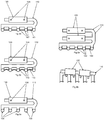
- the hot ends can further be provided by an artery 140 connecting adjacent hot end tubes as indicated by fig. 5a showing an end view of a forked heat tube provided with a substantially straight artery.
- the artery 140 can be provided with buckles as shown in fig. 5b.
- Fig. 5c shows an embodiment without an artery.
- Fig. 5d shows a front view of a forked heat tube provided with an artery connecting a plurality of hot ends between each heat tube.
- the artery is in-line and comprises a series of smaller tubes, each connecting the two adjacent hot end tubes.
- Fig. 5e shows side view of fig. 5d . Provisions must be made in the side lining block to accommodate the artery if the heat tubes are provided by hollows defined in the side lining block.
- Fig. 5f shows a detail of a connection of fig. 5d , showing how liquid can be transferred between individual tubes to equalise the liquid level. All hot end tubes except the outermost hot end tubes are directly connected to two neighbouring heat tubes which allows for fast draining or filling of liquid. The disadvantage is the complexity of fitting an in-line artery and the many connections made to the heat tubes.
- Fig. 5g shows a front view of a forked heat tube provided with an artery connecting a plurality of hot ends at the end of each heat tube.
- the artery 140 is a single tube connected to the hot end tubes using smaller connecting tubes called arterioles 144 that at one end are connected to the artery at an artery joint 142 and at the other end to the bottom of each respective hot end tube.
- Fig. 5h shows a side view of fig. 5g . Again provisions must be made in the side lining block to accommodate the artery if the heat tubes are provided by hollows defined in the side lining block.
- Fig. 5i shows a detail of a connection of fig. 2g , showing how liquid can be transferred between individual tubes to equalise the liquid level. All hot end tubes are connected to the artery, ensuring a more uniform filling than in the previous example where all adjustments will involve liquid transfer through possibly several hot end tubes and where the transfer rate would depend on the inclination with respect to gravity.
- Fig. 5j shows a front view of a forked heat tube provided with an artery connecting a plurality of hot ends at the side of each heat tube.
- the artery 140 is a single tube connected to the hot end tubes using smaller connecting tubes called arterioles 144 that at one end are connected to the artery at an artery joint 142 and at the other end to the side of the lower end 132 of each respective hot end tube.
- Fig. 5k shows a side view of fig. 2j . Provisions must be made in the side lining block to accommodate the artery if the heat tubes are provided by hollows defined in the side lining block unless the hollows are canals provided along the surface of the side lining and shallow compared to the position of the artery.
- Fig. 5j shows a front view of a forked heat tube provided with an artery connecting a plurality of hot ends at the side of each heat tube.
- the artery 140 is a single tube connected to the hot end tubes using smaller connecting tubes called arterioles 144 that at
- 5l shows a detail of a connection of fig. 2j , illustrating how liquid can be transferred between individual tubes to equalise the liquid level.
- All hot end tubes are connected to the artery, ensuring a more uniform filling than in the previous example where all adjustments will involve liquid transfer through possibly several hot end tubes and where the transfer rate would depend on the inclination with respect to gravity.
- the disadvantage is that the liquid level would have to extend to the level of the artery for liquid to overflow into the artery.
- Cooling of the cold end could be performed as in traditional solutions using a heat exchanger on the condensation end as already shown in fig 4 . Since fluid in the gas phase is collected from a plurality of hot end tubes by the manifold the amount of fluid to be condensed back to the liquid phase will be larger than for traditional heat tubes.
- An obvious solution is to provide the heat tube assembly with a large condensation unit.
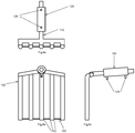
- the cold end having one condensation unit can be replaced by two cold ends having condensation units as shown in fig. 6a .
- This slight increase in complexity provides the advantage of increased reliability since the two heat exchanges can be connected to separate circuits and in the case of one circuit failing the other circuit will still be operating and thus allow for continuous operations.
- fig. 6a shows both cold ends being attached to the same side of the manifold one could also use both ends of the manifold.
- Fig. 6b shows a different high reliability configuration where one cold end is provided with two heat exchangers. Typically each heat exchanger is connected to different cooling circuits.
- Combinations with a plurality of heat exchangers on a plurality of cold ends attached to the same manifold are also possible.
- working fluid in the liquid phase evaporates along the length of the hot end tubes and flows as vapour towards the manifold where the vapour is collected by the manifold from all hot end tubes and brought into the cold end or ends.
- At the at least one cold end heat is removed by at least one condensation unit cooled typically by oil. This causes the working fluid in the vapour phase to condensate and flows as liquid towards the manifold where the liquid is distributed into the hot end tubes. It is preferred that the liquid flow is sufficient to allow liquid to reach the lower end of the heat tubes before evaporating again.
- An artery if present, enables redistribution of liquid between the hot end tubes should the filling rate of the hot end tubes differ significantly.
- vapour phase flow can exceed the speed of sound and reach a point where this flow sweeps liquid along the vapour flow and effectively reverses the normal liquid flow direction. This reduces the effective amount of working medium and thus also reduces the heat transport capacity.
- the flow rates must be adjusted accordingly, for instance by increasing the diameter of the tubing. This is particularly important for the manifold where the flow is the sum for a plurality of hot end tubes. Increasing the diameter is one solution, by reducing the maximum speed of the flow. Attaching cold ends to different positions along the manifold also reduces the maximum flow rate in the manifold.
- the oil used for cooling the heat exchangers transports heat out of the heat tube assembly and allows for recycling of heat, for instance by raising steam for use in a steam turbine.
- the circuits can be interleaved in such a way that if one circuit fails only a fraction of the forked heat tube assemblies stop working.
- a forked heat tube assembly can be provided with more than one heat exchanger which allows for continuous operations of all heat tube assemblies though at least some with limited capacity.
- thermoforming a manifold having a single heat tube representing a hot end and a plurality of condensers. This can be useful for high availability and reliability systems. While initially this embodiment appears compact and attractive it should be noted that it entails several complications such as the handling of coolant circuits inside the manifold.
- the heat tube is defined by an unbroken surface while this integrated solution requires penetration for entry and exit of the cooling medium.
- High reliability is important, as is the possibility of repairing and maintaining heat tube assemblies during operation of a cell and also the ability to avoid single points of failure in order to withstand limited problems without catastrophic failure of the operations.
- a solution is envisaged using interleaved forked heat assemblies wherein hot ends of a first forked heat tube assembly is interleaved with hot ends of a second forked heat tube assembly. The effect of this is that in the case of a failure of one forked heat tube assembly the other forked heat tube assembly is able to take the workload and maintain the protective side layer.
- Fig. 7a shows an end view of a typical embodiment of two interleaved forked heat tubes, showing how a first, third and fifth hot end tube are connected to a first manifold and a second, fourth and sixth hot end tube are connected to a second manifold.
- Fig 7b shows the embodiment in a front view.
- the individual heat tube assemblies are asymmetrical in terms of length of the hot end tubes and in the connection of the cold ends to the respective manifolds. Using centre fed cold ends will improve symmetry and possibly make the two heat tube assemblies fully interchangeable, reducing cost relating to manufacture and inventory. A 3-way and higher order interleaving is also possible.
- Interleaved solutions can also be provided with arteries.
- the arteries are in different planes, for instance a first forked heat tube assembly can be provided with an in-line or end mounted artery as shown in fig. 5d and 5f respectively, and a second forked heat tube assembly can be provided with a side mounted artery as shown in fig. 5j .
- Fig. 8b shows a front view of an embodiment of a forked heat tube with a centre fed cold end.
- This has the advantage of reducing the flow speed in the two side branches of the manifold. A slight incline with respect to gravity is shown for the manifold; one way of ensuring working fluid in the liquid form is evenly distributed.
- the cold end projects out in the direction away from the side lining block, which has the further advantage of simplifying the structure compared to previously shown embodiments where an extra bend in the cold end is indicated. Modifying the previous embodiments with outward projecting cold ends is also a possibility.
- the condensation takes place at a cold end external to the manifold.
- the inventors have realised that these functions could be combined, at the cost of added complexity relating to the need to penetrate the heat tube assembly for feed through for the oil used in the cooling, which goes against the traditional teaching of heat tube design.
- Fig. 9a shows an end view of an embodiment of a forked heat tube with a condenser integrated in a manifold having two feed through fitted with a fluid connector 154, typically for oil.
- the heat exchanger inside can have many different surfaces such as a blade or wing profile. For the maximum efficiency it is important that the effective surface area is maximised, for instance by using a surface like cooling fins.
- An advantage of an integrated manifold is that it overcomes the problem of increase of flow speed in a manifold that aggregates the flow from each hot end tube and brings the total flow into one cold end. For an integrated manifold the flow speed can thus be kept low.
- the invention finds use in as aluminium electrolysis cell and exploitation of the heat. More specifically it can be used with an electrolysis cell comprising a system as described above.
Landscapes
- Chemical & Material Sciences (AREA)
- Engineering & Computer Science (AREA)
- Chemical Kinetics & Catalysis (AREA)
- Electrochemistry (AREA)
- Materials Engineering (AREA)
- Metallurgy (AREA)
- Organic Chemistry (AREA)
- Heat-Exchange Devices With Radiators And Conduit Assemblies (AREA)
- Electrolytic Production Of Metals (AREA)
- Electrolytic Production Of Non-Metals, Compounds, Apparatuses Therefor (AREA)
Claims (16)
- System, das als gegabelte Wärmeleitungsbaugruppe bezeichnet wird, zum Steuern einer Schichtbildung in einer Aluminiumelektrolysezelle und zum Ausnutzen von Wärme, wobei die Elektrolysezelle eine Seitenverkleidung (11) und ein Gehäuse (8) umfasst;
dadurch gekennzeichnet, dass das System umfasst
zumindest eine wärmeendige Leitung zum Absorbieren von Wärme mittels Verdampfung eines Arbeitsfluids von einer Flüssigphase in eine Dampfphase;
zumindest ein kaltes Ende zum Kondensieren des Arbeitsfluids von einer Dampfphase zu einer Flüssigphase; und
einen Verteiler, von welchem aus sich die zumindest eine wärmeendige Leitung erstreckt; wobei der Verteiler das Arbeitsfluid zwischen dem zumindest einen warmen Ende und dem zumindest einen kalten Ende leitet. - System nach Anspruch 1, wobei die zumindest eine wärmeendige Leitung ein Wärmerohr ist.
- System nach Anspruch 1, wobei die zumindest eine wärmeendige Leitung ein Thermosiphon ist.
- System nach einem der Ansprüche 1-3, wobei das zumindest eine kalte Ende außerhalb des Verteilers ist.
- System nach einem der Ansprüche 1-3, wobei das zumindest eine kalte Ende innerhalb des Verteilers ist.
- System nach einem der Ansprüche 1-5, wobei das zumindest eine kalte Ende mit mehr als einem Wärmetauscher versehen ist.
- System nach einem der Ansprüche 1-6, ferner umfassend eine Arterie für eine gleichmäßige Verteilung des Arbeitsfluids in dem flüssigen Zustand an einem unteren Ende der zumindest einen wärmeendigen Leitung.
- System nach Anspruch 7, wobei die Arterie gekrümmt ist, um Flexibilität bereitzustellen.
- System nach Anspruch 7 oder 8, wobei die Arterie linear ausgebildet ist und eine Mehrzahl von kleineren Leitungen, die jeweils die zwei benachbarten wärmeendigen Leitungen verbinden, umfasst.
- System nach Anspruch 7 oder 8, wobei die Arterie eine einzige Leitung ist, die mit den wärmeendigen Leitungen unter Benutzung kleinerer Verbindungsleitungen verbunden ist, die als Arteriolen 144 bezeichnet werden, die an einem Ende mit der Arterie an einer Arterienverbindung 142 und an dem anderen Ende mit jeweils einer entsprechenden wärmeendigen Leitung verbunden sind.
- System nach Anspruch 10, wobei die Arteriolen an der Unterseite jeder entsprechenden wärmeendigen Leitung befestigt sind.
- System nach Anspruch 10, wobei die Arteriolen an der Seite jeder entsprechenden wärmeendigen Leitung befestigt sind.
- Verfahren zum Benutzen einer Vielzahl von Systemen nach Anspruch 6, wobei die Wärmetauscher mit einer Vielzahl von Kühlkreisläufen verbunden sind.
- Verfahren zum Benutzen einer Vielzahl von Systemen nach einem der Ansprüche 1-10, wobei heiße Enden einer ersten gegabelten Wärmeleitungsbaugruppe und heißen Enden einer zweiten gegabelten Wärmeleitungsbaugruppe ineinander verschränkt sind.
- Verfahren zum Steuern einer Schichtbildung in einer Aluminiumelektrolysezelle, gekennzeichnet durch ein Wegleiten der Wärme unter Benutzung der gegabelten Wärmeleitungsbaugruppe nach Anspruch 1.
- Elektrolysezelle umfassend eine Wärmeleitungsbaugruppe nach einem der Ansprüche 1-12.
Applications Claiming Priority (2)
| Application Number | Priority Date | Filing Date | Title |
|---|---|---|---|
| NO20120031A NO336846B1 (no) | 2012-01-12 | 2012-01-12 | Forgrenet varmerør |
| PCT/NO2013/050008 WO2013105867A1 (en) | 2012-01-12 | 2013-01-11 | Aluminium electrolysis cell comprising sidewall temperature control system |
Publications (3)
| Publication Number | Publication Date |
|---|---|
| EP2802686A1 EP2802686A1 (de) | 2014-11-19 |
| EP2802686A4 EP2802686A4 (de) | 2015-08-26 |
| EP2802686B1 true EP2802686B1 (de) | 2017-03-22 |
Family
ID=48781721
Family Applications (1)
| Application Number | Title | Priority Date | Filing Date |
|---|---|---|---|
| EP13736212.5A Not-in-force EP2802686B1 (de) | 2012-01-12 | 2013-01-11 | Aluminiumelektrolysezelle mit seitenwandtemperaturregelungssystem |
Country Status (8)
| Country | Link |
|---|---|
| US (1) | US20140332400A1 (de) |
| EP (1) | EP2802686B1 (de) |
| AR (1) | AR089712A1 (de) |
| CA (1) | CA2860967A1 (de) |
| EA (1) | EA201491188A1 (de) |
| NO (1) | NO336846B1 (de) |
| WO (1) | WO2013105867A1 (de) |
| ZA (1) | ZA201404672B (de) |
Families Citing this family (7)
| Publication number | Priority date | Publication date | Assignee | Title |
|---|---|---|---|---|
| NO337186B1 (no) * | 2013-05-06 | 2016-02-08 | Goodtech Recovery Tech As | Varmerørsammenstilling med returlinjer |
| NO341387B1 (en) * | 2015-04-24 | 2017-10-30 | Goodtech Recovery Tech As | Heat Tube With Channel Structure |
| NO340554B1 (en) * | 2015-05-18 | 2017-05-08 | Goodtech Recovery Tech As | Heat recovery |
| GB2564456A (en) * | 2017-07-12 | 2019-01-16 | Dubai Aluminium Pjsc | Electrolysis cell for Hall-Héroult process, with cooling pipes for forced air cooling |
| NO20180376A1 (en) | 2018-03-16 | 2019-09-17 | Cronus Tech As | A system for recovery of waste heat from an industrial plant |
| CN112210793B (zh) * | 2020-10-19 | 2022-06-10 | 郑州轻冶科技股份有限公司 | 一种侧部带热管换热器的铝电解槽 |
| CN116734648B (zh) * | 2023-06-14 | 2025-02-11 | 郑州轻冶科技股份有限公司 | 一种电解槽余热回收装置及电解槽 |
Family Cites Families (9)
| Publication number | Priority date | Publication date | Assignee | Title |
|---|---|---|---|---|
| GB2076428B (en) * | 1980-05-19 | 1983-11-09 | Carblox Ltd | Aluminium manufacture |
| DE3033710A1 (de) * | 1980-09-02 | 1982-04-01 | Schweizerische Aluminium AG, 3965 Chippis | Vorrichtung zum regulieren des waermeflusses einer aluminiumschmelzflusselektrolysezelle und verfahren zum betrieb dieser zelle |
| NO158511C (no) * | 1985-07-09 | 1988-09-21 | Invendt A S H | Anordning ved ovn l, saerliga luminium-elektrolyse. |
| NO313462B1 (no) * | 2000-06-07 | 2002-10-07 | Elkem Materials | Elektrolysecelle for fremstilling av aluminium, en rekke elektrolyseceller i en elektrolysehall, fremgangsmåte for åopprettholde en kruste på en sidevegg i en elektrolysecelle samtfremgangsmåte for gjenvinning av elektrisk energi fra en elektr |
| NO318012B1 (no) * | 2003-03-17 | 2005-01-17 | Norsk Hydro As | Strukturelle elementer for benyttelse i en elektrolysecelle |
| EP1805349B1 (de) * | 2004-10-21 | 2012-12-26 | BHP Billiton Innovation Pty Ltd | Interne kühlung einer elektrolytischen schmelzzelle |
| FR2893329B1 (fr) * | 2005-11-14 | 2008-05-16 | Aluminium Pechiney Soc Par Act | Cuve d'electrolyse avec echangeur thermique. |
| US20080020265A1 (en) * | 2006-07-24 | 2008-01-24 | Alcoa Inc. | Sidewall temperature control systems and methods and improved electrolysis cells relating to same |
| NO337977B1 (no) * | 2008-10-31 | 2016-07-18 | Norsk Hydro As | Fremgangsmåte og anordning for ekstrahering av varme fra aluminium elektrolyseceller |
-
2012
- 2012-01-12 NO NO20120031A patent/NO336846B1/no not_active IP Right Cessation
-
2013
- 2013-01-11 AR ARP130100101A patent/AR089712A1/es unknown
- 2013-01-11 US US14/365,455 patent/US20140332400A1/en not_active Abandoned
- 2013-01-11 WO PCT/NO2013/050008 patent/WO2013105867A1/en not_active Ceased
- 2013-01-11 CA CA2860967A patent/CA2860967A1/en not_active Abandoned
- 2013-01-11 EA EA201491188A patent/EA201491188A1/ru unknown
- 2013-01-11 EP EP13736212.5A patent/EP2802686B1/de not_active Not-in-force
-
2014
- 2014-06-25 ZA ZA2014/04672A patent/ZA201404672B/en unknown
Non-Patent Citations (1)
| Title |
|---|
| None * |
Also Published As
| Publication number | Publication date |
|---|---|
| WO2013105867A1 (en) | 2013-07-18 |
| EP2802686A4 (de) | 2015-08-26 |
| EP2802686A1 (de) | 2014-11-19 |
| NO336846B1 (no) | 2015-11-16 |
| ZA201404672B (en) | 2015-12-23 |
| US20140332400A1 (en) | 2014-11-13 |
| EA201491188A1 (ru) | 2014-12-30 |
| CA2860967A1 (en) | 2013-07-18 |
| AR089712A1 (es) | 2014-09-10 |
| NO20120031A1 (no) | 2013-07-15 |
Similar Documents
| Publication | Publication Date | Title |
|---|---|---|
| EP2802686B1 (de) | Aluminiumelektrolysezelle mit seitenwandtemperaturregelungssystem | |
| AU2009310492B2 (en) | Method and means for extracting heat from aluminium electrolysis cells | |
| US4749463A (en) | Electrometallurgical cell arrangement | |
| EP2619518A1 (de) | System und verfahren zur steuerung der seitenschichtbildung in einer aluminiumelektrolysezelle | |
| EP2766517B1 (de) | System und verfahren zur steuerung der schichtbildung bei einer aluminiumelektrolysezelle | |
| CN113913873B (zh) | 一种可充当柔性负载的铝电解槽及其热平衡控制方法 | |
| EP2994557B1 (de) | Aluminiumelektrolysezelle mit seitenwandtemperaturregelungssystem | |
| EP3468030A1 (de) | Thermoelektrische stromerzeugungsvorrichtung und thermoelektrisches stromerzeugungssystem | |
| He et al. | Experimental study on heat transfer performance of micro-grooved I-shaped aluminum heat pipe for heat pipe heat exchangers | |
| CN120667958A (zh) | 一种用于双导热高温热管 | |
| EP2766516B1 (de) | System und verfahren zur steuerung der schichtbildung in einer aluminiumelektrolysezelle | |
| CN120452886B (zh) | 导电散热一体化线缆及方法 | |
| CN112968231A (zh) | 电池包 | |
| CN113346830B (zh) | 一种复合液态金属和泡沫金属的光伏瓦散热器 | |
| CN111649610B (zh) | 多孔介质换热装置及系统 | |
| Yin et al. | Experimental study on thermal performance enhancement of a PCM-based energy storage unit integrated with sintered-wick heat conductor | |
| CN121163284A (zh) | 一种储热器 | |
| CN102242989A (zh) | 串联式铝合金翅片排管蒸发器 | |
| KR20070092016A (ko) | 연료전지 시스템용 열교환기 | |
| Li et al. | Performance Comparison of Novel Topology-Optimized and Heat-Targeting Flat-Plate Oscillating Heat Pipes as Heat Spreaders for Cooling of Multi-Heat Source Electronics |
Legal Events
| Date | Code | Title | Description |
|---|---|---|---|
| PUAI | Public reference made under article 153(3) epc to a published international application that has entered the european phase |
Free format text: ORIGINAL CODE: 0009012 |
|
| 17P | Request for examination filed |
Effective date: 20140812 |
|
| AK | Designated contracting states |
Kind code of ref document: A1 Designated state(s): AL AT BE BG CH CY CZ DE DK EE ES FI FR GB GR HR HU IE IS IT LI LT LU LV MC MK MT NL NO PL PT RO RS SE SI SK SM TR |
|
| DAX | Request for extension of the european patent (deleted) | ||
| RA4 | Supplementary search report drawn up and despatched (corrected) |
Effective date: 20150724 |
|
| RIC1 | Information provided on ipc code assigned before grant |
Ipc: C25C 3/08 20060101AFI20150720BHEP |
|
| GRAP | Despatch of communication of intention to grant a patent |
Free format text: ORIGINAL CODE: EPIDOSNIGR1 |
|
| INTG | Intention to grant announced |
Effective date: 20161013 |
|
| STAA | Information on the status of an ep patent application or granted ep patent |
Free format text: STATUS: GRANT OF PATENT IS INTENDED |
|
| GRAS | Grant fee paid |
Free format text: ORIGINAL CODE: EPIDOSNIGR3 |
|
| GRAA | (expected) grant |
Free format text: ORIGINAL CODE: 0009210 |
|
| STAA | Information on the status of an ep patent application or granted ep patent |
Free format text: STATUS: THE PATENT HAS BEEN GRANTED |
|
| AK | Designated contracting states |
Kind code of ref document: B1 Designated state(s): AL AT BE BG CH CY CZ DE DK EE ES FI FR GB GR HR HU IE IS IT LI LT LU LV MC MK MT NL NO PL PT RO RS SE SI SK SM TR |
|
| REG | Reference to a national code |
Ref country code: GB Ref legal event code: FG4D |
|
| REG | Reference to a national code |
Ref country code: CH Ref legal event code: EP |
|
| REG | Reference to a national code |
Ref country code: AT Ref legal event code: REF Ref document number: 877869 Country of ref document: AT Kind code of ref document: T Effective date: 20170415 |
|
| REG | Reference to a national code |
Ref country code: IE Ref legal event code: FG4D |
|
| REG | Reference to a national code |
Ref country code: DE Ref legal event code: R096 Ref document number: 602013018893 Country of ref document: DE |
|
| REG | Reference to a national code |
Ref country code: NL Ref legal event code: MP Effective date: 20170322 |
|
| PG25 | Lapsed in a contracting state [announced via postgrant information from national office to epo] |
Ref country code: LT Free format text: LAPSE BECAUSE OF FAILURE TO SUBMIT A TRANSLATION OF THE DESCRIPTION OR TO PAY THE FEE WITHIN THE PRESCRIBED TIME-LIMIT Effective date: 20170322 Ref country code: GR Free format text: LAPSE BECAUSE OF FAILURE TO SUBMIT A TRANSLATION OF THE DESCRIPTION OR TO PAY THE FEE WITHIN THE PRESCRIBED TIME-LIMIT Effective date: 20170623 Ref country code: HR Free format text: LAPSE BECAUSE OF FAILURE TO SUBMIT A TRANSLATION OF THE DESCRIPTION OR TO PAY THE FEE WITHIN THE PRESCRIBED TIME-LIMIT Effective date: 20170322 Ref country code: FI Free format text: LAPSE BECAUSE OF FAILURE TO SUBMIT A TRANSLATION OF THE DESCRIPTION OR TO PAY THE FEE WITHIN THE PRESCRIBED TIME-LIMIT Effective date: 20170322 Ref country code: NO Free format text: LAPSE BECAUSE OF FAILURE TO SUBMIT A TRANSLATION OF THE DESCRIPTION OR TO PAY THE FEE WITHIN THE PRESCRIBED TIME-LIMIT Effective date: 20170622 |
|
| REG | Reference to a national code |
Ref country code: LT Ref legal event code: MG4D |
|
| REG | Reference to a national code |
Ref country code: AT Ref legal event code: MK05 Ref document number: 877869 Country of ref document: AT Kind code of ref document: T Effective date: 20170322 |
|
| PG25 | Lapsed in a contracting state [announced via postgrant information from national office to epo] |
Ref country code: SE Free format text: LAPSE BECAUSE OF FAILURE TO SUBMIT A TRANSLATION OF THE DESCRIPTION OR TO PAY THE FEE WITHIN THE PRESCRIBED TIME-LIMIT Effective date: 20170322 Ref country code: BG Free format text: LAPSE BECAUSE OF FAILURE TO SUBMIT A TRANSLATION OF THE DESCRIPTION OR TO PAY THE FEE WITHIN THE PRESCRIBED TIME-LIMIT Effective date: 20170622 Ref country code: LV Free format text: LAPSE BECAUSE OF FAILURE TO SUBMIT A TRANSLATION OF THE DESCRIPTION OR TO PAY THE FEE WITHIN THE PRESCRIBED TIME-LIMIT Effective date: 20170322 Ref country code: RS Free format text: LAPSE BECAUSE OF FAILURE TO SUBMIT A TRANSLATION OF THE DESCRIPTION OR TO PAY THE FEE WITHIN THE PRESCRIBED TIME-LIMIT Effective date: 20170322 |
|
| PG25 | Lapsed in a contracting state [announced via postgrant information from national office to epo] |
Ref country code: NL Free format text: LAPSE BECAUSE OF FAILURE TO SUBMIT A TRANSLATION OF THE DESCRIPTION OR TO PAY THE FEE WITHIN THE PRESCRIBED TIME-LIMIT Effective date: 20170322 |
|
| PG25 | Lapsed in a contracting state [announced via postgrant information from national office to epo] |
Ref country code: CZ Free format text: LAPSE BECAUSE OF FAILURE TO SUBMIT A TRANSLATION OF THE DESCRIPTION OR TO PAY THE FEE WITHIN THE PRESCRIBED TIME-LIMIT Effective date: 20170322 Ref country code: RO Free format text: LAPSE BECAUSE OF FAILURE TO SUBMIT A TRANSLATION OF THE DESCRIPTION OR TO PAY THE FEE WITHIN THE PRESCRIBED TIME-LIMIT Effective date: 20170322 Ref country code: AT Free format text: LAPSE BECAUSE OF FAILURE TO SUBMIT A TRANSLATION OF THE DESCRIPTION OR TO PAY THE FEE WITHIN THE PRESCRIBED TIME-LIMIT Effective date: 20170322 Ref country code: SK Free format text: LAPSE BECAUSE OF FAILURE TO SUBMIT A TRANSLATION OF THE DESCRIPTION OR TO PAY THE FEE WITHIN THE PRESCRIBED TIME-LIMIT Effective date: 20170322 Ref country code: EE Free format text: LAPSE BECAUSE OF FAILURE TO SUBMIT A TRANSLATION OF THE DESCRIPTION OR TO PAY THE FEE WITHIN THE PRESCRIBED TIME-LIMIT Effective date: 20170322 |
|
| PG25 | Lapsed in a contracting state [announced via postgrant information from national office to epo] |
Ref country code: SM Free format text: LAPSE BECAUSE OF FAILURE TO SUBMIT A TRANSLATION OF THE DESCRIPTION OR TO PAY THE FEE WITHIN THE PRESCRIBED TIME-LIMIT Effective date: 20170322 Ref country code: PL Free format text: LAPSE BECAUSE OF FAILURE TO SUBMIT A TRANSLATION OF THE DESCRIPTION OR TO PAY THE FEE WITHIN THE PRESCRIBED TIME-LIMIT Effective date: 20170322 Ref country code: IS Free format text: LAPSE BECAUSE OF FAILURE TO SUBMIT A TRANSLATION OF THE DESCRIPTION OR TO PAY THE FEE WITHIN THE PRESCRIBED TIME-LIMIT Effective date: 20170722 Ref country code: PT Free format text: LAPSE BECAUSE OF FAILURE TO SUBMIT A TRANSLATION OF THE DESCRIPTION OR TO PAY THE FEE WITHIN THE PRESCRIBED TIME-LIMIT Effective date: 20170724 |
|
| REG | Reference to a national code |
Ref country code: DE Ref legal event code: R097 Ref document number: 602013018893 Country of ref document: DE |
|
| PLBE | No opposition filed within time limit |
Free format text: ORIGINAL CODE: 0009261 |
|
| STAA | Information on the status of an ep patent application or granted ep patent |
Free format text: STATUS: NO OPPOSITION FILED WITHIN TIME LIMIT |
|
| PG25 | Lapsed in a contracting state [announced via postgrant information from national office to epo] |
Ref country code: DK Free format text: LAPSE BECAUSE OF FAILURE TO SUBMIT A TRANSLATION OF THE DESCRIPTION OR TO PAY THE FEE WITHIN THE PRESCRIBED TIME-LIMIT Effective date: 20170322 |
|
| 26N | No opposition filed |
Effective date: 20180102 |
|
| PG25 | Lapsed in a contracting state [announced via postgrant information from national office to epo] |
Ref country code: IT Free format text: LAPSE BECAUSE OF FAILURE TO SUBMIT A TRANSLATION OF THE DESCRIPTION OR TO PAY THE FEE WITHIN THE PRESCRIBED TIME-LIMIT Effective date: 20170322 Ref country code: SI Free format text: LAPSE BECAUSE OF FAILURE TO SUBMIT A TRANSLATION OF THE DESCRIPTION OR TO PAY THE FEE WITHIN THE PRESCRIBED TIME-LIMIT Effective date: 20170322 |
|
| REG | Reference to a national code |
Ref country code: DE Ref legal event code: R119 Ref document number: 602013018893 Country of ref document: DE |
|
| REG | Reference to a national code |
Ref country code: CH Ref legal event code: PL |
|
| GBPC | Gb: european patent ceased through non-payment of renewal fee |
Effective date: 20180111 |
|
| PG25 | Lapsed in a contracting state [announced via postgrant information from national office to epo] |
Ref country code: DE Free format text: LAPSE BECAUSE OF NON-PAYMENT OF DUE FEES Effective date: 20180801 Ref country code: FR Free format text: LAPSE BECAUSE OF NON-PAYMENT OF DUE FEES Effective date: 20180131 Ref country code: LU Free format text: LAPSE BECAUSE OF NON-PAYMENT OF DUE FEES Effective date: 20180111 |
|
| REG | Reference to a national code |
Ref country code: IE Ref legal event code: MM4A |
|
| REG | Reference to a national code |
Ref country code: FR Ref legal event code: ST Effective date: 20180928 |
|
| REG | Reference to a national code |
Ref country code: BE Ref legal event code: MM Effective date: 20180131 |
|
| PG25 | Lapsed in a contracting state [announced via postgrant information from national office to epo] |
Ref country code: GB Free format text: LAPSE BECAUSE OF NON-PAYMENT OF DUE FEES Effective date: 20180111 Ref country code: LI Free format text: LAPSE BECAUSE OF NON-PAYMENT OF DUE FEES Effective date: 20180131 Ref country code: BE Free format text: LAPSE BECAUSE OF NON-PAYMENT OF DUE FEES Effective date: 20180131 Ref country code: CH Free format text: LAPSE BECAUSE OF NON-PAYMENT OF DUE FEES Effective date: 20180131 |
|
| PG25 | Lapsed in a contracting state [announced via postgrant information from national office to epo] |
Ref country code: IE Free format text: LAPSE BECAUSE OF NON-PAYMENT OF DUE FEES Effective date: 20180111 |
|
| PG25 | Lapsed in a contracting state [announced via postgrant information from national office to epo] |
Ref country code: MC Free format text: LAPSE BECAUSE OF FAILURE TO SUBMIT A TRANSLATION OF THE DESCRIPTION OR TO PAY THE FEE WITHIN THE PRESCRIBED TIME-LIMIT Effective date: 20170322 |
|
| PG25 | Lapsed in a contracting state [announced via postgrant information from national office to epo] |
Ref country code: ES Free format text: LAPSE BECAUSE OF FAILURE TO SUBMIT A TRANSLATION OF THE DESCRIPTION OR TO PAY THE FEE WITHIN THE PRESCRIBED TIME-LIMIT Effective date: 20170322 |
|
| PG25 | Lapsed in a contracting state [announced via postgrant information from national office to epo] |
Ref country code: MT Free format text: LAPSE BECAUSE OF NON-PAYMENT OF DUE FEES Effective date: 20180111 |
|
| PG25 | Lapsed in a contracting state [announced via postgrant information from national office to epo] |
Ref country code: TR Free format text: LAPSE BECAUSE OF FAILURE TO SUBMIT A TRANSLATION OF THE DESCRIPTION OR TO PAY THE FEE WITHIN THE PRESCRIBED TIME-LIMIT Effective date: 20170322 |
|
| PG25 | Lapsed in a contracting state [announced via postgrant information from national office to epo] |
Ref country code: HU Free format text: LAPSE BECAUSE OF FAILURE TO SUBMIT A TRANSLATION OF THE DESCRIPTION OR TO PAY THE FEE WITHIN THE PRESCRIBED TIME-LIMIT; INVALID AB INITIO Effective date: 20130111 |
|
| PG25 | Lapsed in a contracting state [announced via postgrant information from national office to epo] |
Ref country code: MK Free format text: LAPSE BECAUSE OF NON-PAYMENT OF DUE FEES Effective date: 20170322 Ref country code: CY Free format text: LAPSE BECAUSE OF FAILURE TO SUBMIT A TRANSLATION OF THE DESCRIPTION OR TO PAY THE FEE WITHIN THE PRESCRIBED TIME-LIMIT Effective date: 20170322 |
|
| PG25 | Lapsed in a contracting state [announced via postgrant information from national office to epo] |
Ref country code: AL Free format text: LAPSE BECAUSE OF FAILURE TO SUBMIT A TRANSLATION OF THE DESCRIPTION OR TO PAY THE FEE WITHIN THE PRESCRIBED TIME-LIMIT Effective date: 20170322 |