EP2801919A1 - Mobiles Endgerät und Steuerungsverfahren dafür - Google Patents
Mobiles Endgerät und Steuerungsverfahren dafür Download PDFInfo
- Publication number
- EP2801919A1 EP2801919A1 EP14167566.0A EP14167566A EP2801919A1 EP 2801919 A1 EP2801919 A1 EP 2801919A1 EP 14167566 A EP14167566 A EP 14167566A EP 2801919 A1 EP2801919 A1 EP 2801919A1
- Authority
- EP
- European Patent Office
- Prior art keywords
- video
- controller
- mobile terminal
- period
- thumbnail
- Prior art date
- Legal status (The legal status is an assumption and is not a legal conclusion. Google has not performed a legal analysis and makes no representation as to the accuracy of the status listed.)
- Ceased
Links
Images


Classifications
-
- G—PHYSICS
- G11—INFORMATION STORAGE
- G11B—INFORMATION STORAGE BASED ON RELATIVE MOVEMENT BETWEEN RECORD CARRIER AND TRANSDUCER
- G11B27/00—Editing; Indexing; Addressing; Timing or synchronising; Monitoring; Measuring tape travel
- G11B27/10—Indexing; Addressing; Timing or synchronising; Measuring tape travel
- G11B27/19—Indexing; Addressing; Timing or synchronising; Measuring tape travel by using information detectable on the record carrier
- G11B27/28—Indexing; Addressing; Timing or synchronising; Measuring tape travel by using information detectable on the record carrier by using information signals recorded by the same method as the main recording
-
- G—PHYSICS
- G06—COMPUTING; CALCULATING OR COUNTING
- G06F—ELECTRIC DIGITAL DATA PROCESSING
- G06F16/00—Information retrieval; Database structures therefor; File system structures therefor
- G06F16/70—Information retrieval; Database structures therefor; File system structures therefor of video data
- G06F16/73—Querying
- G06F16/738—Presentation of query results
- G06F16/739—Presentation of query results in form of a video summary, e.g. the video summary being a video sequence, a composite still image or having synthesized frames
Definitions
- the present invention relates to a mobile terminal that is capable of creating a thumbnail including a plurality of representative images and a controlling method thereof.
- a mobile terminal is a device which may be configured to perform various functions. Examples of such functions include data and voice communications, capturing images and video via a camera, recording audio, playing music files and outputting music via a speaker system, and displaying images and video on a display.
- terminals can be classified into mobile terminals and stationary terminals according to a presence or non-presence of mobility. And, the mobile terminals can be further classified into handheld terminals and vehicle mount terminals according to availability for hand-carry.
- Viewing video or photographs on a mobile terminal is one of the popularized functions.
- multimedia files such as video or images
- thumbnails are displayed together with file names when video or images are displayed for user convenience in searching. Since an image is a still image, there is no problem in recognizing contents of the image only using a thumbnail. Since video includes a plurality of successive frames, however, there is problem in recognizing contents of the video only using a thumbnail.
- embodiments of the present invention are directed to a mobile terminal and controlling method thereof that substantially obviate one or more problems due to limitations and disadvantages of the related art.
- the present invention has been made in view of the above problems, and it is an object of the present invention to provide a mobile terminal and a controlling method therefore with improved user convenience.
- a mobile terminal includes a memory for storing video, a display for outputting the video and a thumbnail of the video, and a controller for playing the video and creating a plurality of representative images from the video to create the thumbnail.
- the controller may combine the representative images to create the thumbnail.
- a controlling method of a mobile terminal includes creating a plurality of representative images from video and combining the representative images to create a thumbnail of the video and displaying the created thumbnail.
- the controlling method according to the present invention may be performed by a controller of the mobile terminal of the present invention, i.e. the mobile terminal according to the present invention is configured to perform the controlling method according to the present invention.
- At least one of the representative images is created based on at least one frame extracted from each divided period in a case in which a whole period of the video is divided into a plurality of periods.
- the remaining period may refer to a period remaining after a part of the video has been viewed.
- At least one of the representative images is created based on at least one frame extracted from a highlight period of the video.
- the controller may be configured to set a highlight period considering at least one selected from among movement speed of a subject recorded in the video, intensity of a sound recorded in the video, and brightness of each frame of the video.
- At least one of the representative images is created based on at least one frame extracted from a period of the video in which a predetermined character appears.
- At least one of the representative images is created based on at least one frame extracted from a period of the video in which the other party who becomes a target of an event which has been generated recently is recorded.
- the event may comprise at least one selected from among reception and/or transmission of a telephone call, transmission and/or reception of a message, and transmission and/or reception of information through a social network service (SNS).
- SNS social network service
- At least one of the representative images may be created based on the converted text.
- At least one of the representative images is created based on at least one frame extracted from a period of the video in which a character in a photograph related to the video is recorded.
- the controller (180) may be configured to determine at least one selected from between a photograph taken at the same date as in the video and a photograph taken at the same place as in the video as the photograph related to the video.
- At least one of the representative images is created based on at least one frame extracted from a period of the video in which a character or a thing indicated by a keyword input by a user is recorded.
- the keyword may include one that the user has used during a preceding or latest web search.
- the thumbnail comprises a video playing region and a representative image region.
- the controller (180) may be configured to play the video from a beginning and/or to resume playing of the video from a time when the latest playing of the video has been finished.
- the controller (180) may be configured to play the video from a playing time corresponding to one of the representative images selected by the touch.
- the controller (180) may control the video to be played only during a period represented by one of the representative images selected by the touch.
- the controller (180) may be configured to control a popup window for performing communication with a character corresponding to one of the representative images selected by the touch to be output.
- the suffixes 'module', 'unit' and 'part' are used for elements in order to facilitate the disclosure only. Therefore, significant meanings or roles are not given to the suffixes themselves and it is understood that the 'module', 'unit' and 'part' can be used together or interchangeably.
- the present invention can be applicable to a various types of mobile terminals.
- mobile terminals include mobile phones, user equipments, smart phones, digital broadcast receivers, personal digital assistants, laptop computers, portable multimedia players (PMP), navigators and the like.
- PMP portable multimedia players
- Fig. 1 is a block diagram of a mobile terminal 100 in accordance with an embodiment of the present invention.
- Fig. 1 shows the mobile terminal 100 according to one embodiment of the present invention includes a wireless communication unit 110, an A/V (audio/video) input unit 120, a user input unit 130, a sensing unit 140, an output unit 150, a memory 160, an interface unit 170, a controller 180, a power supply unit 190 and the like.
- FIG. 1 shows the mobile terminal 100 having various components, but it is understood that implementing all of the illustrated components is not a requirement. Greater or fewer components may alternatively be implemented.
- the wireless communication unit 110 typically includes one or more components which permits wireless communication between the mobile terminal 100 and a wireless communication system or network within which the mobile terminal 100 is located.
- the wireless communication unit 110 can include a broadcast receiving module 111, a mobile communication module 112, a wireless internet module 113, a short-range communication module 114, a position-location module 115 and the like.
- the broadcast receiving module 111 receives a broadcast signal and/or broadcast associated information from an external broadcast managing server via a broadcast channel.
- the broadcast channel may include a satellite channel and a terrestrial channel.
- At least two broadcast receiving modules 111 can be provided to the mobile terminal 100 in pursuit of simultaneous receptions of at least two broadcast channels or broadcast channel switching facilitation.
- the broadcast managing server generally refers to a server which generates and transmits a broadcast signal and/or broadcast associated information or a server which is provided with a previously generated broadcast signal and/or broadcast associated information and then transmits the provided signal or information to a terminal.
- the broadcast signal may be implemented as a TV broadcast signal, a radio broadcast signal, and a data broadcast signal, among others. If desired, the broadcast signal may further include a broadcast signal combined with a TV or radio broadcast signal.
- the broadcast associated information includes information associated with a broadcast channel, a broadcast program, a broadcast service provider, etc. And, the broadcast associated information can be provided via a mobile communication network. In this case, the broadcast associated information can be received by the mobile communication module 112.
- broadcast associated information can be implemented in various forms.
- broadcast associated information may include an electronic program guide (EPG) of digital multimedia broadcasting (DMB) and electronic service guide (ESG) of digital video broadcast-handheld (DVB-H).
- EPG electronic program guide
- ESG electronic service guide
- DMB digital multimedia broadcasting
- DVB-H digital video broadcast-handheld
- the broadcast receiving module 111 may be configured to receive broadcast signals transmitted from various types of broadcast systems.
- broadcasting systems include digital multimedia broadcasting-terrestrial (DMB-T), digital multimedia broadcasting-satellite (DMB-S), digital video broadcast-handheld (DVB-H), Convergence of Broadcasting and Mobile Service(DVB-CBMS), Open Mobile Alliance-BroadCAST(OMA-BCAST), China Multimedia Mobile Broadcasting (CMMB), Mobile Broadcasting Business Management System(MBBMS), the data broadcasting system known as media forward link only (MediaFLO®) and integrated services digital broadcastterrestrial (ISDB-T).
- the broadcast receiving module 111 can be configured suitable for other broadcasting systems as well as the above-explained digital broadcasting systems.
- the broadcast signal and/or broadcast associated information received by the broadcast receiving module 111 may be stored in a suitable device, such as a memory 160.
- the mobile communication module 112 transmits/receives wireless signals to/from one or more network entities (e.g., base station, external terminal, server, etc.) via a mobile network such as GSM (Global System for Mobile communications), CDMA (Code Division Multiple Access), WCDMA (Wideband CDMA) and so on.
- a mobile network such as GSM (Global System for Mobile communications), CDMA (Code Division Multiple Access), WCDMA (Wideband CDMA) and so on.
- GSM Global System for Mobile communications
- CDMA Code Division Multiple Access
- WCDMA Wideband CDMA
- the wireless internet module 113 supports Internet access for the mobile terminal 100.
- This module may be internally or externally coupled to the mobile terminal 100.
- the wireless Internet technology can include WLAN(Wireless LAN) (Wi-Fi), WIBRO (Wireless broadband), WIMAX(World Interoperability for Microwave Access), HSDPA(High Speed Downlink Packet Access), GSM, CDMA, WCDMA, LTE (Long Term Evolution) etc.
- Wireless internet access by WIBRO, HSPDA, GSM, CDMA, WCDMA, LTE or the like is achieved via a mobile communication network.
- the wireless internet module 113 configured to perform the wireless internet access via the mobile communication network can be understood as a sort of the mobile communication module 112.
- the short-range communication module 114 facilitates relatively short-range communications. Suitable technologies for implementing this module include radio frequency identification (RFID), infrared data association (IrDA), ultra-wideband (UWB), as well at the networking technologies commonly referred to as Bluetooth and ZigBee, to name a few.
- RFID radio frequency identification
- IrDA infrared data association
- UWB ultra-wideband
- the position-location module 115 identifies or otherwise obtains the location of the mobile terminal 100. If desired, this module may be implemented with a global positioning system (GPS) module. According to the current technology, the GPS module 115 is able to precisely calculate current 3-dimensional position information based on at least one of longitude, latitude and altitude and direction (or orientation) by calculating distance information and precise time information from at least three satellites and then applying triangulation to the calculated information. Currently, location and time informations are calculated using three satellites, and errors of the calculated location position and time informations are then amended using another satellite. Besides, the GPS module 115 is able to calculate speed information by continuously calculating a real-time current location.
- GPS global positioning system
- the audio/video (A/V) input unit 120 is configured to provide audio or video signal input to the mobile terminal 100.
- the A/V input unit 120 includes a camera 121 and a microphone 122.
- the camera 121 receives and processes image frames of still pictures or video, which are obtained by an image sensor in a video call mode or a photographing mode. And, the processed image frames can be displayed on the display 151.
- the image frames processed by the camera 121 can be stored in the memory 160 or can be externally transmitted via the wireless communication unit 110.
- at least two cameras 121 can be provided to the mobile terminal 100 according to environment of usage.
- the microphone 122 receives an external audio signal while the portable device is in a particular mode, such as phone call mode, recording mode and voice recognition. This audio signal is processed and converted into electric audio data. The processed audio data is transformed into a format transmittable to a mobile communication base station via the mobile communication module 112 in case of a call mode.
- the microphone 122 typically includes assorted noise removing algorithms to remove noise generated in the course of receiving the external audio signal.
- the user input unit 130 generates input data responsive to user manipulation of an associated input device or devices.
- Examples of such devices include a button 136 provided to front/rear/lateral side of the mobile terminal 100 and a touch sensor (constant pressure/electrostatic) 137 and may further include a key pad, a dome switch, a jog wheel, a jog switch and the like [not shown in the drawing].
- the sensing unit 140 provides sensing signals for controlling operations of the mobile terminal 100 using status measurements of various aspects of the mobile terminal. For instance, the sensing unit 140 may detect an open/close status of the mobile terminal 100, relative positioning of components (e.g., a display and keypad) of the mobile terminal 100, a change of position of the mobile terminal 100 or a component of the mobile terminal 100, a presence or absence of user contact with the mobile terminal 100, orientation or acceleration/deceleration of the mobile terminal 100.
- such sensing unit 140 include, gyro sensor, accelerate sensor, geomagnetic sensor.
- the sensing unit 140 may sense whether a sliding portion of the mobile terminal is open or closed.
- Other examples include the sensing unit 140 sensing the presence or absence of power provided by the power supply 190, the presence or absence of a coupling or other connection between the interface unit 170 and an external device.
- the sensing unit 140 can include a proximity sensor 141.
- the output unit 150 generates outputs relevant to the senses of sight, hearing, touch and the like. And, the output unit 150 includes the display 151, an audio output module 152, an alarm unit 153, and a haptic module 154 and the like.
- the display 151 is typically implemented to visually display (output) information associated with the mobile terminal 100. For instance, if the mobile terminal is operating in a phone call mode, the display will generally provide a user interface (UI) or graphical user interface (GUI) which includes information associated with placing, conducting, and terminating a phone call. As another example, if the mobile terminal 100 is in a video call mode or a photographing mode, the display 151 may additionally or alternatively display images which are associated with these modes, the UI or the GUI.
- UI user interface
- GUI graphical user interface
- the display module 151 may be implemented using known display technologies including, for example, a liquid crystal display (LCD), a thin film transistor-liquid crystal display (TFT-LCD), an organic light-emitting diode display (OLED), a flexible display and a three-dimensional display.
- LCD liquid crystal display
- TFT-LCD thin film transistor-liquid crystal display
- OLED organic light-emitting diode display
- the mobile terminal 100 may include one or more of such displays.
- Some of the above displays can be implemented in a transparent or optical transmittive type, which can be named a transparent display.
- a transparent display there is TOLED (transparent OLED) or the like.
- a rear configuration of the display 151 can be implemented in the optical transmittive type as well. In this configuration, a user is able to see an object in rear of a terminal body via the area occupied by the display 151 of the terminal body.
- At least two displays 151 can be provided to the mobile terminal 100 in accordance with the implemented configuration of the mobile terminal 100.
- a plurality of displays can be arranged on a single face of the mobile terminal 100 in a manner of being spaced apart from each other or being built in one body.
- a plurality of displays can be arranged on different faces of the mobile terminal 100.
- the display 151 and the touch sensor 137 configures a mutual layer structure (hereinafter called 'touch screen'), it is able to use the display 151 as an input device as well as an output device.
- the touch sensor can be configured as a touch film, a touch sheet, a touchpad or the like.
- the touch sensor 137 can be configured to convert a pressure applied to a specific portion of the display 151 or a variation of a capacitance generated from a specific portion of the display 151 to an electric input signal. Moreover, it is able to configure the touch sensor 137 to detect a pressure of a touch as well as a touched position or size.
- a touch input is made to the touch sensor 137, signal(s) corresponding to the touch is transferred to a touch controller.
- the touch controller processes the signal(s) and then transfers the processed signal(s) to the controller 180. Therefore, the controller 180 is able to know whether a prescribed portion of the display 151 is touched.
- a proximity sensor can be provided to an internal area of the mobile terminal 100 enclosed by the touchscreen or around the touchscreen.
- the proximity sensor is the sensor that detects a presence or non-presence of an object approaching a prescribed detecting surface or an object existing around the proximity sensor using an electromagnetic field strength or infrared ray without mechanical contact.
- the proximity sensor has durability longer than that of a contact type sensor and also has utility wider than that of the contact type sensor.
- the proximity sensor can include one of a transmittive photoelectric sensor, a direct reflective photoelectric sensor, a mirror reflective photoelectric sensor, a radio frequency oscillation proximity sensor, an electrostatic capacity proximity sensor, a magnetic proximity sensor, an infrared proximity sensor and the like.
- the touchscreen includes the electrostatic capacity proximity sensor, it is configured to detect the proximity of a pointer using a variation of electric field according to the proximity of the pointer.
- the touchscreen can be classified as the proximity sensor.
- a proximity-touched position over the touchscreen with the pointer may mean a position at which the pointer vertically opposes the touchscreen when the touchscreen is proximity-touched with the pointer.
- the proximity sensor detects a proximity touch and a proximity touch pattern (e.g., a proximity touch distance, a proximity touch duration, a proximity touch position, a proximity touch shift state, etc.). And, information corresponding to the detected proximity touch action and the detected proximity touch pattern can be outputted to the touchscreen.
- a proximity touch and a proximity touch pattern e.g., a proximity touch distance, a proximity touch duration, a proximity touch position, a proximity touch shift state, etc.
- the audio output module 152 functions in various modes including a callreceiving mode, a call-placing mode, a recording mode, a voice recognition mode, a broadcast reception mode and the like to output audio data which is received from the wireless communication unit 110 or is stored in the memory 160. During operation, the audio output module 152 outputs audio relating to a particular function (e.g., call received, message received, etc.). The audio output module 152 is often implemented using one or more speakers, buzzers, other audio producing devices, and combinations thereof.
- the alarm unit 153 is output a signal for announcing the occurrence of a particular event associated with the mobile terminal 100.
- Typical events include a call received event, a message received event and a touch input received event.
- the alarm unit 153 is able to output a signal for announcing the event occurrence by way of vibration as well as video or audio signal.
- the video or audio signal can be outputted via the display 151 or the audio output unit 152.
- the display 151 or the audio output module 152 can be regarded as a part of the alarm unit 153.
- the haptic module 154 generates various tactile effects that can be sensed by a user. Vibration is a representative one of the tactile effects generated by the haptic module 154. Strength and pattern of the vibration generated by the haptic module 154 are controllable. For instance, different vibrations can be outputted in a manner of being synthesized together or can be outputted in sequence.
- the haptic module 154 is able to generate various tactile effects as well as the vibration. For instance, the haptic module 154 generates the effect attributed to the arrangement of pins vertically moving against a contact skin surface, the effect attributed to the injection/suction power of air though an injection/suction hole, the effect attributed to the skim over a skin surface, the effect attributed to the contact with electrode, the effect attributed to the electrostatic force, the effect attributed to the representation of hold/cold sense using an endothermic or exothermic device and the like.
- the haptic module 154 can be implemented to enable a user to sense the tactile effect through a muscle sense of finger, arm or the like as well as to transfer the tactile effect through a direct contact.
- at least two haptic modules 154 can be provided to the mobile terminal 100 in accordance with the corresponding configuration type of the mobile terminal 100.
- the memory unit 160 is generally used to store various types of data to support the processing, control, and storage requirements of the mobile terminal 100. Examples of such data include program instructions for applications operating on the mobile terminal 100, contact data, phonebook data, messages, audio, still pictures (or photo), moving pictures, etc. And, a recent use history or a cumulative use frequency of each data (e.g., use frequency for each phonebook, each message or each multimedia) can be stored in the memory unit 160. Moreover, data for various patterns of vibration and/or sound outputted in case of a touch input to the touchscreen can be stored in the memory unit 160.
- data for various patterns of vibration and/or sound outputted in case of a touch input to the touchscreen can be stored in the memory unit 160.
- the memory 160 may be implemented using any type or combination of suitable volatile and non-volatile memory or storage devices including hard disk, random access memory (RAM), static random access memory (SRAM), electrically erasable programmable read-only memory (EEPROM), erasable programmable read-only memory (EPROM), programmable read-only memory (PROM), read-only memory (ROM), magnetic memory, flash memory, magnetic or optical disk, multimedia card micro type memory, card-type memory (e.g., SD memory, XD memory, etc.), or other similar memory or data storage device.
- RAM random access memory
- SRAM static random access memory
- EEPROM electrically erasable programmable read-only memory
- EPROM erasable programmable read-only memory
- PROM programmable read-only memory
- ROM read-only memory
- magnetic memory flash memory
- flash memory magnetic or optical disk
- multimedia card micro type memory e.g., SD memory, XD memory, etc.
- multimedia card micro type memory e.g.
- the interface unit 170 is often implemented to couple the mobile terminal 100 with external devices.
- the interface unit 170 receives data from the external devices or is supplied with the power and then transfers the data or power to the respective elements of the mobile terminal 100 or enables data within the mobile terminal 100 to be transferred to the external devices.
- the interface unit 170 may be configured using a wired/wireless headset port, an external charger port, a wired/wireless data port, a memory card port, a port for coupling to a device having an identity module, audio input/output ports, video input/output ports, an earphone port and/or the like.
- the identity module is the chip for storing various kinds of information for authenticating a use authority of the mobile terminal 100 and can include User Identify Module (UIM), Subscriber Identify Module (SIM), Universal Subscriber Identity Module (USIM) and/or the like.
- a device having the identity module (hereinafter called 'identity device') can be manufactured as a smart card. Therefore, the identity device is connectible to the mobile terminal 100 via the corresponding port.
- the interface unit 170 When the mobile terminal 110 is connected to an external cradle, the interface unit 170 becomes a passage for supplying the mobile terminal 100 with a power from the cradle or a passage for delivering various command signals inputted from the cradle by a user to the mobile terminal 100.
- Each of the various command signals inputted from the cradle or the power can operate as a signal enabling the mobile terminal 100 to recognize that it is correctly loaded in the cradle.
- the controller 180 typically controls the overall operations of the mobile terminal 100. For example, the controller 180 performs the control and processing associated with voice calls, data communications, video calls, etc.
- the controller 180 may include a multimedia module 181 that provides multimedia playback.
- the multimedia module 181 may be configured as part of the controller 180, or implemented as a separate component.
- controller 180 is able to perform a pattern (or image) recognizing process for recognizing a writing input and a picture drawing input carried out on the touchscreen as characters or images, respectively.
- the power supply unit 190 provides power required by the various components for the mobile terminal 100.
- the power may be internal power, external power, or combinations thereof.
- a battery may include a built-in rechargeable battery and may be detachably attached to the terminal body for a charging and the like.
- a connecting port may be configured as one example of the interface 170 via which an external charger for supplying a power of a battery charging is electrically connected.
- Various embodiments described herein may be implemented in a computerreadable medium using, for example, computer software, hardware, or some combination thereof.
- the embodiments described herein may be implemented within one or more application specific integrated circuits (ASICs), digital signal processors (DSPs), digital signal processing devices (DSPDs), programmable logic devices (PLDs), field programmable gate arrays (FPGAs), processors, controllers, microcontrollers, microprocessors, other electronic units designed to perform the functions described herein, or a selective combination thereof. Such embodiments may also be implemented by the controller 180.
- ASICs application specific integrated circuits
- DSPs digital signal processors
- DSPDs digital signal processing devices
- PLDs programmable logic devices
- FPGAs field programmable gate arrays
- processors controllers, microcontrollers, microprocessors, other electronic units designed to perform the functions described herein, or a selective combination thereof.
- controller 180 may also be implemented by the controller 180.
- the embodiments described herein may be implemented with separate software modules, such as procedures and functions, each of which perform one or more of the functions and operations described herein.
- the software codes can be implemented with a software application written in any suitable programming language and may be stored in memory such as the memory 160, and executed by a controller or processor, such as the controller 180.
- FIG. 2 is a front perspective diagram of a mobile terminal according to one embodiment of the present invention.
- the mobile terminal 100 shown in the drawing has a bar type terminal body. Yet, the mobile terminal 100 may be implemented in a variety of different configurations. Examples of such configurations include folder-type, slide-type, rotational-type, swing-type and combinations thereof. For clarity, further disclosure will primarily relate to a bar-type mobile terminal 100. However such teachings apply equally to other types of mobile terminals.
- the mobile terminal 100 includes a case (101, 102, 103) configuring an exterior thereof.
- the case can be divided into a front case 101 and a rear case 102.
- Various electric/electronic parts are loaded in a space provided between the front and rear cases 101 and 102.
- the electronic part mounted on the surface of the rear case 102 may include such a detachable part as a battery, a USIM card, a memory card and the like.
- the rear case 102 may further include a backside cover 103 configured to cover the surface of the rear case 102.
- the backside cover 103 has a detachable configuration for user's convenience. If the backside cover 103 is detached from the rear case 102, the surface of the rear case 102 is exposed.
- the backside cover 103 if the backside cover 103 is attached to the rear case 102, a lateral side of the rear case 102 may be exposed in part. If a size of the backside cover 103 is decreased, a rear side of the rear case 102 may be exposed in part. If the backside cover 103 covers the whole rear side of the rear case 102, it may include an opening 103' configured to expose a camera 121' or an audio output unit 152' externally.
- the cases 101, 102 and 103 are formed by injection molding of synthetic resin or can be formed of metal substance such as stainless steel (STS), titanium (Ti) or the like for example.
- STS stainless steel
- Ti titanium
- a display 151, an audio output unit 152, a camera 121, user input units 130/131 and 132, a microphone 122, an interface 180 and the like can be provided to the case 101 or 102.
- the display 151 occupies most of a main face of the front case 101.
- the audio output unit 152 and the camera 121 are provided to an area adjacent to one of both end portions of the display 151, while the user input unit 131 and the microphone 122 are provided to another area adjacent to the other end portion of the display 151.
- the user input unit 132 and the interface 170 can be provided to lateral sides of the front and rear cases 101 and 102.
- the input unit 130 is manipulated to receive a command for controlling an operation of the terminal 100. And, the input unit 130 is able to include a plurality of manipulating units 131 and 132.
- the manipulating units 131 and 132 can be named a manipulating portion and may adopt any mechanism of a tactile manner that enables a user to perform a manipulation action by experiencing a tactile feeling.
- Content input by the first or second manipulating unit 131 or 132 can be diversely set. For instance, a command such as start, end, scroll and the like is input to the first manipulating unit 131. A command for a volume adjustment of sound output from the audio output unit 152 and the like can be input to the second manipulating unit 132, and a command for a switching to a touch recognizing mode of the display 151 and the like can be input to the second manipulating unit 133.
- FIG. 3 is a perspective diagram of a backside of the terminal shown in FIG. 2 .
- a camera 121' can be additionally provided to a backside of the terminal body, and more particularly, to the rear case 102.
- the camera 121 has a photographing direction that is substantially opposite to that of the front camera 121 shown in FIG. 2 and may have different structure including a sensor having a different pixel count from that of the front camera 121.
- the former camera 121 has low pixels enough to capture and transmit a picture of user's face for a video call, while the latter camera 121' has high pixels for capturing a general subject for photography without transmitting the captured subject.
- each of the cameras 121 and 121' can be installed at the terminal body to be rotated or popped up.
- a flash 123 and a mirror 124 are additionally provided adjacent to the camera 121'.
- the flash 123 projects light toward a subject in case of photographing the subject using the camera 121'.
- the mirror 124 enables the user to view user's face reflected by the mirror 124.
- An additional audio output unit 152' can be provided to the backside of the terminal body.
- the additional audio output unit 152' is able to implement a stereo function together with the former audio output unit 152 shown in FIG. 2 and may be used for implementation of a speakerphone mode in talking over the terminal.
- a broadcast signal receiving antenna 116 can be additionally provided to the lateral side of the terminal body as well as an antenna for communication or the like.
- the antenna 116 constructing a portion of the broadcast receiving module 111 shown in FIG. 1 can be retractably provided to the terminal body.
- the mobile terminal 100 according to the embodiment of the present invention includes at least one of the components shown in FIG. 1 .
- the mobile terminal 100 according to the embodiment of the present invention includes the display 151, the memory 160, and the controller 180 among the components shown in FIG. 1 .
- the mobile terminal 100 according to the embodiment of the present invention further includes the wireless communication unit 110.
- the mobile terminal 100 according to the embodiment of the present invention may be easily embodied in a case in which the display 151 is a touchscreen.
- the display 151 is a touchscreen.
- the display 151 may function as an output device to display information and, in addition, as an input device to receive user input.
- the mobile terminal 100 according to the embodiment of the present invention may include an additional input unit (e.g. a physical button) to receive user input.
- the mobile terminal 100 may include an additional input unit.
- a thumbnail is a reduced-size edition of video, an image, etc.
- the thumbnail serves as an index indicator enabling videos or images to be easily recognized during a search for videos or images.
- the controller 180 may control a thumbnail to be displayed together with a file name of each video or image such that a user can easily recognize the video or image.
- a thumbnail of a video may be created by extracting a frame of the video at random time (or predetermined time) from the frames of the video and reducing the size of the extracted frame. Since video includes a plurality of successive frames, there is a problem in recognizing the whole content of the video only using a single extracted frame. Therefore, the present invention proposes a method of creating a thumbnail enabling the entire contents of a video to be easily recognized.
- a video may include various types of video, such as video captured using a camera of the mobile terminal, a video received from an external terminal, or a streaming video played via a network connection.
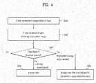
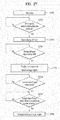
- FIG. 4 is a flowchart showing an operation of a mobile terminal 100 according to one embodiment of the present invention.
- the controller 180 may create a plurality of representative images related to the video (S401).
- the controller 180 may set at least one of the video's plurality of frames as a representative image or create a representative image based on audio content contained in the video.
- the representative image may comprise multiple sub-representative images arranged within the larger representative image so that each sub-representative image may be easily recognized.
- the controller 180 may set as a representative image: one or multiple frames corresponding to a specific playing time of the video, a frame contained in a highlight period of the video, a frame corresponding to an appearance time of a specific character in the video, a frame corresponding to the generation of a specific sound in the video, or an image created by displaying text converted from audio during a specific period of the video.
- a representative image one or multiple frames corresponding to a specific playing time of the video, a frame contained in a highlight period of the video, a frame corresponding to an appearance time of a specific character in the video, a frame corresponding to the generation of a specific sound in the video, or an image created by displaying text converted from audio during a specific period of the video.
- the mobile terminal 100 may divide a video into a plurality of periods and extract a representative image from each divided period to create a plurality of representative images.
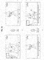
- FIG. 5 is a diagram showing an example in which the whole period of video is divided into a plurality of periods and a representative image is extracted from each divided period.
- the controller 180 extracts four representative images and that a progress bar 500 shown in FIGs. 5(a) and 5(b) corresponds to the whole period of video.
- the controller 180 may divide the whole period of the video into four periods 510, 520, 530, and 540 as shown in FIG. 5(a) . Subsequently, the controller 180 may decide frames 512, 522, 532, and 542 to be representative images of the respective divided periods 510, 520, 530, and 540, as shown in FIG. 5(b).
- FIG. 5(b) illustrates that frames 512, 522, 532, and 542 corresponding to a mid-way point within the respective divided periods 510, 520, 530, and 540.
- the controller 180 may decide frames corresponding to other playing times (e.g. start time or end time of the respective periods) other than the mid-way point in the illustrated example as representative images.
- frames corresponding to different playing times of the respective divided periods may be decided as representative images.
- the controller 180 may select a frame corresponding to N/4 playing time (or (N-1)/4 playing time, or any other determination based on N), where N represents the ordinal number of the period, as a representative image for each of the four periods 510, 520, 530, and 540 shown in FIG. 5(a) .
- N represents the ordinal number of the period
- a frame corresponding to 1/4 playing time (or start time) of the first period 510 may be decided as a representative image
- a frame corresponding to 2/4 playing time (or 1/4 playing time) of the second period 520 may be decided as a representative image.
- FIG. 5(b) illustrates that one representative image is extracted for each of the divided periods. Of course, however, two or more representative images may be extracted for each of the divided periods.
- a video such as a movie
- the video may also contain a trailing conclusion portion to display information such as movie staff and other contributors. Since it is difficult for a user to recognize the content of the movie by viewing a frame of these leading or trailing portions, the controller 180 may extract a representative image from the video after excluding a leading period and a trailing period. To this end, the controller 180 may extract a representative image from the remaining period after excluding a specific predetermined leading period of the video and a specific predetermined trailing period of the video. The details thereof will be described with reference to FIG. 6 .
- FIG. 6 is a diagram showing an example in which the remaining period of video excluding a specific period is divided into a plurality of periods and a representative image is extracted from each divided period.
- the controller 1880 may divide the remaining period of the video, after excluding a specific predetermined leading period (a) (of FIG. 6(a) ) and a specific predetermined trailing period (b) of the video, into four periods 610, 620, 630, and 640. Subsequently, the controller 180 may set at least one frame per divided period, 612, 622, 632, and 642 extracted from the respective divided periods 610, 620, 630, and 640, as representative images as shown in FIG. 6(b) .
- the mobile terminal 100 may set a highlight period in video and extract a representative image from the set highlight period.
- the controller 180 may set at least one representative image selected from the most dynamic period in the video, a period containing the loudest sound in the video, and the brightest period in the video as a highlight period.
- Speed of a subject recorded in the video may be considered to find the most dynamic period in the video.
- the controller 180 may set the highlight period of the video as a period in which the subject moves the fastest.
- Intensity of a sound recorded in the video may be considered to find a period containing the loudest sound in the video.
- the controller 180 may set a period containing the highest intensity of a sound recorded in the video as a highlight period. For example, in a case in which the video is related to a baby, a period of the video in which the baby makes the loudest voice (e.g. a period of the video in which the baby cries) may be set as a highlight period.
- Brightness of each frame of the video may be considered to find the brightest period in the video.
- the controller 180 may set a period of the video having the highest brightness as a highlight period. For example, in a case in which the video is related to fireworks, a period of the video in which the fireworks are lit as be set as a highlight period.
- the controller 180 may extract a representative image from the set highlight period.
- the controller 180 may extract one representative image or a plurality of representative images from the highlight period.
- a plurality of highlight periods may be set in the video to extract a plurality of representative images.
- FIG. 7 is a diagram showing an example in which a highlight period is set in video and a representative image is extracted from the set highlight period.
- the controller 180 may set at least one highlight period considering movement speed of a subject recorded in the video, intensity of a sound recorded in the video, and brightness of the video ( FIG. 7(a) illustrates an example in which four highlight periods 710, 720, 730, and 740 are set).
- the controller 180 may extract representative images 712, 722, 732, and 744 from the set highlight periods 710, 720, 730, and 740. Specifically, the controller 180 may decide frames 712, 722, 732, and 742 corresponding to specific playing time of the respective highlight periods 710, 720, 730, and 740 as representative images.
- FIG. 7(b) illustrates that frames 712, 722, 732, and 744 corresponding to a mid-point of the respective highlight periods 710, 720, 730, and 740 are decided as representative images.
- frames corresponding to playing time e.g. start time or end time of the respective highlight periods
- other than the mid-point in the illustrated example may be decided as representative images.
- frames corresponding to different playing time of the respective highlight periods may be decided as representative images.
- the controller 180 may control a frame corresponding to N/4 playing time (or (N-1)/4 playing time) of an N-th highlight period to be decided as a representative image for each of the four highlight periods 710, 720, 730, and 740 shown in FIG. 7(a) .
- a frame corresponding to 1/4 playing time (or start time) of the first highlight period 710 may be decided as a representative image and a frame corresponding to 2/4 playing time (or 1/4 playing time) of the second highlight period 720 may be decided as a representative image.
- the mobile terminal 100 may create a representative image for each character that appears in a video.
- An example in which a representative image per character is created will be described in detail with reference to FIG. 8 .
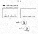
- FIG. 8 is a diagram showing an example in which a representative image per character is created.
- the controller 180 may set any one of frames containing a specific character as a representative image of the character. For example, in a case in which there exists a total of two periods 810 and 820 containing character A as in an example shown in FIG. 8(a) , the controller 180 may extract at least one frame 812 from the two periods 810 and 820 to create a representative image of character A. In the same manner, the controller 180 may extract at least one frame 814 from periods 830 and 840 containing character B to create a representative image of character B.
- the controller 180 may extract a frame best expressing the specific character.
- the frame best expressing the specific character may be a frame in which the specific character has the largest role, is displayed the largest, or is distinctly or most prominently displayed based on brightness, sharpness, or other appearance characteristics.
- the controller 180 may first create a representative image of a character having high relative importance in consideration of at least one selected from appearance frequency and appearance time per character. For example, in a case in which the number of representative images to be created is two and the number of characters in video is four, the controller 180 may create representative images of two characters having high relative importance considering the relative importance of the characters.
- the mobile terminal 100 may create a representative image of a video based on previous events related to the mobile terminal.
- the controller 180 may select representative images of a video based on the appearance of a person or party who is a participant or subject of a previous event related to the mobile terminal.
- the number of representative images and the order in which they are selected from the video displaying each person or party may be based on the number of related events involving the person or party and the order in which the events took place.
- an event related to the mobile terminal may include a telephone communication, the transmission or reception of a message (a text message or an instant message), a conversation using a social network service (SNS), or an event scheduled on a calendar, appointment log, or to-do list.
- the person or party involved with an event may include telephone communication participant, a counterpart person or party for the transmission or reception of a message, a counterpart person or party for a conversation using an SNS, or a person who holds a scheduled appointment, or an invitee or inviter of a scheduled event.
- FIG. 9 is a diagram showing an example in which a representative image of another person or party is selected from a video.
- the event is telephone communication and that representative images are created in the order in which the latest events have been generated at the mobile terminal.
- FIG. 9(a) is a diagram showing the communication details of the mobile terminal 100
- FIG. 9(b) is a diagram showing an example in which a representative image is created based on the communication details of the mobile terminal 100.
- the controller 180 may extract a predetermined number of frames containing the other party involved in the telephone communication from the video in the order in which the latest event has been generated based on the communication details of the mobile terminal 100. In a case in which there is no frame containing the other party involved in the most recent telephone communication at the mobile terminal, the controller 180 may extract a frame containing the other party involved in the telephone communication which took place second-most recently, and so on.
- a frame 912 containing Jane and a frame 922 containing Tom are decided as representative images in order of the user's latest communication.
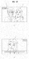
- the mobile terminal 100 may convert voice audio in a specific period of the video into text (speech to text (STT)) and create a representative image based on the text. The details thereof will be described with reference to FIG. 10 .
- FIG. 10 is a diagram showing an example in which a representative image is created based on text corresponding to voice audio played in a specific period of a video.
- the controller 180 may convert voice audio in a specific period 1010 into text (STT) and create a representative image based on the converted text as in an example shown in FIG. 10(a) or 10(b) .
- the controller 180 may create a representative image 1012 in which the converted text is displayed on a monochromatic background as in an example shown in FIG. 10(a) or a representative image 1014 in which the converted text is displayed on a frame corresponding to specific point within a period 1010 from which the voice audio has been extracted as a background, as shown in FIG. 10(b) .
- the controller 180 may randomly decide a period of the video from which the voice audio clip is to be extracted or may use a predetermined number of periods selected from the video in which the loudest voice audio clips are reproduced.
- the mobile terminal 100 may extract a plurality of representative images from a video based on a photograph related to the video.
- the photograph related to the video may be manually selected by a user or it may be automatically selected according to a predetermined criterion.
- the controller 180 may automatically select a photograph related to the video based on at least a time the photograph was taken, a location where the photograph was taken, or a person or character appearing in the photograph.
- the controller 180 may select a photograph taken before or after the video recording date (or a photograph taken at the same date as the video), a photograph taken at the same location as the video, or a photograph containing the same person or character as in the video.
- the controller may select as a related photograph a photograph which appears adjacent to video when a multimedia file list is displayed.
- the controller 180 may extract a plurality of representative images from the video based on information of the photograph related to the video. For example, the controller 180 may extract a period analogous to the photograph, such as a period containing the same character as in the photograph, a period containing the same object as in the photograph, or a period containing the same background as in the photograph, and extract at least one frame from the extracted period as a representative image.
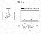
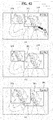
- FIGs. 11A and 11B are diagrams showing an example in which a representative image is extracted from a video based on a related photograph.
- FIGs. 11A(a) and 11B(a) are diagrams showing photographs related to the video and
- FIGs. 11A(b) and 11B(b) are diagrams showing representative images extracted from the video.
- the controller 180 may extract from the video a period containing the same character as in the photograph.
- the controller 180 may create at least one representative image 1112 and 1114 from the extracted period as in an example shown in FIG. 11A(b) .
- the controller 180 may extract at least one selected from a period in which the characters have been simultaneously recorded and a period in which the characters have been individually recorded from the video. Specifically, in a case in which a plurality of characters in the photograph is referred to as a first character and a second character in an example shown in FIG. 11B(a) , the controller 180 may control a period containing both the first character and the second character, a period containing the first character, and a period containing the second character to be selected and at least one representative image 1122 and 1124 to be created from each period as shown in FIG. 11B(b) . Then, the controller 180 may create a representative image from the period containing both the first character and the second character.
- a plurality of photographs may be decided as photographs related to the video.
- the controller 180 may extract a period related to each photograph from the video and create at least one representative image from each extracted period.
- a photograph related to the video may be at least one selected from among a photograph taken before or after a video recording (or a photograph taken at the same date as in the video), a photograph taken at the same place as the video, or a photograph containing the same character as in the video.
- a photograph related to the video may be a photograph located adjacent to video when a multimedia file list is displayed.
- FIG. 12 is a diagram illustrating an example in which a photograph located adjacent to video when a multimedia file list is displayed is selected as a photograph related to the video.
- the controller may select as a related photograph a photograph 1204 located next (or previous) to video 1202 when a multimedia file list is displayed.
- photograph '20120102.jpg' 1204 located next to the video 1202 may be decided as a photograph related to the video.
- a plurality of photographs located next (or previous) to the video may be set as photographs related to the video or all photographs displayed on the same screen as the video may be set as photographs related to the video.
- both photograph '20120102.jpg' 1204 and photograph '20120103.jpg' 1206 displayed on the same screen as the video 1202 may be set as photographs related to the video.
- the mobile terminal 100 may extract a plurality of representative images from a video based on a keyword.
- the controller 180 may extract a period containing a character indicated by the input keyword, a period containing an object indicated by the input keyword, or a period containing voice audio matched with the input keyword and extract at least one frame from the extracted period as a representative image.
- FIG. 13 is a diagram showing an example in which a representative image is extracted based on a keyword.
- FIG. 13(a) is a diagram illustrating a keyword input by a user and
- FIG. 13(a) is a diagram showing an example in which a representative image is extracted from a period of the video related to the input keyword.
- the controller 180 may extract a period of the video containing the character indicated by the input keyword and at least one representative image 1312 and 1314 to be created from the extracted period as in the example shown in FIG. 13(b) .
- a representative image may be created based on the text converted from the voice audio in the extracted period (STT) as previously described in connection with Case 5.
- the controller 180 may extract a representative image using a keyword previously input by the user as a web search. Alternatively, the controller 180 may create a representative image based on a keyword input in a search window while a multimedia file list is displayed as in the example shown in FIG. 13(a) .
- the mobile terminal 100 may create a plurality of representative images using the above-described representative image creating methods together. For example, some of the representative images may be created using one of the methods according to Case 1 to Case 7 and the other representative images may be created using another of the methods according to Case 1 to Case 7.
- the controller 180 may create one representative image according to a conventional method (i.e. extract one corresponding to random or predetermined time of all the frames of the video) and the other representative images may be created using at least one of the other methods according to Case 1 to Case 7.
- the controller 180 may randomly decide a thumbnail creating criterion whenever it is required to create a thumbnail. For example, the controller 180 may create a representative image using one of the methods according to Case 1 to Case 7 when it is required to create a first thumbnail and create a representative image using another of the methods according to Case 1 to Case 7 when it is required to create the next thumbnail. It may be required to create a new thumbnail when a multimedia file list is to be displayed, when a new file is added to the multimedia file list, and when a sorting criterion of the multimedia file list is changed.
- the controller 180 may randomly decide frame extraction times when it is necessary to create a thumbnail. For example, in a case in which a representative image is to be created using the method according to Case 1, the controller 180 may decide a frame corresponding to a mid-point of each period as a representative image for a first thumbnail, and decide a frame corresponding to a 3/4 point of each period when it is required to create the next thumbnail.
- the controller 180 may create a thumbnail containing the representative images (S402). Specifically, the controller 180 may create a thumbnail containing the representative images by arranging the representative images in a predetermined order. A thumbnail containing a plurality of representative images will be described in detail with reference to FIG. 14 .
- FIG. 14 is a diagram illustrating a thumbnail containing a plurality of representative images.
- the controller 180 may set a plurality of representative images 1412, 1414, 1416, and 1418 such that the representative images 1412, 1414, 1416, and 1418 have the same size, and may arrange the representative images 1412, 1414, 1416, and 1418 in a tile pattern to create a thumbnail as in an example shown in FIG.
- the controller 180 may arrange a plurality of representative images 1432, 1434, 1436, and 1438 as if the representative images 1432, 1434, 1436, and 1438 are thrown on the floor or table to create a thumbnail as in an example shown in FIG. 14(c) .
- the controller 180 may control any one of a plurality of representative images 1442, 1444, 1446, and 1448 to be set as a background image 1448 and the other representative images 1442, 1444, and 1446 to be displayed on the background image 1448 in an overlay fashion as in an example shown in FIG. 14(d) .
- the representative images 1442, 1444, and 1446 displayed on the background image 1448 in the overlay fashion may be set to be semitransparent.
- the controller 180 may decide an arrangement sequence of representative images based on a time order of the representative images or a degree of importance of the representative images.
- the controller 180 may use a degree of importance of the characters appearing in the representative images to determine an arrangement sequence. Specifically, the controller 180 may determine that a representative image of a character having higher relative importance in appearance has a higher degree of importance.
- the relative importance in appearance of the characters may be decided based on appearance frequency or appearance time per character.
- the controller 180 may determine a degree of importance of the representative images based on an order in which the events occurred and the number of times each event occurred. Specifically, the controller 180 may determine that a representative image of the other person or party related to the most recent event or the other person or party having of the highest frequency of involvement in previous events has a higher degree of importance.
- the controller 180 may decide a degree of importance of the representative images based on dynamic movement of the displayed subjects or characters, loudness or volume of the corresponding audio, or the brightness of each highlight period.
- the controller 180 may control information related to the representative images contained in the thumbnail and displayed on the respective representative images.
- information related to a representative image may include information regarding the playing time corresponding to the representative image or information regarding a character related to the representative image.
- the controller 180 may control information regarding the playing time corresponding to each representative image to be displayed as in the example shown in FIG. 14(a) or may control information regarding a character related to each representative image to be displayed (in FIG. 14(b) , the name of the character is displayed) as in the example shown in FIG. 14(b) .
- FIG. 14 illustrates that a thumbnail is created based on four representative images, the thumbnail may be created based on a less number or a more number of representative images.
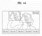
- the controller 180 may assign a portion of the thumbnail as a video playing region and the other portion of the thumbnail as a representative image region.
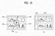
- FIG. 15 is a diagram illustrating a video playing region and a representative image region of a thumbnail.
- the controller 180 may assign a portion of the thumbnail as a video play command region 1510 and the other portion of the thumbnail as a representative image region 1520.
- FIG. 15(a) illustrates that the video playing region 1510 is set to be located at the middle of the thumbnail and
- FIG. 15(b) illustrates that the video play command region 1510 is set to be located at one end of the thumbnail.
- the controller 180 may control information (e.g. a triangular playing indicator or text to indicate a play command region) to visually distinguish the video play command region 1510 to be displayed.
- information e.g. a triangular playing indicator or text to indicate a play command region
- the controller 180 may play the video (S404). Specifically, when the video play command region is touched or receives an input, the controller 180 may play the video from the beginning or start to play the video from a point where the previous playing of the video was stopped.
- the controller 180 may start to play the video from time indicated by the representative image selected by the touch or play the video only during the period represented by the representative image selected by the touch (S405).
- FIG. 16 is a diagram illustrating operation of the mobile terminal 100 when the video play command region is touched.
- the controller 180 may play the video.
- the controller 180 may play the video from the beginning as in the example shown in FIG. 16(b) or start to play the video from a point where the previous playing of the video was stopped (not depicted).
- the controller 180 may control each representative image constituting the thumbnail of the video and the position of each representative image to be displayed on a progress bar indicating a playing time of the video as in the example shown in FIG. 16(b) .
- the controller 180 may control the current playing time to be changed to playing time corresponding to the selected representative image.
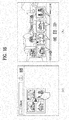
- FIGs. 17 , 18 , 19A , and 19B are diagrams illustrating operation of a mobile terminal 100 when a representative image region is touched.
- representative images contained in a thumbnail will be referred to as first to fourth representative images I to IV in a clockwise direction.
- the controller 180 may control the video to be played from a point corresponding to the representative image selected by the touch. For example, when the first representative image I is touched as in an example shown in FIG. 17(a) , the controller 180 may control the video to be played from the playing time (00:02:00 in FIGs. 17(a) and 17(b) ) corresponding to the first representative image I as in an example shown in FIG. 17(b) .
- the controller 180 may control the video to be played from the playing time (00:02:00 in FIGs. 17(a) and 17(b) ) corresponding to the first representative image I as in an example shown in FIG. 17(b) .
- each representative image constituting the thumbnail of the video and the position of each representative image may be displayed on the progress bar indicating playing time of the video as in the example shown in FIG. 16(b) .
- the controller 180 may control the video to be played only during the period represented by the representative image selected by the touch.
- the controller 180 may control the video to be played only during the period represented by the first representative image I.
- a period represented by a representative image may be any one period when the whole video is divided into a plurality of periods (see Case 1), a highlight period (see Case 2), a period containing a specific character (see Case 3, Case 4, Case 6, and Case 7), or a period containing voice audio corresponding to specific text or keyword (see Case 5 and Case 7).
- the controller 180 may control the video to be played only during the plurality of periods indicated.
- the controller 180 may play the video only during the plurality of periods as in the example shown in FIG. 19(b) . Consequently, it is possible for a user to easily and conveniently view only the periods in which the specific character appears from the entire video.
- the controller 180 may play the video during periods in which the specific character appears prominently or in which particular focus is placed on the specific character. This may mean that the video is enlarged or zoomed-in based on where the specific character appears in the frame during the portion of the video. For example, when the first representative image I representing the specific character is touched as shown in FIG. 19B(a) , the controller 180 may control the video to be enlarged during playback to focus in on the specific character as shown in FIG. 19B(b) .
- the controller 180 may display a zoom indicator while playing the enlarged video indicating the position and size of the displayed region with respect to the entire frame of the video such that a user can estimate the position and size of the enlarged region.
- the controller 180 may playback only the audio corresponding to the period of the video represented by the representative image without outputting the video portion of the video. It is possible to minimize power consumption of the mobile terminal 100 by playing back only the audio portion of the video to be output without outputting the video portion of the video.
- the controller 180 may decide whether only the audio portion of the video is to be output based on the state of the mobile terminal 100. For example, in a case in which the mobile terminal 100 is in a power saving mode or the remaining power capacity of the mobile terminal 100 is at a predetermined level or less, the controller 180 may playback only the audio portion of the video without outputting the video portion in order to minimize power consumption of the mobile terminal 100.
- the controller 180 may initiate a communication operation with that person or party when the representative image is touched or selected.
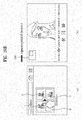
- An example of such an embodiment will be described in detail with reference to FIG. 20 .
- FIG. 20 is a diagram showing an example in which a screen to communicate with another person or party corresponding to a representative image selected by a touch is displayed.
- representative images contained in a thumbnail will be referred to as first to fourth representative images I to IV in a clockwise direction.
- the controller 180 may control a screen to be displayed to communicate with the person or party corresponding to the representative image selected by the touch.
- the controller 180 may control a popup window 2010 to be displayed listing communication options to communicate with the person or party corresponding to the first representative image I as shown in FIG. 20(b) .
- communication options to communicate with a specific person or party may include a text message, telephone communication, an SNS, or messaging.
- the controller 180 may control a corresponding application to be executed. For example, when a Messaging option is selected in FIG. 20(b) , the controller 180 may control a text message application to be displayed. At this time, the controller 180 may further control the corresponding application such that the person or party corresponding to the first representative image I is automatically designated or populated as a recipient of the selected communication application.
- the controller 180 may control information regarding the person or party corresponding to the representative image to be searched for on the web. Specifically, the controller 180 may search for the person or party via a portal search site using information related to the person or party, such as name or image.
- the mobile terminal 100 may distinguish between a first type touch input and a second type touch input to the representative image region.
- the playing of the video may be started from a time indicated by the representative image or the video may be played only during the period represented by the representative image selected by the touch as illustrated in FIGs. 16 to 19 .
- a screen to communicate with the person or party corresponding to the selected representative image may be displayed as in the example shown in FIG. 20 .
- the first type touch input and the second type touch input may be any selected from among a simple touch (a touch to the representative image region being released within a predetermined time), a long touch (a touch to the representative image region being maintained for a predetermined time), or a plurality of tapping inputs (the representative image region being touched a plurality of times within a time period).
- the embodiment of FIG. 4 illustrates that the controller 180 creates a plurality of representative images from a video to create a thumbnail of the video.
- the control 180 may combine a representative image created from a video and a representative image of a photograph related to the video to create a thumbnail of the video.
- the controller 180 may select a photograph related to the video based on a capture time, a capture location, or a person or character appearing in the photograph. For example, the controller 180 may select a photograph taken before or after the video recording (or a photograph taken on the same date as the video), a photograph taken at the same location as the video, or a photograph containing the same person or character as the video.
- a representative image of a photograph related to the video may mean a thumbnail of the photograph.
- FIG. 21 is a diagram showing an example in which a representative image of video and a representative image of a photograph related to the video are combined to create a thumbnail of the video.
- the controller 180 may combine representative images 2110 and 2120 extracted from video and photographs 2130 and 2140 related to the video to create a thumbnail of the video as in an example shown in FIGs. 21(a) and 21(b) .
- the controller 180 may control an indicator 2150 to be displayed indicating whether a representative image was extracted from the video or is a photograph related to the video as shown in FIG. 21(b) (FIG. 21(b) illustrates that indicators 2150 are displayed on only the representative images of the photographs related to the video).
- the controller 180 may control the photograph to be displayed.
- the controller 180 may display a thumbnail of a folder containing multimedia files, such as videos and photographs.
- the controller 180 may combine at least some of the multimedia files belonging to the folder to create a thumbnail of the folder.
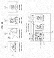
- FIG. 22 is a diagram illustrating an example in which a thumbnail of a folder is created.
- FIG. 22(a) is a view showing thumbnails 2210, 2220, and 2230 of multimedia files contained in a folder and
- FIG. 22(b) is a view showing a thumbnail of the folder.
- FIG. 22(a) illustrates that a thumbnail of video contains four representative images 2212, 2214, 2216, and 2218.
- the controller 180 may combine the thumbnails 2212, 2214, 2220, and 2230 of the multimedia files contained in the folder to create a thumbnail of the folder.
- the thumbnail 2210 of the video contains a plurality of representative images 2212, 2214, 2216, and 2218 as in an example shown in FIG. 22(a)
- the thumbnail of the folder does not necessarily need to contain all the representative images contained in the video as in an example shown in FIG. 22(b) but it is sufficient for the thumbnail of the folder to contain at least one of the representative images contained in the thumbnail of the video.
- the controller 180 may sort the multimedia files based on date, file size, file name, or location of capture to determine an arrangement sequence of the thumbnails of the multimedia files.
- the controller 180 may restrict the number of images to be contained in the thumbnail of the folder to a predetermined number.
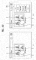
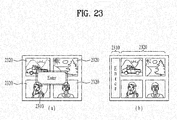
- FIG. 23 is a diagram illustrating an entry region and a link region of a thumbnail.
- the controller 180 may set a portion of the thumbnail of the folder as an entry region 2310 and the other portion of the thumbnail of the folder as a link region 2320.
- FIG. 23(a) illustrates that the entry region 2310 is set to be located at the middle of the thumbnail
- FIG. 23(b) illustrates that the entry region 2310 is set to be located at one end of the thumbnail.
- the controller 180 may control information to visually distinguish the entry region to be displayed.
- the controller 180 may control a multimedia file list contained in the folder to be displayed.
- the controller 180 may control a multimedia file corresponding to a position selected by the touch to be directly output without displaying the multimedia file list.
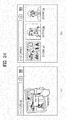
- FIGs. 24 and 25 are diagrams illustrating operation when an entry region of a folder thumbnail is touched and when a link region of a folder thumbnail is touched.
- the controller 180 may control a multimedia file list contained in the folder to be displayed as in an example shown in FIG. 24(b) .
- the controller 180 may control a multimedia file 2510 designated by touch input to be directly output as in an example shown in FIG. 25(b) .
- the controller 180 may control a thumbnail containing a plurality of images (e.g. a thumbnail of video or a thumbnail of a folder) to be enlarged.
- a thumbnail containing a plurality of images
- the thumbnail is enlarged, it is possible for the user to view a plurality of images contained in the thumbnail in more detail and to improve user convenience in manipulating the thumbnail (e.g. to increase a touch region according to the increase in area of the playing region and the representative image region).
- FIG. 26 is a diagram showing an example in which a thumbnail containing a plurality of images is enlargedly displayed.
- the controller 180 may control an enlarged thumbnail to be displayed in a popup window as in an example shown in FIG. 26 .
- FIG. 26 illustrates long touch of the playing region (or the entry region) as user input to enlarge the thumbnail
- touch input other than what is shown may be assigned to enlarge the thumbnail.
- a pinch out gesture input to increase the distance between two pointers while touching the display 151 may be assigned as user input to enlarge the thumbnail.
- the controller 180 may control the thumbnail to be reduced again.
- FIGs. 42A and 42B illustrate that when a specific representative image representing a specific character is touched, the video is played in an enlarged size based on the character corresponding to the touched specific representative image.
- the mobile terminal may set an object to be tracked during playing of video and enlarge the video being played based on the set object.
- the terms "whole region” and “focus region” are inserted when referring respectively to the entire region of the video or a zoomed in portion of the video being displayed in an enlarged size.
- FIG. 27 is a flowchart showing operation of a mobile terminal according to one embodiment of the present invention.
- the controller 180 may control video to be played and the played video to be output through a touchscreen (S2701).
- the video described in the present invention may mean video stored in the memory 160, video received from a remote terminal (or server) and played in a streaming mode, video received in real time from a terminal of another person or party for communication during video communication, and video recorded in real time through the camera 121.
- the controller 180 may pause playing of the video until a target object, among objects displayed in the video, is set (S2703).
- the tracking function may mean a series of functions to track and display motion of any one of the objects displayed on the video and the objects may mean people, animals, and things.
- FIG. 28 is a diagram illustrating an example in which playing of video is paused in response to user input to enable a tracking function.
- the controller 180 may control playing of the video to be paused and a video frame to be output as in an example shown in FIG. 28(b) .
- a message may be displayed showing an example of a user input to enable a tracking function, as well as a tracking icon 520 which can be used to set the target object to be displayed as in an example shown in FIG. 28(b) .
- FIG. 28(a) illustrates touching the predetermined button ('smart tracking' button) 2810 as user input to enable a tracking function.
- the predetermined button 'smart tracking' button
- tapping the touchscreen a predetermined number of times during the playing of the video, flicking a pointer in a predetermined direction, simultaneously touching N number of pointers to the touchscreen, or flicking N number of pointers in a predetermined direction may be set as user input to enable the tracking function, as well as any other gestures or touch combinations without limitation.
- the controller 180 may control the playing of the video to be paused. In a case in which the resolution of the video during playback is greater than the predetermined resolution, on the other hand, the controller 180 may output a message to inform that the tracking function cannot be enabled in the video and the playback continued without application of the following process.
- the resolution of the video is too high, the computation amount required by the controller 180 is increased, with the result that power consumption may be increased and performance may be deteriorated due to heat generated therefrom. For this reason, the tracking function may be enabled only in a case in which the resolution of the video is equal to or less than the predetermined resolution, however, these considerations shall not be construed as limiting the present disclosure.
- the controller 180 may pause playing of the video until a target object, among objects displayed in the video, is set (S2703).
- the user may select or unselect at least one of objects displayed in a still image to decide an object to be set as a target object.
- various input examples may be applied as user input to select or unselect at least one of the objects displayed in the still image.
- an object to be set as a target object may be selected or unselected by simply touching one object displayed in the still image, dragging a tracking icon (e.g. the tracking icon 2820 of FIG. 28(b) ) displayed in the still image onto an object to be set as a target object, and touching at least one of icons representing candidate objects (see FIG. 29(b) , which will hereinafter be described).
- object selecting or unselecting methods that can be obviously invented by those of ordinary skill in the art to which the present invention pertains falls within the protection scope of the current disclosure.
- the controller 180 may control candidate objects that can be set as a target object to be visually distinguished.
- FIG. 29 is a diagram illustrating an example in which candidate objects that can be set as a target object are visually distinguished.
- the controller 180 may control image objects 612 and 614 (illustrated as a square frame in FIG. 29(a) ) indicating candidate objects which can be set as a target object to be displayed in the vicinity of the candidate objects as in an example shown in FIG. 29(a) .
- controller 180 may control icons 622 and 624 representing candidate objects which can be set as a target object to be displayed at one side of the touchscreen as in an example shown in FIG. 29(b) .
- touch input for at least one of the icons 622 and 624 representing the candidate objects may be set as user input to set the candidate objects as the target object.
- the controller 180 may enlarge or reduce the display size of the candidate objects which can be set as the target object or change a color of the candidate objects to inform the user of the candidate objects which can be set as the target object.
- candidate object distinguishing methods that can be obviously invented by those of ordinary skill in the art to which the present invention pertains fall within the protection scope of the current disclosure.
- the playing of the video does not necessarily need to be paused in response to the user input to enable the tracking function.
- the controller 180 may set a target object while continuing to play the video.
- the controller 180 may control the candidate objects that can be set as the target object to be visually distinguished while playing the video.
- the candidate objects that can be set as the target object and the position of the candidate objects may be changed over time.
- the controller 180 may control at least a portion of the video to be set as a focus region which is changed according to the motion of the target object during the video and then set focus region to be displayed through the touchscreen (S2705). That is, the controller 180 may control the video to be played based on the set target object.
- FIG. 30 is a diagram illustrating an example in which at least a portion of video is set as a focus region. For the convenience of description, it is assumed that two characters are displayed in the video and the two characters will be referred to as a first character I and a second character II.
- the controller 180 may set at least a portion of the video as a focus region based on the target object. That is, the controller 180 may control a focus region 3010, of the whole region of the video, to be set based on the target object (i.e. the second character II) as in an example shown in FIG. 30(a) .
- the controller 180 may control the position of a focus region 3020 to be changed according to the second character II as in an example shown in FIG. 30(b) .
- a tracking algorithm such as a face recognition algorithm, a shape recognition algorithm, or a color recognition algorithm, may be used as an algorithm to track motion of the target object.
- the tracking algorithm is well-known technology and, therefore, a detailed description thereof will be omitted.
- the size of the focus region may have a fixed value irrespective of the size of the target object.
- the controller 180 may control the size of the focus region to be changed according to the size of the target object. An example in which the size of the focus region is changed according to the size of the target object will be described in detail with reference to FIG. 31 .
- FIG. 31 is a diagram illustrating an example in which the size of a focus region is changed. For the convenience of description, it is assumed that one of first and second characters I and II, e.g. the second character II, is set as a target object.
- the controller 180 may control a focus region 810 to be set based on the second character II set as the target object. At this time, a ratio of the focus region 810 to the whole region of the video may be decided according to the size of the second character II in the video. In a case in which the size of the second character II is decreased as the video is played, the controller 180 may control a ratio of a focus region 820 to the whole region of the video to be decreased as in an example shown in FIG. 31(b) . Although not shown, when the size of the second character II is increased, on the other hand, the controller 180 may control a ratio of the focus region to the whole region of the video to be increased.
- the controller 180 may emphasize and output a voice of the target object while outputting the focus region.
- the controller 180 may control the output level (or volume) of a voice signal determined as the voice of the second character II to be raised higher than other sounds, such that the voice of the character set as the target object is emphasized and output.
- the controller 180 may extract a voice signal of the target object based on a detected motion of the mouth or lips of the target object. Alternatively, the controller 180 may extract a voice signal of the target object based on the position of the target object in a stereo environment.
- the controller 180 may control a zoom indicator indicating the position and size of the focus region, of the whole region of the video, to be displayed such that a user can estimate the position and size of the focus region.
- FIG. 32 is a diagram illustrating an example in which a zoom indicator is output.
- the controller 180 may control the set focus region 910 to be displayed as in an example shown in FIG. 32(b) while playing the video.
- the controller 180 may control a mini map 920 indicating the position and size of the focus region 910, of the whole region of the video, to be displayed as in the example shown in FIG. 32(b) .
- an outer rectangle 922 may correspond to the whole region of the video and an inner rectangle 924 may correspond to the focus region 910.
- the controller according to the present invention may set at least one object as a target object based on user input. That is, the target object does not necessarily mean a single object.
- the controller 180 may control a plurality of playing windows to be output and focus regions of the target objects to be output through the respective playing windows. Operation of the mobile terminal 100 when a plurality of target objects is set as target objects will be described with reference to FIG. 33 .
- FIG. 33 is a diagram illustrating the output of a touchscreen when a plurality of target objects is set. For the convenience of description, it is assumed that two characters displayed in video are set as target objects.
- the controller 180 may set a focus region for each target object as in an example shown in FIG. 33(a) . Specifically, the controller 180 may set a first focus region 1010 based on a first character I and a second focus region 1020 based on a second character II as in an example shown in FIG. 33(a) .
- the controller 180 may control a plurality of playing windows 1030 and 1040 corresponding to the target objects to be output and each focus region to be displayed through a corresponding one of the playing windows as in an example shown in FIG. 33(b) .
- the controller 180 may control the first focus region 1010 for the first character I to be output through the first playing window 1030 and the second focus region 1020 for the second character II to be output through the second playing window 1040 as in an example shown in FIG. 33(b) .
- the position and size of the first playing window 1030 and the second playing window 1040 shown in FIG. 33(b) are merely illustrative and, therefore, the present invention is not limited thereto.
- the first playing window 1030 and the second playing window 1040 may have different sizes.
- the first playing window 1030 and the second playing window 1040 may be displayed in an overlapping fashion.
- the second playing window 1040 may be displayed in the first playing window 1030 as picture in picture (PIP).
- a target object may not appear in the video at all times or such a target object may not be able to be tracked due to technical limitations of a tracking algorithm. In a case in which the target object cannot be tracked as the video is played
- the controller 180 may retry recognition of the target object after a predetermined time.
- the controller 180 may control tracking of the target object to be interrupted or playing time of the video to be changed to a point in the video when the target object reappears (S2708).
- N is a natural number including 1 and may be a value that can be adjusted by the user.
- N is set to 1
- tracking of the target object may be interrupted or playing time of the video may be changed immediately when the recognition of the target object fails.
- FIG. 34 is a diagram illustrating the change in output of a touchscreen when tracking of a target object is interrupted.
- the controller 180 may control a popup window 1110 indicating that the target object cannot be recognized from the video to be displayed.
- the controller 180 may interrupt tracking of the target object and may control the whole region of the video to be output (if the focus region was being displayed in an enlarged size) while playing the video as in an example shown in FIG. 34(b) .
- the controller 180 may interrupt tracking of the target object and may control the playing of the video to be paused such that the user can reset the target object as in an example shown in FIG. 34(c) .
- an information message and a tracking icon may be displayed as previously described with reference to FIG. 28 .
- the controller 180 may control the video to be automatically played at a point in which the target object reappears in the video.
- FIG. 35 is a diagram illustrating an example in which playing time of video is changed to a reappearance point of a target object.
- the controller 180 may cause the video to be automatically played at a point in which the target object reappears in the video (e.g.
- the controller 180 may control the playing time of video to be changed to time when the target object reappears at the next point in time of the remaining playing period of the video.
- the controller 180 may terminate tracking and control tracking of the target object to be finished at time when the recognition of the target object fails as in the example shown in FIG. 34 .
- the controller 180 may display a period during which the target object appears to be displayed in a visually distinguished state while outputting a playing status display bar indicating the playing time of the video.
- FIG. 36 is a diagram illustrating an example in which a period during which the target object appears is distinctly displayed or indicated on a playing status display bar.
- the controller 180 may control the periods d1 to d3 in which the target object appears to be visually distinguished (e.g. the periods d1 to d3 may be expressed using predetermined colors) on the playing status display bar as in an example shown in FIG. 36(a) .
- the controller 180 may control only the start points of the three periods in which the target object appears to be visually distinguished as in an example shown in FIG. 36(b).
- FIG. 36(b) illustrates an example in which indication windows 1312, 1314, and 1316 indicating the respective start points of the three periods d1 to d3 are displayed while images corresponding to the start points indicated by the indication windows 1312, 1314, and 1316 are displayed.
- FIGs. 36(a) and FIG. 36(b) merely show an example in which the appearance time of the target object or the period during which the target object appears is visually distinguished and, therefore, the present invention is not limited thereto.
- the controller 180 may control an image object, such as a marker, to be displayed at the start point at which the target object appears and the end point which the target object appears such that the periods in which the target object appears or the start points at which the target object appears are distinguished.
- the controller 180 may control only the target object display region to be extracted from the video, and exclude the background from the video being displayed, such that only the extracted target object display region is isolated and displayed on the touchscreen.
- FIG. 37 is a diagram illustrating an example in which a target object extracted from video is displayed.
- the controller 180 may control only the target object to be isolated and extracted from the video and only the extracted target object to be displayed as in an example shown in FIG. 37(b) . That is, the controller 180 may control the video to be played in a state in which the remaining region of the video excluding the target object display region is deleted or not displayed.
- the user may not properly view other objects located out of the focus region.
- the user may further control the video being played by enlarging or reducing the ratio of the focus region change or moving the focus region within the screen.
- the controller 180 may control the focus region to be enlarged or reduced or the focus region to be moved according to the user input such that the isolating focus region is manually set based on the user input.
- the controller 180 may control the isolating focus region to be manually set by the user to be displayed while playing the video.
- the controller 180 may control the playing of the video to be paused and the isolating focus region to be manually set by the user to be displayed. In the latter case, the controller 180 may control the playing of the video to be paused until the user resets the target object.
- candidate objects may be displayed while being visually distinguished to inform about the candidate objects which can be set as the target object as in the example shown in FIG. 29 .
- FIG. 28 illustrates that the touch object can be set by applying the predetermined user input to one of the objects displayed in the video.
- the target object does not necessarily need to be manually set as in the example shown in FIG. 28 .
- the controller 180 may automatically set an object corresponding to another person or party involved with an event related to the mobile terminal as a target object.
- the event may include an outgoing or incoming telephone communication or outgoing or incoming message communication.
- the controller 180 automatically sets a target object will be described with reference to FIG. 38 .
- FIG. 38 is a diagram illustrating an example in which an object corresponding to another person or party involved with an event is automatically set as a target object.
- the controller 180 may set the second character II as a target object. Subsequently, the controller 180 may set a focus region based on the second character II who has initiated the telephone call and may display an information window 1510 informing that the second character II has initiated the telephone call while the set focus region is being output as in an example shown in FIG. 38(b) .
- the controller 180 may control the playing time of the video to be changed to a point when the person or party does appear.
- the controller 180 may interrupt tracking of the target object.
- the controller 180 may control the whole region of the video to be output through the touchscreen as in the example shown in FIG. 34 .
- the controller 180 may control candidate objects appearing in the corresponding videos that can be set as a target object to be displayed.
- FIG. 39 is a diagram illustrating an example in which a list of candidate objects is displayed in a video playing list.
- the controller 180 may control candidate objects (specifically, icons 1610 and 1620 representing the candidate objects) that can be set as a target object in the video, to be displayed while displaying the list as in an example shown in FIG. 39 .
- the user may check important objects appearing in the video through the candidate objects.
- the controller 180 may control the selected candidate object to be automatically set as a target object while playing the video.
- the controller 180 may control the video to be played starting from a point when the candidate object appears for the first time.
- the controller 180 may control candidate objects of each video to be displayed.
- the controller 180 may control candidate objects of each video to be displayed for some of the videos displayed in the video playing list as in the example shown in FIG. 39 , but not all based on predetermined parameters or limitations of the mobile terminal.
- the controller 180 may restrict the number of candidate objects to be displayed.
- the candidate objects to be displayed in the video playing list may be set in order of appearance time of the candidate objects, appearance frequency of the candidate objects, and appearance periods of the candidate objects.
- the above embodiments illustrate that at least a portion of the video is set as a focus region and the set focus region is displayed instead of displaying the whole region of the video.
- the mobile terminal 100 may control the whole region of the video and the focus region to be simultaneously displayed.
- an example in which the whole region of the video and the focus region are simultaneously displayed will be described on the assumption that the video is recorded in real time using the camera 121.
- the following embodiments may also be applied to videos which are not recorded in real time.
- FIG. 40 is a diagram illustrating an example of user input to set a focus region during video recording.
- the controller 180 may set a focus region in response to the user input.
- the user input to set the focus region may be touching an object displayed in the video as in an example shown in FIG. 40(a) , touch input of a path or an outline surrounding a portion to be set as a focus region as in an example shown in FIG. 40(b) , or touch input of a diagonal path defining a diameter or diagonal distance of an area to be set as a focus region as in an example shown in FIG. 40(c) .
- the focus region may be set through various kinds of user input in addition the examples shown in FIG. 40 .
- the controller 180 may control a sub-playing window to display the focus region which is to be displayed on a main playing window of the video.
- FIG. 41 is a diagram illustrating an example in which a sub-playing window is displayed on a main playing window.
- the controller 180 may control a sub playing window 1820 to display the focus region to be displayed on a main playing window 1810 of the video as in an example shown in FIG. 41(b) .
- the whole region (or at least a portion) of the video may be output to the main playing window 1810 of the video and the focus region may be output to the sub-playing window 1820 of the video.
- the controller 180 may control an image object 1830 (illustrated as a frame surrounding the focus region in FIG. 41(b) ) to visually distinguish the set focus region to be displayed as in the example shown in FIG. 41(b) . Consequently, the user may easily recognize a portion output through the sub-playing window 4120.
- the position of the focus region may be changed based on a motion of the target object. Alternatively, the position of the focus region may be fixed.
- the display position of the main playing window and the size of the main playing window may be manually adjusted by the user. For example, when the user touches the main playing window and then drags and drops the touched main playing window to a desired position, the controller 180 may control the display position of the main playing window to be changed. In addition, when the user touches the edge (or the frame) of the main playing window and then drags and drops the touched edge of the main playing window in an inward direction or in an outward direction of the main playing window, the controller 180 may control the size of the main playing window to be changed.
- the position and size of the focus region may be changed.
- the user can view the whole region of the video through the main playing window. Consequently, the user can easily change the position and size of the focus region.
- An example in which the position of a focus region is changed and an example in which the size of a focus region is changed will be described in detail with reference to FIGs. 42 and 43 .
- FIG. 42 is a diagram illustrating an example in which the position of a focus region is changed.
- the controller 180 may control the focus region to be moved to the position to which the focus region has been dropped by the user.
- a sub-playing window 1920 may also output the moved focus region.
- FIG. 43 is a diagram illustrating an example in which the size of a focus region is changed.
- the controller 180 may control the size of the focus region to be enlarged or reduced to the position to which the image object has been dropped by the user.
- the size of the focus region is reduced.
- the size of the focus region is enlarged.
- FIGs. 43(b) and 43(c) illustrate that the size of the focus region is enlarged.
- the controller 180 may control the focus region, the size of which is changed, to be output through a sub-playing window 2020.
- the controller 180 may control the sub-playing window 2020 to have a fixed size irrespective of the changed size of the focus region as in an example shown in FIG. 43(b) .
- the controller 180 may control the size of the sub-playing window 2020 to be changed based on the changed size of the focus region as in an example shown in FIG. 43(c) .
- the controller 180 may control a camera effect (or a camera filter) to be applied only to the sub-playing window.
- FIG. 44 is a diagram illustrating an example in which a camera effect is applied to at least one sub-playing window.
- the controller 180 may control a camera effect list to be displayed that can be applied to at least one sub-playing window in response to predetermined user input as in an example shown in FIG. 44 . Subsequently, the controller 180 may control a camera effect selected by the user to be applied to the sub-playing window.
- the controller 180 may control the camera effect not to be applied to the sub-playing window but only to the main playing window. Alternatively, the controller 180 may control the camera effect to be applied to both the main playing window and the sub-playing window.
- the controller 180 may store the video in the main playing window and the video in the sub-playing window as individual video files. Alternatively, the two video files may be combined into one video file, which may be stored.
- embodiments of the present invention provide various effects and/or features.
- Embodiments of the present invention have the effect of providing a mobile terminal with improved user convenience.
- embodiments of the present invention have the effect of providing a mobile terminal that provides a thumbnail enabling overall content of a video to be previewed.
- the processor-readable media may include all kinds of recording devices in which data readable by a processor are stored.
- the processor-readable media may include ROM, RAM, CD-ROM, magnetic tapes, floppy discs, optical data storage devices, and the like for example and also include carrier-wave type implementations (e.g., transmission via Internet).
Applications Claiming Priority (2)
| Application Number | Priority Date | Filing Date | Title |
|---|---|---|---|
| KR1020130052929A KR102019128B1 (ko) | 2013-05-10 | 2013-05-10 | 이동 단말기 및 이의 제어 방법 |
| KR1020130135219A KR20150053379A (ko) | 2013-11-08 | 2013-11-08 | 이동 단말기 및 이의 제어 방법 |
Publications (1)
| Publication Number | Publication Date |
|---|---|
| EP2801919A1 true EP2801919A1 (de) | 2014-11-12 |
Family
ID=50735863
Family Applications (1)
| Application Number | Title | Priority Date | Filing Date |
|---|---|---|---|
| EP14167566.0A Ceased EP2801919A1 (de) | 2013-05-10 | 2014-05-08 | Mobiles Endgerät und Steuerungsverfahren dafür |
Country Status (3)
| Country | Link |
|---|---|
| US (1) | US9324379B2 (de) |
| EP (1) | EP2801919A1 (de) |
| CN (1) | CN104142799B (de) |
Cited By (2)
| Publication number | Priority date | Publication date | Assignee | Title |
|---|---|---|---|---|
| EP2849043A1 (de) * | 2013-09-17 | 2015-03-18 | Samsung Electronics Co., Ltd | Bildanzeigevorrichtung, Verfahren zur Ansteuerung derselbe und Bildanzeigeverfahren |
| WO2016202764A1 (en) * | 2015-06-15 | 2016-12-22 | Thomson Licensing | Apparatus and method for video zooming by selecting and tracking an image area |
Families Citing this family (32)
| Publication number | Priority date | Publication date | Assignee | Title |
|---|---|---|---|---|
| US9773059B2 (en) * | 2010-11-09 | 2017-09-26 | Storagedna, Inc. | Tape data management |
| KR102146858B1 (ko) * | 2014-06-03 | 2020-08-21 | 삼성전자주식회사 | 촬영 장치 및 촬영 장치의 비디오 생성방법 |
| US20150363101A1 (en) * | 2014-06-13 | 2015-12-17 | Lenovo Enterprise Solutions (Singapore) Pte. Ltd. | Video scrolling shortcuts for touchscreen display |
| US10140517B2 (en) * | 2014-08-06 | 2018-11-27 | Dropbox, Inc. | Event-based image classification and scoring |
| JP6149015B2 (ja) * | 2014-09-10 | 2017-06-14 | 富士フイルム株式会社 | 画像処理装置、画像処理方法、プログラムおよび記録媒体 |
| KR20160035649A (ko) * | 2014-09-23 | 2016-04-01 | 삼성전자주식회사 | 전자 장치에서 컨텐츠의 선호도를 표시하기 위한 장치 및 방법 |
| US10290019B2 (en) | 2014-10-24 | 2019-05-14 | Dropbox, Inc. | User re-engagement with online photo management service |
| CN104469252B (zh) * | 2014-11-20 | 2019-02-01 | 深圳怡化电脑股份有限公司 | 用于vtm的人脸图像提取实现方法、装置及系统 |
| WO2016109450A1 (en) * | 2014-12-29 | 2016-07-07 | Neon Labs Inc. | Selecting a high-valence representative image |
| KR101682880B1 (ko) * | 2015-03-19 | 2016-12-20 | 현대자동차주식회사 | 차량 및 이를 포함하는 원격 차량 조작 시스템 |
| CN105933772B (zh) * | 2015-08-18 | 2019-06-21 | 盯盯拍(深圳)技术股份有限公司 | 交互方法、交互装置以及交互系统 |
| CN105242845A (zh) * | 2015-09-22 | 2016-01-13 | 联想(北京)有限公司 | 一种信息处理方法及装置 |
| CN105872815A (zh) * | 2015-11-25 | 2016-08-17 | 乐视网信息技术(北京)股份有限公司 | 视频播放的方法及装置 |
| CN105472254B (zh) * | 2015-12-29 | 2018-04-06 | 广东欧珀移动通信有限公司 | 一种对焦方法和装置、自拍杆、移动终端及自拍系统 |
| KR20170112491A (ko) | 2016-03-31 | 2017-10-12 | 엘지전자 주식회사 | 이동 단말기 및 그 제어방법 |
| CN105879391B (zh) * | 2016-04-08 | 2019-04-02 | 腾讯科技(深圳)有限公司 | 一种游戏中角色的移动控制方法和服务器以及客户端 |
| CN106161931A (zh) * | 2016-06-28 | 2016-11-23 | 广东欧珀移动通信有限公司 | 图像预览的方法及装置 |
| CN106412671B (zh) * | 2016-09-29 | 2019-03-01 | 维沃移动通信有限公司 | 一种视频播放方法及移动终端 |
| CN107944374A (zh) * | 2017-11-20 | 2018-04-20 | 北京奇虎科技有限公司 | 视频数据中特定对象检测方法及装置、计算设备 |
| CN108228902B (zh) * | 2018-02-08 | 2020-06-26 | 维沃移动通信有限公司 | 一种文件显示方法及移动终端 |
| CN110945467B (zh) * | 2018-04-20 | 2022-02-18 | 华为技术有限公司 | 一种免打扰方法和终端 |
| JP7183597B2 (ja) * | 2018-07-12 | 2022-12-06 | 京セラドキュメントソリューションズ株式会社 | プレビュー画像表示装置及びプレビュー画像表示プログラム |
| CN109104642A (zh) * | 2018-09-26 | 2018-12-28 | 北京搜狗科技发展有限公司 | 一种视频生成方法及装置 |
| KR102604937B1 (ko) * | 2018-12-05 | 2023-11-23 | 삼성전자주식회사 | 캐릭터를 포함하는 동영상을 생성하기 위한 전자 장치 및 그에 관한 방법 |
| WO2020162709A1 (en) * | 2019-02-08 | 2020-08-13 | Samsung Electronics Co., Ltd. | Electronic device for providing graphic data based on voice and operating method thereof |
| CN109819346A (zh) * | 2019-03-13 | 2019-05-28 | 联想(北京)有限公司 | 视频文件处理方法及装置、计算机系统和可读存储介质 |
| EP3935821A4 (de) | 2019-04-03 | 2022-09-28 | Samsung Electronics Co., Ltd. | Elektronische vorrichtung und steuerungsverfahren dafür |
| CN110611847B (zh) * | 2019-10-16 | 2022-07-12 | 北京字节跳动网络技术有限公司 | 视频预览的方法、装置、存储介质及电子设备 |
| CN111010506A (zh) | 2019-11-15 | 2020-04-14 | 华为技术有限公司 | 一种拍摄方法及电子设备 |
| CN111050214A (zh) * | 2019-12-26 | 2020-04-21 | 维沃移动通信有限公司 | 一种视频播放方法及电子设备 |
| CN112346616B (zh) * | 2020-11-09 | 2022-07-08 | 上海英方软件股份有限公司 | 一种视频文件实现动态图标的方法及装置 |
| US11924464B2 (en) * | 2021-09-20 | 2024-03-05 | Qualcomm Incorporated | Processing video data picture size change request and notification messages |
Citations (5)
| Publication number | Priority date | Publication date | Assignee | Title |
|---|---|---|---|---|
| US20070065044A1 (en) * | 2005-09-21 | 2007-03-22 | Samsung Electronics Co., Ltd. | Method, medium, and system with a combinational photograph thumbnail |
| US20070168867A1 (en) * | 2006-01-13 | 2007-07-19 | Kazushige Hiroi | Video reproduction device |
| WO2008127537A1 (en) * | 2007-04-13 | 2008-10-23 | Thomson Licensing | Systems and methods for specifying frame-accurate images for media asset management |
| WO2011149648A2 (en) * | 2010-05-25 | 2011-12-01 | Eastman Kodak Company | Determining key video snippets using selection criteria to form a video summary |
| US20120293687A1 (en) * | 2011-05-18 | 2012-11-22 | Keith Stoll Karn | Video summary including a particular person |
Family Cites Families (3)
| Publication number | Priority date | Publication date | Assignee | Title |
|---|---|---|---|---|
| US7212666B2 (en) * | 2003-04-01 | 2007-05-01 | Microsoft Corporation | Generating visually representative video thumbnails |
| CN100546379C (zh) * | 2006-04-24 | 2009-09-30 | 中国科学院自动化研究所 | 基于移动设备的体育视频的个性化定制方法及其装置 |
| US8571330B2 (en) * | 2009-09-17 | 2013-10-29 | Hewlett-Packard Development Company, L.P. | Video thumbnail selection |
-
2014
- 2014-05-08 EP EP14167566.0A patent/EP2801919A1/de not_active Ceased
- 2014-05-09 CN CN201410194324.3A patent/CN104142799B/zh not_active Expired - Fee Related
- 2014-05-09 US US14/274,586 patent/US9324379B2/en active Active
Patent Citations (5)
| Publication number | Priority date | Publication date | Assignee | Title |
|---|---|---|---|---|
| US20070065044A1 (en) * | 2005-09-21 | 2007-03-22 | Samsung Electronics Co., Ltd. | Method, medium, and system with a combinational photograph thumbnail |
| US20070168867A1 (en) * | 2006-01-13 | 2007-07-19 | Kazushige Hiroi | Video reproduction device |
| WO2008127537A1 (en) * | 2007-04-13 | 2008-10-23 | Thomson Licensing | Systems and methods for specifying frame-accurate images for media asset management |
| WO2011149648A2 (en) * | 2010-05-25 | 2011-12-01 | Eastman Kodak Company | Determining key video snippets using selection criteria to form a video summary |
| US20120293687A1 (en) * | 2011-05-18 | 2012-11-22 | Keith Stoll Karn | Video summary including a particular person |
Cited By (2)
| Publication number | Priority date | Publication date | Assignee | Title |
|---|---|---|---|---|
| EP2849043A1 (de) * | 2013-09-17 | 2015-03-18 | Samsung Electronics Co., Ltd | Bildanzeigevorrichtung, Verfahren zur Ansteuerung derselbe und Bildanzeigeverfahren |
| WO2016202764A1 (en) * | 2015-06-15 | 2016-12-22 | Thomson Licensing | Apparatus and method for video zooming by selecting and tracking an image area |
Also Published As
| Publication number | Publication date |
|---|---|
| US20140334797A1 (en) | 2014-11-13 |
| US9324379B2 (en) | 2016-04-26 |
| CN104142799A (zh) | 2014-11-12 |
| CN104142799B (zh) | 2017-06-30 |
Similar Documents
| Publication | Publication Date | Title |
|---|---|---|
| US9324379B2 (en) | Mobile terminal and controlling method thereof | |
| US10824334B2 (en) | Mobile terminal and controlling method thereof | |
| US9088719B2 (en) | Mobile terminal for displaying an image in an image capture mode and method for controlling of the same | |
| US9465468B2 (en) | Mobile terminal and controlling method thereof | |
| US9467648B2 (en) | Mobile terminal and controlling method thereof | |
| US8521146B2 (en) | Mobile terminal and method of managing information in the same | |
| US10057483B2 (en) | Mobile terminal and method thereof | |
| EP2838070B1 (de) | Mobiles Endgerät und Steuerungsverfahren dafür | |
| EP3033837B1 (de) | Tragbares endgerät und verfahren zur steuerung davon | |
| US9342162B2 (en) | Mobile terminal and controlling method thereof | |
| KR101513616B1 (ko) | 이동 단말기 및 그 영상정보 관리방법 | |
| US10001903B2 (en) | Mobile terminal and method for controlling the same | |
| US20110185283A1 (en) | Mobile terminal and method of controlling the mobile terminal | |
| US20160205340A1 (en) | Mobile terminal and method for controlling the same | |
| US9584651B2 (en) | Mobile terminal and method for controlling the same | |
| US9766694B2 (en) | Mobile terminal and controlling method thereof | |
| EP2846523A1 (de) | Mobiles Endgerät und Steuerungsverfahren dafür | |
| US20150146071A1 (en) | Mobile terminal and method for controlling the same | |
| EP2879025A2 (de) | Tragbares Endgerät und Verfahren zu dessen Steuerung | |
| US10402086B2 (en) | Mobile terminal and method for controlling the same | |
| KR20150053379A (ko) | 이동 단말기 및 이의 제어 방법 | |
| KR20090041788A (ko) | 이동단말기 및 그 데이터 처리방법 |
Legal Events
| Date | Code | Title | Description |
|---|---|---|---|
| PUAI | Public reference made under article 153(3) epc to a published international application that has entered the european phase |
Free format text: ORIGINAL CODE: 0009012 |
|
| 17P | Request for examination filed |
Effective date: 20140508 |
|
| AK | Designated contracting states |
Kind code of ref document: A1 Designated state(s): AL AT BE BG CH CY CZ DE DK EE ES FI FR GB GR HR HU IE IS IT LI LT LU LV MC MK MT NL NO PL PT RO RS SE SI SK SM TR |
|
| AX | Request for extension of the european patent |
Extension state: BA ME |
|
| RIN1 | Information on inventor provided before grant (corrected) |
Inventor name: LEE, JUNGMIN Inventor name: KIM, YUNG Inventor name: LEE, HYEDEUK Inventor name: CHOI, HURAN Inventor name: LEE, TAEYEON Inventor name: CHOI, JEONGEUN |
|
| R17P | Request for examination filed (corrected) |
Effective date: 20150127 |
|
| RBV | Designated contracting states (corrected) |
Designated state(s): AL AT BE BG CH CY CZ DE DK EE ES FI FR GB GR HR HU IE IS IT LI LT LU LV MC MK MT NL NO PL PT RO RS SE SI SK SM TR |
|
| 17Q | First examination report despatched |
Effective date: 20151208 |
|
| STAA | Information on the status of an ep patent application or granted ep patent |
Free format text: STATUS: THE APPLICATION HAS BEEN REFUSED |
|
| 18R | Application refused |
Effective date: 20180204 |