EP2801787A1 - Method for measuring three-dimensional shape of silica glass crucible, and method for producing monocrystalline silicon - Google Patents
Method for measuring three-dimensional shape of silica glass crucible, and method for producing monocrystalline silicon Download PDFInfo
- Publication number
- EP2801787A1 EP2801787A1 EP20120861132 EP12861132A EP2801787A1 EP 2801787 A1 EP2801787 A1 EP 2801787A1 EP 20120861132 EP20120861132 EP 20120861132 EP 12861132 A EP12861132 A EP 12861132A EP 2801787 A1 EP2801787 A1 EP 2801787A1
- Authority
- EP
- European Patent Office
- Prior art keywords
- crucible
- dimensional shape
- measuring
- section
- measurement
- Prior art date
- Legal status (The legal status is an assumption and is not a legal conclusion. Google has not performed a legal analysis and makes no representation as to the accuracy of the status listed.)
- Granted
Links
Images




Classifications
-
- G—PHYSICS
- G01—MEASURING; TESTING
- G01B—MEASURING LENGTH, THICKNESS OR SIMILAR LINEAR DIMENSIONS; MEASURING ANGLES; MEASURING AREAS; MEASURING IRREGULARITIES OF SURFACES OR CONTOURS
- G01B11/00—Measuring arrangements characterised by the use of optical techniques
- G01B11/24—Measuring arrangements characterised by the use of optical techniques for measuring contours or curvatures
-
- C—CHEMISTRY; METALLURGY
- C03—GLASS; MINERAL OR SLAG WOOL
- C03B—MANUFACTURE, SHAPING, OR SUPPLEMENTARY PROCESSES
- C03B19/00—Other methods of shaping glass
- C03B19/09—Other methods of shaping glass by fusing powdered glass in a shaping mould
- C03B19/095—Other methods of shaping glass by fusing powdered glass in a shaping mould by centrifuging, e.g. arc discharge in rotating mould
-
- C—CHEMISTRY; METALLURGY
- C30—CRYSTAL GROWTH
- C30B—SINGLE-CRYSTAL GROWTH; UNIDIRECTIONAL SOLIDIFICATION OF EUTECTIC MATERIAL OR UNIDIRECTIONAL DEMIXING OF EUTECTOID MATERIAL; REFINING BY ZONE-MELTING OF MATERIAL; PRODUCTION OF A HOMOGENEOUS POLYCRYSTALLINE MATERIAL WITH DEFINED STRUCTURE; SINGLE CRYSTALS OR HOMOGENEOUS POLYCRYSTALLINE MATERIAL WITH DEFINED STRUCTURE; AFTER-TREATMENT OF SINGLE CRYSTALS OR A HOMOGENEOUS POLYCRYSTALLINE MATERIAL WITH DEFINED STRUCTURE; APPARATUS THEREFOR
- C30B15/00—Single-crystal growth by pulling from a melt, e.g. Czochralski method
- C30B15/10—Crucibles or containers for supporting the melt
-
- C—CHEMISTRY; METALLURGY
- C30—CRYSTAL GROWTH
- C30B—SINGLE-CRYSTAL GROWTH; UNIDIRECTIONAL SOLIDIFICATION OF EUTECTIC MATERIAL OR UNIDIRECTIONAL DEMIXING OF EUTECTOID MATERIAL; REFINING BY ZONE-MELTING OF MATERIAL; PRODUCTION OF A HOMOGENEOUS POLYCRYSTALLINE MATERIAL WITH DEFINED STRUCTURE; SINGLE CRYSTALS OR HOMOGENEOUS POLYCRYSTALLINE MATERIAL WITH DEFINED STRUCTURE; AFTER-TREATMENT OF SINGLE CRYSTALS OR A HOMOGENEOUS POLYCRYSTALLINE MATERIAL WITH DEFINED STRUCTURE; APPARATUS THEREFOR
- C30B15/00—Single-crystal growth by pulling from a melt, e.g. Czochralski method
- C30B15/20—Controlling or regulating
-
- C—CHEMISTRY; METALLURGY
- C30—CRYSTAL GROWTH
- C30B—SINGLE-CRYSTAL GROWTH; UNIDIRECTIONAL SOLIDIFICATION OF EUTECTIC MATERIAL OR UNIDIRECTIONAL DEMIXING OF EUTECTOID MATERIAL; REFINING BY ZONE-MELTING OF MATERIAL; PRODUCTION OF A HOMOGENEOUS POLYCRYSTALLINE MATERIAL WITH DEFINED STRUCTURE; SINGLE CRYSTALS OR HOMOGENEOUS POLYCRYSTALLINE MATERIAL WITH DEFINED STRUCTURE; AFTER-TREATMENT OF SINGLE CRYSTALS OR A HOMOGENEOUS POLYCRYSTALLINE MATERIAL WITH DEFINED STRUCTURE; APPARATUS THEREFOR
- C30B15/00—Single-crystal growth by pulling from a melt, e.g. Czochralski method
- C30B15/20—Controlling or regulating
- C30B15/22—Stabilisation or shape controlling of the molten zone near the pulled crystal; Controlling the section of the crystal
- C30B15/26—Stabilisation or shape controlling of the molten zone near the pulled crystal; Controlling the section of the crystal using television detectors; using photo or X-ray detectors
-
- C—CHEMISTRY; METALLURGY
- C30—CRYSTAL GROWTH
- C30B—SINGLE-CRYSTAL GROWTH; UNIDIRECTIONAL SOLIDIFICATION OF EUTECTIC MATERIAL OR UNIDIRECTIONAL DEMIXING OF EUTECTOID MATERIAL; REFINING BY ZONE-MELTING OF MATERIAL; PRODUCTION OF A HOMOGENEOUS POLYCRYSTALLINE MATERIAL WITH DEFINED STRUCTURE; SINGLE CRYSTALS OR HOMOGENEOUS POLYCRYSTALLINE MATERIAL WITH DEFINED STRUCTURE; AFTER-TREATMENT OF SINGLE CRYSTALS OR A HOMOGENEOUS POLYCRYSTALLINE MATERIAL WITH DEFINED STRUCTURE; APPARATUS THEREFOR
- C30B29/00—Single crystals or homogeneous polycrystalline material with defined structure characterised by the material or by their shape
- C30B29/02—Elements
- C30B29/06—Silicon
-
- H—ELECTRICITY
- H10—SEMICONDUCTOR DEVICES; ELECTRIC SOLID-STATE DEVICES NOT OTHERWISE PROVIDED FOR
- H10P—GENERIC PROCESSES OR APPARATUS FOR THE MANUFACTURE OR TREATMENT OF DEVICES COVERED BY CLASS H10
- H10P74/00—Testing or measuring during manufacture or treatment of wafers, substrates or devices
- H10P74/20—Testing or measuring during manufacture or treatment of wafers, substrates or devices characterised by the properties tested or measured, e.g. structural or electrical properties
- H10P74/203—Structural properties, e.g. testing or measuring thicknesses, line widths, warpage, bond strengths or physical defects
Definitions
- the present invention relates to a method for measuring a three-dimensional shape of a vitreous silica crucible, and to a manufacturing method of a monocrystalline silicon.
- a monocrystalline silicon has been manufactured by the Czochralski method (the CZ method) using a vitreous silica crucible.
- a silicon melt obtained by melting polycrystalline silicon raw material is retained in the vitreous silica crucible, and then the silicon melt is allowed to come in contact with a seed crystal of a monocrystalline silicon, followed by gradual pulling of the seed crystal while rotating the seed crystal.
- the monocrystalline silicon is manufactured by allowing the single crystal to grow with the seed crystal acting as a core.
- the softening point of the vitreous silica is approximately 1200 to 1300°C
- the pulling temperature of the monocrystalline silicon is 1450 to 1500°C, which is an extremely high temperature above the softening point of the monocrystalline silicon.
- the time required for the pulling may exceed two weeks.
- the monocrystalline silicon being pulled is required to have a purity of 99.999999999% or higher, and thus the vitreous silica crucible used for the pulling is also required to have high purity.
- the diameter size of the vitreous silica crucible varies as 28 inches (approximately 71cm), 32 inches ((approximately 81cm), 36 inches (approximately 91cm), 40 inches (approximately 101cm), and the like.
- the crucible with the diameter of 101cm is huge, with its weight being approximately 120kg.
- the weight of the silicon melt being retained therein is 900kg or more. Accordingly, when pulling the monocrystalline silicon, 900kg or more of the silicone melt at approximately 1500°C is retained in the crucible.
- One example of the manufacturing method of such vitreous silica crucible includes a silica powder layer forming step to form a silica powder layer by depositing the silica powder having an average particle diameter of approximately 300 ⁇ m onto the inner surface of a rotating mold; an arc fusing step to form a vitreous silica layer by arc fusing the silica powder layer while depressurizing the silica powder layer from the mold side (hereinafter referred to as a "rotating mold method").
- the silica powder layer is strongly depressurized, thereby removing bubbles to form a transparent vitreous silica layer (hereinafter referred to as "transparent laser”). Then, the degree of depressurizing is weakened to form a bubble containing vitreous silica layer (hereinafter referred to as "bubble containing layer”), with remaining bubbles. Accordingly, a vitreous silica crucible having a two-layer structure, with the transparent layer at the inner surface side and the bubble containing layer at the outer surface side, can be formed.
- silica powder used for the manufacture of the crucible natural silica powder manufactured by pulverizing natural quartz, and synthetic silica powder manufactured by chemical synthesis can be mentioned.
- physical property, shape, and size of natural silica powder tend to vary since the raw material of the natural silica powder is a natural product.
- the fused state of the silica powder varies, and thus the three-dimensional shape of the crucible being manufactured would vary even when the arc fusing is conducted under the conditions.
- Patent Document 1 As a method for measuring the three-dimensional shape, a light section method in which an object to be measured is irradiated with a slit light, and a pattern projection method in which the object to be measured is irradiated with a pattern light, are disclosed as conventional techniques in Patent Document 1.
- the data of the three-dimensional shape for the object to be measured is obtained by receiving the reflected light reflected by the object to be measured, and then analyzing the data of the reflected light. Therefore, it is important to receive the appropriate reflected light.
- the object to be measured is a transparent body such as a vitreous silica crucible for example, the three-dimensional shape may not be measured properly due to the internal scattering light.
- a reflecting material such as white powder and the like was applied onto its surface to suppress the generation of internal scattering light.
- Patent Document 1 JP-A-2008-281399
- the reflecting material need be applied onto the inner surface of the crucible.
- the reflecting material may contaminate the inner surface, or the reflecting material may remain on the surface. In such cases, it may cause an adverse effect on the manufacturing yield of the monocrystalline silicon. Therefore, the method of applying the reflecting material cannot be used for measuring the three-dimensional shape of the inner surface of the crucible.
- the present invention has been made in view of such circumstances, and provides a method for measuring a three-dimensional shape of a vitreous silica crucible, which enables to measure the three-dimensional shape of the inner surface of the crucible without contaminating the inner surface of the crucible.
- a method for measuring a three-dimensional shape of a vitreous silica crucible comprising the steps of:
- the present inventors have investigated the method which enables the measurement of the three-dimensional shape of the inner surface of the crucible without contaminating the inner surface of the crucible.
- the inventors got an idea to achieve the measurement of the three-dimensional shape of the inner surface from the fact that when the crucible was white with fog, the light was irregularly reflected at the inner surface of the crucible, thereby allowing appropriate detection of the diffused reflected light.
- experimentation carried out by using a commercially available three-dimensional shape measuring machine revealed that when there was no fog on the surface, the reflected light from the inner surface of the crucible was not appropriately detected, thereby making it impossible to measure the three-dimensional shape, however, when the crucible was thoroughly cooled in a refrigerator and then placed in a room at ambient temperature, allowing fog to generate on the surface, the measurement carried out with the crucible with fog succeeded in the detection of the reflected light from the inner surface of the crucible. Accordingly, measurement of the three-dimensional shape of the inner surface of the crucible was achieved.
- the component of the fog on the crucible is water vapor in the air, the fog and the moisture can be removed from the surface of the crucible by merely heating or drying the crucible. Therefore, the inner surface of the crucible is not contaminated.
- the superior point of the present invention is that the three-dimensional shape of the actual product can be obtained, since the three-dimensional shape of the entire inner surface of the crucible can be determined in a non-destructive manner.
- the crucible was cut to prepare a sample, and the three-dimensional shape of this sample was measured. Accordingly, the conventional method was problematic in that the data cannot be obtained for the actual product, and the preparation of the sample required time and cost. Therefore, the present invention is advantageous since the three-dimensional shape of the actual product can be measured at low cost.
- the present invention is especially advantageous for huge crucibles with an outer diameter of 28 inches or more, and extra-huge crucibles with an outer diameter of 40 inches or more. This is since the time and cost required for preparing samples for these crucibles would be extremely long and high respectively, when compared with those for the small crucibles.
- the present invention is advantageous in that the three-dimensional shape of the inner surface of the crucible can be measured in a contactless manner. As described, manufacture of a monocrystalline silicon with extremely high purity of 99.999999999% or higher requires the inner surface of the crucible to be kept at high cleanliness. While the inner surface of the crucible gets easily contaminated in the contact process, the contactless process of the present invention can prevent the inner surface from getting contaminated.
- the three-dimensional shape of the inner surface of the crucible can be measured without contaminating the inner surface of the crucible.
- the present invention enables the measurement of the three-dimensional shape of a transparent body by a very simple method which makes the transparent body substantially a non-transparent body. Therefore, the present invention can be applied to methods for measuring three-dimensional shapes, which utilize various light irradiation methods.
- the shape of the inner surface of the crucible directly affects the manufacturing yield of the monocrystalline silicon, and thus it is necessary to measure the shape precisely. However, there are cases where the precision of the three-dimensional shape measured by the afore-mentioned method is not sufficient as the shape of the inner surface of the crucible.
- the present invention preferably comprises the steps of:
- the inventors of the present invention have found that when the laser light was emitted in an oblique direction with respect to the inner surface of the crucible, the reflected light from the inner surface of the crucible (light reflected by inner surface) can be detected.
- the light reflected by inner surface is detected by a different position of a detecting unit of the internal ranging section in accordance with the distance between the internal ranging section and the inner surface.
- This allows the measurement of the distance from inner surface, which is the distance between the internal ranging section and the inner surface, in accordance with the triangulation principle.
- the coordinates of the internal ranging section can be associated with the distance from inner surface to obtain the coordinates of the inner surface of the crucible that correspond to each of the measuring points.
- the internal ranging section emits laser light towards the inner surface, and detects its reflected light in order to measure the distance, however, accurate measurement requires a certain level of accurate knowledge of the distance between the internal ranging section and the inner surface, and the incident angle of the laser light towards the inner surface. Therefore, regarding the bent portions such as the corner portions of the crucible, it was difficult to set the distance and the direction of the internal ranging section with respect to the inner surface.
- the three-dimensional shape of the inner surface is obtained in advance, and the internal ranging section is moved in accordance with the three-dimensional shape. Therefore, the distance and the direction of the internal ranging section with respect to the inner surface can be set appropriately.
- a vitreous silica crucible is preferably used.
- the monocrystalline silicon wafer manufactured from such huge ingot is used preferably for the manufacture of flash memory or DRAM.
- the three-dimensional shape of the inner surface of the crucible is measured for its entire circumference. Therefore, according to the present invention, determination of whether the shape of the inner surface of the crucible manufactured is identical with its specifications can be made easily. Then, when the shape of the inner surface does not meet the specifications, the manufacturing conditions such as the arc fusing conditions can be altered. Accordingly, crucibles with high quality, of which shape of the inner surface being identical with the specifications, can be manufactured with high manufacturing yield.
- various measuring devices such as a camera, a microscope, a probe for measuring infrared absorption spectrum, a probe for measuring Raman spectrum and the like can be moved along the inner surface of the crucible for measurement, thereby allowing to obtain a three-dimensional distribution of various physical properties of the inner surface of the crucible.
- samples were cut out from the crucible to measure the various physical properties, however, such procedure cannot achieve a non-destructive measurement nor inspection for all crucibles. Therefore, improvement in the quality of the crucible was not accomplished.
- various physical properties can be measured by a non-destructive measurement for all of the crucibles. Therefore, when an odd data is obtained, investigation can be conducted right away, and its cause can be investigated easily.
- the present invention has a technical significance in that non-destructive measurement can be conducted for all of the crucibles, which was impossible with the conventional techniques.
- the advantage of this method is that the coordinates of the measuring points can be obtained. If an operator moves the probe and carries out the measurement, accurate coordinates of the points of measurement cannot be obtained, and thus it is impossible to accurately understand to which of the measuring points does each of the measured value corresponds. If the robot arm is used, accurate coordinate can be obtained, and thus the obtained data can be more utilized.
- the silicon melt is heated with a carbon heater and the like provided around the crucible in order to maintain the temperature of the silicon melt retained in the crucible at a high temperature of 1450 to 1500°C.
- the distance between the carbon heater and the center of the crucible becomes long (when the radius of the crucible enlarges from 25cm to 50cm, the distance between the carbon heater and the center of the crucible is approximately doubled). Accordingly, in order to maintain the temperature of the silicon melt at the center of the crucible at a temperature higher than the melting point of silicon, the quantity of heat applied to the silicon melt from the carbon heater via the crucible becomes large.
- the weight of huge crucibles are 38kg or more (for example, crucibles having a diameter of 71cm weigh 39kg, crucibles having a diameter of 81cm weigh 59kg, crucibles having a diameter of 91cm weigh 77kg, crucibles having a diameter of 101cm weigh 121kg), it is very difficult to handle them by man hand.
- the present inventors have thought of holding the crucible with a robot arm for conveyance, and to carry out the measuring while holding.
- the robot arm for conveyance heavy and fragile crucible can be conveyed easily and safely, and the crucible can be set at an accurate position of a measurement area.
- the crucible can be accurately rotated by 5 degrees for example, and thus the three-dimensional shape of the inner surface and the three-dimensional distribution of the physical properties can be measured accurately.
- the area of the inner surface of the crucible is 14,400cm 2 for the crucible having a diameter of 81cm, 16,640cm 2 for the crucible having a diameter of 91cm, and 21,109cm 2 for the crucible having a diameter of 101cm.
- An image of the inner surface can be taken by moving the tip of an internal robot arm along the inner surface of the crucible.
- the size of an image is 4cm x 4cm
- the number of the images when the image of the entire inner surface is taken would be approximately 900 images for the crucible having a diameter of 81cm, 1,000 images for the crucible having a diameter of 91cm, and 1,300 images for the crucible having a diameter of 101cm.
- Such number of images would be required for each of the crucibles.
- images are taken by cooperating the internal robot and the robot arm for conveyance, and thus such a large number of images can be taken in comparatively short time.
- the crucible comprises a transparent vitreous silica layer at an inner surface side, and a bubble containing layer at an outer surface side, and the internal ranging section detects light reflected by interface, the interface being an interface between the transparent vitreous silica layer and the bubble containing layer, and measures a distance between the internal ranging section and an interface as a distance from interface; and the method for measuring the three-dimensional shape of the vitreous silica crucible further comprises a step of:
- the present inventors have found that when the laser light was emitted in an oblique direction with respect to the inner surface of the crucible, the reflected light from the interface between the transparent layer and the bubble containing layer (light reflected by interface) was detected in addition to the reflected light from the inner surface of the crucible (light reflected by inner surface).
- the interface between the transparent layer and the bubble containing layer is a plane where the bubble content rate changes dramatically, however, such interface is not as distinct as the interface between air and glass. Therefore, the finding that the light reflected from the interface between the transparent layer and the bubble containing layer can be detected was very surprising.
- the light reflected by inner surface and the light reflected by interface are detected by a different position of a detecting unit of the internal ranging section.
- This allows the measurement of the distance from inner surface, which is the distance between the internal ranging section and the inner surface, and the distance from interface, which is the distance between the internal ranging section and the interface, in accordance with the triangulation principle.
- the coordinates of the internal ranging section can be associated with the distance from inner surface and the distance from interface to obtain the coordinates of the inner surface of the crucible and the coordinates of the interface of the crucible that correspond to each of the measuring points.
- the vitreous silica crucible 11 used in the present embodiment will be described with reference to FIGURE 1 .
- the crucible 11 is, in one example, manufactured by a method comprising a silica powder layer forming step to form a silica powder layer by depositing the silica powder having an average particle diameter of approximately 300 ⁇ m onto the inner surface of a rotating mold; an arc fusing step to form a vitreous silica layer by arc fusing the silica powder layer while depressurizing the silica powder layer from the mold side (hereinafter referred to as a "rotating mold method").
- the silica powder layer is strongly depressurized, thereby removing bubbles to form a transparent vitreous silica layer (hereinafter referred to as "transparent layer”) 13. Then, the degree of depressurization is weakened to form a bubble containing vitreous silica layer (hereinafter referred to as "bubble containing layer”) 15, with remaining bubbles. Accordingly, a vitreous silica crucible having a two-layer structure, with the transparent layer 13 at the inner surface side and the bubble containing layer 15 at the outer surface side can be formed.
- silica powder used for the manufacture of the crucible natural Silica powder manufactured by pulverizing natural quartz, and synthetic silica powder manufactured by chemical synthesis can be mentioned.
- physical property, shape, and size of natural silica powder tend to vary since the raw material of the natural silica powder is a natural product.
- the fused state of the silica powder varies, and thus the three-dimensional shape of the inner surface of the crucible being manufactured would vary among the crucibles, even when the arc fusing is conducted under the same conditions. Therefore, the three-dimensional shape of the inner surface need be measured for each one of the manufactured crucibles.
- the vitreous silica crucible 11 comprises a cylindrical sidewall portion 11a, a curved bottom portion 11c, and a corner portion 11b connecting the sidewall portion 11a and the bottom portion 11c, the curvature of the corner portion 11b being larger than that of the bottom portion 11c.
- the corner portion 11b is a portion where the sidewall portion 11a and the bottom portion 11c are linked, and starts from the point where the tangential line of the curve of the corner portion falls on the sidewall portion 11a of the vitreous silica crucible, to the point where the tangential line of the corner portion and the tangential line of the bottom portion 11c becomes the common tangent.
- the point where the sidewall portion 11a of the vitreous silica crucible 11 starts to bend is the boundary between the sidewall portion 11a and the corner portion b.
- the portion of the bottom of the crucible where the curvature is constant is the bottom portion 11c, and the point where the curvature starts to change as the distance from the center of the bottom of the crucible increases is the boundary between the bottom portion 11c and the corner portion 11b.
- the crucible 11 as manufactured by the aforedescribed method has a transparent body, and thus the reflected light was not detectable with the contactless method for measuring three-dimensional shape which and the conventional light irradiation procedure. Accordingly, it was difficult to measure the three-dimensional shape. Therefore, in the present embodiment, a fog is formed on the inner surface of the crucible before carrying out the measurement of the three-dimensional shape, and the inner surface in a whitish condition is irradiated with a light for measuring the shape. When the inner surface is in a condition without fog being formed thereon, the light reflected by the surface from the inner surface of the crucible and the internally scattered light from the inside of the crucible would be superimposed, and thus accurate measurement of the three-dimensional shape is difficult.
- fig refers to a phenomenon similar to that observed with window glasses getting whitish in winter.
- water vapor contained in the atmosphere is condensed to form minute particles. Then a large number of these minute particles adhere onto the surface of the object, making the surface whitish.
- Fog is formed when the temperature of the atmosphere at the surface of the object becomes lower than its dew point.
- dew point becomes higher as the amount of water vapor contained in the surrounding atmosphere increases. Therefore, in order to promote the formation of fog, the object should be cooled, or the amount of water vapor contained in the surrounding atmosphere should be increased.
- the water used for increasing the amount of water vapor is preferably the ultra pure water used in the manufacture of semiconductors and the like. In such case, the cleanliness of the inner surface of the crucible can be maintained at an extremely high level.
- the crucible 11 sufficiently cooled in a refrigerated room may be brought into a measuring room at ambient temperature, or the crucible 11 placed in the measuring room may be allowed to come in contact with a coolant to cool the crucible 11. Otherwise, in another method, the temperature of the measuring room may be set comparatively low, and then the amount of water vapor contained in the atmosphere in the measuring room may be increased using a humidifier (ultrasonic type, thermal type, and the like) to form the fog on the crucible 11.
- a humidifier ultrasonic type, thermal type, and the like
- the crucible 11 when the crucible 11 is mounted with its opening portion facing downward, the replacement of the atmosphere inside and the outside the crucible 11 becomes less. If the water vapor is supplied inside the crucible 11 is such condition, the amount of water vapor contained in the atmosphere contacting the inner surface of the crucible 11 can be increased easily.
- the fog on the surface of the crucible 11 is faint at first. In such condition, the effect of the internally scattered light cannot be eliminated sufficiently, and thus appropriate measurement of the three-dimensional shape cannot be performed.
- the whiteness increases gradually, and then reaches a condition in which the water minute particles are uniformly dispersed and adhered on the surface. This is the condition appropriate for measuring the three-dimensional shape.
- the amount of water adhered to the surface increases, allowing neighboring water minute particles to come into contact and aggregate. Then, the aggregated water drops would fall due to gravity and thus aggregation further progresses.
- Appropriate measurement of the three-dimensional shape cannot be performed in this condition, either. Therefore, the measurement of the three-dimensional shape need be conducted at an appropriate timing.
- the vitreous silica crucible 11 as a measuring object is mounted on the rotatable rotating table 9 with its opening portion facing downwards.
- the crucible 11 may be placed on the rotating table 9 immediately after being taken out from a refrigerating room not shown, or the rotating table 9 may have a cooling function to cool the crucible 11. In either way, a crucible at a temperature lower than the surrounding temperature is placed on the rotating table 9. Water vapor is supplied into the internal space of the crucible 11 from the opening portion 12 provided between the base 1 and the rotating table 9. Accordingly, the water vapor contained in the atmosphere of the internal space of the crucible 11 is increased, and the inner surface of the crucible 11 can easily be fogged.
- a robot arm 4 is arranged on the base 1, the base 1 being arranged at a position covered with the crucible
- the robot arm 4 comprises an arm 4a, a joint 4b to rotatably support the arm 4a, and a main body section 4c.
- An external terminal (not shown) is provided to the main body section 4c, to enable the main body section 4c to exchange data with an external device.
- the tip of the robot arm 4 is provided with a three-dimensional shape measuring section 51 to measure the three-dimensional shape of the inner surface of the crucible 11.
- the inner surface of the crucible 11 is irradiated with a measuring light from the three-dimensional shape measuring section 51, while the inner surface of the crucible 11 is in a fogged condition.
- a controlling section to control the joint 4b and the three-dimensional shape measuring section 51 is provided inside the main body section 4c.
- the controlling section moves the arm 4a by rotating the joint 4b in accordance with a program installed in the main body section 4c or with an external input signal, thereby changing the direction of the measuring light 8 emitted from the three-dimensional shape measuring section 51.
- the measurement is started from a position near the opening portion of the crucible 11, and then the three-dimensional measuring section 51 is moved towards the bottom portion 11c of the crucible 11, to carry out the measurement for a plurality of measuring points along the moving course.
- the rotating table 9 When the measurement from the opening portion to the bottom portion 11c of the crucible is finished, the rotating table 9 is rotated with a small angle, and a similar measurement is carried out. This measurement may be carried out from the bottom portion 11c towards the opening portion.
- the rotating angle of the rotating table 9 is determined by taking the accuracy and the measuring time into consideration. When the rotating angle is too large, the accuracy of measurement is insufficient, and when the rotating angle is too small, the measuring time becomes too long.
- the rotation of the rotating table 9 is controlled in accordance with a stored program or with an external input signal.
- the rotating angle of the rotating table 9 can be detected with a rotary encoder and the like.
- the three-dimensional shape of the entire inner surface of the crucible can be measured. After the three-dimensional shape of the entire inner surface of the crucible is measured, the inner surface of the crucible 11 can be dried by supplying dry air into the internal space of the crucible 11.
- the three-dimensional shape thus obtained can be utilized in various applications. For example, by comparing the measured three-dimensional shape with the three-dimensional shape of its original design, the variation from the original design can be grasped for each of the crucibles. When the variation exceeds the standard value, the shape of the crucible can be adjusted, or shipment of the crucible can be avoided. Accordingly, the quality of the crucibles being shipped can be improved. In addition, conditions for manufacture (conditions for arc fusing and the like) can be associated with the shape of each of the crucibles, and feedback can be conducted when the shape of the crucible meets the standards.
- the three-dimensional distribution of their measurement value can be obtained.
- This three-dimensional distribution can be used for the shipping inspection.
- the data of the three-dimensional shape and the three-dimensional distribution of the various measurement values with respect to the three-dimensional shape can be used as a parameter for pulling the monocrystalline silicon. Accordingly, the pulling of the monocrystalline silicon can be controlled with higher accuracy.
- the method for measuring the three-dimensional shape of the inner surface of the crucible was described in detail, however, the three-dimensional shape of the outer surface of the crucible can be measured in a similar manner.
- the three-dimensional shape obtained by the afore-mentioned method can be used as a basic data of the three-dimensional shape for measuring precise three-dimensional shape of the inner surface and the interface of the crucible.
- the method for measuring the precise three-dimensional shape of the inner surface and the interface will be described in detail.
- the internal ranging section 17 comprising a laser displacement gauge and the like is contactlessly moved along the inner surface of the crucible.
- the inner surface of the crucible is irradiated with a laser light, the laser light being emitted in an oblique direction with respect to the inner surface.
- the reflected light is detected to measure the three-dimensional shape of the inner surface of the crucible.
- the three-dimensional shape of the interface between the transparent layer 13 and the bubble containing layer 15 can be measured simultaneously.
- the three-dimensional shape of the outer surface of the crucible can be measured by using the external ranging section 19.
- the vitreous silica crucible 11 as a measuring object is mounted on the rotatable rotating table 9 with its opening portion facing downwards.
- the internal robot arm 5 is arranged on the base 1, the base 1 being arranged at a position covered with the crucible 11.
- the internal robot arm 5 is preferably a six-axis articulated robot, comprising a plurality of arms 5a, a plurality of joints 5b rotatably supporting the arm 5a, and a main body section 5c.
- An external terminal (not shown) is provided to the main body section 5c, to enable the main body section 5c to exchange data with an external device.
- the tip of the internal robot arm 5 is provided with a internal ranging section 17 to measure the shape of the inner surface of the crucible 11.
- the inner surface of the crucible 11 is irradiated with a laser light from the internal ranging section 17, and the reflected light from the inner surface is detected to measure the distance between the internal ranging section 17 and the inner surface of the crucible 11.
- a controlling section to control the joints 5b and the internal ranging section 17 is provided inside the main body section 5c.
- the controlling section moves the arm 5a by rotating the joints 5b in accordance with a program installed in the main body section 5c or with an external input signal, thereby moving the internal ranging section 17 to an arbitrary three-dimensional position. Specifically, the internal ranging section 17 is contactlessly moved along the inner surface of the crucible.
- the controlling section is provided with data for the rough shape of the inner surface of the crucible, and the position of the internal ranging section 17 is moved in accordance with the data.
- the data for the rough shape is the data obtained for the three-dimensional shape in ⁇ 2.
- Method for Measuring Three-dimensional Shape> Conventionally, it was not easy to appropriately set the distance and the direction of the internal ranging section 17 with respect to the inner surface, regarding the bent portion such as the corner portion 11b of the crucible.
- the three-dimensional shape of the inner surface can be obtained in advance, and then the internal ranging section is moved in accordance with the obtained three-dimensional shape. Therefore, the distance and the direction of the internal ranging section with respect to the inner surface can be set appropriately.
- the measurement is started from a position near the opening portion of the crucible 11, as shown in FIGURE 3(a) .
- the internal ranging section 17 is moved towards the bottom portion 11c of the crucible 11, to carry out the measurement for a plurality of measuring points along the moving course, as shown in FIGURE 3(b) .
- the interval of the measurement is 1-5 mm for example, and 2 mm for example.
- the measurement is conducted with the timing pre-stored in the internal ranging section 17, or in accordance with an external trigger.
- the results of the measurement are stored in the memory section of the internal ranging section 17, and are sent all together to the main body section 5c after the measurement is completed, or are sent to the main body section 5c each time after each of the measurement is conducted.
- the internal ranging section 17 may be structured so as to be controlled by a controlling section provided individually from the main body section 5c.
- the rotating table 9 is rotated with a small angle, and a similar measurement is conducted. This measurement may be conducted from the bottom portion 11c towards the opening portion.
- the rotating angle of the rotating table 9 is determined by taking the accuracy and the measuring time into consideration and is 2-10 degrees (preferably 6.3 degrees or less). When the rotating angle is too large, the accuracy of measurement is insufficient, and when the rotating angle is too small, the measuring time becomes too long.
- the rotation of the rotating table 9 is controlled in accordance with a stored program or with an external input signal.
- the rotating angle of the rotating table 9 can be detected with a rotary encoder and the like.
- the rotation of the rotating table 9 is preferably linked with the movement of the internal ranging section 17 and the external ranging section 19 described later. By such, the calculation of the three-dimensional coordinates of the internal ranging section 17 and the external ranging section 19 becomes easy.
- the internal ranging section 17 can measure both of the distance from the internal ranging section 17 to the inner surface (distance from inner surface), and the distance from the internal ranging section 17 to the interface between the transparent layer 13 and the bubble containing layer 15 (distance from interface). Since the angle of the joint 5b is known from the rotary encoder and the like provided to the joint 5b, the three-dimensional coordinates and the direction of the internal ranging section 17 at each of the measuring points are also known. Accordingly, if the distance from inner surface and the distance from interface can be obtained, the three-dimensional coordinates at the inner surface and the three-dimensional coordinates at the interface are known.
- the three-dimensional shape of the inner surface and the three-dimensional shape of the interface of the crucible 11 are known.
- the thickness of the transparent layer 13 is known, and thus the three-dimensional distribution of the thickness of the transparent layer can be obtained.
- the external robot arm 7 is arranged on the base 3 provided outside the crucible 11, the external robot arm 7 is arranged.
- the external robot arm 7 is preferably a six-axis articulated robot, comprising a plurality of arms 7a, a plurality of joints 7b rotatably supporting the arm 7a, and a main body section 7c.
- An external terminal (not shown) is provided to the main body section 7c, to enable the main body section 7c to exchange data with an external device.
- the tip of the external robot arm 7 is provided with an external ranging section 19 to measure the shape of the outer surface of the crucible 11.
- the outer surface of the crucible 11 is irradiated with a laser light from the external ranging section 19, and the reflected light from the outer surface is detected to measure the distance between the external ranging section 19 and the outer surface of the crucible 11.
- a controlling section to control the joints 7b and the external ranging section 19 is provided inside the main body section 7c.
- the controlling section moves the arm 7a by rotating the joints 7b in accordance with a program installed in the main body section 7c or with an external input signal, thereby moving the external ranging section 19 to an arbitrary three-dimensional position. Specifically, the external ranging section 19 is contactlessly moved along the outer surface of the crucible.
- the controlling section is provided with data for the rough shape of the outer surface of the crucible, and the position of the external ranging section 19 is moved in accordance with the data. More specifically, for example, the measurement is started from a position near the opening portion of the crucible 11, as shown in FIGURE 3(a) . Then the external ranging section 19 is moved towards the bottom portion 11c of the crucible 11, to conduct the measurement for a plurality of measuring points along the moving course, as shown in FIGURE 3(b) .
- the interval of the measurement is 1-5 mm for example, and 2 mm for example.
- the measurement is conducted with the timing pre-stored in the external ranging section 19, or in accordance with an external trigger.
- the results of the measurement are stored in the memory section of the external ranging section 19, and are sent all together to the main body section 7c after the measurement is completed, or are sent to the main body section 7c each time after each of the measurement is conducted.
- the external ranging section 19 may be structured so as to be controlled by a controlling section provided individually from the main body section 7c.
- the movement of the internal ranging section 17 and the external ranging section 19 may be synchronized. However, since the measurement of the shape of the inner surface and the shape of the outer surface are conducted independently, it is not necessary to synchronize their movement.
- the external ranging suction 19 can measure the distance from the external ranging section 19 to the outer surface (distance from outer surface). Since the angle of the joint 7b is known from the rotary encoder and the like provided to the joint 7b, the three-dimensional coordinates and the direction of the external ranging section 19 are also known. Accordingly, if the distance from outer surface can be obtained, the three-dimensional coordinates at the outer surface are known. Then, since the measurement from the opening portion to the bottom portion 11c of the crucible 11 is conducted for the entire circumference of the crucible 11, the three-dimensional shape of the outer surface of the crucible 11 is known.
- the three-dimensional shape of the inner surface and the outer surface of the crucible are known, the three-dimensional distribution of the wall thickness can be obtained for the crucible.
- the internal ranging section 17 is arranged at the inner surface side of the crucible 11 (at the transparent layer 13 side), and the external ranging section 19 is arranged at the outer surface side of the crucible 11 (at the bubble containing layer 15 side).
- the internal ranging section 17 comprises an emitting section 17a and a detecting section 17b.
- the external ranging section 19 comprises an emitting section 19a and a detecting section 19b.
- the measuring range of the internal ranging section 17 and the external ranging section 19 are, depending on the type of the measuring device, generally approximately ⁇ 5-10 mm. Therefore, the distance from the internal ranging section 17 to the inner surface and the distance from the external ranging section 19 to the outer surface need be set with some degree of accuracy.
- the internal ranging section 7 and the external ranging section 19 are each provided with a controlling section and an external terminal not shown.
- the emitting sections 17a and 19a are ones which emit a laser light, and are provided with a semiconductor laser source for example.
- the wavelength of the laser light being emitted is not particularly limited, however, it may be a red laser light having a wavelength of 600-700 nm.
- the detecting sections 17b and 19b are structured with CCD for example, and thus the distance to the target is determined based on the principle of triangulation, from the position where the light falls on.
- the laser light emitted from the emitting sections 17a of the internal ranging section 17 is partially reflected at the inner surface (surface of the transparent layer 13), and is partially reflected at the interface between the transparent layer 13 and the bubble containing layer 15.
- These reflected lights strike the detecting section 17b, and are thus detected.
- the light reflected by inner surface and the light reflected by interface strike different positions of the detecting section 17b. From this difference in the position, the distance from the internal ranging section 17 to the inner surface (distance from inner surface) and the distance from the internal ranging section 17 to the interface (distance from interface) are determined respectively.
- Preferable angle of incidence ⁇ may differ in accordance with the condition of the inner surface, thickness of the transparent layer 13, condition of the bubble containing layer 15 and the like. For example, it is 30-60 degrees.
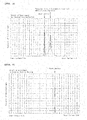
- FIGURE 5 shows an actual result of the measurement conducted with a commercially available laser displacement gauge.
- two peaks are observed, wherein the peak at the inner surface side corresponds to the peak of the light reflected by inner surface, and the peak at the outer surface corresponds to the peak of the light reflected by interface.
- the peak due to the reflected light from the interface between the transparent layer 13 and the bubble containing layer 15 is also detected clearly. Conventionally, interface had not been confirmed by such method, and thus this result is remarkably novel.
- the internal ranging section 17 is moved closer to the inner surface, or the internal ranging section 17 is tilted to alter the outgoing direction of the laser light, so as to search a position and an angle which allows the observation of two peaks.
- the light reflected by inner surface may be observed at a certain position and an angle, and then the light reflected by interface may be observed at a different position and an angle.
- the maximum proximity position is set, thereby preventing the internal ranging section 17 from coming close to the inner surface from such position even when the peak is not observed.
- the inner surface is bent, and thus it is not easy to appropriately set the position and the direction of the internal ranging section 17.
- the three-dimensional shape of the inner surface of the crucible is measured beforehand, and then the internal ranging section 17 is moved in accordance with the three-dimensional shape. Therefore, as shown in FIGURE 4 , it is easy to set the position and the direction of the internal ranging section 17 appropriately. The same can be said with the external ranging section 19.
- the internal ranging section thus detects the reflected light from this bubble, and thus there are cases where the interface between the transparent layer 13 and the bubble containing layer 15 cannot be detected appropriately. Therefore, in a case where the position of the interface measured at a particular measuring point A shifts largely (exceeding a predetermined standard value) from the position of the interface measured at the measuring points before and after the measuring point A, the data obtained for the measuring point A may be eliminated. In such cases, the measurement may be conducted again at a position slightly shifted from the measuring point A, and the data obtained as such may be used.
- the laser light emitted from the emitting section 19a of the external ranging section 19 is reflected at the surface of the outer surface (bubble containing layer 15), the reflected light (light reflected by outer surface) strikes the detecting section 19b, and thus the reflected light is detected.
- the distance between the external ranging section 19 and the outer surface is determined in accordance with the position of detection at the detecting section 19b.
- FIGURE 6 shows the actual result of the measurement conducted with a commercially available laser displacement gauge. As shown in FIGURE 6 , only one peak is observed.
- the external ranging section 19 is moved closer to the inner surface, or the external ranging section 19 is tilted to alter the outgoing direction of the laser light, so as to search a position and an angle which allows the observation of the peak.
- the coordination data of the three-dimensional shape of the inner surface, the interface, and the outer surface may be outputted.
- the data format is not particularly limited, and may be data of text format such as CSV, or may be data of one of the various CAD formats.
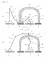
- FIGURES 7(a) and 4b ) each show a shape of a crucible having minimum thickness and a shape of a crucible having a maximum thickness that satisfy the dimension tolerance for the original design, respectively. Since the dimension tolerance for the sidewall portion 11a, the corner portion 11b, and the bottom portion 11c are different from each other, their boundary is discontinuous.
- the shape of the crucible 11 determined from the three-dimensional shape of the inner surface of the crucible 11 and the three-dimensional shape of the outer surface determined from the above-described method are within the shape of the crucible having minimum thickness satisfying the dimension tolerance shown in FIGURE 7 (a) and the shape of the crucible having maximum thickness satisfying the dimension tolerance shown in FIGURE 7(b) , the shape of the crucible 11 satisfies the dimension tolerance. In such case, the shape inspection test is passed. On the other hand, when at least a part of the shape of the crucible 11 determined is not within the shape of FIGURE 7(a) or FIGURE 7(b) , the shape inspection test is not passed. By this method, crucibles having shapes that are out of the tolerance zone can be prevented from being shipped.
- the internal robot arm 5 and the external robot arm 7 can be equipped with a probe for measuring various physical properties. By moving the probe along the three-dimensional shape of the inner surface or the three-dimensional shape of the outer surface of the crucible 11, three-dimensional distribution of various physical properties can be determined.
- the internal robot arm 5 and the external robot arm 7 may be equipped with a plurality of kinds of probes to measure a plurality of physical properties simultaneously, or the probe may be appropriately changed to the plurality of physical properties. In addition, the probes may be changed manually or may be changed automatically using an auto-changer.
- the afore-mentioned internal ranging section 17, the external ranging section 19, and the various probes described later are connected with an external processor having a database function, and can be structured so that the measurement data is taken into the database immediately after the measurement.
- judgment on PASSED / NOT PASSED can be for the various shapes and the physical properties, and thus quality inspection of the crucible can be conducted easily.
- measurement was conducted by mounting the crucible 11 on the rotating table 9.
- measurement may be conducted while the crucible 11 is hold by a robot arm for conveyance 6. Detailed description will be given hereinafter.
- the crucible as a measuring object is mounted on a mounting table 43 with its opening portion facing downwards.
- a robot arm for conveyance 6 is placed on a setting table 41.
- the robot arm for conveyance 6 is preferably a six-axis articulated robot, comprising a plurality of arms 6a, a plurality of joints 6b rotatably supporting the arm 6a, and a main body section 6c.
- An external terminal (not shown) is provided to the main body section 6c, to enable the main body section 6c to exchange data with an external device.
- the tip of the robot arm for conveyance 6 is provided with a holding section 49 to hold the crucible 11.
- the holding section 49 comprises a base 45 and at least four arms 47 extending from the base 45.
- the four arms 47 are arranged with an interval of 90 degrees in the circumferential direction.
- the arms 47 can be moved toward the center in the direction of the radius of the crucible 11, that is, in the direction shown with the arrow X in FIGURE 8(a) .
- the arms 47 are pressed against the sides of the crucible 11 with the holding section 49 in a state where the crucible 11 is positioned within the four arms 47.
- the outer side of the crucible 11 is the bubble containing layer 15, and its surface is rough.
- An elastic member 48 such as urethane rubber is provided on the surface of the arms 47 at the side of the crucible 11.
- the holding section 49 holds the crucible 11 steadily by the friction between the elastic member 48 and the side surface of the crucible 11.
- the pressure being applied to the crucible from the arms 47 is controlled within an appropriate value by using a pressure sensor and the like.
- FIGURE 8(b) shows a state in which the holding section 49 is holding the crucible 11. From this state, the robot arm for conveyance a picks up the crucible 11, and then conveys the crucible 11 to the measuring area placed with the internal robot arm 5.
- the external robot arm 7 may be placed in the measuring area.
- the robot arm for conveyance 6 holds the crucible within the measuring area, and, in such state, the internal robot arm 5 moves the internal ranging section 17 and the various probes along the inner surface of the crucible 11 to carry out the measurement.
- Measurement for a particular position of the crucible 11 with respect to the circumferential direction of the crucible 11 is carried out by moving the internal ranging section 17 between the bottom, portion 11c and the opening portion of the crucible 11. Subsequently, the robot arm for conveyance 6 rotates the crucible 11 in the circumferential direction (the direction of the arrow Y shown in FIGURE 8(c) ). Then, the measurement is carried out again by moving the internal ranging section 17 between the bottom portion 11c and the opening portion of the crucible 11. Accordingly, the measurement can be carried out for the entire inner circumference surface by repeating the rotation of the crucible 11 and the measurement.
- the rotation angle of the rotation after each of the measurement is, 2-10 degrees for example, preferably 6.3 degrees or less.
- the difference in the sum length of the sides of the polygonal structured by connecting each of the measuring points in the circumferential direction with respect to the circumferential length of the perfect circle is 1% or less, and thus sufficient precision can be achieved.
- the afore-described measurement of the three-dimensional shape conducted by fogging the crucible may be carried out at a different place before mounting the crucible 11 on the mounting table 43, carried out on the mounting table 43, carried out in the measuring area, or may be carried out in a different measuring area provided in the moving area of the robot arm for conveyance 6.
- Measurement of three-dimensional shape of the vitreous silica crucible was studied by using a three-dimensional shape measuring device which measures the three-dimensional shape by measuring the reflected light from a measuring object irradiated with a pattern light.
- the shape of the crucible was not detected.
- the measurement was carried out in a condition where the surface of the crucible was fogged by allowing the cooled crucible to stand in atmosphere, the shape of the inner surface of the crucible was measured.
Landscapes
- Chemical & Material Sciences (AREA)
- Engineering & Computer Science (AREA)
- Materials Engineering (AREA)
- Organic Chemistry (AREA)
- Crystallography & Structural Chemistry (AREA)
- Metallurgy (AREA)
- Physics & Mathematics (AREA)
- General Physics & Mathematics (AREA)
- Manufacturing & Machinery (AREA)
- Crystals, And After-Treatments Of Crystals (AREA)
Abstract
Description
- The present invention relates to a method for measuring a three-dimensional shape of a vitreous silica crucible, and to a manufacturing method of a monocrystalline silicon.
- A monocrystalline silicon has been manufactured by the Czochralski method (the CZ method) using a vitreous silica crucible. In particular, a silicon melt obtained by melting polycrystalline silicon raw material is retained in the vitreous silica crucible, and then the silicon melt is allowed to come in contact with a seed crystal of a monocrystalline silicon, followed by gradual pulling of the seed crystal while rotating the seed crystal. Thus, the monocrystalline silicon is manufactured by allowing the single crystal to grow with the seed crystal acting as a core. The softening point of the vitreous silica is approximately 1200 to 1300°C, while the pulling temperature of the monocrystalline silicon is 1450 to 1500°C, which is an extremely high temperature above the softening point of the monocrystalline silicon. In addition, the time required for the pulling may exceed two weeks.
- The monocrystalline silicon being pulled is required to have a purity of 99.999999999% or higher, and thus the vitreous silica crucible used for the pulling is also required to have high purity.
- The diameter size of the vitreous silica crucible varies as 28 inches (approximately 71cm), 32 inches ((approximately 81cm), 36 inches (approximately 91cm), 40 inches (approximately 101cm), and the like. The crucible with the diameter of 101cm is huge, with its weight being approximately 120kg. The weight of the silicon melt being retained therein is 900kg or more. Accordingly, when pulling the monocrystalline silicon, 900kg or more of the silicone melt at approximately 1500°C is retained in the crucible.
- One example of the manufacturing method of such vitreous silica crucible includes a silica powder layer forming step to form a silica powder layer by depositing the silica powder having an average particle diameter of approximately 300µm onto the inner surface of a rotating mold; an arc fusing step to form a vitreous silica layer by arc fusing the silica powder layer while depressurizing the silica powder layer from the mold side (hereinafter referred to as a "rotating mold method").
- During the early stage of the arc fusing step, the silica powder layer is strongly depressurized, thereby removing bubbles to form a transparent vitreous silica layer (hereinafter referred to as "transparent laser"). Then, the degree of depressurizing is weakened to form a bubble containing vitreous silica layer (hereinafter referred to as "bubble containing layer"), with remaining bubbles. Accordingly, a vitreous silica crucible having a two-layer structure, with the transparent layer at the inner surface side and the bubble containing layer at the outer surface side, can be formed.
- As the silica powder used for the manufacture of the crucible, natural silica powder manufactured by pulverizing natural quartz, and synthetic silica powder manufactured by chemical synthesis can be mentioned. Here, physical property, shape, and size of natural silica powder tend to vary since the raw material of the natural silica powder is a natural product. When the physical property, shape, or size varies, the fused state of the silica powder varies, and thus the three-dimensional shape of the crucible being manufactured would vary even when the arc fusing is conducted under the conditions.
- In order to conduct the arc fusing with an intent to suppress such variation, or to conduct the pulling of the monocrystalline silicon by taking such variation in consideration, it is necessary to understand the three-dimensional shape of all crucibles.
- As a method for measuring the three-dimensional shape, a light section method in which an object to be measured is irradiated with a slit light, and a pattern projection method in which the object to be measured is irradiated with a pattern light, are disclosed as conventional techniques in Patent Document 1.
- Here, when measuring the three-dimensional shape by the light irradiation method, the data of the three-dimensional shape for the object to be measured is obtained by receiving the reflected light reflected by the object to be measured, and then analyzing the data of the reflected light. Therefore, it is important to receive the appropriate reflected light. However, when the object to be measured is a transparent body such as a vitreous silica crucible for example, the three-dimensional shape may not be measured properly due to the internal scattering light.
- Therefore, when measuring a transparent body, a reflecting material such as white powder and the like was applied onto its surface to suppress the generation of internal scattering light.
- Patent Document 1:
JP-A-2008-281399 - When the three-dimensional shape of the inner surface of the vitreous silica crucible was measured by the conventional method, the reflecting material need be applied onto the inner surface of the crucible. However, when the reflecting material was applied onto the inner surface of the crucible, the reflecting material may contaminate the inner surface, or the reflecting material may remain on the surface. In such cases, it may cause an adverse effect on the manufacturing yield of the monocrystalline silicon. Therefore, the method of applying the reflecting material cannot be used for measuring the three-dimensional shape of the inner surface of the crucible.
- The present invention has been made in view of such circumstances, and provides a method for measuring a three-dimensional shape of a vitreous silica crucible, which enables to measure the three-dimensional shape of the inner surface of the crucible without contaminating the inner surface of the crucible.
- According to the present invention, a method for measuring a three-dimensional shape of a vitreous silica crucible, comprising the steps of:
- forming a fog onto an inner surface of the vitreous silica crucible,
- measuring a three-dimensional shape of the inner surface, by measuring a reflected light from the inner surface irradiated with light,
is provided. - The present inventors have investigated the method which enables the measurement of the three-dimensional shape of the inner surface of the crucible without contaminating the inner surface of the crucible. The inventors got an idea to achieve the measurement of the three-dimensional shape of the inner surface from the fact that when the crucible was white with fog, the light was irregularly reflected at the inner surface of the crucible, thereby allowing appropriate detection of the diffused reflected light. Actually, experimentation carried out by using a commercially available three-dimensional shape measuring machine revealed that when there was no fog on the surface, the reflected light from the inner surface of the crucible was not appropriately detected, thereby making it impossible to measure the three-dimensional shape, however, when the crucible was thoroughly cooled in a refrigerator and then placed in a room at ambient temperature, allowing fog to generate on the surface, the measurement carried out with the crucible with fog succeeded in the detection of the reflected light from the inner surface of the crucible. Accordingly, measurement of the three-dimensional shape of the inner surface of the crucible was achieved.
- Since the component of the fog on the crucible is water vapor in the air, the fog and the moisture can be removed from the surface of the crucible by merely heating or drying the crucible. Therefore, the inner surface of the crucible is not contaminated.
- Further, the superior point of the present invention is that the three-dimensional shape of the actual product can be obtained, since the three-dimensional shape of the entire inner surface of the crucible can be determined in a non-destructive manner. In the conventional method, the crucible was cut to prepare a sample, and the three-dimensional shape of this sample was measured. Accordingly, the conventional method was problematic in that the data cannot be obtained for the actual product, and the preparation of the sample required time and cost. Therefore, the present invention is advantageous since the three-dimensional shape of the actual product can be measured at low cost. In addition, the present invention is especially advantageous for huge crucibles with an outer diameter of 28 inches or more, and extra-huge crucibles with an outer diameter of 40 inches or more. This is since the time and cost required for preparing samples for these crucibles would be extremely long and high respectively, when compared with those for the small crucibles.
- Further, the present invention is advantageous in that the three-dimensional shape of the inner surface of the crucible can be measured in a contactless manner. As described, manufacture of a monocrystalline silicon with extremely high purity of 99.999999999% or higher requires the inner surface of the crucible to be kept at high cleanliness. While the inner surface of the crucible gets easily contaminated in the contact process, the contactless process of the present invention can prevent the inner surface from getting contaminated.
- Therefore, according to the present invention, the three-dimensional shape of the inner surface of the crucible can be measured without contaminating the inner surface of the crucible.
- The present invention enables the measurement of the three-dimensional shape of a transparent body by a very simple method which makes the transparent body substantially a non-transparent body. Therefore, the present invention can be applied to methods for measuring three-dimensional shapes, which utilize various light irradiation methods.
- The shape of the inner surface of the crucible directly affects the manufacturing yield of the monocrystalline silicon, and thus it is necessary to measure the shape precisely. However, there are cases where the precision of the three-dimensional shape measured by the afore-mentioned method is not sufficient as the shape of the inner surface of the crucible.
- Accordingly, the present invention preferably comprises the steps of:
- moving an internal ranging section along an inner surface of the vitreous silica crucible in a contactless manner in accordance with the three-dimensional shape;
- measuring a distance between the internal ranging section and the inner surface as a distance from the inner surface, by subjecting the inner surface of the crucible to irradiation with laser light and then detecting a reflected light from the inner surface, the laser light being emitted from the internal ranging section in an oblique direction with respect to the inner surface, and the measurement being conducted at a plurality of measuring points along a course of a movement of the internal ranging section; and
- obtaining a three-dimensional shape of the inner surface of the crucible, by associating three-dimensional coordinates of each of the measuring points with the distance from the inner surface.
- The inventors of the present invention have found that when the laser light was emitted in an oblique direction with respect to the inner surface of the crucible, the reflected light from the inner surface of the crucible (light reflected by inner surface) can be detected.
- Then, the light reflected by inner surface is detected by a different position of a detecting unit of the internal ranging section in accordance with the distance between the internal ranging section and the inner surface. This allows the measurement of the distance from inner surface, which is the distance between the internal ranging section and the inner surface, in accordance with the triangulation principle.
- In addition, by carrying out the measurement at a plurality of measuring points along the inner surface of the crucible, the coordinates of the internal ranging section can be associated with the distance from inner surface to obtain the coordinates of the inner surface of the crucible that correspond to each of the measuring points.
- Accordingly, by carrying out the measurement for each of the plurality of measuring points arranged as a mesh with 2mm distance for example, coordinates of the inner surface can be obtained as a mesh. Thus, the three-dimensional shape of the inner surface of the crucible can be obtained.
- This method is advantageous since the sampling rate of the data is very high. When a preliminary experiment was carried out for a crucible having a diameter of 1m and 100,000 measuring points, the three-dimensional shape of the entire inner surface was measured in about 10 minutes.
- The internal ranging section emits laser light towards the inner surface, and detects its reflected light in order to measure the distance, however, accurate measurement requires a certain level of accurate knowledge of the distance between the internal ranging section and the inner surface, and the incident angle of the laser light towards the inner surface. Therefore, regarding the bent portions such as the corner portions of the crucible, it was difficult to set the distance and the direction of the internal ranging section with respect to the inner surface. In contrast, in the present invention, the three-dimensional shape of the inner surface is obtained in advance, and the internal ranging section is moved in accordance with the three-dimensional shape. Therefore, the distance and the direction of the internal ranging section with respect to the inner surface can be set appropriately.
- Here, concerning the manufacture of a huge monocrystalline silicon ingot having a diameter of 200 to 450mm (for example, 200mm, 300mm, 450mm) and a length of 2m or more, a vitreous silica crucible is preferably used. The monocrystalline silicon wafer manufactured from such huge ingot is used preferably for the manufacture of flash memory or DRAM.
- The price of the flash memories and DRAM are dropping rapidly, and thus it is necessary to manufacture the huge monocrystalline silicon ingot with high quality at low cost. For this purpose, the huge crucible need be manufactured with high quality at low cost.
- In addition, processes using wafers having a diameter of 300mm are the mainstream, and processes using wafers having a diameter of 450mm are now under development. Therefore, in order to stably manufacture wafers having a diameter of 450mm, demand for huge crucibles with high quality is increasing.
- In the present invention, the three-dimensional shape of the inner surface of the crucible is measured for its entire circumference. Therefore, according to the present invention, determination of whether the shape of the inner surface of the crucible manufactured is identical with its specifications can be made easily. Then, when the shape of the inner surface does not meet the specifications, the manufacturing conditions such as the arc fusing conditions can be altered. Accordingly, crucibles with high quality, of which shape of the inner surface being identical with the specifications, can be manufactured with high manufacturing yield.
- In addition, if the three-dimensional shape of the inner surface can be obtained accurately, various measuring devices such as a camera, a microscope, a probe for measuring infrared absorption spectrum, a probe for measuring Raman spectrum and the like can be moved along the inner surface of the crucible for measurement, thereby allowing to obtain a three-dimensional distribution of various physical properties of the inner surface of the crucible. Conventionally, samples were cut out from the crucible to measure the various physical properties, however, such procedure cannot achieve a non-destructive measurement nor inspection for all crucibles. Therefore, improvement in the quality of the crucible was not accomplished. In the present invention, various physical properties can be measured by a non-destructive measurement for all of the crucibles. Therefore, when an odd data is obtained, investigation can be conducted right away, and its cause can be investigated easily. As described, the present invention has a technical significance in that non-destructive measurement can be conducted for all of the crucibles, which was impossible with the conventional techniques.
- It is preferable to carry out the measurement of the three-dimensional shape and the measurement of the three-dimensional distribution of the various physical properties of the inner surface, by moving a tip of a robot arm along the inner surface of the crucible and thus carrying out the measurement at a plurality of points during its movement. The advantage of this method is that the coordinates of the measuring points can be obtained. If an operator moves the probe and carries out the measurement, accurate coordinates of the points of measurement cannot be obtained, and thus it is impossible to accurately understand to which of the measuring points does each of the measured value corresponds. If the robot arm is used, accurate coordinate can be obtained, and thus the obtained data can be more utilized.
- The larger the crucible becomes, the more difficult its manufacture becomes. This phenomena can be easily understood when the difficulty of baking a pancake having a diameter of 50cm and a thickness of 5cm is compared with the easiness of baking a pancake having a diameter of 10cm and a thickness of 1cm. The difficulty of the former is extremely high. Pancakes of large size easily get burnt on its surface, or become under-cooked in the inside. In a similar manner, heat management during the manufacture of the huge crucible is more difficult than that for the small crucible. This leads to variation in the shape of the inner surface and the physical properties of the inner surface. Therefore, the necessity of measuring the three-dimensional shape of the inner surface and the three-dimensional distribution of the physical properties by using the method of the present invention is especially high for huge crucible.
- In addition, when the monocrystalline silicon is pulled, the silicon melt is heated with a carbon heater and the like provided around the crucible in order to maintain the temperature of the silicon melt retained in the crucible at a high temperature of 1450 to 1500°C. When the crucible becomes huge, the distance between the carbon heater and the center of the crucible becomes long (when the radius of the crucible enlarges from 25cm to 50cm, the distance between the carbon heater and the center of the crucible is approximately doubled). Accordingly, in order to maintain the temperature of the silicon melt at the center of the crucible at a temperature higher than the melting point of silicon, the quantity of heat applied to the silicon melt from the carbon heater via the crucible becomes large. Therefore, when the crucible becomes huge, the quantity of heat applied to the crucible also becomes large, and thus problems such as the deformation of the crucible arise. Thus, the variation in the shape of the crucible and the physical properties of the inner surface arise problems when the monocrystalline silicon is pulled. This problem is seen more with huge crucibles than with small crucibles. Therefore, the necessity of measuring the three-dimensional shape of the inner surface and the three-dimensional distribution of the physical properties by using the method of the present invention is especially high with huge crucibles.
- Here, since the weight of huge crucibles are 38kg or more (for example, crucibles having a diameter of 71cm weigh 39kg, crucibles having a diameter of 81cm weigh 59kg, crucibles having a diameter of 91cm weigh 77kg, crucibles having a diameter of 101cm weigh 121kg), it is very difficult to handle them by man hand. In addition, in order to measure the three-dimensional shape of the inner surface around the crucible, it is necessary to rotate the crucible. However, it is difficult to rotate the crucible with man hand, and to obtain the rotation angle accurately when rotated with man hand. Accordingly, the present inventors have thought of holding the crucible with a robot arm for conveyance, and to carry out the measuring while holding. By using the robot arm for conveyance, heavy and fragile crucible can be conveyed easily and safely, and the crucible can be set at an accurate position of a measurement area. In addition, the crucible can be accurately rotated by 5 degrees for example, and thus the three-dimensional shape of the inner surface and the three-dimensional distribution of the physical properties can be measured accurately.
- The area of the inner surface of the crucible is 14,400cm2 for the crucible having a diameter of 81cm, 16,640cm2 for the crucible having a diameter of 91cm, and 21,109cm2 for the crucible having a diameter of 101cm. An image of the inner surface can be taken by moving the tip of an internal robot arm along the inner surface of the crucible. Here, if the size of an image is 4cm x 4cm, the number of the images when the image of the entire inner surface is taken would be approximately 900 images for the crucible having a diameter of 81cm, 1,000 images for the crucible having a diameter of 91cm, and 1,300 images for the crucible having a diameter of 101cm. Such number of images would be required for each of the crucibles. However, when the method of the present invention is used, images are taken by cooperating the internal robot and the robot arm for conveyance, and thus such a large number of images can be taken in comparatively short time.
- Preferably, the crucible comprises a transparent vitreous silica layer at an inner surface side, and a bubble containing layer at an outer surface side, and
the internal ranging section detects light reflected by interface, the interface being an interface between the transparent vitreous silica layer and the bubble containing layer, and measures a distance between the internal ranging section and an interface as a distance from interface;
and the method for measuring the three-dimensional shape of the vitreous silica crucible further comprises a step of: - obtaining a three-dimensional shape of the interface by associating three-dimensional coordinates of each of the measuring points with the distance from interface.
- The present inventors have found that when the laser light was emitted in an oblique direction with respect to the inner surface of the crucible, the reflected light from the interface between the transparent layer and the bubble containing layer (light reflected by interface) was detected in addition to the reflected light from the inner surface of the crucible (light reflected by inner surface). Here, the interface between the transparent layer and the bubble containing layer is a plane where the bubble content rate changes dramatically, however, such interface is not as distinct as the interface between air and glass. Therefore, the finding that the light reflected from the interface between the transparent layer and the bubble containing layer can be detected was very surprising.
- Then, the light reflected by inner surface and the light reflected by interface are detected by a different position of a detecting unit of the internal ranging section. This allows the measurement of the distance from inner surface, which is the distance between the internal ranging section and the inner surface, and the distance from interface, which is the distance between the internal ranging section and the interface, in accordance with the triangulation principle.
- In addition, by carrying out the measurement at a plurality of measuring points along the inner surface of the crucible, the coordinates of the internal ranging section can be associated with the distance from inner surface and the distance from interface to obtain the coordinates of the inner surface of the crucible and the coordinates of the interface of the crucible that correspond to each of the measuring points.
- Accordingly, by carrying out the measurement for each of the plurality of measuring points arranged as a mesh with 2 mm distance for example, coordinates of the inner surface and the coordinates of the interface can be obtained as a mesh. Thus, the three-dimensional shape of the inner surface and the interface of the crucible can be obtained. In addition, by calculating the distance between the inner surface and the interface, the thickness of the transparent layer can be calculated for arbitrary positions. Therefore, the three-dimensional distribution of the thickness of the transparent layer can be obtained.
-
-
FIGURE 1 is an explanatory drawing of a vitreous silica crucible according to an embodiment of the present invention. -
FIGURE 2 is an explanatory drawing of a method for measuring a three-dimensional shape of a vitreous silica crucible. -
FIGURE 3 is an explanatory drawing of a method for measuring a precise three-dimensional shape of a vitreous silica crucible. -
FIGURE 4 is an enlarged view of the vitreous silica crucible ofFIGURE 3 , amplifying the internal ranging section and its vicinity. -
FIGURE 5 shows a result of the measurement carried out with the internal ranging section ofFIGURE 3 . -
FIGURE 6 shows a result of the measurement carried out with the external ranging section ofFIGURE 3 . -
FIGURES 7(a) and 7(b) are each showing a shape of a crucible having minimum thickness and maximum thickness satisfying the dimension tolerance, respectively. -
FIGURES 8(a), 8(b) and 8(c) are explanatory drawings for a method to carry out the measurement while the crucible is held by the robot arm for conveyance, - Hereinafter, the method for measuring the three-dimensional shape of the vitreous silica crucible according to the present embodiment will be described with reference to the figures.
- Hereinafter, the
vitreous silica crucible 11 used in the present embodiment will be described with reference toFIGURE 1 . Thecrucible 11 is, in one example, manufactured by a method comprising a silica powder layer forming step to form a silica powder layer by depositing the silica powder having an average particle diameter of approximately 300µm onto the inner surface of a rotating mold; an arc fusing step to form a vitreous silica layer by arc fusing the silica powder layer while depressurizing the silica powder layer from the mold side (hereinafter referred to as a "rotating mold method"). - During the early stage of the arc fusing step, the silica powder layer is strongly depressurized, thereby removing bubbles to form a transparent vitreous silica layer (hereinafter referred to as "transparent layer") 13. Then, the degree of depressurization is weakened to form a bubble containing vitreous silica layer (hereinafter referred to as "bubble containing layer") 15, with remaining bubbles. Accordingly, a vitreous silica crucible having a two-layer structure, with the
transparent layer 13 at the inner surface side and thebubble containing layer 15 at the outer surface side can be formed. - As the silica powder used for the manufacture of the crucible, natural Silica powder manufactured by pulverizing natural quartz, and synthetic silica powder manufactured by chemical synthesis can be mentioned. Here, physical property, shape, and size of natural silica powder tend to vary since the raw material of the natural silica powder is a natural product. When the physical property, shape, or size varies, the fused state of the silica powder varies, and thus the three-dimensional shape of the inner surface of the crucible being manufactured would vary among the crucibles, even when the arc fusing is conducted under the same conditions. Therefore, the three-dimensional shape of the inner surface need be measured for each one of the manufactured crucibles.
- The
vitreous silica crucible 11 comprises acylindrical sidewall portion 11a, acurved bottom portion 11c, and acorner portion 11b connecting thesidewall portion 11a and thebottom portion 11c, the curvature of thecorner portion 11b being larger than that of thebottom portion 11c. In the present invention, thecorner portion 11b is a portion where thesidewall portion 11a and thebottom portion 11c are linked, and starts from the point where the tangential line of the curve of the corner portion falls on thesidewall portion 11a of the vitreous silica crucible, to the point where the tangential line of the corner portion and the tangential line of thebottom portion 11c becomes the common tangent. In other words, the point where thesidewall portion 11a of thevitreous silica crucible 11 starts to bend is the boundary between thesidewall portion 11a and the corner portion b. Further, the portion of the bottom of the crucible where the curvature is constant is thebottom portion 11c, and the point where the curvature starts to change as the distance from the center of the bottom of the crucible increases is the boundary between thebottom portion 11c and thecorner portion 11b. - The
crucible 11 as manufactured by the aforedescribed method has a transparent body, and thus the reflected light was not detectable with the contactless method for measuring three-dimensional shape which and the conventional light irradiation procedure. Accordingly, it was difficult to measure the three-dimensional shape. Therefore, in the present embodiment, a fog is formed on the inner surface of the crucible before carrying out the measurement of the three-dimensional shape, and the inner surface in a whitish condition is irradiated with a light for measuring the shape. When the inner surface is in a condition without fog being formed thereon, the light reflected by the surface from the inner surface of the crucible and the internally scattered light from the inside of the crucible would be superimposed, and thus accurate measurement of the three-dimensional shape is difficult. On the other hand, when the inner surface is in the condition with a fog being formed thereon, a large portion of the light for measurement would be scattered at the surface, and would hardly go inside the crucible. Therefore, effect of the internally scattered light can be eliminated, and thus accurate measurement of the three-dimensional shape is enabled. - In the present specification, "fog" refers to a phenomenon similar to that observed with window glasses getting whitish in winter. When an atmosphere around a cold object is cooled, water vapor contained in the atmosphere is condensed to form minute particles. Then a large number of these minute particles adhere onto the surface of the object, making the surface whitish.
- Fog is formed when the temperature of the atmosphere at the surface of the object becomes lower than its dew point. Here, dew point becomes higher as the amount of water vapor contained in the surrounding atmosphere increases. Therefore, in order to promote the formation of fog, the object should be cooled, or the amount of water vapor contained in the surrounding atmosphere should be increased. The water used for increasing the amount of water vapor is preferably the ultra pure water used in the manufacture of semiconductors and the like. In such case, the cleanliness of the inner surface of the crucible can be maintained at an extremely high level.
- Therefore, in order to form a fog onto the inner surface of the
crucible 11, thecrucible 11 sufficiently cooled in a refrigerated room may be brought into a measuring room at ambient temperature, or thecrucible 11 placed in the measuring room may be allowed to come in contact with a coolant to cool thecrucible 11. Otherwise, in another method, the temperature of the measuring room may be set comparatively low, and then the amount of water vapor contained in the atmosphere in the measuring room may be increased using a humidifier (ultrasonic type, thermal type, and the like) to form the fog on thecrucible 11. The method for cooling thecrucible 11 itself and the method for increasing the amount of water vapor contained in the measuring room may be used in combination. In addition, when thecrucible 11 is mounted with its opening portion facing downward, the replacement of the atmosphere inside and the outside thecrucible 11 becomes less. If the water vapor is supplied inside thecrucible 11 is such condition, the amount of water vapor contained in the atmosphere contacting the inner surface of thecrucible 11 can be increased easily. - The fog on the surface of the
crucible 11 is faint at first. In such condition, the effect of the internally scattered light cannot be eliminated sufficiently, and thus appropriate measurement of the three-dimensional shape cannot be performed. As time passes, the whiteness increases gradually, and then reaches a condition in which the water minute particles are uniformly dispersed and adhered on the surface. This is the condition appropriate for measuring the three-dimensional shape. When time passes further, the amount of water adhered to the surface increases, allowing neighboring water minute particles to come into contact and aggregate. Then, the aggregated water drops would fall due to gravity and thus aggregation further progresses. Appropriate measurement of the three-dimensional shape cannot be performed in this condition, either. Therefore, the measurement of the three-dimensional shape need be conducted at an appropriate timing. Accordingly, it is preferable to first achieve the conditions for forming the fog onto thecrucible 11, and then carry out the measurement of the three-dimensional shape for several times within a predetermined interval. By such procedure, measurement of the three-dimensional shape can be carried out with an appropriate fogging condition. - Here, an example of the measurement of the three-dimensional shape of the inner surface of the crucible according to the present embodiment will be explained with reference to
FIGURE 2 . - The
vitreous silica crucible 11 as a measuring object is mounted on the rotatable rotating table 9 with its opening portion facing downwards. Thecrucible 11 may be placed on the rotating table 9 immediately after being taken out from a refrigerating room not shown, or the rotating table 9 may have a cooling function to cool thecrucible 11. In either way, a crucible at a temperature lower than the surrounding temperature is placed on the rotating table 9. Water vapor is supplied into the internal space of thecrucible 11 from the openingportion 12 provided between the base 1 and the rotating table 9. Accordingly, the water vapor contained in the atmosphere of the internal space of thecrucible 11 is increased, and the inner surface of thecrucible 11 can easily be fogged. - A robot arm 4 is arranged on the base 1, the base 1 being arranged at a position covered with the crucible The robot arm 4 comprises an
arm 4a, a joint 4b to rotatably support thearm 4a, and amain body section 4c. An external terminal (not shown) is provided to themain body section 4c, to enable themain body section 4c to exchange data with an external device. The tip of the robot arm 4 is provided with a three-dimensionalshape measuring section 51 to measure the three-dimensional shape of the inner surface of thecrucible 11. The inner surface of thecrucible 11 is irradiated with a measuring light from the three-dimensionalshape measuring section 51, while the inner surface of thecrucible 11 is in a fogged condition. Then, the reflected light from the inner surface is detected, and thus the three-dimensional shape of the inner surface of thecrucible 11 is measured. A controlling section to control the joint 4b and the three-dimensionalshape measuring section 51 is provided inside themain body section 4c. The controlling section moves thearm 4a by rotating the joint 4b in accordance with a program installed in themain body section 4c or with an external input signal, thereby changing the direction of the measuring light 8 emitted from the three-dimensionalshape measuring section 51. Specifically, for example, the measurement is started from a position near the opening portion of thecrucible 11, and then the three-dimensional measuring section 51 is moved towards thebottom portion 11c of thecrucible 11, to carry out the measurement for a plurality of measuring points along the moving course. - When the measurement from the opening portion to the
bottom portion 11c of the crucible is finished, the rotating table 9 is rotated with a small angle, and a similar measurement is carried out. This measurement may be carried out from thebottom portion 11c towards the opening portion. The rotating angle of the rotating table 9 is determined by taking the accuracy and the measuring time into consideration. When the rotating angle is too large, the accuracy of measurement is insufficient, and when the rotating angle is too small, the measuring time becomes too long. The rotation of the rotating table 9 is controlled in accordance with a stored program or with an external input signal. The rotating angle of the rotating table 9 can be detected with a rotary encoder and the like. - Accordingly, the three-dimensional shape of the entire inner surface of the crucible can be measured. After the three-dimensional shape of the entire inner surface of the crucible is measured, the inner surface of the
crucible 11 can be dried by supplying dry air into the internal space of thecrucible 11. - The three-dimensional shape thus obtained can be utilized in various applications. For example, by comparing the measured three-dimensional shape with the three-dimensional shape of its original design, the variation from the original design can be grasped for each of the crucibles. When the variation exceeds the standard value, the shape of the crucible can be adjusted, or shipment of the crucible can be avoided. Accordingly, the quality of the crucibles being shipped can be improved. In addition, conditions for manufacture (conditions for arc fusing and the like) can be associated with the shape of each of the crucibles, and feedback can be conducted when the shape of the crucible meets the standards. Further, by measuring Roman spectrum, infrared absorption spectrum, surface roughness, bubble content and the like for a plurality of measuring points with respect to the three-dimensional shape of the inner surface of the crucible, the three-dimensional distribution of their measurement value can be obtained. This three-dimensional distribution can be used for the shipping inspection. In addition, the data of the three-dimensional shape and the three-dimensional distribution of the various measurement values with respect to the three-dimensional shape can be used as a parameter for pulling the monocrystalline silicon. Accordingly, the pulling of the monocrystalline silicon can be controlled with higher accuracy.
- Here, the method for measuring the three-dimensional shape of the inner surface of the crucible was described in detail, however, the three-dimensional shape of the outer surface of the crucible can be measured in a similar manner.
- The three-dimensional shape obtained by the afore-mentioned method can be used as a basic data of the three-dimensional shape for measuring precise three-dimensional shape of the inner surface and the interface of the crucible. Hereinafter, the method for measuring the precise three-dimensional shape of the inner surface and the interface will be described in detail.
- Hereinafter, the method for measuring the precise three-dimensional shape of the inner surface of the crucible will be explained with reference to
FIGURES 3 to 6 . In the present embodiment, the internal rangingsection 17 comprising a laser displacement gauge and the like is contactlessly moved along the inner surface of the crucible. For each of the plurality of measuring points along the moving course, the inner surface of the crucible is irradiated with a laser light, the laser light being emitted in an oblique direction with respect to the inner surface. Then, the reflected light is detected to measure the three-dimensional shape of the inner surface of the crucible. Hereinafter, the method will be described in detail. Here, when the shape of the inner surface is being measured, the three-dimensional shape of the interface between thetransparent layer 13 and thebubble containing layer 15 can be measured simultaneously. In addition, the three-dimensional shape of the outer surface of the crucible can be measured by using the external rangingsection 19. These aspects will be also explained. - The
vitreous silica crucible 11 as a measuring object is mounted on the rotatable rotating table 9 with its opening portion facing downwards. Theinternal robot arm 5 is arranged on the base 1, the base 1 being arranged at a position covered with thecrucible 11. Theinternal robot arm 5 is preferably a six-axis articulated robot, comprising a plurality ofarms 5a, a plurality ofjoints 5b rotatably supporting thearm 5a, and amain body section 5c. An external terminal (not shown) is provided to themain body section 5c, to enable themain body section 5c to exchange data with an external device. The tip of theinternal robot arm 5 is provided with a internal rangingsection 17 to measure the shape of the inner surface of thecrucible 11. The inner surface of thecrucible 11 is irradiated with a laser light from the internal rangingsection 17, and the reflected light from the inner surface is detected to measure the distance between the internal rangingsection 17 and the inner surface of thecrucible 11. A controlling section to control thejoints 5b and the internal rangingsection 17 is provided inside themain body section 5c. The controlling section moves thearm 5a by rotating thejoints 5b in accordance with a program installed in themain body section 5c or with an external input signal, thereby moving the internal rangingsection 17 to an arbitrary three-dimensional position. Specifically, the internal rangingsection 17 is contactlessly moved along the inner surface of the crucible. Here, the controlling section is provided with data for the rough shape of the inner surface of the crucible, and the position of the internal rangingsection 17 is moved in accordance with the data. The data for the rough shape is the data obtained for the three-dimensional shape in <2. Method for Measuring Three-dimensional Shape>. Conventionally, it was not easy to appropriately set the distance and the direction of the internal rangingsection 17 with respect to the inner surface, regarding the bent portion such as thecorner portion 11b of the crucible. On the other hand, in the present embodiment, the three-dimensional shape of the inner surface can be obtained in advance, and then the internal ranging section is moved in accordance with the obtained three-dimensional shape. Therefore, the distance and the direction of the internal ranging section with respect to the inner surface can be set appropriately. - More specifically, for example, the measurement is started from a position near the opening portion of the
crucible 11, as shown inFIGURE 3(a) . Then the internal rangingsection 17 is moved towards thebottom portion 11c of thecrucible 11, to carry out the measurement for a plurality of measuring points along the moving course, as shown inFIGURE 3(b) . The interval of the measurement is 1-5 mm for example, and 2 mm for example. The measurement is conducted with the timing pre-stored in the internal rangingsection 17, or in accordance with an external trigger. The results of the measurement are stored in the memory section of the internal rangingsection 17, and are sent all together to themain body section 5c after the measurement is completed, or are sent to themain body section 5c each time after each of the measurement is conducted. The internal rangingsection 17 may be structured so as to be controlled by a controlling section provided individually from themain body section 5c. - When the measurement from the opening portion to the
bottom portion 11c of the crucible is finished, the rotating table 9 is rotated with a small angle, and a similar measurement is conducted. This measurement may be conducted from thebottom portion 11c towards the opening portion. The rotating angle of the rotating table 9 is determined by taking the accuracy and the measuring time into consideration and is 2-10 degrees (preferably 6.3 degrees or less). When the rotating angle is too large, the accuracy of measurement is insufficient, and when the rotating angle is too small, the measuring time becomes too long. The rotation of the rotating table 9 is controlled in accordance with a stored program or with an external input signal. The rotating angle of the rotating table 9 can be detected with a rotary encoder and the like. The rotation of the rotating table 9 is preferably linked with the movement of the internal rangingsection 17 and the external rangingsection 19 described later. By such, the calculation of the three-dimensional coordinates of the internal rangingsection 17 and the external rangingsection 19 becomes easy. - As described later, the internal ranging
section 17 can measure both of the distance from the internal rangingsection 17 to the inner surface (distance from inner surface), and the distance from the internal rangingsection 17 to the interface between thetransparent layer 13 and the bubble containing layer 15 (distance from interface). Since the angle of the joint 5b is known from the rotary encoder and the like provided to the joint 5b, the three-dimensional coordinates and the direction of the internal rangingsection 17 at each of the measuring points are also known. Accordingly, if the distance from inner surface and the distance from interface can be obtained, the three-dimensional coordinates at the inner surface and the three-dimensional coordinates at the interface are known. Then, since the measurement from the opening portion to thebottom portion 11c of thecrucible 11 is conducted for the entire circumference of thecrucible 11, the three-dimensional shape of the inner surface and the three-dimensional shape of the interface of thecrucible 11 are known. In addition, since the distance between the inner surface and the interface is known, the thickness of thetransparent layer 13 is known, and thus the three-dimensional distribution of the thickness of the transparent layer can be obtained. - On the
base 3 provided outside thecrucible 11, theexternal robot arm 7 is arranged. Theexternal robot arm 7 is preferably a six-axis articulated robot, comprising a plurality ofarms 7a, a plurality ofjoints 7b rotatably supporting thearm 7a, and a main body section 7c. An external terminal (not shown) is provided to the main body section 7c, to enable the main body section 7c to exchange data with an external device. The tip of theexternal robot arm 7 is provided with an external rangingsection 19 to measure the shape of the outer surface of thecrucible 11. The outer surface of thecrucible 11 is irradiated with a laser light from the external rangingsection 19, and the reflected light from the outer surface is detected to measure the distance between the external rangingsection 19 and the outer surface of thecrucible 11. A controlling section to control thejoints 7b and the external rangingsection 19 is provided inside the main body section 7c. The controlling section moves thearm 7a by rotating thejoints 7b in accordance with a program installed in the main body section 7c or with an external input signal, thereby moving the external rangingsection 19 to an arbitrary three-dimensional position. Specifically, the external rangingsection 19 is contactlessly moved along the outer surface of the crucible. Here, the controlling section is provided with data for the rough shape of the outer surface of the crucible, and the position of the external rangingsection 19 is moved in accordance with the data. More specifically, for example, the measurement is started from a position near the opening portion of thecrucible 11, as shown inFIGURE 3(a) . Then the external rangingsection 19 is moved towards thebottom portion 11c of thecrucible 11, to conduct the measurement for a plurality of measuring points along the moving course, as shown inFIGURE 3(b) . The interval of the measurement is 1-5 mm for example, and 2 mm for example. The measurement is conducted with the timing pre-stored in the external rangingsection 19, or in accordance with an external trigger. The results of the measurement are stored in the memory section of the external rangingsection 19, and are sent all together to the main body section 7c after the measurement is completed, or are sent to the main body section 7c each time after each of the measurement is conducted. The external rangingsection 19 may be structured so as to be controlled by a controlling section provided individually from the main body section 7c. - The movement of the internal ranging
section 17 and the external rangingsection 19 may be synchronized. However, since the measurement of the shape of the inner surface and the shape of the outer surface are conducted independently, it is not necessary to synchronize their movement. - The external ranging
suction 19 can measure the distance from the external rangingsection 19 to the outer surface (distance from outer surface). Since the angle of the joint 7b is known from the rotary encoder and the like provided to the joint 7b, the three-dimensional coordinates and the direction of the external rangingsection 19 are also known. Accordingly, if the distance from outer surface can be obtained, the three-dimensional coordinates at the outer surface are known. Then, since the measurement from the opening portion to thebottom portion 11c of thecrucible 11 is conducted for the entire circumference of thecrucible 11, the three-dimensional shape of the outer surface of thecrucible 11 is known. - Accordingly, since the three-dimensional shape of the inner surface and the outer surface of the crucible are known, the three-dimensional distribution of the wall thickness can be obtained for the crucible.
- Here, the measurement of the distance by the internal ranging
section 17 and the external rangingsection 19 will be described in detail with reference toFIGURE 4 . - As shown in
FIGURE 4 , the internal rangingsection 17 is arranged at the inner surface side of the crucible 11 (at thetransparent layer 13 side), and the external rangingsection 19 is arranged at the outer surface side of the crucible 11 (at thebubble containing layer 15 side). The internal rangingsection 17 comprises an emittingsection 17a and a detectingsection 17b. The external rangingsection 19 comprises an emittingsection 19a and a detectingsection 19b. The measuring range of the internal rangingsection 17 and the external rangingsection 19 are, depending on the type of the measuring device, generally approximately ± 5-10 mm. Therefore, the distance from the internal rangingsection 17 to the inner surface and the distance from the external rangingsection 19 to the outer surface need be set with some degree of accuracy. In addition, the internal rangingsection 7 and the external rangingsection 19 are each provided with a controlling section and an external terminal not shown. The emittingsections sections - The laser light emitted from the emitting
sections 17a of the internal rangingsection 17 is partially reflected at the inner surface (surface of the transparent layer 13), and is partially reflected at the interface between thetransparent layer 13 and thebubble containing layer 15. These reflected lights (light reflected by inner surface and the light reflected by interface) strike the detectingsection 17b, and are thus detected. As obvious fromFIGURE 4 , the light reflected by inner surface and the light reflected by interface strike different positions of the detectingsection 17b. From this difference in the position, the distance from the internal rangingsection 17 to the inner surface (distance from inner surface) and the distance from the internal rangingsection 17 to the interface (distance from interface) are determined respectively. Preferable angle of incidence θ may differ in accordance with the condition of the inner surface, thickness of thetransparent layer 13, condition of thebubble containing layer 15 and the like. For example, it is 30-60 degrees. -
FIGURE 5 shows an actual result of the measurement conducted with a commercially available laser displacement gauge. As shown inFIGURE 5 , two peaks are observed, wherein the peak at the inner surface side corresponds to the peak of the light reflected by inner surface, and the peak at the outer surface corresponds to the peak of the light reflected by interface. As seen inFIGURE 5 , the peak due to the reflected light from the interface between thetransparent layer 13 and thebubble containing layer 15 is also detected clearly. Conventionally, interface had not been confirmed by such method, and thus this result is remarkably novel. - When the distance from the internal ranging
section 17 to the inner surface is too large, or when the inner surface or the interface is locally oblique, there are cases where not both of the peaks are observed. In such case, it is preferable that the internal rangingsection 17 is moved closer to the inner surface, or the internal rangingsection 17 is tilted to alter the outgoing direction of the laser light, so as to search a position and an angle which allows the observation of two peaks. In addition, even when both of the peaks are not observed at the same time, the light reflected by inner surface may be observed at a certain position and an angle, and then the light reflected by interface may be observed at a different position and an angle. In addition, in order to prevent the internal rangingsection 17 from coming into contact with the inner surface, it is preferable that the maximum proximity position is set, thereby preventing the internal rangingsection 17 from coming close to the inner surface from such position even when the peak is not observed. - Here, at the
corner portion 11b for example, the inner surface is bent, and thus it is not easy to appropriately set the position and the direction of the internal rangingsection 17. However, in the present embodiment, the three-dimensional shape of the inner surface of the crucible is measured beforehand, and then the internal rangingsection 17 is moved in accordance with the three-dimensional shape. Therefore, as shown inFIGURE 4 , it is easy to set the position and the direction of the internal rangingsection 17 appropriately. The same can be said with the external rangingsection 19. - Further, when there is an isolated bubble in the
transparent layer 13, the internal ranging section thus detects the reflected light from this bubble, and thus there are cases where the interface between thetransparent layer 13 and thebubble containing layer 15 cannot be detected appropriately. Therefore, in a case where the position of the interface measured at a particular measuring point A shifts largely (exceeding a predetermined standard value) from the position of the interface measured at the measuring points before and after the measuring point A, the data obtained for the measuring point A may be eliminated. In such cases, the measurement may be conducted again at a position slightly shifted from the measuring point A, and the data obtained as such may be used. - In addition, the laser light emitted from the emitting
section 19a of the external rangingsection 19 is reflected at the surface of the outer surface (bubble containing layer 15), the reflected light (light reflected by outer surface) strikes the detectingsection 19b, and thus the reflected light is detected. The distance between the external rangingsection 19 and the outer surface is determined in accordance with the position of detection at the detectingsection 19b.FIGURE 6 shows the actual result of the measurement conducted with a commercially available laser displacement gauge. As shown inFIGURE 6 , only one peak is observed. In a case where the peak is not observed, it is preferable that the external rangingsection 19 is moved closer to the inner surface, or the external rangingsection 19 is tilted to alter the outgoing direction of the laser light, so as to search a position and an angle which allows the observation of the peak. - The coordination data of the three-dimensional shape of the inner surface, the interface, and the outer surface may be outputted. The data format is not particularly limited, and may be data of text format such as CSV, or may be data of one of the various CAD formats.
-
FIGURES 7(a) and4b ) each show a shape of a crucible having minimum thickness and a shape of a crucible having a maximum thickness that satisfy the dimension tolerance for the original design, respectively. Since the dimension tolerance for thesidewall portion 11a, thecorner portion 11b, and thebottom portion 11c are different from each other, their boundary is discontinuous. When the shape of thecrucible 11 determined from the three-dimensional shape of the inner surface of thecrucible 11 and the three-dimensional shape of the outer surface determined from the above-described method are within the shape of the crucible having minimum thickness satisfying the dimension tolerance shown inFIGURE 7 (a) and the shape of the crucible having maximum thickness satisfying the dimension tolerance shown inFIGURE 7(b) , the shape of thecrucible 11 satisfies the dimension tolerance. In such case, the shape inspection test is passed. On the other hand, when at least a part of the shape of thecrucible 11 determined is not within the shape ofFIGURE 7(a) or FIGURE 7(b) , the shape inspection test is not passed. By this method, crucibles having shapes that are out of the tolerance zone can be prevented from being shipped. - The
internal robot arm 5 and theexternal robot arm 7 can be equipped with a probe for measuring various physical properties. By moving the probe along the three-dimensional shape of the inner surface or the three-dimensional shape of the outer surface of thecrucible 11, three-dimensional distribution of various physical properties can be determined. Theinternal robot arm 5 and theexternal robot arm 7 may be equipped with a plurality of kinds of probes to measure a plurality of physical properties simultaneously, or the probe may be appropriately changed to the plurality of physical properties. In addition, the probes may be changed manually or may be changed automatically using an auto-changer. - Further, the afore-mentioned internal ranging
section 17, the external rangingsection 19, and the various probes described later are connected with an external processor having a database function, and can be structured so that the measurement data is taken into the database immediately after the measurement. Here, at the external processor, judgment on PASSED / NOT PASSED can be for the various shapes and the physical properties, and thus quality inspection of the crucible can be conducted easily. - In the afore-mentioned embodiments explained with reference to
FIGURES 3(a) and 3(b) , measurement was conducted by mounting thecrucible 11 on the rotating table 9. Here, in another embodiment, as shown inFIGURES 8(a)-8(c) , measurement may be conducted while thecrucible 11 is hold by a robot arm for conveyance 6. Detailed description will be given hereinafter. - As shown in
FIGURE 8(a) , the crucible as a measuring object is mounted on a mounting table 43 with its opening portion facing downwards. Near the mounting table 43, a robot arm for conveyance 6 is placed on a setting table 41. The robot arm for conveyance 6 is preferably a six-axis articulated robot, comprising a plurality ofarms 6a, a plurality ofjoints 6b rotatably supporting thearm 6a, and amain body section 6c. An external terminal (not shown) is provided to themain body section 6c, to enable themain body section 6c to exchange data with an external device. The tip of the robot arm for conveyance 6 is provided with a holdingsection 49 to hold thecrucible 11. The holdingsection 49 comprises abase 45 and at least fourarms 47 extending from thebase 45. InFIGURE 8 (a) , the fourarms 47 are arranged with an interval of 90 degrees in the circumferential direction. Thearms 47 can be moved toward the center in the direction of the radius of thecrucible 11, that is, in the direction shown with the arrow X inFIGURE 8(a) . Thearms 47 are pressed against the sides of thecrucible 11 with the holdingsection 49 in a state where thecrucible 11 is positioned within the fourarms 47. The outer side of thecrucible 11 is thebubble containing layer 15, and its surface is rough. Anelastic member 48 such as urethane rubber is provided on the surface of thearms 47 at the side of thecrucible 11. Accordingly, the holdingsection 49 holds thecrucible 11 steadily by the friction between theelastic member 48 and the side surface of thecrucible 11. Here, in order not to destroy the crucible by applying too large pressure to thecrucible 11 with thearm 47, the pressure being applied to the crucible from thearms 47 is controlled within an appropriate value by using a pressure sensor and the like. -
FIGURE 8(b) shows a state in which the holdingsection 49 is holding thecrucible 11. From this state, the robot arm for conveyance a picks up thecrucible 11, and then conveys thecrucible 11 to the measuring area placed with theinternal robot arm 5. Here, although not shown, theexternal robot arm 7 may be placed in the measuring area. - Then, as shown in
FIGURE 8(c) , the robot arm for conveyance 6 holds the crucible within the measuring area, and, in such state, theinternal robot arm 5 moves the internal rangingsection 17 and the various probes along the inner surface of thecrucible 11 to carry out the measurement. - Measurement for a particular position of the
crucible 11 with respect to the circumferential direction of thecrucible 11 is carried out by moving the internal rangingsection 17 between the bottom,portion 11c and the opening portion of thecrucible 11. Subsequently, the robot arm for conveyance 6 rotates thecrucible 11 in the circumferential direction (the direction of the arrow Y shown inFIGURE 8(c) ). Then, the measurement is carried out again by moving the internal rangingsection 17 between thebottom portion 11c and the opening portion of thecrucible 11. Accordingly, the measurement can be carried out for the entire inner circumference surface by repeating the rotation of thecrucible 11 and the measurement. - The rotation angle of the rotation after each of the measurement is, 2-10 degrees for example, preferably 6.3 degrees or less. When the rotation angle is 6.3 degrees or less, the difference in the sum length of the sides of the polygonal structured by connecting each of the measuring points in the circumferential direction with respect to the circumferential length of the perfect circle is 1% or less, and thus sufficient precision can be achieved.
- The afore-described measurement of the three-dimensional shape conducted by fogging the crucible may be carried out at a different place before mounting the
crucible 11 on the mounting table 43, carried out on the mounting table 43, carried out in the measuring area, or may be carried out in a different measuring area provided in the moving area of the robot arm for conveyance 6. - Measurement of three-dimensional shape of the vitreous silica crucible was studied by using a three-dimensional shape measuring device which measures the three-dimensional shape by measuring the reflected light from a measuring object irradiated with a pattern light. When the measurement was carried out in a condition where the crucible was fogless, the shape of the crucible was not detected. On the other hand, when the measurement was carried out in a condition where the surface of the crucible was fogged by allowing the cooled crucible to stand in atmosphere, the shape of the inner surface of the crucible was measured.
Claims (13)
- A method for measuring a three-dimensional shape of a vitreous silica crucible, comprising the steps of:forming a fog onto an inner surface of the vitreous silica crucible,measuring a three-dimensional shape of the inner surface, by measuring a reflected light from the inner surface irradiated with light.
- The method of Claim 1, wherein the fog is formed by cooling the vitreous silica crucible.
- The method of Claim 1 or 2, wherein the fog is formed by increasing an amount of water vapor contained in an atmosphere around the vitreous silica crucible.
- The method of any one of Claims 1 to 3, further comprising the steps of:moving an internal ranging section along an inner surface of the vitreous silica crucible in a contactless manner in accordance with the three-dimensional shape;measuring a distance between the internal ranging section and the inner surface as a distance from the inner surface, by subjecting the inner surface of the crucible to irradiation with laser light and then detecting a reflected light from the inner surface, the laser light being emitted from the internal ranging section in an oblique direction with respect to the inner surface, and the measurement being conducted at a plurality of measuring points along a course of a movement of the internal ranging section; andobtaining an inner surface three-dimensional shape of the crucible, by associating three-dimensional coordinates of each of the measuring points with the distance from the inner surface.
- The method of Claim 4, wherein an angle of incidence of the laser light emitted from the internal ranging section is 30 to 60 degrees with respect to the inner surface.
- The method of Claim 4 or 5, wherein
the crucible comprises a transparent vitreous silica layer at an inner surface side, and a bubble containing layer at an outer surface side, and
the internal ranging section detects light reflected by interface, the interface being an interface between the transparent vitreous silica layer and the bubble containing layer, and measures a distance between the internal ranging section and an interface as a distance from interface;
and further comprising the step of :obtaining an interface three-dimensional shape by associating three-dimensional coordinates of each of the measuring points with the distance from interface. - The method of Claim 6, further comprising a step of:outputting coordinate data of the inner surface three-dimensional shape and the interface three-dimensional shape.
- The method of any one of Claims 4 to 7, further comprising the steps of:moving an external ranging section along an outer surface of the vitreous silica crucible;measuring a distance between the external ranging section and the outer surface as a distance from the outer surface, by subjecting the outer surface of the crucible to irradiation with laser light and then detecting a reflected light from the outer surface, the laser light being emitted from the external ranging section, and the measurement being conducted at a plurality of measuring points along a course of a movement of the external ranging section; andobtaining an outer surface three-dimensional shape of the crucible, by associating three-dimensional coordinates of each of the measuring points with the distance from the outer surface.
- The method of Claim 8, further comprising a step of:evaluating the crucible based on whether the shape of the crucible determined from the inner surface three-dimensional shape and the outer surface three-dimensional shape is within a shape of a crucible having minimum thickness satisfying a dimension tolerance and a shape of a crucible having maximum thickness satisfying the dimension tolerance.
- The method of any one of Claims 4 to 9, wherein
the measurement of the inner surface three-dimensional shape is conducted by holding the crucible with a robot arm for conveyance, the robot arm for conveyance conveying the crucible to a measuring area, and
the entire inner surface of the crucible is measured by repeating the steps of conducting a measurement for a particular position of the crucible with respect to a circumferential direction of the crucible by moving a tip of the internal robot between a bottom portion and an opening portion of the crucible and rotating the crucible by the robot arm for conveyance in the circumferential direction of the crucible. - The method of Claim 10, wherein the crucible is rotated by the robot arm by 6.3 degrees or less.
- The method of Claim 10, wherein
the robot arm holds the crucible by a holding section, and
the holding section holds the crucible by pressing arms against a side surface of the crucible from at least four directions, each of the arms being provided with an elastic member at a surface contacting the crucible. - A method for manufacturing a monocrystalline silicon, comprising a monocrystalline silicon pulling step to pull a monocrystalline silicon from a silicone melt contained in a vitreous silica crucible,
wherein conditions for pulling the monocrystalline silicon is determined in accordance with a three-dimensional shape of the vitreous silica crucible, the three-dimensional shape being determined by the method of any of Claims 1 to 12.
Applications Claiming Priority (3)
| Application Number | Priority Date | Filing Date | Title |
|---|---|---|---|
| JP2011285295A JP5808667B2 (en) | 2011-12-27 | 2011-12-27 | Method for measuring three-dimensional shape of silica glass crucible |
| JP2011285331A JP5657515B2 (en) | 2011-12-27 | 2011-12-27 | Method for measuring three-dimensional shape of silica glass crucible, method for producing silicon single crystal |
| PCT/JP2012/078261 WO2013099434A1 (en) | 2011-12-27 | 2012-10-31 | Method for measuring three-dimensional shape of silica glass crucible, and method for producing monocrystalline silicon |
Publications (3)
| Publication Number | Publication Date |
|---|---|
| EP2801787A1 true EP2801787A1 (en) | 2014-11-12 |
| EP2801787A4 EP2801787A4 (en) | 2015-06-17 |
| EP2801787B1 EP2801787B1 (en) | 2019-04-24 |
Family
ID=48696934
Family Applications (1)
| Application Number | Title | Priority Date | Filing Date |
|---|---|---|---|
| EP12861132.4A Active EP2801787B1 (en) | 2011-12-27 | 2012-10-31 | Method for measuring three-dimensional shape of silica glass crucible, and method for producing monocrystalline silicon |
Country Status (6)
| Country | Link |
|---|---|
| US (1) | US9810526B2 (en) |
| EP (1) | EP2801787B1 (en) |
| KR (1) | KR101688125B1 (en) |
| CN (1) | CN104114976B (en) |
| TW (1) | TWI480506B (en) |
| WO (1) | WO2013099434A1 (en) |
Cited By (3)
| Publication number | Priority date | Publication date | Assignee | Title |
|---|---|---|---|---|
| KR20160144310A (en) * | 2015-06-08 | 2016-12-16 | 주식회사 고영테크놀러지 | Board inspection apparatus |
| EP3306235A4 (en) * | 2015-06-08 | 2018-04-11 | Koh Young Technology Inc. | Humid air forming device, inspection device comprising same, and inspection method |
| DE102020210684A1 (en) | 2020-08-23 | 2022-02-24 | Volkswagen Aktiengesellschaft | Method for spatially resolved testing of a property of a wall and testing device |
Families Citing this family (11)
| Publication number | Priority date | Publication date | Assignee | Title |
|---|---|---|---|---|
| CN104145051B (en) * | 2011-12-22 | 2018-08-10 | 株式会社Sumco | The evaluation method of silica glass crucible, the manufacturing method of monocrystalline silicon |
| WO2014189622A1 (en) * | 2013-05-23 | 2014-11-27 | Applied Materials, Inc. | A coated liner assembly for a semiconductor processing chamber |
| EP3088573B1 (en) * | 2013-12-28 | 2020-07-15 | SUMCO Corporation | Quartz glass crucible and strain measurement device therefor |
| WO2017183211A1 (en) * | 2016-04-22 | 2017-10-26 | 株式会社ニコン | Image measurement method, image measurement program, image measurement device, and object manufacture method |
| GB2572781B (en) * | 2018-04-10 | 2023-01-04 | E M & I Maritime Ltd | Inspection Method And Associated Apparatus |
| CN108592844A (en) * | 2018-04-23 | 2018-09-28 | 内蒙古欧晶科技股份有限公司 | A kind of device and method of automatic measurement crucible transparent layer thickness |
| CN108955542B (en) * | 2018-09-04 | 2023-11-21 | 宁波兰辰光电有限公司 | Automatic laser detection equipment and detection method for curved glass of automobile |
| WO2020077709A1 (en) * | 2018-10-15 | 2020-04-23 | 成都频泰鼎丰企业管理中心(有限合伙) | System for measuring curved surface of transparent or translucent material |
| WO2020137648A1 (en) | 2018-12-27 | 2020-07-02 | 株式会社Sumco | Quartz glass crucible, method for producing silicon single crystal using same, method for measuring infrared transmittance of quartz glass crucible, and method for manufacturing quartz glass crucible |
| DE112019006492B4 (en) * | 2018-12-27 | 2026-02-05 | Sumco Corporation | QUARTZ GLASS CRUST |
| CN116045823A (en) * | 2023-01-03 | 2023-05-02 | 宁夏盾源聚芯半导体科技股份有限公司 | Quartz Crucible Wall Thickness Omnidirectional Measuring Device |
Family Cites Families (26)
| Publication number | Priority date | Publication date | Assignee | Title |
|---|---|---|---|---|
| US4752964A (en) | 1984-04-17 | 1988-06-21 | Kawasaki Jukogyo Kabushiki Kaisha | Method and apparatus for producing three-dimensional shape |
| JPH068727B2 (en) * | 1984-11-30 | 1994-02-02 | 川崎重工業株式会社 | Method and apparatus for forming three-dimensional shape |
| EP0471196A3 (en) * | 1990-08-13 | 1994-09-07 | Siemens Ag | Image analysis method |
| JPH06226658A (en) | 1993-01-28 | 1994-08-16 | Kajima Corp | Multipurpose mobile robot |
| JP3537522B2 (en) | 1995-02-06 | 2004-06-14 | 三菱マテリアル株式会社 | Crucible measurement method |
| DE19506642C1 (en) * | 1995-02-25 | 1996-03-21 | Focus Mestechnik Gmbh & Co Kg | Optical workpiece surface contour measuring system |
| JPH11211437A (en) * | 1998-01-28 | 1999-08-06 | Mitsubishi Rayon Co Ltd | Apparatus and method for measuring interface shape of sheet |
| JP2000221009A (en) | 1999-01-28 | 2000-08-11 | Sumitomo Metal Ind Ltd | Apparatus and method for measuring thickness of glass material |
| DE10108221A1 (en) * | 2001-02-21 | 2002-09-12 | Charalambos Tassakos | Method and device for optically detecting an object |
| JP2003172614A (en) * | 2001-12-10 | 2003-06-20 | Tdk Corp | Displacement-measuring method and apparatus, and x-ray analysis method and apparatus |
| US7146248B2 (en) * | 2003-11-07 | 2006-12-05 | Lent John H | Automated mineral processing systems and methods |
| JP2005249487A (en) * | 2004-03-02 | 2005-09-15 | Seiko Epson Corp | Surface shape measuring method and spectacle lens characteristic measuring method |
| DE102004025490A1 (en) * | 2004-05-22 | 2005-12-15 | Hubert Kammer | Optical measurement of reflective or transparent objects using laser, by applying e.g. condensate film that can be removed without contact |
| JP4361452B2 (en) * | 2004-09-29 | 2009-11-11 | コバレントマテリアル株式会社 | Quartz glass crucible removal object removal device |
| US7573974B2 (en) * | 2006-02-22 | 2009-08-11 | Novartis Ag | Device and method for non-contact scanning of contact lens and contact lens mold geometry |
| CN100424465C (en) * | 2006-06-23 | 2008-10-08 | 北京神网创新科技有限公司 | Furnace information laser detection device and method |
| US8578581B2 (en) * | 2007-04-16 | 2013-11-12 | Pratt & Whitney Canada Corp. | Method of making a part and related system |
| JP2008281399A (en) | 2007-05-09 | 2008-11-20 | Konica Minolta Sensing Inc | Three-dimensional measuring device and portable measuring device |
| JP4924209B2 (en) * | 2007-05-29 | 2012-04-25 | 株式会社Ihi | Rotor dimension measuring apparatus and rotor dimension measuring method |
| JP5133614B2 (en) * | 2007-06-22 | 2013-01-30 | 株式会社ブリヂストン | 3D shape measurement system |
| CN100573034C (en) * | 2008-04-15 | 2009-12-23 | 友达光电股份有限公司 | Pick-up unit and board |
| US8743378B2 (en) * | 2008-05-01 | 2014-06-03 | Kabushiki Kaisha Bridgestone | Apparatus and method for measuring cylindrically-shaped object and apparatus for inspecting tire appearance |
| JP5011215B2 (en) * | 2008-06-05 | 2012-08-29 | 株式会社日立製作所 | Non-contact dimension measuring method and apparatus |
| JP5008695B2 (en) * | 2008-06-30 | 2012-08-22 | ジャパンスーパークォーツ株式会社 | Silica glass crucible and silicon single crystal pulling method using quartz glass crucible |
| CN101619485A (en) * | 2008-06-30 | 2010-01-06 | 日本特级石英株式会社 | Silica glass crucible and method for pulling up single crystal silicon using silica glass crucible |
| CN104145051B (en) * | 2011-12-22 | 2018-08-10 | 株式会社Sumco | The evaluation method of silica glass crucible, the manufacturing method of monocrystalline silicon |
-
2012
- 2012-10-31 EP EP12861132.4A patent/EP2801787B1/en active Active
- 2012-10-31 US US14/365,544 patent/US9810526B2/en active Active
- 2012-10-31 WO PCT/JP2012/078261 patent/WO2013099434A1/en not_active Ceased
- 2012-10-31 CN CN201280064551.3A patent/CN104114976B/en active Active
- 2012-10-31 KR KR1020147020096A patent/KR101688125B1/en active Active
- 2012-11-01 TW TW101140629A patent/TWI480506B/en active
Cited By (4)
| Publication number | Priority date | Publication date | Assignee | Title |
|---|---|---|---|---|
| KR20160144310A (en) * | 2015-06-08 | 2016-12-16 | 주식회사 고영테크놀러지 | Board inspection apparatus |
| EP3306235A4 (en) * | 2015-06-08 | 2018-04-11 | Koh Young Technology Inc. | Humid air forming device, inspection device comprising same, and inspection method |
| US10619870B2 (en) | 2015-06-08 | 2020-04-14 | Koh Young Technology Inc. | Humid air forming device, inspection device comprising same, and inspection method |
| DE102020210684A1 (en) | 2020-08-23 | 2022-02-24 | Volkswagen Aktiengesellschaft | Method for spatially resolved testing of a property of a wall and testing device |
Also Published As
| Publication number | Publication date |
|---|---|
| CN104114976B (en) | 2017-08-04 |
| TWI480506B (en) | 2015-04-11 |
| KR101688125B1 (en) | 2016-12-20 |
| EP2801787B1 (en) | 2019-04-24 |
| TW201337210A (en) | 2013-09-16 |
| WO2013099434A1 (en) | 2013-07-04 |
| CN104114976A (en) | 2014-10-22 |
| EP2801787A4 (en) | 2015-06-17 |
| US9810526B2 (en) | 2017-11-07 |
| KR20140105592A (en) | 2014-09-01 |
| US20150007764A1 (en) | 2015-01-08 |
Similar Documents
| Publication | Publication Date | Title |
|---|---|---|
| EP2801787B1 (en) | Method for measuring three-dimensional shape of silica glass crucible, and method for producing monocrystalline silicon | |
| EP2796595B1 (en) | Method for evaluating silica glass crucible, method for producing silicon single crystals | |
| US9754052B2 (en) | Device for assisting with setting of manufacturing conditions for silica glass crucible, device for assisting with setting of manufacturing conditions for mold for manufacturing silica glass crucible, device for assisting with condition setting for pulling up monocrystalline silicon using silica glass crucible | |
| US9557276B2 (en) | Inspection method of vitreous silica crucible | |
| JP5614857B2 (en) | Evaluation method of silica glass crucible | |
| JP5808667B2 (en) | Method for measuring three-dimensional shape of silica glass crucible | |
| JP5657515B2 (en) | Method for measuring three-dimensional shape of silica glass crucible, method for producing silicon single crystal | |
| JP5749151B2 (en) | Method for measuring the three-dimensional shape of the Raman spectrum of silica glass crucibles | |
| JP6665870B2 (en) | Crucible management system, crucible management method, silica glass crucible manufacturing method, silicon ingot manufacturing method, homoepitaxial wafer manufacturing method | |
| CN105378157B (en) | Base filling method for vitreous silica crucible | |
| JP5946560B2 (en) | Method for determining three-dimensional distribution of Raman spectrum of silica glass crucible, method for producing silicon single crystal | |
| JP2015180881A (en) | Method for determining three-dimensional distribution of infrared absorption spectrum of silica glass crucible, and method for producing silicon single crystal | |
| KR20230119435A (en) | Apparatus for growing silicon single crystal ingot |
Legal Events
| Date | Code | Title | Description |
|---|---|---|---|
| PUAI | Public reference made under article 153(3) epc to a published international application that has entered the european phase |
Free format text: ORIGINAL CODE: 0009012 |
|
| 17P | Request for examination filed |
Effective date: 20140613 |
|
| AK | Designated contracting states |
Kind code of ref document: A1 Designated state(s): AL AT BE BG CH CY CZ DE DK EE ES FI FR GB GR HR HU IE IS IT LI LT LU LV MC MK MT NL NO PL PT RO RS SE SI SK SM TR |
|
| DAX | Request for extension of the european patent (deleted) | ||
| RA4 | Supplementary search report drawn up and despatched (corrected) |
Effective date: 20150519 |
|
| RIC1 | Information provided on ipc code assigned before grant |
Ipc: C30B 15/10 20060101ALI20150512BHEP Ipc: C03B 20/00 20060101ALI20150512BHEP Ipc: C30B 29/06 20060101ALI20150512BHEP Ipc: G01B 11/24 20060101AFI20150512BHEP |
|
| GRAP | Despatch of communication of intention to grant a patent |
Free format text: ORIGINAL CODE: EPIDOSNIGR1 |
|
| STAA | Information on the status of an ep patent application or granted ep patent |
Free format text: STATUS: GRANT OF PATENT IS INTENDED |
|
| INTG | Intention to grant announced |
Effective date: 20181102 |
|
| GRAJ | Information related to disapproval of communication of intention to grant by the applicant or resumption of examination proceedings by the epo deleted |
Free format text: ORIGINAL CODE: EPIDOSDIGR1 |
|
| STAA | Information on the status of an ep patent application or granted ep patent |
Free format text: STATUS: REQUEST FOR EXAMINATION WAS MADE |
|
| INTC | Intention to grant announced (deleted) | ||
| GRAR | Information related to intention to grant a patent recorded |
Free format text: ORIGINAL CODE: EPIDOSNIGR71 |
|
| GRAS | Grant fee paid |
Free format text: ORIGINAL CODE: EPIDOSNIGR3 |
|
| STAA | Information on the status of an ep patent application or granted ep patent |
Free format text: STATUS: GRANT OF PATENT IS INTENDED |
|
| GRAA | (expected) grant |
Free format text: ORIGINAL CODE: 0009210 |
|
| STAA | Information on the status of an ep patent application or granted ep patent |
Free format text: STATUS: THE PATENT HAS BEEN GRANTED |
|
| INTG | Intention to grant announced |
Effective date: 20190313 |
|
| AK | Designated contracting states |
Kind code of ref document: B1 Designated state(s): AL AT BE BG CH CY CZ DE DK EE ES FI FR GB GR HR HU IE IS IT LI LT LU LV MC MK MT NL NO PL PT RO RS SE SI SK SM TR |
|
| REG | Reference to a national code |
Ref country code: GB Ref legal event code: FG4D |
|
| REG | Reference to a national code |
Ref country code: CH Ref legal event code: EP |
|
| REG | Reference to a national code |
Ref country code: AT Ref legal event code: REF Ref document number: 1124663 Country of ref document: AT Kind code of ref document: T Effective date: 20190515 Ref country code: IE Ref legal event code: FG4D |
|
| REG | Reference to a national code |
Ref country code: DE Ref legal event code: R096 Ref document number: 602012059450 Country of ref document: DE |
|
| REG | Reference to a national code |
Ref country code: NL Ref legal event code: MP Effective date: 20190424 |
|
| REG | Reference to a national code |
Ref country code: LT Ref legal event code: MG4D |
|
| PG25 | Lapsed in a contracting state [announced via postgrant information from national office to epo] |
Ref country code: NL Free format text: LAPSE BECAUSE OF FAILURE TO SUBMIT A TRANSLATION OF THE DESCRIPTION OR TO PAY THE FEE WITHIN THE PRESCRIBED TIME-LIMIT Effective date: 20190424 |
|
| PG25 | Lapsed in a contracting state [announced via postgrant information from national office to epo] |
Ref country code: NO Free format text: LAPSE BECAUSE OF FAILURE TO SUBMIT A TRANSLATION OF THE DESCRIPTION OR TO PAY THE FEE WITHIN THE PRESCRIBED TIME-LIMIT Effective date: 20190724 Ref country code: PT Free format text: LAPSE BECAUSE OF FAILURE TO SUBMIT A TRANSLATION OF THE DESCRIPTION OR TO PAY THE FEE WITHIN THE PRESCRIBED TIME-LIMIT Effective date: 20190824 Ref country code: FI Free format text: LAPSE BECAUSE OF FAILURE TO SUBMIT A TRANSLATION OF THE DESCRIPTION OR TO PAY THE FEE WITHIN THE PRESCRIBED TIME-LIMIT Effective date: 20190424 Ref country code: AL Free format text: LAPSE BECAUSE OF FAILURE TO SUBMIT A TRANSLATION OF THE DESCRIPTION OR TO PAY THE FEE WITHIN THE PRESCRIBED TIME-LIMIT Effective date: 20190424 Ref country code: SE Free format text: LAPSE BECAUSE OF FAILURE TO SUBMIT A TRANSLATION OF THE DESCRIPTION OR TO PAY THE FEE WITHIN THE PRESCRIBED TIME-LIMIT Effective date: 20190424 Ref country code: HR Free format text: LAPSE BECAUSE OF FAILURE TO SUBMIT A TRANSLATION OF THE DESCRIPTION OR TO PAY THE FEE WITHIN THE PRESCRIBED TIME-LIMIT Effective date: 20190424 Ref country code: LT Free format text: LAPSE BECAUSE OF FAILURE TO SUBMIT A TRANSLATION OF THE DESCRIPTION OR TO PAY THE FEE WITHIN THE PRESCRIBED TIME-LIMIT Effective date: 20190424 Ref country code: ES Free format text: LAPSE BECAUSE OF FAILURE TO SUBMIT A TRANSLATION OF THE DESCRIPTION OR TO PAY THE FEE WITHIN THE PRESCRIBED TIME-LIMIT Effective date: 20190424 |
|
| PG25 | Lapsed in a contracting state [announced via postgrant information from national office to epo] |
Ref country code: BG Free format text: LAPSE BECAUSE OF FAILURE TO SUBMIT A TRANSLATION OF THE DESCRIPTION OR TO PAY THE FEE WITHIN THE PRESCRIBED TIME-LIMIT Effective date: 20190724 Ref country code: RS Free format text: LAPSE BECAUSE OF FAILURE TO SUBMIT A TRANSLATION OF THE DESCRIPTION OR TO PAY THE FEE WITHIN THE PRESCRIBED TIME-LIMIT Effective date: 20190424 Ref country code: LV Free format text: LAPSE BECAUSE OF FAILURE TO SUBMIT A TRANSLATION OF THE DESCRIPTION OR TO PAY THE FEE WITHIN THE PRESCRIBED TIME-LIMIT Effective date: 20190424 Ref country code: PL Free format text: LAPSE BECAUSE OF FAILURE TO SUBMIT A TRANSLATION OF THE DESCRIPTION OR TO PAY THE FEE WITHIN THE PRESCRIBED TIME-LIMIT Effective date: 20190424 Ref country code: GR Free format text: LAPSE BECAUSE OF FAILURE TO SUBMIT A TRANSLATION OF THE DESCRIPTION OR TO PAY THE FEE WITHIN THE PRESCRIBED TIME-LIMIT Effective date: 20190725 |
|
| REG | Reference to a national code |
Ref country code: AT Ref legal event code: MK05 Ref document number: 1124663 Country of ref document: AT Kind code of ref document: T Effective date: 20190424 |
|
| PG25 | Lapsed in a contracting state [announced via postgrant information from national office to epo] |
Ref country code: IS Free format text: LAPSE BECAUSE OF FAILURE TO SUBMIT A TRANSLATION OF THE DESCRIPTION OR TO PAY THE FEE WITHIN THE PRESCRIBED TIME-LIMIT Effective date: 20190824 |
|
| REG | Reference to a national code |
Ref country code: DE Ref legal event code: R097 Ref document number: 602012059450 Country of ref document: DE |
|
| PG25 | Lapsed in a contracting state [announced via postgrant information from national office to epo] |
Ref country code: CZ Free format text: LAPSE BECAUSE OF FAILURE TO SUBMIT A TRANSLATION OF THE DESCRIPTION OR TO PAY THE FEE WITHIN THE PRESCRIBED TIME-LIMIT Effective date: 20190424 Ref country code: SK Free format text: LAPSE BECAUSE OF FAILURE TO SUBMIT A TRANSLATION OF THE DESCRIPTION OR TO PAY THE FEE WITHIN THE PRESCRIBED TIME-LIMIT Effective date: 20190424 Ref country code: RO Free format text: LAPSE BECAUSE OF FAILURE TO SUBMIT A TRANSLATION OF THE DESCRIPTION OR TO PAY THE FEE WITHIN THE PRESCRIBED TIME-LIMIT Effective date: 20190424 Ref country code: EE Free format text: LAPSE BECAUSE OF FAILURE TO SUBMIT A TRANSLATION OF THE DESCRIPTION OR TO PAY THE FEE WITHIN THE PRESCRIBED TIME-LIMIT Effective date: 20190424 Ref country code: AT Free format text: LAPSE BECAUSE OF FAILURE TO SUBMIT A TRANSLATION OF THE DESCRIPTION OR TO PAY THE FEE WITHIN THE PRESCRIBED TIME-LIMIT Effective date: 20190424 Ref country code: DK Free format text: LAPSE BECAUSE OF FAILURE TO SUBMIT A TRANSLATION OF THE DESCRIPTION OR TO PAY THE FEE WITHIN THE PRESCRIBED TIME-LIMIT Effective date: 20190424 |
|
| PG25 | Lapsed in a contracting state [announced via postgrant information from national office to epo] |
Ref country code: IT Free format text: LAPSE BECAUSE OF FAILURE TO SUBMIT A TRANSLATION OF THE DESCRIPTION OR TO PAY THE FEE WITHIN THE PRESCRIBED TIME-LIMIT Effective date: 20190424 Ref country code: SM Free format text: LAPSE BECAUSE OF FAILURE TO SUBMIT A TRANSLATION OF THE DESCRIPTION OR TO PAY THE FEE WITHIN THE PRESCRIBED TIME-LIMIT Effective date: 20190424 |
|
| PLBE | No opposition filed within time limit |
Free format text: ORIGINAL CODE: 0009261 |
|
| STAA | Information on the status of an ep patent application or granted ep patent |
Free format text: STATUS: NO OPPOSITION FILED WITHIN TIME LIMIT |
|
| PG25 | Lapsed in a contracting state [announced via postgrant information from national office to epo] |
Ref country code: TR Free format text: LAPSE BECAUSE OF FAILURE TO SUBMIT A TRANSLATION OF THE DESCRIPTION OR TO PAY THE FEE WITHIN THE PRESCRIBED TIME-LIMIT Effective date: 20190424 |
|
| 26N | No opposition filed |
Effective date: 20200127 |
|
| PG25 | Lapsed in a contracting state [announced via postgrant information from national office to epo] |
Ref country code: SI Free format text: LAPSE BECAUSE OF FAILURE TO SUBMIT A TRANSLATION OF THE DESCRIPTION OR TO PAY THE FEE WITHIN THE PRESCRIBED TIME-LIMIT Effective date: 20190424 Ref country code: MC Free format text: LAPSE BECAUSE OF FAILURE TO SUBMIT A TRANSLATION OF THE DESCRIPTION OR TO PAY THE FEE WITHIN THE PRESCRIBED TIME-LIMIT Effective date: 20190424 |
|
| REG | Reference to a national code |
Ref country code: CH Ref legal event code: PL |
|
| PG25 | Lapsed in a contracting state [announced via postgrant information from national office to epo] |
Ref country code: LI Free format text: LAPSE BECAUSE OF NON-PAYMENT OF DUE FEES Effective date: 20191031 Ref country code: LU Free format text: LAPSE BECAUSE OF NON-PAYMENT OF DUE FEES Effective date: 20191031 Ref country code: CH Free format text: LAPSE BECAUSE OF NON-PAYMENT OF DUE FEES Effective date: 20191031 |
|
| REG | Reference to a national code |
Ref country code: BE Ref legal event code: MM Effective date: 20191031 |
|
| PG25 | Lapsed in a contracting state [announced via postgrant information from national office to epo] |
Ref country code: BE Free format text: LAPSE BECAUSE OF NON-PAYMENT OF DUE FEES Effective date: 20191031 |
|
| GBPC | Gb: european patent ceased through non-payment of renewal fee |
Effective date: 20191031 |
|
| PG25 | Lapsed in a contracting state [announced via postgrant information from national office to epo] |
Ref country code: FR Free format text: LAPSE BECAUSE OF NON-PAYMENT OF DUE FEES Effective date: 20191031 Ref country code: IE Free format text: LAPSE BECAUSE OF NON-PAYMENT OF DUE FEES Effective date: 20191031 Ref country code: GB Free format text: LAPSE BECAUSE OF NON-PAYMENT OF DUE FEES Effective date: 20191031 |
|
| PG25 | Lapsed in a contracting state [announced via postgrant information from national office to epo] |
Ref country code: CY Free format text: LAPSE BECAUSE OF FAILURE TO SUBMIT A TRANSLATION OF THE DESCRIPTION OR TO PAY THE FEE WITHIN THE PRESCRIBED TIME-LIMIT Effective date: 20190424 |
|
| PG25 | Lapsed in a contracting state [announced via postgrant information from national office to epo] |
Ref country code: HU Free format text: LAPSE BECAUSE OF FAILURE TO SUBMIT A TRANSLATION OF THE DESCRIPTION OR TO PAY THE FEE WITHIN THE PRESCRIBED TIME-LIMIT; INVALID AB INITIO Effective date: 20121031 Ref country code: MT Free format text: LAPSE BECAUSE OF FAILURE TO SUBMIT A TRANSLATION OF THE DESCRIPTION OR TO PAY THE FEE WITHIN THE PRESCRIBED TIME-LIMIT Effective date: 20190424 |
|
| PG25 | Lapsed in a contracting state [announced via postgrant information from national office to epo] |
Ref country code: MK Free format text: LAPSE BECAUSE OF FAILURE TO SUBMIT A TRANSLATION OF THE DESCRIPTION OR TO PAY THE FEE WITHIN THE PRESCRIBED TIME-LIMIT Effective date: 20190424 |
|
| PGFP | Annual fee paid to national office [announced via postgrant information from national office to epo] |
Ref country code: DE Payment date: 20251021 Year of fee payment: 14 |