EP2801772A1 - Refrigeration device and method for detecting filling of wrong refrigerant - Google Patents
Refrigeration device and method for detecting filling of wrong refrigerant Download PDFInfo
- Publication number
- EP2801772A1 EP2801772A1 EP12862282.6A EP12862282A EP2801772A1 EP 2801772 A1 EP2801772 A1 EP 2801772A1 EP 12862282 A EP12862282 A EP 12862282A EP 2801772 A1 EP2801772 A1 EP 2801772A1
- Authority
- EP
- European Patent Office
- Prior art keywords
- refrigerant
- charged
- type
- saturation temperature
- temperature characteristics
- Prior art date
- Legal status (The legal status is an assumption and is not a legal conclusion. Google has not performed a legal analysis and makes no representation as to the accuracy of the status listed.)
- Granted
Links
- 239000003507 refrigerant Substances 0.000 title claims abstract description 438
- 238000005057 refrigeration Methods 0.000 title claims abstract description 92
- 238000000034 method Methods 0.000 title claims abstract description 25
- 238000013500 data storage Methods 0.000 claims description 47
- 238000013475 authorization Methods 0.000 claims description 22
- 239000007788 liquid Substances 0.000 description 16
- 238000001816 cooling Methods 0.000 description 11
- 238000001514 detection method Methods 0.000 description 11
- 230000007423 decrease Effects 0.000 description 6
- 230000004308 accommodation Effects 0.000 description 5
- 230000006835 compression Effects 0.000 description 5
- 238000007906 compression Methods 0.000 description 5
- 238000010257 thawing Methods 0.000 description 5
- 230000002159 abnormal effect Effects 0.000 description 3
- 238000007791 dehumidification Methods 0.000 description 3
- LVGUZGTVOIAKKC-UHFFFAOYSA-N 1,1,1,2-tetrafluoroethane Chemical group FCC(F)(F)F LVGUZGTVOIAKKC-UHFFFAOYSA-N 0.000 description 2
- 229920002430 Fibre-reinforced plastic Polymers 0.000 description 2
- 101001139126 Homo sapiens Krueppel-like factor 6 Proteins 0.000 description 2
- NEHMKBQYUWJMIP-UHFFFAOYSA-N chloromethane Chemical group ClC NEHMKBQYUWJMIP-UHFFFAOYSA-N 0.000 description 2
- 239000011151 fibre-reinforced plastic Substances 0.000 description 2
- 238000005192 partition Methods 0.000 description 2
- 102100029860 Suppressor of tumorigenicity 20 protein Human genes 0.000 description 1
- XAGFODPZIPBFFR-UHFFFAOYSA-N aluminium Chemical compound [Al] XAGFODPZIPBFFR-UHFFFAOYSA-N 0.000 description 1
- 229910052782 aluminium Inorganic materials 0.000 description 1
- 230000004888 barrier function Effects 0.000 description 1
- 230000000903 blocking effect Effects 0.000 description 1
- 230000006837 decompression Effects 0.000 description 1
- 238000009795 derivation Methods 0.000 description 1
- 238000010586 diagram Methods 0.000 description 1
- 239000006261 foam material Substances 0.000 description 1
- 238000007710 freezing Methods 0.000 description 1
- 230000008014 freezing Effects 0.000 description 1
- 230000002265 prevention Effects 0.000 description 1
- 229920006395 saturated elastomer Polymers 0.000 description 1
- 239000011555 saturated liquid Substances 0.000 description 1
- 238000011144 upstream manufacturing Methods 0.000 description 1
- XLYOFNOQVPJJNP-UHFFFAOYSA-N water Substances O XLYOFNOQVPJJNP-UHFFFAOYSA-N 0.000 description 1
Images


Classifications
-
- F—MECHANICAL ENGINEERING; LIGHTING; HEATING; WEAPONS; BLASTING
- F25—REFRIGERATION OR COOLING; COMBINED HEATING AND REFRIGERATION SYSTEMS; HEAT PUMP SYSTEMS; MANUFACTURE OR STORAGE OF ICE; LIQUEFACTION SOLIDIFICATION OF GASES
- F25B—REFRIGERATION MACHINES, PLANTS OR SYSTEMS; COMBINED HEATING AND REFRIGERATION SYSTEMS; HEAT PUMP SYSTEMS
- F25B45/00—Arrangements for charging or discharging refrigerant
-
- F—MECHANICAL ENGINEERING; LIGHTING; HEATING; WEAPONS; BLASTING
- F25—REFRIGERATION OR COOLING; COMBINED HEATING AND REFRIGERATION SYSTEMS; HEAT PUMP SYSTEMS; MANUFACTURE OR STORAGE OF ICE; LIQUEFACTION SOLIDIFICATION OF GASES
- F25B—REFRIGERATION MACHINES, PLANTS OR SYSTEMS; COMBINED HEATING AND REFRIGERATION SYSTEMS; HEAT PUMP SYSTEMS
- F25B1/00—Compression machines, plants or systems with non-reversible cycle
-
- F—MECHANICAL ENGINEERING; LIGHTING; HEATING; WEAPONS; BLASTING
- F25—REFRIGERATION OR COOLING; COMBINED HEATING AND REFRIGERATION SYSTEMS; HEAT PUMP SYSTEMS; MANUFACTURE OR STORAGE OF ICE; LIQUEFACTION SOLIDIFICATION OF GASES
- F25B—REFRIGERATION MACHINES, PLANTS OR SYSTEMS; COMBINED HEATING AND REFRIGERATION SYSTEMS; HEAT PUMP SYSTEMS
- F25B49/00—Arrangement or mounting of control or safety devices
- F25B49/005—Arrangement or mounting of control or safety devices of safety devices
-
- F—MECHANICAL ENGINEERING; LIGHTING; HEATING; WEAPONS; BLASTING
- F25—REFRIGERATION OR COOLING; COMBINED HEATING AND REFRIGERATION SYSTEMS; HEAT PUMP SYSTEMS; MANUFACTURE OR STORAGE OF ICE; LIQUEFACTION SOLIDIFICATION OF GASES
- F25B—REFRIGERATION MACHINES, PLANTS OR SYSTEMS; COMBINED HEATING AND REFRIGERATION SYSTEMS; HEAT PUMP SYSTEMS
- F25B2400/00—General features or devices for refrigeration machines, plants or systems, combined heating and refrigeration systems or heat-pump systems, i.e. not limited to a particular subgroup of F25B
- F25B2400/18—Refrigerant conversion
Abstract
Description
- The present invention relates to refrigeration apparatuses and methods for detecting whether a different refrigerant has been charged into the same.
- When a refrigeration apparatus including a refrigerant circuit through which refrigerant circulates to perform a refrigeration cycle, such as an air conditioner or a refrigerator, is newly provided or renewed as described in, for example, PATENT DOCUMENT 1, an operation in which a normal refrigerant is charged into the refrigerant circuit is performed.
- PATENT DOCUMENT 1: Japanese Unexamined Patent Publication No.
2004-44871 - Incidentally, in such a refrigerant charging operation for a refrigeration apparatus as described above, an operator may charge a refrigerant different from a normal refrigerant by mistake. When a refrigerant different from the normal refrigerant is charged, a problem in which a predetermined refrigeration capacity may not be achieved or a problem in which the high pressure of a refrigeration cycle may abnormally increase to forcibly stop the refrigeration apparatus occurs. Furthermore, even if some types of refrigerants have pressure characteristics equivalent to those of the normal refrigerant, the refrigerants may not be compatible with the refrigeration apparatus, and at worst, a refrigeration machine may be damaged.
- It is therefore an object of the present invention to provide a method and a refrigeration apparatus both ensuring the detection of whether a refrigerant different from a normal refrigerant has been charged into the refrigeration apparatus and preventing a decrease in capacity and problems before they occur.
- A first aspect of the invention is directed to a method for detecting whether a different refrigerant has been charged into a refrigeration apparatus including a refrigerant circuit (20) through which a refrigerant circulates and which thus performs a refrigeration cycle. The method according to the present invention includes: a charging step of charging a refrigerant into the refrigerant circuit (20); a characteristics determination step of determining whether saturation temperature characteristics of the refrigerant charged in the charging step are identical to saturation temperature characteristics of a previously determined normal refrigerant, the saturation temperature characteristics of the refrigerant being derived from a pressure and a temperature of the refrigerant; and an alerting step of, when, in the characteristics determination step, a determination is made that the saturation temperature characteristics of the refrigerant charged in the charging step are different from the saturation temperature characteristics of the previously determined normal refrigerant, issuing an alarm indicating that the charged refrigerant is different from the normal refrigerant.
- In the first aspect of the invention, the saturation temperature characteristics of the refrigerant charged into the refrigerant circuit (20) are derived from the pressure and temperature thereof. When the derived saturation temperature characteristics are different from those of the normal refrigerant (a refrigerant selected as a refrigerant to be charged), a determination is made that a refrigerant different from the normal refrigerant has been charged into the refrigerant circuit (20), and an alarm indicating the determination is issued. When the alarm is issued, the refrigerant in the refrigerant circuit (20), for example, is collected, and after the refrigerant circuit (20) has been evacuated, the normal refrigerant is again charged into the refrigerant circuit (20).
- According to a second aspect of the invention, the method of the first aspect of the invention may further include: an inputting step of, when, in the characteristics determination step, a determination is made that the saturation temperature characteristics of the refrigerant charged in the charging step are identical to the saturation temperature characteristics of the previously determined normal refrigerant, manually inputting a type of the charged refrigerant to a data storage (103); and a forcible prohibition step of, when the type input to the data storage (103) is identical to a type of a predetermined refrigerant different from the previously determined normal refrigerant, forcibly prohibiting start of operation of the refrigeration apparatus.
- In the second aspect of the invention, when the derived saturation temperature characteristics are identical to those of the normal refrigerant, an operator inputs the type of the charged refrigerant to the data storage (103). Next, when the type of the refrigerant input to the data storage (103) is identical to the type of the predetermined refrigerant different from the normal refrigerant, the start of operation of the refrigeration apparatus is forcibly prohibited. The predetermined refrigerant is a refrigerant that may cause, for example, damage to a machine of the refrigerant circuit (20).
- According to a third aspect of the invention, the method of the second aspect of the invention may further include: an operation authorization step of, when the type input to the data storage is identical to a type of the previously determined normal refrigerant, recording a signal allowing start of operation of the refrigeration apparatus in the data storage (103).
- In the third aspect of the invention, when the type of the refrigerant input to the data storage (103) is identical to the type of the normal refrigerant, a signal allowing the start of operation of the refrigeration apparatus is recorded in the data storage (103).
- According to a fourth aspect of the invention, in the method of the first aspect of the invention, when, in the characteristics determination step, a determination is made that the saturation temperature characteristics of the refrigerant charged in the charging step are identical to the saturation temperature characteristics of the previously determined normal refrigerant, an operator may check whether or not a type of the charged refrigerant is identical to a type of the previously determined normal refrigerant, and the operator may start operation of the refrigeration apparatus when the type of the charged refrigerant is identical to the type of the previously determined normal refrigerant.
- In the fourth aspect of the invention, when the derived saturation temperature characteristics are identical to the saturation temperature characteristics of the normal refrigerant, the operator checks whether the type of the charged refrigerant is identical to the type of the normal refrigerant. When the type of the charged refrigerant is identical to the type of the normal refrigerant, the operator starts operating the refrigeration apparatus.
- According to a fifth aspect of the invention, in the method of the second aspect of the invention, in the inputting step, not only the type of the charged refrigerant, but also a cylinder number for the charged refrigerant, a name of a company to which an operator having charged the refrigerant belongs, and a name of the operator may be manually input to the data storage.
- In the fifth aspect of the invention, when the derived saturation temperature characteristics are identical to the saturation temperature characteristics of the normal refrigerant, the operator inputs not only the type of the charged refrigerant, but also the cylinder number for the charged refrigerant, the name of the company to which the operator having charged the refrigerant belongs, and the name of the operator to the data storage (103).
- According to a sixth aspect of the invention, in the method of any one of the first through fifth aspects of the invention, the refrigerant circuit (20) may adjust a temperature of inside air.
- The sixth aspect of the invention is directed to, for example, a container refrigeration apparatus.
- A seventh aspect of the invention is directed to a refrigeration apparatus including a refrigerant circuit (20) which is connected to a compressor (30), through which a refrigerant circulates, and which thus performs a refrigeration cycle. The apparatus according to the present invention includes: a characteristics determiner (101) configured to derive saturation temperature characteristics of a refrigerant charged into the refrigerant circuit (20) from a pressure and a temperature of the refrigerant after an internal pressure of a refrigerant pipe of the refrigerant circuit (20) has reached zero or less, and determine whether the saturation temperature characteristics are identical to saturation temperature characteristics of a previously determined normal refrigerant; and an alarm (102) configured to, when the characteristics determiner (101) determines that the saturation temperature characteristics are different from the saturation temperature characteristics of the normal refrigerant, issue an alarm indicating that the refrigerant charged into the refrigerant circuit (20) is different from the normal refrigerant.
- In the seventh aspect of the invention, the saturation temperature characteristics of the refrigerant charged into the refrigerant circuit (20) are derived from the pressure and temperature thereof. When the derived saturation temperature characteristics are different from those of the normal refrigerant (a refrigerant selected as a refrigerant to be charged), a determination is made that a refrigerant different from the normal refrigerant has been charged into the refrigerant circuit (20), and an alarm indicating the determination is issued. When an alarm is issued, the refrigerant circuit (20) is, for example, evacuated, and then the normal refrigerant is again charged into the refrigerant circuit (20).
- According to an eighth aspect of the invention, the apparatus of the seventh aspect of the invention may further include: a data storage (103) to which, when the characteristics determiner (101) determines that the saturation temperature characteristics of the charged refrigerant are identical to the saturation temperature characteristics of the normal refrigerant, a type of the refrigerant charged into the refrigerant circuit (20) is manually input; and an actuation prohibition section (105) configured to, when the type input to the data storage (103) is identical to a type of a predetermined refrigerant different from the previously determined normal refrigerant, forcibly prohibit actuation of the compressor (30).
- In the eighth aspect of the invention, when the derived saturation temperature characteristics are identical to those of the normal refrigerant, the operator inputs the type of the charged refrigerant to the data storage (103). When the type of the refrigerant input to the data storage (103) is identical to the type of the predetermined refrigerant different from the normal refrigerant, the start of operation of the refrigeration apparatus is forcibly prohibited. The predetermined refrigerant is a refrigerant that may cause, for example, damage to a machine of the refrigerant circuit (20).
- According to a ninth aspect of the invention, the apparatus of the eighth aspect of the invention may further include: an actuation authorization section (104) configured to, when the type input to the data storage (103) is identical to a type of the previously determined normal refrigerant, record a signal allowing actuation of the compressor (30) in the data storage (103).
- In the ninth aspect of the invention, when the type of the refrigerant input to the data storage (103) is identical to the type of the normal refrigerant, a signal allowing the actuation of the compressor (30) is recorded in the data storage (103).
- According to a tenth aspect of the invention, in the apparatus of the seventh aspect of the invention, when the characteristics determiner (101) determines that the saturation temperature characteristics of the charged refrigerant are identical to the saturation temperature characteristics of the normal refrigerant, an operator may check whether or not a type of the charged refrigerant is identical to a type of the previously determined normal refrigerant, and the refrigeration apparatus may further include an operation start control section configured to, when the type of the charged refrigerant is identical to the type of the previously determined normal refrigerant, actuate the compressor (30).
- In the tenth aspect of the invention, when the derived saturation temperature characteristics are identical to the saturation temperature characteristics of the normal refrigerant, the operator checks whether the type of the charged refrigerant is identical to the type of the normal refrigerant. When the type of the charged refrigerant is identical to the type of the normal refrigerant, the operator actuates the compressor (30). In other words, operation of the refrigeration apparatus is started.
- According to an eleventh aspect of the invention, in the apparatus of the eighth aspect of the invention, not only the type of the charged refrigerant, but also a cylinder number for the charged refrigerant, a name of a company to which an operator having charged the refrigerant belongs, and a name of the operator may be manually input to the data storage (103).
- In the eleventh aspect of the invention, when the derived saturation temperature characteristics are identical to the saturation temperature characteristics of the normal refrigerant, the operator inputs not only the type of the charged refrigerant, but also the cylinder number for the charged refrigerant, the name of the company to which the operator having charged the refrigerant belongs, and the name of the operator to the data storage (103).
- According to a twelfth aspect of the invention, in the apparatus of the seventh aspect of the invention, the refrigerant circuit (20) may adjust a temperature of inside air.
- The twelfth aspect of the invention is directed to, for example, a container refrigeration apparatus.
- As described above, according to the first and fourth aspects of the invention, when the saturation temperature characteristics of the refrigerant charged into the refrigerant circuit (20) are derived, and the derived saturation temperature characteristics are different from those of the normal refrigerant, an alarm is issued. This can ensure the detection of a situation where the refrigerant different from the normal refrigerant has been charged into the refrigerant circuit (20). This can prevent problems, such as a decrease in refrigeration capacity or an abnormal increase in high pressure, before they occur. Thus, a highly reliable refrigeration apparatus can be provided.
- According to the second and fifth aspects of the invention, when the saturation temperature characteristics of the refrigerant charged into the refrigerant circuit (20) are identical to those of the normal refrigerant, the type of the charged refrigerant is input, and when the input type is identical to the type of the predetermined refrigerant different from the normal refrigerant, the start of operation of the refrigeration apparatus is forcibly prohibited. Thus, even when the charged refrigerant has saturation temperature characteristics equivalent to those of the normal refrigerant, a situation where a refrigerant incompatible with a refrigeration machine of the refrigeration apparatus has been charged can be detected with reliability. Furthermore, even if the operator attempts to forcibly start operation of the refrigeration apparatus, the operation of the refrigeration apparatus can be reliably prevented from starting. This can prevent, for example, damage to the refrigeration machine before it occurs. Thus, a more highly reliable refrigeration apparatus can be provided.
- According to the third and ninth aspects of the invention, when the type input to the data storage (103) is identical to the type of the previously determined normal refrigerant, a signal allowing the start of operation of the refrigeration apparatus (actuation of the compressor (30)) is recorded in the data storage (103). Thus, even when, for example, an operator different from an operator that has charged the refrigerant starts operating the refrigeration apparatus at a different port, the recorded signal allowing the start of operation can ensure the operation of the refrigeration apparatus.
- According to the fourth and tenth aspects of the invention, when a determination is made that the derived saturation temperature characteristics are identical to those of the normal refrigerant, the operator checks whether the type of the charged refrigerant is identical to the type of the previously determined normal refrigerant, and when the type of the charged refrigerant is identical to the type of the previously determined normal refrigerant, the refrigeration apparatus starts being operated. This can reliably prevent problems, such as a decrease in refrigeration capacity or an abnormal increase in high pressure, before they occur.
- According to the fifth and eleventh aspects of the invention, not only the type of the charged refrigerant, but also the cylinder number for the charged refrigerant, the name of the company to which the operator having charged the refrigerant belongs, and the name of the operator are manually input to the data storage. For this reason, even if a refrigerant different from the normal refrigerant has been charged, where the responsibility for such a problem lies can be clarified by, for example, the input name of the operator.
- According to the sixth and twelfth aspects of the invention, a highly reliable container refrigeration apparatus can be provided.
-
- [
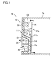
FIG. 1] FIG. 1 is a longitudinal cross-sectional view of a container refrigeration apparatus according to an embodiment and a container body. - [
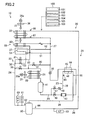
FIG. 2] FIG. 2 is a refrigerant circuit diagram of the container refrigeration apparatus according to the embodiment. - [
FIG. 3] FIG. 3 is a flow chart illustrating a different refrigerant charging detection operation. - [
FIG. 4] FIG. 4 is a flow chart illustrating a different refrigerant charging detection operation in a situation where the container refrigeration apparatus is sensed to be out of gas. - Embodiments of the present invention will be described hereinafter in detail with reference to the drawings. Note that the following embodiments are merely preferred examples in nature, and are not intended to limit the scope, applications, and use of the invention.
- As illustrated in
FIG. 1 , a container refrigeration apparatus (10) of this embodiment is configured to cool the interior of a container for use in, for example, marine transportation, and forms a refrigeration apparatus according to the present invention. The container refrigeration apparatus (10) includes a refrigerant circuit including a compressor (30), a condenser (31), and an evaporator (33), and forms a refrigeration cycle. Furthermore, the container refrigeration apparatus (10) serves as a lid body blocking an open lateral end of a container body (1a). - A casing (13) of the container refrigeration apparatus (10) includes a casing body (11) separating the outside of the container from the interior of the container, a partition plate (14) provided toward the back surface of the casing body (11) (toward the interior of the container), and other components.
- The casing body (11) has a double structure of an inside casing (11a) made of aluminum and an outside casing (11b) made of fiber reinforced plastics (FRP). A thermal barrier (11c) made of a foam material is formed between the inside casing (11a) and the outside casing (11b).
- Furthermore, a lower portion of the casing body (11) is formed with a bulge (12) protruding toward the interior of the container. While the interior of the bulge (12) forms an outside accommodation space (S1), an upper portion of the casing (13) toward the back surface of the casing body (11) forms an inside accommodation space (S2) above the bulge (12).
- While the compressor (30), the condenser (31), an outside fan (35), and an electrical component box (not shown) are accommodated in the outside accommodation space (S1), the evaporator (33) and an inside fan (36) are placed in the inside accommodation space (S2). An air passage (S3) through which inside air flows is formed between the bulge (12) and the partition plate (14). While the upper end of the air passage (S3) communicates with the inside accommodation space (S2), the lower end thereof communicates with the interior of the container.
- As illustrated in
FIG. 2 , the container refrigeration apparatus (10) includes a refrigerant circuit (20) through which refrigerant flows to perform a refrigeration cycle. The refrigerant circuit (20) includes a main circuit (21), a hot gas bypass circuit (22), a reheat circuit (80), and a subcooling circuit (23). - The main circuit (21) includes the compressor (30), the condenser (31), a main expansion valve (32), and the evaporator (33) that are sequentially connected in series through refrigerant pipes.
- The compressor (30) includes a motor (not shown) for driving a compression mechanism. The rotational speed of the motor of the compressor (30) is controlled in multiple stages by an inverter. Specifically, the compressor (30) is a variable capacity compressor the operating rotational speed of which is variable. A circuit board of the inverter connected to the compressor (30) is accommodated in the electrical component box.
- The condenser (31) and the evaporator (33) are both fin-and-tube heat exchangers. The condenser (31) is placed outside the container as described above. Outside air and the refrigerant exchange heat in the condenser (31). The evaporator (33) is placed inside the container as described above. Inside air and the refrigerant exchange heat in the evaporator (33). Although not shown in
FIG. 1 , a drain pan (37) is provided below the evaporator (33). The drain pan (37) is a flat container having an opening facing upward. The drain pan (37) collects, for example, frost and ice blocks falling from the evaporator (33), and water condensed from the air. - The degree of opening of the main expansion valve (32) can be adjusted in multiple stages by a pulse motor. While the outside fan (35) is provided near the condenser (31), the inside fan (36) is provided near the evaporator (33). The inside fan (36) is configured to supply air cooled by the evaporator (33) into the container. The outside fan (35) and the inside fan (36) include an outside fan motor (35a) and an inside fan motor (36a), respectively.
- A high pressure gas pipe (24) between the compressor (30) and the condenser (31) includes a fourth open/close valve (38). The degree of opening of the fourth open/close valve (38) can be adjusted in multiple stages by a pulse motor.
- A receiver (41), a second open/close valve (49), a dryer (43), and a subcooling heat exchanger (44) are sequentially provided in a high pressure liquid pipe (25) between the condenser (31) and the main expansion valve (32). The receiver (41) is provided downstream of the condenser (31) to receive the refrigerant flowing through the condenser (31) and separate the received refrigerant into saturated liquid and saturated gas. The second open/close valve (49) is a solenoid valve which is freely opened and closed. The dryer (43) is configured to capture moisture in a liquid refrigerant flowing through the condenser (31). A liquid seal preventing pipe (90) connected downstream of the main expansion valve (32) is connected upstream of the condenser (31). The liquid seal preventing pipe (90) includes a liquid seal open/close valve (91).
- The subcooling heat exchanger (44) cools the liquid refrigerant flowing through the condenser (31). The subcooling heat exchanger (44) includes a primary passage (45) and a secondary passage (46). Specifically, in the subcooling heat exchanger (44), the refrigerant flowing through the primary passage (45) and the refrigerant flowing through the secondary passage (46) exchange heat. The primary passage (45) is connected to the high pressure liquid pipe (25) of the main circuit (21), and the secondary passage (46) is connected to a subcooling branch pipe (26) of the subcooling circuit (23). An inlet end of the subcooling branch pipe (26) is connected to the high pressure liquid pipe (25) between the receiver (41) and the second open/close valve (49). An outlet end of the subcooling branch pipe (26) is connected to a compression chamber in the compressor (30) at an intermediate pressure (intermediate pressure compression chamber). Specifically, the subcooling branch pipe (26) is a passage into which part of the liquid refrigerant in the high pressure liquid pipe (25) is diverted and flows into the intermediate pressure compression chamber of the compressor (30). A first open/close valve (47) and a subcooling expansion valve (48) are provided on the subcooling branch pipe (26) near an inlet of the secondary passage (46). The first open/close valve (47) is a solenoid valve which is freely opened and closed. The degree of opening of the subcooling expansion valve (48) can be adjusted in multiple stages by a pulse motor. The subcooling expansion valve (48) forms a decompression mechanism for decompressing the refrigerant.
- The hot gas bypass circuit (22) includes a single main passage (50), and two branch passages (51, 52) branched from the main passage (50). The two branch passages (51, 52) include a first branch passage (51) and a second branch passage (52). An inlet end of the main passage (50) is connected to the high pressure gas pipe (24) between the fourth open/close valve (38) and the discharge side of the compressor (30). A third open/close valve (53) is provided in the main passage (50). The third open/close valve (53) is a solenoid valve which is freely opened and closed.
- One end of the first branch passage (51) is connected to an outlet end of the main passage (50), and the other end is connected to a low pressure liquid pipe (27) between the main expansion valve (32) and the evaporator (33). Likewise, one end of the second branch passage (52) is connected to the outlet end of the main passage (50), and the other end is connected to the low pressure liquid pipe (27). The second branch passage (52) is made of a refrigerant pipe longer than the first branch passage (51). The second branch passage (52) includes a drain pan heater (54) that extends in a serpentine form on a bottom of the drain pan (37). The drain pan heater (54) is configured to heat the inside of the drain pan (37) with the refrigerant. Thus, the hot gas bypass circuit (22) forms a bypass circuit for feeding the refrigerant compressed in the compressor (30) (a high temperature gaseous refrigerant discharged from the compressor (30)) to the evaporator (33).
- The reheat circuit (80) includes a reheat passage (82). An inlet end of the reheat passage (82) is connected to the high pressure gas pipe (24) between the fourth open/close valve (38) and the discharge side of the compressor (30). A fifth open/close valve (81) is provided in the reheat passage (82). The fifth open/close valve (81) is a solenoid valve which is freely opened and closed. The reheat passage (82) includes a reheat heat exchanger (83) and a capillary tube. The reheat heat exchanger (83) exchanges heat between the discharged refrigerant flown thereinto and air cooled and dehumidified by the evaporator (33) in a dehumidification mode to heat the air. The reheat heat exchanger (83) is a fin-and-tube heat exchanger. The capillary tube decompresses the refrigerant flowing out of the reheat heat exchanger (83). Thus, the reheat circuit (80) forms a circuit for feeding part of the refrigerant compressed in the compressor (30) (a high temperature gaseous refrigerant discharged from the compressor (30)) to the reheat heat exchanger (83).
- The refrigerant circuit (20) includes various sensors. Specifically, a high pressure sensor (60), a high pressure switch (61), and a discharge temperature sensor (62) are provided on the high pressure gas pipe (24). The high pressure sensor (60) detects the pressure of the high pressure gaseous refrigerant discharged from the compressor (30). The discharge temperature sensor (62) detects the temperature of the high pressure gaseous refrigerant discharged from the compressor (30). A low pressure sensor (63) and a suction temperature sensor (64) are provided on a low pressure gas pipe (28) between the evaporator (33) and the compressor (30). The low pressure sensor (63) detects the pressure of the low pressure gaseous refrigerant sucked into the compressor (30). The suction temperature sensor (64) detects the temperature of the low pressure gaseous refrigerant sucked into the compressor (30).
- An inlet temperature sensor (65) and an outlet temperature sensor (66) are provided on the subcooling branch pipe (26) near the inlet and the outlet of the secondary passage (46), respectively. The inlet temperature sensor (65) detects the temperature of the refrigerant immediately before the refrigerant flows into the secondary passage (46). The outlet temperature sensor (66) detects the temperature of the refrigerant immediately after the refrigerant has flowed out of the secondary passage (46).
- An inlet temperature sensor (67) is provided on the low pressure liquid pipe (27) near an inlet of the evaporator (33). The inlet temperature sensor (67) detects the temperature of the refrigerant immediately before the refrigerant flows into the evaporator (33). An outlet temperature sensor (68) is provided on the low pressure gas pipe (28) near an outlet of the evaporator (33). The outlet temperature sensor (68) detects the temperature of the refrigerant immediately after the refrigerant has flowed out of the evaporator (33).
- An outside temperature sensor (69) is provided outside the container near an inlet of the condenser (31). The outside temperature sensor (69) detects the temperature of outside air (i.e., outside temperature) immediately before the air is sucked into the condenser (31). An inlet temperature sensor (70) is provided inside the container near an inlet of the evaporator (33), and an outlet temperature sensor (71) is provided inside the container near an outlet of the evaporator (33). The inlet temperature sensor (70) detects the temperature of inside air immediately before the air passes through the evaporator (33). The outlet temperature sensor (71) detects the temperature of the inside air (the inlet air temperature SS) immediately after the air has passed through the evaporator (33).
- The container refrigeration apparatus (10) includes a controller (100) as a control unit for controlling the refrigerant circuit (20). The controller (100) includes a characteristics determiner (101), an alarm (102), a data storage (103), an actuation authorization section (104), an actuation prohibition section (105), and an operation switch (106) to perform a different refrigerant charging detection operation described below. The different refrigerant charging detection operation will be described below in detail. The operation switch (106) forms an operation start control section according to the present invention.
- Next, the operational behavior of the container refrigeration apparatus (10) will be described. The operational behavior of the container refrigeration apparatus (10) is broadly grouped under a "cooling mode," a "defrosting mode," and a "dehumidification mode." The cooling mode is selected to cool the temperature inside the container at a relatively low temperature. Specifically, the cooling mode is selected to perform cold storage/freezing of items contained in the container body (1a) (e.g., perishable food). The defrosting mode is selected to melt frost adhered to a surface of, for example, a heat transfer pipe of the evaporator (33) by introducing a refrigerant discharged from the compressor (30) into the hot gas bypass circuit (22). The defrosting mode is performed every time a predetermined period elapses, for example, from the start of the cooling mode, and after the termination of the defrosting mode, the cooling mode is restarted.
- In this embodiment, an operation in each of the defrosting mode and the dehumidification mode will not be described, and the principal operation in the cooling mode will be described.
- In the principal cooling operation in the cooling mode, the first open/close valve (47) and the second open/close valve (49) are opened, and the third open/close valve (53) and the fifth open/close valve (81) are closed. The fourth open/close valve (38) is fully opened, and the degrees of opening of the subcooling expansion valve (48) and the main expansion valve (32) are suitably adjusted. The compressor (30), the outside fan (35), and the inside fan (36) are operated.
- The refrigerant compressed in the compressor (30) is condensed in the condenser (31), and then passes through the receiver (41). Part of the refrigerant that has passed through the receiver (41) flows through the low pressure liquid pipe (27), and the rest of the refrigerant flows into the subcooling branch pipe (26). The refrigerant passing through the low pressure liquid pipe (27) is decompressed by the main expansion valve (32), and then flows through the evaporator (33). In the evaporator (33), the refrigerant absorbs heat of the inside air to evaporate. Thus, the inside air is cooled. The refrigerant evaporated in the evaporator (33) is sucked into the compressor (30), and is compressed again.
- The refrigerant that has flowed into the subcooling branch pipe (26) is decompressed to an intermediate pressure by passing through the subcooling expansion valve (48), and then flows through the secondary passage (46) of the subcooling heat exchanger (44). In the subcooling heat exchanger (44), the refrigerant flowing through the primary passage (45) and the refrigerant flowing through the secondary passage (46) exchange heat. As a result, the refrigerant flowing through the primary passage (45) is subcooled, while the refrigerant flowing through the secondary passage (46) evaporates. The refrigerant flowing out of the secondary passage (46) is sucked into the intermediate pressure compression chamber through an intermediate port of the compressor (30).
- Next, a method for detecting whether a different refrigerant has been charged into the container refrigeration apparatus (10) will be described with reference to
FIGS. 3 and4 . The method for detecting whether a different refrigerant has been charged is a method for detecting whether a refrigerant different from a normal refrigerant (a refrigerant selected as a refrigerant to be charged) has been charged into the refrigerant circuit (20). In this embodiment, the normal refrigerant is refrigerant R134a. The type of the refrigerant herein is an example. - When a refrigerant is fully charged into the refrigerant circuit (20), such a different refrigerant charging detection operation as illustrated in the flow chart of
FIG. 3 is performed. - First, an operator evacuates the refrigerant circuit (20) before charging the refrigerant thereinto to remove air in the refrigerant circuit (20). This evacuation allows the internal pressure of each of the refrigerant pipes of the refrigerant circuit (20) to be zero or less, and the pressure is recorded in the characteristics determiner (101). Specifically, a value detected by the low pressure sensor (63) (zero or less) is recorded in the characteristics determiner (101) (step ST1).
- Next, the operator fully charges a refrigerant into the refrigerant circuit (20) (step ST2, a charging step). The refrigerant is charged into the refrigerant circuit (20) to increase the internal pressures of the refrigerant pipes. If the value detected by the low pressure sensor (63), i.e., zero or less, has been recorded in the characteristics determiner (101), the characteristics determiner (101) performs a characteristics determination step (step ST3). In the characteristics determination step, the saturation temperature characteristics of the charged refrigerant are first derived from the pressure and temperature thereof. A determination is made whether the derived saturation temperature characteristics are identical to the saturation temperature characteristics of the previously determined normal refrigerant. Specifically, the value detected by the low pressure sensor (63) is input, as the pressure of the charged refrigerant, to the characteristics determiner (101). Furthermore, the value detected by the outside temperature sensor (69) is input, as the temperature of the charged refrigerant, to the characteristics determiner (101). The characteristics determiner (101) derives the saturation temperature characteristics of the charged refrigerant from the input pressure and temperature.
- When a refrigerant is charged into the refrigerant circuit (20), it is slightly vaporized, and its temperature changes. For this reason, even if the temperature of the charged refrigerant is detected by, for example, the suction temperature sensor (64) or the discharge temperature sensor (62), a very accurate temperature cannot be detected. Thus, the value detected by the outside temperature sensor (69) is used as the temperature of the refrigerant before being charged, i.e., the temperature of the refrigerant outside the container, to obtain the accurate temperature of the refrigerant. This enables the derivation of the accurate saturation temperature characteristics of the charged refrigerant. A value detected by not the low pressure sensor (63) but the high pressure sensor (60) may be input, as the pressure of the charged refrigerant, to the characteristics determiner (101).
- When the characteristics determiner (101) determines that the derived saturation temperature characteristics are different from those of the normal refrigerant, the alarm (102) issues an alarm indicating that the charged refrigerant is different from the normal refrigerant (step ST4, an alerting step). When the alarm is issued, the operator collects the refrigerant in the refrigerant circuit (20), and again evacuates the refrigerant circuit (20). This process again proceeds to step ST1. The above operations enable the detection of a situation where a refrigerant different from the normal refrigerant has been charged.
- In contrast, when the characteristics determiner (101) determines that the derived saturation temperature characteristics are identical to those of the normal refrigerant, the operator manually inputs refrigerant charging information to the data storage (103) (step ST5, an inputting step). The refrigerant charging information includes the "type of the charged refrigerant," "the amount of the refrigerant charged," "whether the refrigerant circuit is filled," a "cylinder number" for the charged refrigerant, the "name of a company to which the operator having charged the refrigerant belongs (repair shop code)," and the "name" of the operator. The refrigerant charging information is not limited to the above examples except for the "type of the refrigerant," and may include only the "type of the refrigerant." In a situation where the "cylinder number" for the charged refrigerant, the "name of a company to which the operator having charged the refrigerant belongs (repair shop code)," and the "name" of the operator are input as the refrigerant charging information, if a refrigerant different from the normal refrigerant is charged into the refrigerant circuit to operate the refrigeration apparatus, and a decrease in refrigeration capacity or damage to a refrigeration machine is caused, where the responsibility for such a problem lies can be clarified.
- Subsequently, the actuation authorization section (104) determines whether the "type of the refrigerant" input to the data storage (103) is identical to the type of the normal refrigerant (step ST6, a type determining step). When the actuation authorization section (104) determines that the input type is identical to the type of the normal refrigerant, it outputs an "operation start authorization" signal to the data storage (103), and the signal is recorded in the data storage (103) (step ST7, an operation authorization step). This allows the start of operation of the container refrigeration apparatus (10), i.e., the actuation of the compressor (30).
- In contrast, when the actuation authorization section (104) determines that the input type is different from the type of the normal refrigerant, it outputs a corresponding signal to the actuation prohibition section (105). Then, the actuation prohibition section (105) determines whether the "type of the refrigerant" input to the data storage (103) is identical to the type of a predetermined refrigerant different from the normal refrigerant (step ST8, a type determining step). In this embodiment, the predetermined refrigerant is refrigerant R40. The refrigerant R40 has saturation temperature characteristics substantially equivalent to those of the normal refrigerant R134a, and is not so compatible with the container refrigeration apparatus (10) of this embodiment.
- When the actuation prohibition section (105) determines that the type of the refrigerant input to the data storage (103) does not correspond to the type of the predetermined refrigerant (R40), the alarm (102) issues an alarm indicating that the charged refrigerant is different from the normal refrigerant (step ST4). When the actuation prohibition section (105) determines that the type of the refrigerant input to the data storage (103) is identical to the type of the predetermined refrigerant (R40), it outputs an "operation start disapproval" signal to the data storage (103), and the signal is recorded in the data storage (103) (step ST, a forcible prohibition step). This disables the start of operation of the container refrigeration apparatus (10), i.e., the actuation of the compressor (30). In other words, one of the "operation start authorization" signal or the "operation start disapproval" signal is recorded in the data storage (103), and when the "operation start disapproval" signal has been recorded, the compressor (30) cannot be actuated.
- When the operator turns the operation switch (106) on (step ST10), the actuation authorization section (104) determines whether or not the "operation start authorization" signal has been recorded in the data storage (103) (step ST11). If the "operation start authorization" signal has been recorded, the compressor (30) is actuated to start operation of the container refrigeration apparatus (10). If no "operation start authorization" signal has been recorded, i.e., if the "operation start disapproval" signal has been recorded, the compressor (30) is not actuated, and the operator performs operations to cancel the recorded "operation start disapproval" signal. For example, the operator collects the refrigerant in the refrigerant circuit (20), evacuates the refrigerant circuit (20), and again charges the normal refrigerant into the refrigerant circuit (20). In other words, the operator performs operations such that this process returns to step ST1. Thus, when, in step ST7, the "operation start authorization" signal is recorded, the recorded "operation start disapproval" signal is canceled.
- Next, when a refrigerant is additionally charged into the refrigerant circuit (20), such a different refrigerant charging detection operation as illustrated in the flow chart of
FIG. 4 is performed. Here, a case where during operation, the refrigerant circuit (20) is sensed to be out of gas, and thus a refrigerant is additionally charged into the refrigerant circuit (20) will be described. - When the refrigerant circuit (20) is sensed to be out of gas, for example, during the above-described cooling mode (step ST20), the operator additionally charges a refrigerant into the refrigerant circuit (20) while continuing the cooling mode, i.e., with the compressor (30) driven (step ST21). The situation where the refrigerant circuit (20) is out of gas corresponds to a situation where the amount of the refrigerant in the refrigerant circuit (20) is inadequate.
- In this embodiment, for example, when the value detected by the low pressure sensor (63) abnormally decreases within a predetermined period (e.g., two seconds) from the actuation of the compressor (30), when the value detected by the discharge temperature sensor (62) abnormally increases within the predetermined period therefrom, or when the degree of opening of the main expansion valve (32) is higher than or equal to a predetermined value within the predetermined period therefrom, the controller (100) issues an alarm indicating that the refrigerant circuit (20) is "out of gas." The operator additionally charges the refrigerant into the refrigerant circuit (20) due to the alarm. The operator can recognize the refrigerant circuit (20) as being out of gas. For example, when flash gas (bubbles) flows through a liquid indicator, the operator determines that the refrigerant circuit (20) is out of gas.
- When the operator additionally charges the refrigerant into the refrigerant circuit (20), the operator manually inputs refrigerant charging information in a manner similar to that in the above-described case where a refrigerant is fully charged into the refrigerant circuit (20) (step ST5 in
FIG. 3 , an inputting step). In steps subsequent to step ST5 except steps ST7, ST10, ST11, and ST12 inFIG. 3 , operations similar to those in the above-described case where a refrigerant is fully charged into the refrigerant circuit (20) are performed. - When operation is normally started, operations in the steps ST10, ST11, and ST12 illustrated in
FIG. 3 are performed. Specifically, when the operator turns the operation switch (106) on, the actuation authorization section (104) determines whether or not the "operation start authorization" signal has been recorded in the data storage (103) (step ST11). When the "operation start authorization" signal has been recorded, the compressor (30) is actuated to start the cooling mode. Alternatively, when the "operation start authorization" signal has not been recorded, i.e., when the "operation start disapproval" signal has been recorded, the compressor (30) is not actuated, and in this case, the operator performs operations to cancel the recorded "operation start disapproval" signal. - Even when an operator different from a refrigerant charger turns the operation switch (106) on at, for example, a port different from a port at which the refrigerant was charged, the recorded "operation start authorization" signal can ensure the start of operation of the container refrigeration apparatus (10) (actuation of the compressor (30)). Alternatively, when the "operation start disapproval" signal has been recorded, the recorded "operation start disapproval" signal can ensure the prevention of the start of operation of the container refrigeration apparatus (10) (actuation of the compressor (30)).
- As described above, according to the embodiment, when the saturation temperature characteristics of a refrigerant charged into the refrigerant circuit (20) are derived, and the derived saturation temperature characteristics are different from those of a normal refrigerant, an alarm is issued. This can ensure the detection of a situation where a refrigerant different from the normal refrigerant has been charged into the refrigerant circuit (20). This can prevent problems, such as a decrease in refrigeration capacity or an abnormal increase in high pressure due to the charging of the refrigerant different from the normal refrigerant, before they occur. Thus, a highly reliable container refrigeration apparatus (10) can be provided.
- Furthermore, according to the embodiment, when the saturation temperature characteristics of the refrigerant charged into the refrigerant circuit (20) are identical to those of the normal refrigerant, the type of the charged refrigerant is input, and when the input type is identical to the type of the predetermined refrigerant different from the normal refrigerant, the start of operation of the container refrigeration apparatus (10) (i.e., actuation of the compressor (30)) is forcibly prohibited. Thus, even when the charged refrigerant has saturation temperature characteristics equivalent to those of the normal refrigerant, a situation where a refrigerant incompatible with a refrigeration machine, such as the compressor (30), of the container refrigeration apparatus (10) has been charged can be detected with reliability. Furthermore, even if the operator attempts to forcibly start operation of the container refrigeration apparatus (10), the operation of the container refrigeration apparatus (10) can be reliably prevented from starting. This can prevent, for example, damage to the refrigeration machine before it occurs. Thus, a more highly reliable container refrigeration apparatus (10) can be provided.
- In the embodiment, also when the refrigerant circuit (20) is sensed to be out of gas, and accordingly, a refrigerant is additionally charged, the type of the charged refrigerant is input, and when the input type of the refrigerant is different from the type of the normal refrigerant, an alarm is issued, or the "operation start disapproval" signal is recorded. This can prevent the above-described problems before they occur.
- In the embodiment, not only the type of the charged refrigerant, but also a cylinder number for the charged refrigerant, the name of a company to which the operator having charged the refrigerant belongs, and the name of the operator are manually input so as to be recorded as refrigerant charging information. For this reason, even if a refrigerant different from the normal refrigerant has been charged, where the responsibility for such a problem lies can be clarified by, for example, the input name of the operator.
- The different refrigerant charging detection operation of the embodiment may be configured as follows.
- For example, when in step ST3 illustrated in
FIG. 3 , a determination is made that the saturation temperature characteristics of the charged refrigerant are identical to those of the normal refrigerant, the operator himself or herself performs operations to check whether or not the type of the charged refrigerant is identical to the type of the previously determined normal refrigerant. When the operator recognizes the type of the charged refrigerant as being identical to the type of the normal refrigerant, operation of the container refrigeration apparatus (10) is started. Specifically, the operator turns the operation switch (106) on to actuate the compressor (30). When the operator recognizes the type of the charged refrigerant as being different from the type of the normal refrigerant, the container refrigeration apparatus (10) is not operated. - While, in the embodiment, the container refrigeration apparatus (10) was described, the present invention is not limited to the container refrigeration apparatus (10), and can be applied to other refrigeration apparatuses, such as an air conditioner.
- As described above, the present invention is useful for a refrigeration apparatus including a refrigerant circuit through which a refrigerant circulates to perform a refrigeration cycle, and a method for detecting whether a different refrigerant has been charged into the refrigerant circuit.
-
- 10
- Container Refrigeration Apparatus
- 20
- Refrigerant Circuit
- 30
- Compressor
- 101
- Characteristics Determiner
- 102
- Alarm
- 103
- Data Storage
- 104
- Actuation Authorization Section
- 105
- Actuation Prohibition Section
Claims (12)
- A method for detecting whether a different refrigerant has been charged into a refrigeration apparatus including a refrigerant circuit (20) through which a refrigerant circulates and which thus performs a refrigeration cycle, the method comprising:a charging step of charging a refrigerant into the refrigerant circuit (20);a characteristics determination step of determining whether saturation temperature characteristics of the refrigerant charged in the charging step are identical to saturation temperature characteristics of a previously determined normal refrigerant, the saturation temperature characteristics of the refrigerant being derived from a pressure and a temperature of the refrigerant; andan alerting step of, when, in the characteristics determination step, a determination is made that the saturation temperature characteristics of the refrigerant charged in the charging step are different from the saturation temperature characteristics of the previously determined normal refrigerant, issuing an alarm indicating that the charged refrigerant is different from the normal refrigerant.
- The method of claim 1 further comprising:an inputting step of, when, in the characteristics determination step, a determination is made that the saturation temperature characteristics of the refrigerant charged in the charging step are identical to the saturation temperature characteristics of the previously determined normal refrigerant, manually inputting a type of the charged refrigerant to a data storage (103); anda forcible prohibition step of, when the type input to the data storage (103) is identical to a type of a predetermined refrigerant different from the previously determined normal refrigerant, forcibly prohibiting start of operation of the refrigeration apparatus.
- The method of claim 2 further comprising:an operation authorization step of, when the type input to the data storage is identical to a type of the previously determined normal refrigerant, recording a signal allowing start of operation of the refrigeration apparatus in the data storage (103).
- The method of claim 1, wherein
when, in the characteristics determination step, a determination is made that the saturation temperature characteristics of the refrigerant charged in the charging step are identical to the saturation temperature characteristics of the previously determined normal refrigerant, an operator checks whether or not a type of the charged refrigerant is identical to a type of the previously determined normal refrigerant, and the operator starts operation of the refrigeration apparatus when the type of the charged refrigerant is identical to the type of the previously determined normal refrigerant. - The method of claim 2, wherein
in the inputting step, not only the type of the charged refrigerant, but also a cylinder number for the charged refrigerant, a name of a company to which an operator having charged the refrigerant belongs, and a name of the operator are manually input to the data storage. - The method of claim 1, wherein
the refrigerant circuit (20) adjusts a temperature of inside air. - A refrigeration apparatus including a refrigerant circuit (20) which is connected to a compressor (30), through which a refrigerant circulates, and which thus performs a refrigeration cycle, the apparatus comprising:a characteristics determiner (101) configured to derive saturation temperature characteristics of a refrigerant charged into the refrigerant circuit (20) from a pressure and a temperature of the refrigerant after an internal pressure of a refrigerant pipe of the refrigerant circuit (20) has reached zero or less, and determine whether the saturation temperature characteristics are identical to saturation temperature characteristics of a previously determined normal refrigerant; andan alarm (102) configured to, when the characteristics determiner (101) determines that the saturation temperature characteristics are different from the saturation temperature characteristics of the normal refrigerant, issue an alarm indicating that the refrigerant charged into the refrigerant circuit (20) is different from the normal refrigerant.
- The apparatus of claim 7 further comprising:a data storage (103) to which, when the characteristics determiner (101) determines that the saturation temperature characteristics of the charged refrigerant are identical to the saturation temperature characteristics of the normal refrigerant, a type of the refrigerant charged into the refrigerant circuit (20) is manually input; andan actuation prohibition section (105) configured to, when the type input to the data storage (103) is identical to a type of a predetermined refrigerant different from the previously determined normal refrigerant, forcibly prohibit actuation of the compressor (30).
- The apparatus of claim 8 further comprising:an actuation authorization section (104) configured to, when the type input to the data storage (103) is identical to a type of the previously determined normal refrigerant, record a signal allowing actuation of the compressor (30) in the data storage (103).
- The apparatus of claim 7, wherein
when the characteristics determiner (101) determines that the saturation temperature characteristics of the charged refrigerant are identical to the saturation temperature characteristics of the normal refrigerant, an operator checks whether or not a type of the charged refrigerant is identical to a type of the previously determined normal refrigerant, and
the refrigeration apparatus further includes an operation start control section configured to, when the type of the charged refrigerant is identical to the type of the previously determined normal refrigerant, actuate the compressor (30). - The apparatus of claim 8, wherein
not only the type of the charged refrigerant, but also a cylinder number for the charged refrigerant, a name of a company to which an operator having charged the refrigerant belongs, and a name of the operator are manually input to the data storage (103). - The apparatus of claim 7, wherein
the refrigerant circuit (20) adjusts a temperature of inside air.
Applications Claiming Priority (2)
| Application Number | Priority Date | Filing Date | Title |
|---|---|---|---|
| JP2011290214A JP5445577B2 (en) | 2011-12-29 | 2011-12-29 | Refrigeration apparatus and method of detecting different refrigerant filling |
| PCT/JP2012/008227 WO2013099200A1 (en) | 2011-12-29 | 2012-12-25 | Refrigeration device and method for detecting filling of wrong refrigerant |
Publications (3)
| Publication Number | Publication Date |
|---|---|
| EP2801772A1 true EP2801772A1 (en) | 2014-11-12 |
| EP2801772A4 EP2801772A4 (en) | 2015-10-07 |
| EP2801772B1 EP2801772B1 (en) | 2021-03-17 |
Family
ID=48696742
Family Applications (1)
| Application Number | Title | Priority Date | Filing Date |
|---|---|---|---|
| EP12862282.6A Active EP2801772B1 (en) | 2011-12-29 | 2012-12-25 | Refrigeration device and method for detecting filling of wrong refrigerant |
Country Status (7)
| Country | Link |
|---|---|
| US (1) | US20140373559A1 (en) |
| EP (1) | EP2801772B1 (en) |
| JP (1) | JP5445577B2 (en) |
| CN (1) | CN103998876B (en) |
| DK (1) | DK2801772T3 (en) |
| SG (1) | SG11201403680QA (en) |
| WO (1) | WO2013099200A1 (en) |
Families Citing this family (3)
| Publication number | Priority date | Publication date | Assignee | Title |
|---|---|---|---|---|
| CN103530989A (en) * | 2013-10-29 | 2014-01-22 | 江苏物联网研究发展中心 | Alarm device for preventing food from deteriorating |
| JP2019011899A (en) * | 2017-06-30 | 2019-01-24 | 株式会社富士通ゼネラル | Air conditioning device |
| CN110887168B (en) * | 2018-09-10 | 2021-05-18 | 奥克斯空调股份有限公司 | Air conditioner refrigerant shortage detection method and air conditioner |
Family Cites Families (15)
| Publication number | Priority date | Publication date | Assignee | Title |
|---|---|---|---|---|
| US4939905A (en) * | 1989-12-04 | 1990-07-10 | Kent-Moore Corporation | Recovery system for differing refrigerants |
| US5285647B1 (en) * | 1993-03-08 | 1999-02-23 | Spx Corp | Refrigerant handling system with air purge and multiple refrigerant capabilities |
| JPH0849947A (en) * | 1994-08-04 | 1996-02-20 | Zexel Corp | Recovering-filling equipment of refrigerant |
| JPH09329375A (en) * | 1996-06-10 | 1997-12-22 | Sanyo Electric Co Ltd | Replenishing/filling method of non-azeorope refrigerant and device thereof |
| JPH102642A (en) * | 1996-06-17 | 1998-01-06 | Hitachi Ltd | Refrigerating cycle |
| JPH11159895A (en) * | 1997-11-28 | 1999-06-15 | Hitachi Ltd | Air conditioner |
| DE10061545A1 (en) * | 2000-12-11 | 2002-06-13 | Behr Gmbh & Co | Procedure for refrigerant level monitoring |
| JP2002267232A (en) * | 2001-03-12 | 2002-09-18 | Hitachi Ltd | Service system and service-providing device for air conditioner |
| US6892546B2 (en) * | 2001-05-03 | 2005-05-17 | Emerson Retail Services, Inc. | System for remote refrigeration monitoring and diagnostics |
| JP3714304B2 (en) | 2002-07-10 | 2005-11-09 | ダイキン工業株式会社 | Refrigeration equipment |
| JP4284534B2 (en) * | 2004-09-01 | 2009-06-24 | 三菱電機株式会社 | Refrigerated refrigerator with RFID (IC tag) |
| JP4165566B2 (en) * | 2006-01-25 | 2008-10-15 | ダイキン工業株式会社 | Air conditioner |
| JP4225357B2 (en) * | 2007-04-13 | 2009-02-18 | ダイキン工業株式会社 | Refrigerant filling apparatus, refrigeration apparatus and refrigerant filling method |
| US8301403B2 (en) * | 2009-09-14 | 2012-10-30 | Weick Brian K | Hand held refrigeration gauge |
| ITTV20110073A1 (en) * | 2011-05-30 | 2012-12-01 | Texa Spa | GAS ANALYZER SYSTEM CONFIGURED TO DETERMINE THE CONCENTRATION OF A REFRIGERANT GAS AND / OR OF CONTAMINATING GAS PRESENT IN A SELF-MULTI-AIR AIR CONDITIONING SYSTEM |
-
2011
- 2011-12-29 JP JP2011290214A patent/JP5445577B2/en active Active
-
2012
- 2012-12-25 WO PCT/JP2012/008227 patent/WO2013099200A1/en active Application Filing
- 2012-12-25 DK DK12862282.6T patent/DK2801772T3/en active
- 2012-12-25 EP EP12862282.6A patent/EP2801772B1/en active Active
- 2012-12-25 CN CN201280062343.XA patent/CN103998876B/en active Active
- 2012-12-25 US US14/369,521 patent/US20140373559A1/en not_active Abandoned
- 2012-12-25 SG SG11201403680QA patent/SG11201403680QA/en unknown
Also Published As
| Publication number | Publication date |
|---|---|
| JP2013139948A (en) | 2013-07-18 |
| JP5445577B2 (en) | 2014-03-19 |
| SG11201403680QA (en) | 2014-10-30 |
| US20140373559A1 (en) | 2014-12-25 |
| CN103998876A (en) | 2014-08-20 |
| WO2013099200A1 (en) | 2013-07-04 |
| CN103998876B (en) | 2016-07-06 |
| EP2801772A4 (en) | 2015-10-07 |
| DK2801772T3 (en) | 2021-05-17 |
| EP2801772B1 (en) | 2021-03-17 |
Similar Documents
| Publication | Publication Date | Title |
|---|---|---|
| US11635239B2 (en) | Refrigeration system with purge and acid filter | |
| JP5659292B2 (en) | Dual refrigeration cycle equipment | |
| EP2505939B1 (en) | Refrigeration device for container | |
| EP2600083B1 (en) | Refrigeration device | |
| US20110174005A1 (en) | Refrigerating apparatus | |
| US20120055185A1 (en) | Refrigeration apparatus | |
| WO2007029803A1 (en) | Refrigeration device | |
| EP2881684B1 (en) | Container refrigeration device | |
| US11162724B2 (en) | Method for controlling ejector capacity in a vapour compression system | |
| CN105135772B (en) | Water refrigerating plant and its control method for preventing cold water from freezing | |
| US11421925B2 (en) | Container refrigeration apparatus with impact event assessment and abnormality diagnosis | |
| JPH09318169A (en) | Refrigerating apparatus | |
| US20220186987A1 (en) | Heat source-side unit and refrigeration apparatus | |
| EP2801772B1 (en) | Refrigeration device and method for detecting filling of wrong refrigerant | |
| EP2881685B1 (en) | Container refrigeration device and control method thereof | |
| JP2009109110A (en) | Refrigeration system | |
| JP6621017B2 (en) | Refrigeration equipment | |
| JP4869320B2 (en) | Refrigeration cycle apparatus and water heater equipped with the same | |
| JP5200120B2 (en) | Valve check method for refrigeration circuit | |
| WO2021033426A1 (en) | Heat source unit and freezing apparatus | |
| JP2008267691A (en) | Air conditioner | |
| EP3851764A1 (en) | Cooling system with flooded low side heat exchangers | |
| JP5260684B2 (en) | Refrigeration circuit | |
| KR20070120848A (en) | Oil seperating apparatus for compressor | |
| JP4284823B2 (en) | Refrigeration equipment |
Legal Events
| Date | Code | Title | Description |
|---|---|---|---|
| PUAI | Public reference made under article 153(3) epc to a published international application that has entered the european phase |
Free format text: ORIGINAL CODE: 0009012 |
|
| 17P | Request for examination filed |
Effective date: 20140708 |
|
| AK | Designated contracting states |
Kind code of ref document: A1 Designated state(s): AL AT BE BG CH CY CZ DE DK EE ES FI FR GB GR HR HU IE IS IT LI LT LU LV MC MK MT NL NO PL PT RO RS SE SI SK SM TR |
|
| DAX | Request for extension of the european patent (deleted) | ||
| RA4 | Supplementary search report drawn up and despatched (corrected) |
Effective date: 20150908 |
|
| RIC1 | Information provided on ipc code assigned before grant |
Ipc: F25B 49/02 20060101ALI20150902BHEP Ipc: F25B 45/00 20060101AFI20150902BHEP Ipc: F25B 1/00 20060101ALI20150902BHEP Ipc: F25B 49/00 20060101ALI20150902BHEP |
|
| STAA | Information on the status of an ep patent application or granted ep patent |
Free format text: STATUS: EXAMINATION IS IN PROGRESS |
|
| 17Q | First examination report despatched |
Effective date: 20190819 |
|
| GRAP | Despatch of communication of intention to grant a patent |
Free format text: ORIGINAL CODE: EPIDOSNIGR1 |
|
| STAA | Information on the status of an ep patent application or granted ep patent |
Free format text: STATUS: GRANT OF PATENT IS INTENDED |
|
| INTG | Intention to grant announced |
Effective date: 20201023 |
|
| GRAS | Grant fee paid |
Free format text: ORIGINAL CODE: EPIDOSNIGR3 |
|
| GRAA | (expected) grant |
Free format text: ORIGINAL CODE: 0009210 |
|
| STAA | Information on the status of an ep patent application or granted ep patent |
Free format text: STATUS: THE PATENT HAS BEEN GRANTED |
|
| AK | Designated contracting states |
Kind code of ref document: B1 Designated state(s): AL AT BE BG CH CY CZ DE DK EE ES FI FR GB GR HR HU IE IS IT LI LT LU LV MC MK MT NL NO PL PT RO RS SE SI SK SM TR |
|
| REG | Reference to a national code |
Ref country code: GB Ref legal event code: FG4D |
|
| REG | Reference to a national code |
Ref country code: CH Ref legal event code: EP |
|
| REG | Reference to a national code |
Ref country code: DE Ref legal event code: R096 Ref document number: 602012074853 Country of ref document: DE |
|
| REG | Reference to a national code |
Ref country code: IE Ref legal event code: FG4D |
|
| REG | Reference to a national code |
Ref country code: AT Ref legal event code: REF Ref document number: 1372617 Country of ref document: AT Kind code of ref document: T Effective date: 20210415 |
|
| REG | Reference to a national code |
Ref country code: DK Ref legal event code: T3 Effective date: 20210510 |
|
| REG | Reference to a national code |
Ref country code: NL Ref legal event code: FP |
|
| REG | Reference to a national code |
Ref country code: LT Ref legal event code: MG9D |
|
| PG25 | Lapsed in a contracting state [announced via postgrant information from national office to epo] |
Ref country code: NO Free format text: LAPSE BECAUSE OF FAILURE TO SUBMIT A TRANSLATION OF THE DESCRIPTION OR TO PAY THE FEE WITHIN THE PRESCRIBED TIME-LIMIT Effective date: 20210617 Ref country code: BG Free format text: LAPSE BECAUSE OF FAILURE TO SUBMIT A TRANSLATION OF THE DESCRIPTION OR TO PAY THE FEE WITHIN THE PRESCRIBED TIME-LIMIT Effective date: 20210617 Ref country code: HR Free format text: LAPSE BECAUSE OF FAILURE TO SUBMIT A TRANSLATION OF THE DESCRIPTION OR TO PAY THE FEE WITHIN THE PRESCRIBED TIME-LIMIT Effective date: 20210317 Ref country code: GR Free format text: LAPSE BECAUSE OF FAILURE TO SUBMIT A TRANSLATION OF THE DESCRIPTION OR TO PAY THE FEE WITHIN THE PRESCRIBED TIME-LIMIT Effective date: 20210618 Ref country code: FI Free format text: LAPSE BECAUSE OF FAILURE TO SUBMIT A TRANSLATION OF THE DESCRIPTION OR TO PAY THE FEE WITHIN THE PRESCRIBED TIME-LIMIT Effective date: 20210317 |
|
| REG | Reference to a national code |
Ref country code: AT Ref legal event code: MK05 Ref document number: 1372617 Country of ref document: AT Kind code of ref document: T Effective date: 20210317 |
|
| PG25 | Lapsed in a contracting state [announced via postgrant information from national office to epo] |
Ref country code: SE Free format text: LAPSE BECAUSE OF FAILURE TO SUBMIT A TRANSLATION OF THE DESCRIPTION OR TO PAY THE FEE WITHIN THE PRESCRIBED TIME-LIMIT Effective date: 20210317 Ref country code: LV Free format text: LAPSE BECAUSE OF FAILURE TO SUBMIT A TRANSLATION OF THE DESCRIPTION OR TO PAY THE FEE WITHIN THE PRESCRIBED TIME-LIMIT Effective date: 20210317 Ref country code: RS Free format text: LAPSE BECAUSE OF FAILURE TO SUBMIT A TRANSLATION OF THE DESCRIPTION OR TO PAY THE FEE WITHIN THE PRESCRIBED TIME-LIMIT Effective date: 20210317 |
|
| PG25 | Lapsed in a contracting state [announced via postgrant information from national office to epo] |
Ref country code: SM Free format text: LAPSE BECAUSE OF FAILURE TO SUBMIT A TRANSLATION OF THE DESCRIPTION OR TO PAY THE FEE WITHIN THE PRESCRIBED TIME-LIMIT Effective date: 20210317 Ref country code: AT Free format text: LAPSE BECAUSE OF FAILURE TO SUBMIT A TRANSLATION OF THE DESCRIPTION OR TO PAY THE FEE WITHIN THE PRESCRIBED TIME-LIMIT Effective date: 20210317 Ref country code: EE Free format text: LAPSE BECAUSE OF FAILURE TO SUBMIT A TRANSLATION OF THE DESCRIPTION OR TO PAY THE FEE WITHIN THE PRESCRIBED TIME-LIMIT Effective date: 20210317 Ref country code: CZ Free format text: LAPSE BECAUSE OF FAILURE TO SUBMIT A TRANSLATION OF THE DESCRIPTION OR TO PAY THE FEE WITHIN THE PRESCRIBED TIME-LIMIT Effective date: 20210317 Ref country code: LT Free format text: LAPSE BECAUSE OF FAILURE TO SUBMIT A TRANSLATION OF THE DESCRIPTION OR TO PAY THE FEE WITHIN THE PRESCRIBED TIME-LIMIT Effective date: 20210317 |
|
| PG25 | Lapsed in a contracting state [announced via postgrant information from national office to epo] |
Ref country code: SK Free format text: LAPSE BECAUSE OF FAILURE TO SUBMIT A TRANSLATION OF THE DESCRIPTION OR TO PAY THE FEE WITHIN THE PRESCRIBED TIME-LIMIT Effective date: 20210317 Ref country code: PL Free format text: LAPSE BECAUSE OF FAILURE TO SUBMIT A TRANSLATION OF THE DESCRIPTION OR TO PAY THE FEE WITHIN THE PRESCRIBED TIME-LIMIT Effective date: 20210317 Ref country code: PT Free format text: LAPSE BECAUSE OF FAILURE TO SUBMIT A TRANSLATION OF THE DESCRIPTION OR TO PAY THE FEE WITHIN THE PRESCRIBED TIME-LIMIT Effective date: 20210719 Ref country code: ES Free format text: LAPSE BECAUSE OF FAILURE TO SUBMIT A TRANSLATION OF THE DESCRIPTION OR TO PAY THE FEE WITHIN THE PRESCRIBED TIME-LIMIT Effective date: 20210317 Ref country code: RO Free format text: LAPSE BECAUSE OF FAILURE TO SUBMIT A TRANSLATION OF THE DESCRIPTION OR TO PAY THE FEE WITHIN THE PRESCRIBED TIME-LIMIT Effective date: 20210317 Ref country code: IS Free format text: LAPSE BECAUSE OF FAILURE TO SUBMIT A TRANSLATION OF THE DESCRIPTION OR TO PAY THE FEE WITHIN THE PRESCRIBED TIME-LIMIT Effective date: 20210717 |
|
| REG | Reference to a national code |
Ref country code: DE Ref legal event code: R097 Ref document number: 602012074853 Country of ref document: DE |
|
| PLBE | No opposition filed within time limit |
Free format text: ORIGINAL CODE: 0009261 |
|
| STAA | Information on the status of an ep patent application or granted ep patent |
Free format text: STATUS: NO OPPOSITION FILED WITHIN TIME LIMIT |
|
| PG25 | Lapsed in a contracting state [announced via postgrant information from national office to epo] |
Ref country code: AL Free format text: LAPSE BECAUSE OF FAILURE TO SUBMIT A TRANSLATION OF THE DESCRIPTION OR TO PAY THE FEE WITHIN THE PRESCRIBED TIME-LIMIT Effective date: 20210317 |
|
| 26N | No opposition filed |
Effective date: 20211220 |
|
| PG25 | Lapsed in a contracting state [announced via postgrant information from national office to epo] |
Ref country code: SI Free format text: LAPSE BECAUSE OF FAILURE TO SUBMIT A TRANSLATION OF THE DESCRIPTION OR TO PAY THE FEE WITHIN THE PRESCRIBED TIME-LIMIT Effective date: 20210317 |
|
| PG25 | Lapsed in a contracting state [announced via postgrant information from national office to epo] |
Ref country code: IS Free format text: LAPSE BECAUSE OF FAILURE TO SUBMIT A TRANSLATION OF THE DESCRIPTION OR TO PAY THE FEE WITHIN THE PRESCRIBED TIME-LIMIT Effective date: 20210717 |
|
| PG25 | Lapsed in a contracting state [announced via postgrant information from national office to epo] |
Ref country code: MC Free format text: LAPSE BECAUSE OF FAILURE TO SUBMIT A TRANSLATION OF THE DESCRIPTION OR TO PAY THE FEE WITHIN THE PRESCRIBED TIME-LIMIT Effective date: 20210317 |
|
| REG | Reference to a national code |
Ref country code: CH Ref legal event code: PL |
|
| GBPC | Gb: european patent ceased through non-payment of renewal fee |
Effective date: 20211225 |
|
| REG | Reference to a national code |
Ref country code: BE Ref legal event code: MM Effective date: 20211231 |
|
| PG25 | Lapsed in a contracting state [announced via postgrant information from national office to epo] |
Ref country code: LU Free format text: LAPSE BECAUSE OF NON-PAYMENT OF DUE FEES Effective date: 20211225 Ref country code: IE Free format text: LAPSE BECAUSE OF NON-PAYMENT OF DUE FEES Effective date: 20211225 Ref country code: GB Free format text: LAPSE BECAUSE OF NON-PAYMENT OF DUE FEES Effective date: 20211225 |
|
| PG25 | Lapsed in a contracting state [announced via postgrant information from national office to epo] |
Ref country code: BE Free format text: LAPSE BECAUSE OF NON-PAYMENT OF DUE FEES Effective date: 20211231 |
|
| PG25 | Lapsed in a contracting state [announced via postgrant information from national office to epo] |
Ref country code: LI Free format text: LAPSE BECAUSE OF NON-PAYMENT OF DUE FEES Effective date: 20211231 Ref country code: CH Free format text: LAPSE BECAUSE OF NON-PAYMENT OF DUE FEES Effective date: 20211231 |
|
| PG25 | Lapsed in a contracting state [announced via postgrant information from national office to epo] |
Ref country code: HU Free format text: LAPSE BECAUSE OF FAILURE TO SUBMIT A TRANSLATION OF THE DESCRIPTION OR TO PAY THE FEE WITHIN THE PRESCRIBED TIME-LIMIT; INVALID AB INITIO Effective date: 20121225 |
|
| PG25 | Lapsed in a contracting state [announced via postgrant information from national office to epo] |
Ref country code: CY Free format text: LAPSE BECAUSE OF FAILURE TO SUBMIT A TRANSLATION OF THE DESCRIPTION OR TO PAY THE FEE WITHIN THE PRESCRIBED TIME-LIMIT Effective date: 20210317 |
|
| P01 | Opt-out of the competence of the unified patent court (upc) registered |
Effective date: 20230525 |
|
| PGFP | Annual fee paid to national office [announced via postgrant information from national office to epo] |
Ref country code: NL Payment date: 20231116 Year of fee payment: 12 |
|
| PGFP | Annual fee paid to national office [announced via postgrant information from national office to epo] |
Ref country code: IT Payment date: 20231110 Year of fee payment: 12 Ref country code: FR Payment date: 20231108 Year of fee payment: 12 Ref country code: DK Payment date: 20231214 Year of fee payment: 12 Ref country code: DE Payment date: 20231031 Year of fee payment: 12 |