EP2801437A2 - Blades for axial flow machines and a method to manufacture such blades - Google Patents
Blades for axial flow machines and a method to manufacture such blades Download PDFInfo
- Publication number
- EP2801437A2 EP2801437A2 EP14167531.4A EP14167531A EP2801437A2 EP 2801437 A2 EP2801437 A2 EP 2801437A2 EP 14167531 A EP14167531 A EP 14167531A EP 2801437 A2 EP2801437 A2 EP 2801437A2
- Authority
- EP
- European Patent Office
- Prior art keywords
- unit
- longitudinal
- longitudinal surface
- blade
- providing
- Prior art date
- Legal status (The legal status is an assumption and is not a legal conclusion. Google has not performed a legal analysis and makes no representation as to the accuracy of the status listed.)
- Granted
Links
- 238000000034 method Methods 0.000 title claims abstract description 28
- 238000004519 manufacturing process Methods 0.000 title claims abstract description 17
- 238000001125 extrusion Methods 0.000 claims description 7
- 239000000463 material Substances 0.000 description 13
- 239000012530 fluid Substances 0.000 description 5
- 238000007493 shaping process Methods 0.000 description 5
- 238000003466 welding Methods 0.000 description 3
- 238000004026 adhesive bonding Methods 0.000 description 2
- 238000006073 displacement reaction Methods 0.000 description 2
- 239000012535 impurity Substances 0.000 description 2
- 238000007789 sealing Methods 0.000 description 2
- 238000005266 casting Methods 0.000 description 1
- 238000010276 construction Methods 0.000 description 1
- 239000008358 core component Substances 0.000 description 1
- 238000005304 joining Methods 0.000 description 1
- 239000002184 metal Substances 0.000 description 1
- 238000005058 metal casting Methods 0.000 description 1
- 230000001681 protective effect Effects 0.000 description 1
- 230000002441 reversible effect Effects 0.000 description 1
- 239000007787 solid Substances 0.000 description 1
Images

Classifications
-
- B—PERFORMING OPERATIONS; TRANSPORTING
- B21—MECHANICAL METAL-WORKING WITHOUT ESSENTIALLY REMOVING MATERIAL; PUNCHING METAL
- B21D—WORKING OR PROCESSING OF SHEET METAL OR METAL TUBES, RODS OR PROFILES WITHOUT ESSENTIALLY REMOVING MATERIAL; PUNCHING METAL
- B21D53/00—Making other particular articles
- B21D53/78—Making other particular articles propeller blades; turbine blades
-
- B—PERFORMING OPERATIONS; TRANSPORTING
- B21—MECHANICAL METAL-WORKING WITHOUT ESSENTIALLY REMOVING MATERIAL; PUNCHING METAL
- B21D—WORKING OR PROCESSING OF SHEET METAL OR METAL TUBES, RODS OR PROFILES WITHOUT ESSENTIALLY REMOVING MATERIAL; PUNCHING METAL
- B21D11/00—Bending not restricted to forms of material mentioned in only one of groups B21D5/00, B21D7/00, B21D9/00; Bending not provided for in groups B21D5/00 - B21D9/00; Twisting
- B21D11/14—Twisting
-
- B—PERFORMING OPERATIONS; TRANSPORTING
- B23—MACHINE TOOLS; METAL-WORKING NOT OTHERWISE PROVIDED FOR
- B23P—METAL-WORKING NOT OTHERWISE PROVIDED FOR; COMBINED OPERATIONS; UNIVERSAL MACHINE TOOLS
- B23P15/00—Making specific metal objects by operations not covered by a single other subclass or a group in this subclass
- B23P15/02—Making specific metal objects by operations not covered by a single other subclass or a group in this subclass turbine or like blades from one piece
-
- F—MECHANICAL ENGINEERING; LIGHTING; HEATING; WEAPONS; BLASTING
- F01—MACHINES OR ENGINES IN GENERAL; ENGINE PLANTS IN GENERAL; STEAM ENGINES
- F01D—NON-POSITIVE DISPLACEMENT MACHINES OR ENGINES, e.g. STEAM TURBINES
- F01D5/00—Blades; Blade-carrying members; Heating, heat-insulating, cooling or antivibration means on the blades or the members
- F01D5/12—Blades
- F01D5/14—Form or construction
- F01D5/147—Construction, i.e. structural features, e.g. of weight-saving hollow blades
-
- F—MECHANICAL ENGINEERING; LIGHTING; HEATING; WEAPONS; BLASTING
- F01—MACHINES OR ENGINES IN GENERAL; ENGINE PLANTS IN GENERAL; STEAM ENGINES
- F01D—NON-POSITIVE DISPLACEMENT MACHINES OR ENGINES, e.g. STEAM TURBINES
- F01D5/00—Blades; Blade-carrying members; Heating, heat-insulating, cooling or antivibration means on the blades or the members
- F01D5/12—Blades
- F01D5/14—Form or construction
- F01D5/18—Hollow blades, i.e. blades with cooling or heating channels or cavities; Heating, heat-insulating or cooling means on blades
-
- F—MECHANICAL ENGINEERING; LIGHTING; HEATING; WEAPONS; BLASTING
- F04—POSITIVE - DISPLACEMENT MACHINES FOR LIQUIDS; PUMPS FOR LIQUIDS OR ELASTIC FLUIDS
- F04D—NON-POSITIVE-DISPLACEMENT PUMPS
- F04D29/00—Details, component parts, or accessories
- F04D29/02—Selection of particular materials
- F04D29/023—Selection of particular materials especially adapted for elastic fluid pumps
-
- F—MECHANICAL ENGINEERING; LIGHTING; HEATING; WEAPONS; BLASTING
- F04—POSITIVE - DISPLACEMENT MACHINES FOR LIQUIDS; PUMPS FOR LIQUIDS OR ELASTIC FLUIDS
- F04D—NON-POSITIVE-DISPLACEMENT PUMPS
- F04D29/00—Details, component parts, or accessories
- F04D29/26—Rotors specially for elastic fluids
- F04D29/32—Rotors specially for elastic fluids for axial flow pumps
- F04D29/321—Rotors specially for elastic fluids for axial flow pumps for axial flow compressors
- F04D29/324—Blades
-
- F—MECHANICAL ENGINEERING; LIGHTING; HEATING; WEAPONS; BLASTING
- F04—POSITIVE - DISPLACEMENT MACHINES FOR LIQUIDS; PUMPS FOR LIQUIDS OR ELASTIC FLUIDS
- F04D—NON-POSITIVE-DISPLACEMENT PUMPS
- F04D29/00—Details, component parts, or accessories
- F04D29/26—Rotors specially for elastic fluids
- F04D29/32—Rotors specially for elastic fluids for axial flow pumps
- F04D29/38—Blades
- F04D29/388—Blades characterised by construction
-
- F—MECHANICAL ENGINEERING; LIGHTING; HEATING; WEAPONS; BLASTING
- F05—INDEXING SCHEMES RELATING TO ENGINES OR PUMPS IN VARIOUS SUBCLASSES OF CLASSES F01-F04
- F05D—INDEXING SCHEME FOR ASPECTS RELATING TO NON-POSITIVE-DISPLACEMENT MACHINES OR ENGINES, GAS-TURBINES OR JET-PROPULSION PLANTS
- F05D2220/00—Application
- F05D2220/30—Application in turbines
- F05D2220/36—Application in turbines specially adapted for the fan of turbofan engines
-
- F—MECHANICAL ENGINEERING; LIGHTING; HEATING; WEAPONS; BLASTING
- F05—INDEXING SCHEMES RELATING TO ENGINES OR PUMPS IN VARIOUS SUBCLASSES OF CLASSES F01-F04
- F05D—INDEXING SCHEME FOR ASPECTS RELATING TO NON-POSITIVE-DISPLACEMENT MACHINES OR ENGINES, GAS-TURBINES OR JET-PROPULSION PLANTS
- F05D2230/00—Manufacture
- F05D2230/20—Manufacture essentially without removing material
- F05D2230/23—Manufacture essentially without removing material by permanently joining parts together
- F05D2230/232—Manufacture essentially without removing material by permanently joining parts together by welding
Definitions
- the present invention relates to blades for axial flow machines such as axial fans, axial compressors and axial turbines and a method to manufacture such blades.
- the purpose of the flow machine is to create or use pressure differences appearing as the fluid flows through the machine.
- a core component of an axial flow machine is the rotor.
- the rotor consists of a hub and blades attached to the hub.
- the blade of the axial flow machine has a profile, which means the shape of the cross-section of the blade at a right angle to the radial axis.
- the part of the blade profile which divides the oncoming flow is the leading edge, and the opposite part where the flow leaves the blade is the trailing edge.
- One side of the profile, from the leading edge to the trailing edge, is the pressure side and the opposite side of the profile, also from the leading to the trailing edge, is the suction side.
- An imaginary straight line from the leading to the trailing edge is the chord.
- the fluid flows relative to the blade from the leading to the trailing edge along the pressure and suction sides.
- the actual blade profiled is designed specifically for the application in order to provide a desired performance.
- the blade speed relative to the fluid changes along the radial axis as the rotor spins.
- the part of the blade close to the hub has a low velocity compared to the part of the blade near the rotor periphery.
- the angle between the chord and the profile direction of motion which can be defined as an angle of attack, is made to vary with the radial position of the blade. Using this definition, the angle of attack is large at the hub where the blade velocity is low and small near the periphery, where the blade velocity is high.
- the variation in the angle of attack is achieved by twisting the blade. A blade without twist cannot achieve the same high performance as a blade with twist.
- the performance of a rotor i.e., the ability to create or use a desired pressure difference, depends on the shape of the blade profile as well as the twist of the blade. High performance is achieved using complex blade shapes.
- Blades having cavities or are hollow requires less material by comparison and are also lighter. Less material gives a lower material cost and a reduction in weight leads to less strain on load carrying parts, e.g., the rotor hub. It is therefore desirable to be able to create hollow blades with a desired outer shape without an expensive method of manufacturing.
- One way to manufacture a long hollow blade with a desired profile is by extrusion. Extrusion and other shaping methods cannot however include the possibility to have a twisted blade. An extruded blade without turning will then have a limited performance unless it is twisted to the desired turning after manufacturing. The process of twisting hollow thin-walled profiles is however associated with a risk of buckling.
- the invention describes a method to produce blades for axial flow machines, a blade produced according to the described method, and in addition a rotor with a set of such blades.
- blade refers to corresponding detail regardless of if it is called blade, shovel, wing, or something else.
- denotation rotor also refers to an impeller, fan wheel or something else. The blades are described below without any description of the assembled rotor or the assembled flow machine.
- One object of the invention is to produce light weight blades using less material than conventionally for axial flow machines, while the blade profile and blade turning still can be achieved to ensure desired performance.
- the units consist of main parts which by their designs allow reshaping of the unit to the desired turning without deforming the profile. Unwanted deformation can be avoided by letting the parts have openings along the longitudinal axis which allows different parts of the blade to move relatively to each other when turning the blade. By doing so, tensions larger than the yield strength are avoided. If one then fixes the different units to each other by e.g., welding or gluing, the blade shape including turning will persist after the turning moment has been removed.
- a blade according to the invention consists thereby of one or more longitudinal main parts that extends in the radial direction from the rotor hub to the periphery.
- the main parts can have a cross-section (perpendicular to the radial axis) profile that in form and shape is mainly fixed so that the parts can be manufactured by e.g., extrusion.
- the blade can consist of one single main part with reduced material and weight by having a hollow interior.
- one or more cavities are equipped with longitudinal slits or openings such that the cavities are connected to the outside of the profile. These openings allows the blade to be constructed such that the profile suction side and the profile pressure side can move relative to each other at the leading and/or trailing edge of the profile as the blade is twisted.
- the possibility of the above-mentioned relative movements allows twisting of the blade along the length axis to a desired twist angle without deformation of the shape of the profile occurring anywhere along the blade length.
- the twisting can be made permanent by attaching the material parts in the pressure side to the parts containing the suction side at the profile leading and/or trailing edges.
- the blade can also be constructed using two or more main parts that together form a unit with a cross section comprising the entire blade profile or a part of the blade profile. If such main parts are shaped according to the invention, such a unit can also be twisted to a desired twist angle without deformation of the blade profile.
- the main part can in this embodiment be equipped with attachment details extending along the blade length axis so that the blade cross section is kept while the main parts are allowed to move relative to each other along the blade length axis when twisting the blade to its desired shape. When the blade has been turned to the desired twist angle, this can be made permanent by fixing the main parts to each other in their new relative positions.
- two or more of the main parts can have identical cross-sectional shapes so that only one type of main part is required to provide material to e.g., both the main part containing the pressure side and the part containing the suction side.
- the blade can contain one or more additional parts that together with the main parts compose the blade, profile and also act as protective parts over the fixing points where the profile parts are joined. These parts can also seal the ends of the blade in order to prevent undesired interior flow.
- Fig. 11 shows how different pieces, at the end of a unit, move relative to each other and form a step.
- One, according to the invention, early step is to provide a unit 8 having one or several, along a longitudinal axis A-A, extended main part(s) 1.
- a unit 8 having one or several, along a longitudinal axis A-A, extended main part(s) 1.
- Different examples of said unit 8 are shown in Fig. 1 and Fig. 5 , respectively.
- Different examples of said main part 1 are shown in Fig. 1 and Fig. 4 , respectively.
- Said unit 8 has at least one longitudinal side portion 10 which extends between opposite ends of the unit 8.
- a first longitudinal surface 13a which faces an opposite second longitudinal surface 13b.
- Said main parts 1 can be manufactured so that they, along its extension or their extensions, either has regarding shape and size fixed or regarding shape and/or size variable cross section profile.
- An advantageous embodiment of the invention comprises that the unit 8 is formed of one single main part 1 having at least one longitudinal side portion 10.
- Such a side portion 10 shows a longitudinal slot or opening 3 lying between said first longitudinal surface 13a and said second longitudinal surface 13b.
- the blades illustrated in Figs. 1, 2, 3 , and 11 are made according to this embodiment.
- Another advantageous embodiment of the invention comprises that the unit 8, with said first longitudinal surface 13a facing said second longitudinal surface 13b, is formed of two or more main parts 1 which are brought together.
- Two or more of the main parts 1 may in this embodiment either be given mutually identical or mutually different cross section profiles.
- the invention gives the advantage that the manufacturing costs can be reduced since a less number of tools for the shaping process will then be necessary.
- Said two or more main parts 1 may according to the invention be provided with attachment details 9 which lock together the main parts 1 without at the same time eliminate the possibility of the main parts to move relative to each other in the direction of the longitudinal axis A-A.
- attachment details 9 can reduce the manufacturing costs since these form one, in the unit built in and for the following steps of the method, facilitating fixture.
- the blade illustrated in Figs. 4, 5 6, and 7 which comprises a unit 8 composed of two main parts 1 with attachment details 9 and side portions 10, is made according to this embodiment.
- the blade according Figs. 1, 2, and 3 has an asymmetrical cross section profile with a thicker, in the figures left part, which forms the leading edge 5a of the blade profile and a thinner, in the figures right part, which forms the trailing edge 5b of the blade profile, which, for blades which are not intended to be reversed with maintained performance, is advantageous from an aerodynamic perspective.
- the blades illustrated in Figs. 4, 5, 6, 7 , and 11 have symmetric cross section profile which, for blades which are intended to be reversed with maintained performance, is advantageous from an aerodynamic perspective.
- the unit 8 is shaped so that said first and second longitudinal surfaces 13a-b extend up to one or several cavities 2 formed within in the blade.
- Such cavities 2 are advantageous since they on one hand reduce the weight of the blade, which reduces the demand regarding structural strength of weight carrying parts, and on the other hand gives lower consumption of material, which in its turn gives lower manufacturing costs.
- two material and weight saving cavities 2 extend within the unit 8.
- the cavities 2, which extend in major parts of the left respective right half of the blade, are connected with the area outside the unit 8 by openings 3 situated between said first and said second longitudinal surfaces 13a-b.
- the openings 3 run along the whole extension of the unit 8 in the direction of the longitudinal axis A-A and can be shaped so that said first and said second longitudinal surfaces 13a-b are not in contact with each other or so that they are in contact with each other, but yet have the possibility to slide against each other in the direction of the longitudinal axis A-A.
- the first and second longitudinal surfaces 13a-b may have the same shape, so that they on an extended surface fit against each other, if they are in contact with each other, or different shape, so that they only will come into contact with each other along a line in the direction of the longitudinal axis A-A.
- the main parts 1 are manufacture so that they, along their extension, are straight without twisting and/or have regarding the form and size fix cross section profile, so that a cross section through a main part 1 through a plan perpendicular to the longitudinal axis will look the same independently where along the longitudinal axis A-A the section is taken.
- the main part 1, according to such embodiments, may be produced in a particularly simple way through extrusion.
- the invention even allows that the main parts 1 are manufactured with an initial twisting along its extension for example with the purpose that the following rotation should be able to be limited to become an adjustment of said initial twisting.
- the invention allows that the main parts 1 have regarding the shape and/or size varying cross section profile, a suitable shaping method for the main parts can then be casting.
- One, according to the invention, following step is to turn the unit around the longitudinal axis A-A so that one end of the unit 8 is turned relative to the other end of the unit 8, and that the first longitudinal surface 13a of said side portion or side portions 10 at the same time move relative to the opposite second longitudinal surface 13b in the direction of said longitudinal axis A-A.
- This step may be performed so that the twisting is either distributed evenly or unevenly along the extension of the unit 8.
- a bridge 7 extends along the longitudinal axis A-A in Fig. 1 , which bridge connects the material at the pressure side 4b of the profile with the material of the suction side 4a of the profile, and in this way a unit 8 is formed with two cavities 2 separated from each other. Also in Fig.
- a unit 8 is formed with two cavities 2 separated from each other when the main parts 1 are attached by the attachment details 9.
- the first longitudinal surface 13a will move relative to the second longitudinal surface 13b in the direction of the longitudinal axis A-A at both side portions 10 of the profile.
- One according to the invention late step is to fixate said opposite first and second longitudinal surfaces 13a-b into each other in their, as a consequence of said turning relative to each other, new positions obtained and hereby make permanent the achieved twisting.
- the first and second longitudinal surfaces 13-b are not attached and the unit 8 would therefore spontaneously turn back to the straight shapes illustrated in Figs. 2 and 6 , respectively, if such a twisting moment is removed.
- the fixation can be made in different ways, for instance by cwelding, riveting, upsetting, gluing or screwing.
- Fig. 3 the desired twisting is shown made permanent by welding 6 together and in Fig. 7 by riveting 11 together of the first and second longitudinal surfaces 13-b of the unit to each other.
- the unit 8 is supplemented with one or several additional parts 12 which are arranged towards the main part 1 of the unit 8.
- Such supplementary additional parts 12 may extend in the direction of the longitudinal axis A-A and be arranged against the side portions 10 of the main parts 1, for instance with the purpose of forming a portion of the exterior shape of the blade and/or to protect any part of the side portions 10 against exposure.
- supplementary additional parts 12 can be arranged towards the ends of the main parts 1 and then work as finishing parts.
- finishing parts can for instance form sealings, which on one hand protect inner cavities 2 of the unit 8 against exposure of impurities and on the other hand eliminate undesired flows of fluid within the unit 8.
- Said additional parts 12 may be manufacture so that they, along their extension, either have to form and shape fix or to form and/or size variable cross section profile. In the case they have fix cross section profile extrusion is an advantageous method of shaping.
- the unit 8 is supplemented with more than one additional part 12 two or more of the additional parts 12 may in certain cases be given a mutual identical cross section profile and then obtain the advantage that the manufacturing costs can be reduced since less tools for the manufacturing method will be necessary.
- the additional part 12 may be mounted on the unit 8 at the moment which is best suited; before, during or after turning of the unit 8.
- the attachment of the additional unit 8 can be performed simultaneously as the first and the second longitudinal surfaces 13a-b of the unit are fixated to each other in their relative to each other new positions.
- the additional part 12 illustrated in Fig. 8 has a cross section which to its shape fits against, and may be pushed on to the side portions 10 of the main parts illustrated in Fig. 5 and may in this way on one hand form a portion of the external shape of the blade and on the other hand protect the joint 11 against exposing.
- the additional part 12 according to Fig. 9 has a shape where the circumference corresponds to the external shape of the profile of the blade, and may, when it is mounted to the end of the blade, function as a sealing and then on one hand protect the inner cavities 2 of the unit 8 against exposing towards impurities and on the other hand eliminate unwanted flows of fluid within the unit 8. It should be mentioned that the invention is not limited to the forms of the additional part 12 as illustrated and combinations of the main part 1 and the additional part 12 as illustrated.
- the symmetrical unit 8 illustrated in Fig. 10 is made up of two portions which are identical and along its extension uniform main parts 1. At both side portions 10 of the unit 8 and at one end of the unit 8 additional parts 12 are arranged. The unit 8 is turned to the desired twisting. The parts 1 mounted together and turned according to the figure form a complete blade which is ready to be mounted on a hub to a reversible axial fan.
Abstract
providing a unit (8) which has at least one along a longitudinal axis (A-A) extended main part (1), which unit (8) has at least one longitudinal side portion (10) extending between two opposite ends of the unit (8), each side portion (10) comprising a first longitudinal surface (13a) facing an opposite second longitudinal surface (13b),
turning one end of the unit (8) around the longitudinal axis relative to another end of the unit (8) so that the first longitudinal surface (13a) of said side portion or side portions (10) moves/move relative to the opposite second longitudinal surface (13b) in the direction of said longitudinal axis (A-A), and
after turning to desired angle difference between both ends of the unit (8), fixation of the first longitudinal surface (13a) of said side portion or side portions (10) in its new, relative to the opposite second longitudinal surface (13b) of the side portion (10), position, whereby the achieved twisting is made permanent.


Description
- The present invention relates to blades for axial flow machines such as axial fans, axial compressors and axial turbines and a method to manufacture such blades.
- The purpose of the flow machine is to create or use pressure differences appearing as the fluid flows through the machine.
- A core component of an axial flow machine is the rotor. Commonly, the rotor consists of a hub and blades attached to the hub.
- The blade of the axial flow machine has a profile, which means the shape of the cross-section of the blade at a right angle to the radial axis. The part of the blade profile which divides the oncoming flow is the leading edge, and the opposite part where the flow leaves the blade is the trailing edge. One side of the profile, from the leading edge to the trailing edge, is the pressure side and the opposite side of the profile, also from the leading to the trailing edge, is the suction side. An imaginary straight line from the leading to the trailing edge is the chord. The fluid flows relative to the blade from the leading to the trailing edge along the pressure and suction sides. The actual blade profiled is designed specifically for the application in order to provide a desired performance.
- The blade speed relative to the fluid changes along the radial axis as the rotor spins. The part of the blade close to the hub has a low velocity compared to the part of the blade near the rotor periphery. To make most use of this velocity variation, the angle between the chord and the profile direction of motion, which can be defined as an angle of attack, is made to vary with the radial position of the blade. Using this definition, the angle of attack is large at the hub where the blade velocity is low and small near the periphery, where the blade velocity is high. The variation in the angle of attack is achieved by twisting the blade. A blade without twist cannot achieve the same high performance as a blade with twist.
- The performance of a rotor, i.e., the ability to create or use a desired pressure difference, depends on the shape of the blade profile as well as the twist of the blade. High performance is achieved using complex blade shapes.
- Complex blade shapes are achievable by e.g., metal casting which is the dominant manufacturing method. In order to keep a low manufacturing cost, simple tools are most often used. This prevents blades having cavities, which in turn leads to industrial fan blades usually being solid which requires a lot of material. As a consequence the blades are heavy.
- Blades having cavities or are hollow requires less material by comparison and are also lighter. Less material gives a lower material cost and a reduction in weight leads to less strain on load carrying parts, e.g., the rotor hub. It is therefore desirable to be able to create hollow blades with a desired outer shape without an expensive method of manufacturing. One way to manufacture a long hollow blade with a desired profile is by extrusion. Extrusion and other shaping methods cannot however include the possibility to have a twisted blade. An extruded blade without turning will then have a limited performance unless it is twisted to the desired turning after manufacturing. The process of twisting hollow thin-walled profiles is however associated with a risk of buckling. If a thin-walled metal tube with a closed cross-sectional profile is subjected to a turning moment, this turning moment will cause tension in the material in undesired directions. If the level of tension exceeds the yield strength, the tube will collapse before the desired turning angle along the tube length axis is achieved.
- The invention describes a method to produce blades for axial flow machines, a blade produced according to the described method, and in addition a rotor with a set of such blades.
- The construction part here denoted as blade refers to corresponding detail regardless of if it is called blade, shovel, wing, or something else. In the same manner, the denotation rotor also refers to an impeller, fan wheel or something else. The blades are described below without any description of the assembled rotor or the assembled flow machine.
- One object of the invention is to produce light weight blades using less material than conventionally for axial flow machines, while the blade profile and blade turning still can be achieved to ensure desired performance. This and other objects are met by manufacturing the blades in units. The units consist of main parts which by their designs allow reshaping of the unit to the desired turning without deforming the profile. Unwanted deformation can be avoided by letting the parts have openings along the longitudinal axis which allows different parts of the blade to move relatively to each other when turning the blade. By doing so, tensions larger than the yield strength are avoided. If one then fixes the different units to each other by e.g., welding or gluing, the blade shape including turning will persist after the turning moment has been removed.
- The procedure can be summarized in short by the following steps (A-E) where the execution order of the steps can be somewhat altered:
- A. Shaping of the main part to desired profile and length.
- B. When applicable, joining more than one main part to a blade.
- C. Turning of the blade and at the same time relative displacement of opposite surfaces in the parts.
- D. Fixing the displaced surfaces in their new positions.
- E. Mounting of additional parts when applicable.
- A blade according to the invention consists thereby of one or more longitudinal main parts that extends in the radial direction from the rotor hub to the periphery. The main parts can have a cross-section (perpendicular to the radial axis) profile that in form and shape is mainly fixed so that the parts can be manufactured by e.g., extrusion.
- The blade can consist of one single main part with reduced material and weight by having a hollow interior. In this embodiment, one or more cavities are equipped with longitudinal slits or openings such that the cavities are connected to the outside of the profile. These openings allows the blade to be constructed such that the profile suction side and the profile pressure side can move relative to each other at the leading and/or trailing edge of the profile as the blade is twisted. The possibility of the above-mentioned relative movements allows twisting of the blade along the length axis to a desired twist angle without deformation of the shape of the profile occurring anywhere along the blade length. When the turned blade is kept fixed at a desired twist angle, the twisting can be made permanent by attaching the material parts in the pressure side to the parts containing the suction side at the profile leading and/or trailing edges. The blade can also be constructed using two or more main parts that together form a unit with a cross section comprising the entire blade profile or a part of the blade profile. If such main parts are shaped according to the invention, such a unit can also be twisted to a desired twist angle without deformation of the blade profile. The main part can in this embodiment be equipped with attachment details extending along the blade length axis so that the blade cross section is kept while the main parts are allowed to move relative to each other along the blade length axis when twisting the blade to its desired shape. When the blade has been turned to the desired twist angle, this can be made permanent by fixing the main parts to each other in their new relative positions.
- In an embodiment where more than one longitudinal main part is included in the unit, two or more of the main parts can have identical cross-sectional shapes so that only one type of main part is required to provide material to e.g., both the main part containing the pressure side and the part containing the suction side.
- In addition to the main part, the blade can contain one or more additional parts that together with the main parts compose the blade, profile and also act as protective parts over the fixing points where the profile parts are joined. These parts can also seal the ends of the blade in order to prevent undesired interior flow.
- It should be mentioned that there are additional ways to provide the possibility to twist a hollow profile to a desired twist angle by allowing relative displacement of the ingoing parts along the length axis and thereafter make the twist permanent by fixing the displaced surfaces to each other.
-
-
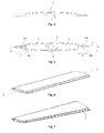
Fig. 1 shows an embodiment of the invention in which the unit consists of one single main part having cavities and openings. -
Fig. 2 shows, in perspective, the embodiment according toFig. 1 . -
Fig. 3 shows the embodiment according toFig. 1 with the twisting made permanent by welding together of the openings of the main part. -
Fig. 4 shows a main part of one embodiment in which the profile consists of more than one main part. -
Fig. 5 shows, in cross section, two main parts according toFig. 4 , brought together to a unit. -
Fig. 6 shows, in perspective, two main parts according toFig. 4 , brought together to a unit. -
Fig. 7 shows two main parts according toFig. 4 brought together with the twisting made permanent by riveting together the main parts to each other. -
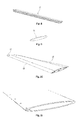
Fig. 8 shows an additional part for the side portions of the unit. -
Fig. 9 shows an additional part for the ends of the unit. -
Fig. 10 shows a into desired twisting fixed unit having two main parts according toFig. 4 and two additional parts according toFig. 8 and one additional part according toFig. 9 mounted thereon. -
Fig. 11 shows how different pieces, at the end of a unit, move relative to each other and form a step. - One, according to the invention, early step is to provide a unit 8 having one or several, along a longitudinal axis A-A, extended main part(s) 1. Different examples of said unit 8 are shown in
Fig. 1 andFig. 5 , respectively. Different examples of saidmain part 1 are shown inFig. 1 andFig. 4 , respectively. Said unit 8 has at least onelongitudinal side portion 10 which extends between opposite ends of the unit 8. In theside portions 10 there is a firstlongitudinal surface 13a which faces an opposite second longitudinal surface 13b. Saidmain parts 1 can be manufactured so that they, along its extension or their extensions, either has regarding shape and size fixed or regarding shape and/or size variable cross section profile. - An advantageous embodiment of the invention comprises that the unit 8 is formed of one single
main part 1 having at least onelongitudinal side portion 10. Such aside portion 10 shows a longitudinal slot or opening 3 lying between said firstlongitudinal surface 13a and said secondlongitudinal surface 13b. The blades illustrated inFigs. 1, 2, 3 , and11 are made according to this embodiment. - Another advantageous embodiment of the invention comprises that the unit 8, with said first
longitudinal surface 13a facing said secondlongitudinal surface 13b, is formed of two or moremain parts 1 which are brought together. Two or more of themain parts 1 may in this embodiment either be given mutually identical or mutually different cross section profiles. In the case two or moremain parts 1 are given mutually identical cross section profiles the invention gives the advantage that the manufacturing costs can be reduced since a less number of tools for the shaping process will then be necessary. Said two or moremain parts 1 may according to the invention be provided with attachment details 9 which lock together themain parts 1 without at the same time eliminate the possibility of the main parts to move relative to each other in the direction of the longitudinal axis A-A. Even such attachment details 9 can reduce the manufacturing costs since these form one, in the unit built in and for the following steps of the method, facilitating fixture. The blade illustrated inFigs. 4, 5 6, and 7 , which comprises a unit 8 composed of twomain parts 1 with attachment details 9 andside portions 10, is made according to this embodiment. - The blade according
Figs. 1, 2, and 3 has an asymmetrical cross section profile with a thicker, in the figures left part, which forms theleading edge 5a of the blade profile and a thinner, in the figures right part, which forms the trailingedge 5b of the blade profile, which, for blades which are not intended to be reversed with maintained performance, is advantageous from an aerodynamic perspective. The blades illustrated inFigs. 4, 5, 6, 7 , and11 have symmetric cross section profile which, for blades which are intended to be reversed with maintained performance, is advantageous from an aerodynamic perspective. - In a particularly preferred embodiment of the invention the unit 8 is shaped so that said first and second
longitudinal surfaces 13a-b extend up to one orseveral cavities 2 formed within in the blade.Such cavities 2 are advantageous since they on one hand reduce the weight of the blade, which reduces the demand regarding structural strength of weight carrying parts, and on the other hand gives lower consumption of material, which in its turn gives lower manufacturing costs. InFigs. 1 and5 two material andweight saving cavities 2 extend within the unit 8. Thecavities 2, which extend in major parts of the left respective right half of the blade, are connected with the area outside the unit 8 by openings 3 situated between said first and said secondlongitudinal surfaces 13a-b. - The openings 3 run along the whole extension of the unit 8 in the direction of the longitudinal axis A-A and can be shaped so that said first and said second
longitudinal surfaces 13a-b are not in contact with each other or so that they are in contact with each other, but yet have the possibility to slide against each other in the direction of the longitudinal axis A-A. The first and secondlongitudinal surfaces 13a-b may have the same shape, so that they on an extended surface fit against each other, if they are in contact with each other, or different shape, so that they only will come into contact with each other along a line in the direction of the longitudinal axis A-A. - In further particularly preferred embodiments of the invention the
main parts 1 are manufacture so that they, along their extension, are straight without twisting and/or have regarding the form and size fix cross section profile, so that a cross section through amain part 1 through a plan perpendicular to the longitudinal axis will look the same independently where along the longitudinal axis A-A the section is taken. Themain part 1, according to such embodiments, may be produced in a particularly simple way through extrusion. The invention even allows that themain parts 1 are manufactured with an initial twisting along its extension for example with the purpose that the following rotation should be able to be limited to become an adjustment of said initial twisting. Furthermore, the invention allows that themain parts 1 have regarding the shape and/or size varying cross section profile, a suitable shaping method for the main parts can then be casting. - One, according to the invention, following step is to turn the unit around the longitudinal axis A-A so that one end of the unit 8 is turned relative to the other end of the unit 8, and that the first
longitudinal surface 13a of said side portion orside portions 10 at the same time move relative to the opposite secondlongitudinal surface 13b in the direction of said longitudinal axis A-A. This step may be performed so that the twisting is either distributed evenly or unevenly along the extension of the unit 8. Abridge 7 extends along the longitudinal axis A-A inFig. 1 , which bridge connects the material at thepressure side 4b of the profile with the material of thesuction side 4a of the profile, and in this way a unit 8 is formed with twocavities 2 separated from each other. Also inFig. 5 a unit 8 is formed with twocavities 2 separated from each other when themain parts 1 are attached by the attachment details 9. When a moment is applied along the longitudinal axis A-A of the unit 8, according to any of theFigs. 1 or5 , the firstlongitudinal surface 13a will move relative to the secondlongitudinal surface 13b in the direction of the longitudinal axis A-A at bothside portions 10 of the profile. - One according to the invention late step is to fixate said opposite first and second
longitudinal surfaces 13a-b into each other in their, as a consequence of said turning relative to each other, new positions obtained and hereby make permanent the achieved twisting. InFigs. 1 and4 , respectively, the first and second longitudinal surfaces 13-b are not attached and the unit 8 would therefore spontaneously turn back to the straight shapes illustrated inFigs. 2 and6 , respectively, if such a twisting moment is removed. The fixation can be made in different ways, for instance by cwelding, riveting, upsetting, gluing or screwing. InFig. 3 the desired twisting is shown made permanent by welding 6 together and inFig. 7 by riveting 11 together of the first and second longitudinal surfaces 13-b of the unit to each other. - According to one embodiment of the invention the unit 8 is supplemented with one or several
additional parts 12 which are arranged towards themain part 1 of the unit 8. Such supplementaryadditional parts 12 may extend in the direction of the longitudinal axis A-A and be arranged against theside portions 10 of themain parts 1, for instance with the purpose of forming a portion of the exterior shape of the blade and/or to protect any part of theside portions 10 against exposure. Alternatively, supplementaryadditional parts 12 can be arranged towards the ends of themain parts 1 and then work as finishing parts. Such finishing parts can for instance form sealings, which on one hand protectinner cavities 2 of the unit 8 against exposure of impurities and on the other hand eliminate undesired flows of fluid within the unit 8. Saidadditional parts 12 may be manufacture so that they, along their extension, either have to form and shape fix or to form and/or size variable cross section profile. In the case they have fix cross section profile extrusion is an advantageous method of shaping. In the case the unit 8 is supplemented with more than oneadditional part 12 two or more of theadditional parts 12 may in certain cases be given a mutual identical cross section profile and then obtain the advantage that the manufacturing costs can be reduced since less tools for the manufacturing method will be necessary. In view of the design of themain part 1 and of theadditional part 12 and in view of the design of methods for turning and mounting on, theadditional part 12 may be mounted on the unit 8 at the moment which is best suited; before, during or after turning of the unit 8. In the case the mounting of possibleadditional parts 12 is made before the turning of the unit 8, the attachment of the additional unit 8 can be performed simultaneously as the first and the secondlongitudinal surfaces 13a-b of the unit are fixated to each other in their relative to each other new positions. - The
additional part 12 illustrated inFig. 8 has a cross section which to its shape fits against, and may be pushed on to theside portions 10 of the main parts illustrated inFig. 5 and may in this way on one hand form a portion of the external shape of the blade and on the other hand protect the joint 11 against exposing. - The
additional part 12 according toFig. 9 has a shape where the circumference corresponds to the external shape of the profile of the blade, and may, when it is mounted to the end of the blade, function as a sealing and then on one hand protect theinner cavities 2 of the unit 8 against exposing towards impurities and on the other hand eliminate unwanted flows of fluid within the unit 8. It should be mentioned that the invention is not limited to the forms of theadditional part 12 as illustrated and combinations of themain part 1 and theadditional part 12 as illustrated. - The symmetrical unit 8 illustrated in
Fig. 10 is made up of two portions which are identical and along its extension uniformmain parts 1. At bothside portions 10 of the unit 8 and at one end of the unit 8additional parts 12 are arranged. The unit 8 is turned to the desired twisting. Theparts 1 mounted together and turned according to the figure form a complete blade which is ready to be mounted on a hub to a reversible axial fan.
Claims (15)
- Method for manufacturing blades to flow machines of axial type, such as axial fans, comprising the steps of:providing a unit (8) which has at least one along a longitudinal axis (A-A) extended main part (1), which unit (8) has at least one longitudinal side portion (10) extending between two opposite ends of the unit (8), each side portion (10) comprising a first longitudinal surface (13a) facing an opposite second longitudinal surface (13b),turning one end of the unit (8) around the longitudinal axis relative to another end of the unit (8) so that the first longitudinal surface (13a) of said side portion or side portions (10) moves/move relative to the opposite second longitudinal surface (13b) in the direction of said longitudinal axis (A-A), andafter turning to desired angle difference between both ends of the unit (8), fixation of the first longitudinal surface (13a) of said side portion or side portions (10) in its new, relative to the opposite second longitudinal surface (13b) of the side portion (10), position, whereby the achieved twisting is made permanent.
- Method according to claim 1, wherein said main part (1) is manufactured along it extension or their extensions with fix cross section profiles.
- Method according to claim 1 or 2, wherein said step of providing a unit (8) comprises providing and bringing together two or more main parts (1) which brought together form a unit (8) presenting said first longitudinal surface (13a) facing said second longitudinal surface (13b).
- Method according to claim 3, wherein two or more of said main parts (1) are given mutually identical cross section profiles.
- Method according to claim 3 or 4, wherein the step of providing a unit (8) comprises providing said main part (1) with attachment details (9), where the attachment details (9) lock together the main parts (1) without simultaneously eliminating the possibility of the main parts (1) to move relative to each other in the direction of the longitudinal axis (A-A).
- Method according to claim 1 or 2, wherein said step of providing a unit (8) comprises providing only one main part (1) which in at least one longitudinal side portion (10) shows a longitudinal slot or opening (3), which slot/opening (3) is situated between said first longitudinal surface (13a) and said second longitudinal surface (13b).
- Method according to anyone of the preceding claims, further comprising arranging at least one supplementary addition part (12) against the unit (8), and wherein said supplementary additional part (12), extended in the direction of the longitudinal axis (A-A), is arranged towards the side portions (10) of said unit (8).
- Method according to claim 7, wherein said additional part (12) is manufactured with, along its extensions, fix cross section profiles, and wherein said additional parts (12) are manufactured by extrusion.
- Method according to claim 7 or 8, wherein the additional parts (12), which are arranged at different positions in the unit (8), have mutually identical cross section profiles.
- Method according to anyone of the preceding claims, wherein said step of providing a unit (8) comprises, before turning, providing one totally straight or several totally straight main part(s) (1) without twisting.
- Method according to anyone of the preceding claims, wherein said step of providing a unit (8) comprises producing said first longitudinal surface (13a) and said second longitudinal surface (13b) so that they extend into at least one cavity (2) formed in the blade.
- Method according to anyone of the preceding claims, wherein said step of providing a unit (8) comprises producing said main part (1) by extrusion.
- Method according to anyone of the preceding claims, wherein the steps of fixating said first and said second longitudinal surfaces (13a-b) towards each other comprises that said surfaces are welded, riveted, upsetted, glued or screwed to each other.
- Blade for flow machines of axial type, such as axial fans, manufactured according to the method according to anyone of claims 1-13.
- Rotor for flow machines of axial type, such as axial fans, comprising a set of blades arranged around a hub, where said blades are manufactured according to the method according to anyone of claims 1-13.
Priority Applications (1)
| Application Number | Priority Date | Filing Date | Title |
|---|---|---|---|
| PL14167531T PL2801437T3 (en) | 2013-05-08 | 2014-05-08 | Method for manufactureing blades for axial flow machines |
Applications Claiming Priority (1)
| Application Number | Priority Date | Filing Date | Title |
|---|---|---|---|
| SE1300323A SE537001C2 (en) | 2013-05-08 | 2013-05-08 | Blades for axial type turbomachines and process for manufacturing such blades |
Publications (3)
| Publication Number | Publication Date |
|---|---|
| EP2801437A2 true EP2801437A2 (en) | 2014-11-12 |
| EP2801437A3 EP2801437A3 (en) | 2014-12-17 |
| EP2801437B1 EP2801437B1 (en) | 2019-06-26 |
Family
ID=50679925
Family Applications (1)
| Application Number | Title | Priority Date | Filing Date |
|---|---|---|---|
| EP14167531.4A Active EP2801437B1 (en) | 2013-05-08 | 2014-05-08 | Method for manufactureing blades for axial flow machines |
Country Status (4)
| Country | Link |
|---|---|
| EP (1) | EP2801437B1 (en) |
| DK (1) | DK2801437T3 (en) |
| PL (1) | PL2801437T3 (en) |
| SE (1) | SE537001C2 (en) |
Cited By (1)
| Publication number | Priority date | Publication date | Assignee | Title |
|---|---|---|---|---|
| CN113685363A (en) * | 2020-05-18 | 2021-11-23 | 中国航发商用航空发动机有限责任公司 | Multi-stage axial flow compressor blade design method |
Family Cites Families (6)
| Publication number | Priority date | Publication date | Assignee | Title |
|---|---|---|---|---|
| US2514525A (en) * | 1944-03-09 | 1950-07-11 | Curtiss Wright Corp | Method of producing blade constructions and propeller blades |
| GB713690A (en) * | 1951-02-23 | 1954-08-18 | Escher Wyss Ag | Improvements in and relating to blades for turbines and similar machines |
| FR1144946A (en) * | 1955-03-31 | 1957-10-18 | Escher Wyss Ag | Method for twisting a hollow vane intended for axial flow turbo-machines and the hollow vane for implementing this method |
| US3052961A (en) * | 1960-02-04 | 1962-09-11 | Alden O Sherman | Method of forming hollow vanes and blades for gas turbines |
| GB1089247A (en) * | 1966-06-03 | 1967-11-01 | Rolls Royce | Method of manufacturing a hollow aerofoil section blade for a fluid flow machine |
| HU178353B (en) * | 1979-10-25 | 1982-04-28 | Szelloezoe Muevek | Wing or blade composed from parts for fans or fanlike machines |
-
2013
- 2013-05-08 SE SE1300323A patent/SE537001C2/en not_active IP Right Cessation
-
2014
- 2014-05-08 PL PL14167531T patent/PL2801437T3/en unknown
- 2014-05-08 DK DK14167531.4T patent/DK2801437T3/en active
- 2014-05-08 EP EP14167531.4A patent/EP2801437B1/en active Active
Non-Patent Citations (1)
| Title |
|---|
| None |
Cited By (1)
| Publication number | Priority date | Publication date | Assignee | Title |
|---|---|---|---|---|
| CN113685363A (en) * | 2020-05-18 | 2021-11-23 | 中国航发商用航空发动机有限责任公司 | Multi-stage axial flow compressor blade design method |
Also Published As
| Publication number | Publication date |
|---|---|
| DK2801437T3 (en) | 2019-08-19 |
| EP2801437A3 (en) | 2014-12-17 |
| EP2801437B1 (en) | 2019-06-26 |
| SE1300323A1 (en) | 2014-11-09 |
| PL2801437T3 (en) | 2020-02-28 |
| SE537001C2 (en) | 2014-11-25 |
Similar Documents
| Publication | Publication Date | Title |
|---|---|---|
| US9017038B2 (en) | Variable performance vaneaxial fan with high efficiency | |
| EP2877701B1 (en) | Turbocharger impeller | |
| US8485787B2 (en) | Turbine airfoil fabricated from tapered extrusions | |
| US9120144B2 (en) | Casting core for twisted gas turbine engine airfoil having a twisted rib | |
| CN105008668A (en) | Twisted gas turbine engine airfoil having a twisted rib | |
| EP0816637B1 (en) | Gas turbine guide vane | |
| EP2441964B1 (en) | Airfoil design method for an axial compressor and axial compressor | |
| WO2007144563A1 (en) | A stringer for an aircraft wing and a method of forming thereof | |
| US20090194636A1 (en) | Stringer for an aircraft wing and a method of forming thereof | |
| CA2962733C (en) | Stator-vane structure and turbofan engine employing the same | |
| CA2862719C (en) | Shrouded rotary assembly from segmented composite for aircraft | |
| CA2896164A1 (en) | Guide vane assembly vane box of an axial turbine engine compressor | |
| EP2801437B1 (en) | Method for manufactureing blades for axial flow machines | |
| US5619797A (en) | Flow-straightener vane for counter-torque device with ducted rotor and ducted flow-straightening stator, for helicopter | |
| EP2994615B1 (en) | Rotor for a thermal turbomachine | |
| EP2827003B1 (en) | Gas turbine compressor guide vane assembly | |
| EP3704386B1 (en) | Intermediate duct to be placed between a low pressure compressor and a high pressure compressor, made by additive manufacturing, and corresponding manufacturing method | |
| EP2896788B1 (en) | Extruded profile for producing a guide vane and fabrication method | |
| EP3784909A1 (en) | Outlet guide device for an axial fan | |
| CN211370828U (en) | Axial-flow type aircraft engine and disc shaft structure thereof | |
| US11346361B2 (en) | One piece casting fan hub and method of manufacture a fan | |
| CN111795126A (en) | Stator for a hydrodynamic torque converter and hydrodynamic torque converter comprising such a stator | |
| WO2023062578A1 (en) | Blade for a low-noise industrial axial fan, industrial axial fan and process for manufacturing a blade of an industrial axial fan | |
| RU2597324C1 (en) | Impeller blade of rotor of compressor of low-pressure gas turbine (versions) | |
| IT202100020579A1 (en) | INDUSTRIAL AXIAL FAN |
Legal Events
| Date | Code | Title | Description |
|---|---|---|---|
| PUAI | Public reference made under article 153(3) epc to a published international application that has entered the european phase |
Free format text: ORIGINAL CODE: 0009012 |
|
| 17P | Request for examination filed |
Effective date: 20140508 |
|
| AK | Designated contracting states |
Kind code of ref document: A2 Designated state(s): AL AT BE BG CH CY CZ DE DK EE ES FI FR GB GR HR HU IE IS IT LI LT LU LV MC MK MT NL NO PL PT RO RS SE SI SK SM TR |
|
| AX | Request for extension of the european patent |
Extension state: BA ME |
|
| PUAL | Search report despatched |
Free format text: ORIGINAL CODE: 0009013 |
|
| AK | Designated contracting states |
Kind code of ref document: A3 Designated state(s): AL AT BE BG CH CY CZ DE DK EE ES FI FR GB GR HR HU IE IS IT LI LT LU LV MC MK MT NL NO PL PT RO RS SE SI SK SM TR |
|
| AX | Request for extension of the european patent |
Extension state: BA ME |
|
| RIC1 | Information provided on ipc code assigned before grant |
Ipc: F01D 5/14 20060101ALI20141110BHEP Ipc: F04D 29/38 20060101ALI20141110BHEP Ipc: B23P 15/02 20060101AFI20141110BHEP |
|
| R17P | Request for examination filed (corrected) |
Effective date: 20150615 |
|
| RBV | Designated contracting states (corrected) |
Designated state(s): AL AT BE BG CH CY CZ DE DK EE ES FI FR GB GR HR HU IE IS IT LI LT LU LV MC MK MT NL NO PL PT RO RS SE SI SK SM TR |
|
| STAA | Information on the status of an ep patent application or granted ep patent |
Free format text: STATUS: EXAMINATION IS IN PROGRESS |
|
| 17Q | First examination report despatched |
Effective date: 20180305 |
|
| GRAP | Despatch of communication of intention to grant a patent |
Free format text: ORIGINAL CODE: EPIDOSNIGR1 |
|
| STAA | Information on the status of an ep patent application or granted ep patent |
Free format text: STATUS: GRANT OF PATENT IS INTENDED |
|
| RIC1 | Information provided on ipc code assigned before grant |
Ipc: B23P 15/02 20060101AFI20181130BHEP Ipc: F04D 29/38 20060101ALI20181130BHEP Ipc: F01D 5/14 20060101ALI20181130BHEP Ipc: F04D 29/02 20060101ALI20181130BHEP Ipc: F04D 29/32 20060101ALI20181130BHEP |
|
| INTG | Intention to grant announced |
Effective date: 20190109 |
|
| GRAS | Grant fee paid |
Free format text: ORIGINAL CODE: EPIDOSNIGR3 |
|
| GRAA | (expected) grant |
Free format text: ORIGINAL CODE: 0009210 |
|
| STAA | Information on the status of an ep patent application or granted ep patent |
Free format text: STATUS: THE PATENT HAS BEEN GRANTED |
|
| AK | Designated contracting states |
Kind code of ref document: B1 Designated state(s): AL AT BE BG CH CY CZ DE DK EE ES FI FR GB GR HR HU IE IS IT LI LT LU LV MC MK MT NL NO PL PT RO RS SE SI SK SM TR |
|
| REG | Reference to a national code |
Ref country code: GB Ref legal event code: FG4D |
|
| REG | Reference to a national code |
Ref country code: CH Ref legal event code: EP |
|
| REG | Reference to a national code |
Ref country code: AT Ref legal event code: REF Ref document number: 1147748 Country of ref document: AT Kind code of ref document: T Effective date: 20190715 |
|
| REG | Reference to a national code |
Ref country code: DE Ref legal event code: R096 Ref document number: 602014048974 Country of ref document: DE |
|
| REG | Reference to a national code |
Ref country code: IE Ref legal event code: FG4D |
|
| REG | Reference to a national code |
Ref country code: DK Ref legal event code: T3 Effective date: 20190816 |
|
| REG | Reference to a national code |
Ref country code: NL Ref legal event code: MP Effective date: 20190626 |
|
| PG25 | Lapsed in a contracting state [announced via postgrant information from national office to epo] |
Ref country code: AL Free format text: LAPSE BECAUSE OF FAILURE TO SUBMIT A TRANSLATION OF THE DESCRIPTION OR TO PAY THE FEE WITHIN THE PRESCRIBED TIME-LIMIT Effective date: 20190626 Ref country code: SE Free format text: LAPSE BECAUSE OF FAILURE TO SUBMIT A TRANSLATION OF THE DESCRIPTION OR TO PAY THE FEE WITHIN THE PRESCRIBED TIME-LIMIT Effective date: 20190626 Ref country code: FI Free format text: LAPSE BECAUSE OF FAILURE TO SUBMIT A TRANSLATION OF THE DESCRIPTION OR TO PAY THE FEE WITHIN THE PRESCRIBED TIME-LIMIT Effective date: 20190626 Ref country code: NO Free format text: LAPSE BECAUSE OF FAILURE TO SUBMIT A TRANSLATION OF THE DESCRIPTION OR TO PAY THE FEE WITHIN THE PRESCRIBED TIME-LIMIT Effective date: 20190926 Ref country code: HR Free format text: LAPSE BECAUSE OF FAILURE TO SUBMIT A TRANSLATION OF THE DESCRIPTION OR TO PAY THE FEE WITHIN THE PRESCRIBED TIME-LIMIT Effective date: 20190626 Ref country code: LT Free format text: LAPSE BECAUSE OF FAILURE TO SUBMIT A TRANSLATION OF THE DESCRIPTION OR TO PAY THE FEE WITHIN THE PRESCRIBED TIME-LIMIT Effective date: 20190626 |
|
| REG | Reference to a national code |
Ref country code: LT Ref legal event code: MG4D |
|
| PG25 | Lapsed in a contracting state [announced via postgrant information from national office to epo] |
Ref country code: LV Free format text: LAPSE BECAUSE OF FAILURE TO SUBMIT A TRANSLATION OF THE DESCRIPTION OR TO PAY THE FEE WITHIN THE PRESCRIBED TIME-LIMIT Effective date: 20190626 Ref country code: RS Free format text: LAPSE BECAUSE OF FAILURE TO SUBMIT A TRANSLATION OF THE DESCRIPTION OR TO PAY THE FEE WITHIN THE PRESCRIBED TIME-LIMIT Effective date: 20190626 Ref country code: BG Free format text: LAPSE BECAUSE OF FAILURE TO SUBMIT A TRANSLATION OF THE DESCRIPTION OR TO PAY THE FEE WITHIN THE PRESCRIBED TIME-LIMIT Effective date: 20190926 Ref country code: GR Free format text: LAPSE BECAUSE OF FAILURE TO SUBMIT A TRANSLATION OF THE DESCRIPTION OR TO PAY THE FEE WITHIN THE PRESCRIBED TIME-LIMIT Effective date: 20190927 |
|
| REG | Reference to a national code |
Ref country code: AT Ref legal event code: MK05 Ref document number: 1147748 Country of ref document: AT Kind code of ref document: T Effective date: 20190626 |
|
| PG25 | Lapsed in a contracting state [announced via postgrant information from national office to epo] |
Ref country code: NL Free format text: LAPSE BECAUSE OF FAILURE TO SUBMIT A TRANSLATION OF THE DESCRIPTION OR TO PAY THE FEE WITHIN THE PRESCRIBED TIME-LIMIT Effective date: 20190626 Ref country code: AT Free format text: LAPSE BECAUSE OF FAILURE TO SUBMIT A TRANSLATION OF THE DESCRIPTION OR TO PAY THE FEE WITHIN THE PRESCRIBED TIME-LIMIT Effective date: 20190626 Ref country code: EE Free format text: LAPSE BECAUSE OF FAILURE TO SUBMIT A TRANSLATION OF THE DESCRIPTION OR TO PAY THE FEE WITHIN THE PRESCRIBED TIME-LIMIT Effective date: 20190626 Ref country code: SK Free format text: LAPSE BECAUSE OF FAILURE TO SUBMIT A TRANSLATION OF THE DESCRIPTION OR TO PAY THE FEE WITHIN THE PRESCRIBED TIME-LIMIT Effective date: 20190626 Ref country code: RO Free format text: LAPSE BECAUSE OF FAILURE TO SUBMIT A TRANSLATION OF THE DESCRIPTION OR TO PAY THE FEE WITHIN THE PRESCRIBED TIME-LIMIT Effective date: 20190626 Ref country code: PT Free format text: LAPSE BECAUSE OF FAILURE TO SUBMIT A TRANSLATION OF THE DESCRIPTION OR TO PAY THE FEE WITHIN THE PRESCRIBED TIME-LIMIT Effective date: 20191028 |
|
| PG25 | Lapsed in a contracting state [announced via postgrant information from national office to epo] |
Ref country code: SM Free format text: LAPSE BECAUSE OF FAILURE TO SUBMIT A TRANSLATION OF THE DESCRIPTION OR TO PAY THE FEE WITHIN THE PRESCRIBED TIME-LIMIT Effective date: 20190626 Ref country code: IS Free format text: LAPSE BECAUSE OF FAILURE TO SUBMIT A TRANSLATION OF THE DESCRIPTION OR TO PAY THE FEE WITHIN THE PRESCRIBED TIME-LIMIT Effective date: 20191026 Ref country code: ES Free format text: LAPSE BECAUSE OF FAILURE TO SUBMIT A TRANSLATION OF THE DESCRIPTION OR TO PAY THE FEE WITHIN THE PRESCRIBED TIME-LIMIT Effective date: 20190626 |
|
| PG25 | Lapsed in a contracting state [announced via postgrant information from national office to epo] |
Ref country code: TR Free format text: LAPSE BECAUSE OF FAILURE TO SUBMIT A TRANSLATION OF THE DESCRIPTION OR TO PAY THE FEE WITHIN THE PRESCRIBED TIME-LIMIT Effective date: 20190626 |
|
| PG25 | Lapsed in a contracting state [announced via postgrant information from national office to epo] |
Ref country code: IS Free format text: LAPSE BECAUSE OF FAILURE TO SUBMIT A TRANSLATION OF THE DESCRIPTION OR TO PAY THE FEE WITHIN THE PRESCRIBED TIME-LIMIT Effective date: 20200224 |
|
| REG | Reference to a national code |
Ref country code: DE Ref legal event code: R097 Ref document number: 602014048974 Country of ref document: DE |
|
| PLBE | No opposition filed within time limit |
Free format text: ORIGINAL CODE: 0009261 |
|
| STAA | Information on the status of an ep patent application or granted ep patent |
Free format text: STATUS: NO OPPOSITION FILED WITHIN TIME LIMIT |
|
| PG2D | Information on lapse in contracting state deleted |
Ref country code: IS |
|
| 26N | No opposition filed |
Effective date: 20200603 |
|
| PG25 | Lapsed in a contracting state [announced via postgrant information from national office to epo] |
Ref country code: SI Free format text: LAPSE BECAUSE OF FAILURE TO SUBMIT A TRANSLATION OF THE DESCRIPTION OR TO PAY THE FEE WITHIN THE PRESCRIBED TIME-LIMIT Effective date: 20190626 |
|
| PG25 | Lapsed in a contracting state [announced via postgrant information from national office to epo] |
Ref country code: MC Free format text: LAPSE BECAUSE OF FAILURE TO SUBMIT A TRANSLATION OF THE DESCRIPTION OR TO PAY THE FEE WITHIN THE PRESCRIBED TIME-LIMIT Effective date: 20190626 Ref country code: CH Free format text: LAPSE BECAUSE OF NON-PAYMENT OF DUE FEES Effective date: 20200531 Ref country code: LI Free format text: LAPSE BECAUSE OF NON-PAYMENT OF DUE FEES Effective date: 20200531 |
|
| REG | Reference to a national code |
Ref country code: BE Ref legal event code: MM Effective date: 20200531 |
|
| GBPC | Gb: european patent ceased through non-payment of renewal fee |
Effective date: 20200508 |
|
| PG25 | Lapsed in a contracting state [announced via postgrant information from national office to epo] |
Ref country code: LU Free format text: LAPSE BECAUSE OF NON-PAYMENT OF DUE FEES Effective date: 20200508 |
|
| PG25 | Lapsed in a contracting state [announced via postgrant information from national office to epo] |
Ref country code: IE Free format text: LAPSE BECAUSE OF NON-PAYMENT OF DUE FEES Effective date: 20200508 Ref country code: GB Free format text: LAPSE BECAUSE OF NON-PAYMENT OF DUE FEES Effective date: 20200508 Ref country code: FR Free format text: LAPSE BECAUSE OF NON-PAYMENT OF DUE FEES Effective date: 20200531 |
|
| PG25 | Lapsed in a contracting state [announced via postgrant information from national office to epo] |
Ref country code: BE Free format text: LAPSE BECAUSE OF NON-PAYMENT OF DUE FEES Effective date: 20200531 |
|
| PG25 | Lapsed in a contracting state [announced via postgrant information from national office to epo] |
Ref country code: MT Free format text: LAPSE BECAUSE OF FAILURE TO SUBMIT A TRANSLATION OF THE DESCRIPTION OR TO PAY THE FEE WITHIN THE PRESCRIBED TIME-LIMIT Effective date: 20190626 Ref country code: CY Free format text: LAPSE BECAUSE OF FAILURE TO SUBMIT A TRANSLATION OF THE DESCRIPTION OR TO PAY THE FEE WITHIN THE PRESCRIBED TIME-LIMIT Effective date: 20190626 |
|
| PG25 | Lapsed in a contracting state [announced via postgrant information from national office to epo] |
Ref country code: MK Free format text: LAPSE BECAUSE OF FAILURE TO SUBMIT A TRANSLATION OF THE DESCRIPTION OR TO PAY THE FEE WITHIN THE PRESCRIBED TIME-LIMIT Effective date: 20190626 |
|
| PGFP | Annual fee paid to national office [announced via postgrant information from national office to epo] |
Ref country code: IT Payment date: 20220421 Year of fee payment: 9 Ref country code: DE Payment date: 20220421 Year of fee payment: 9 |
|
| PGFP | Annual fee paid to national office [announced via postgrant information from national office to epo] |
Ref country code: DK Payment date: 20230424 Year of fee payment: 10 Ref country code: CZ Payment date: 20230424 Year of fee payment: 10 |
|
| PGFP | Annual fee paid to national office [announced via postgrant information from national office to epo] |
Ref country code: PL Payment date: 20230424 Year of fee payment: 10 |
|
| REG | Reference to a national code |
Ref country code: DE Ref legal event code: R119 Ref document number: 602014048974 Country of ref document: DE |
|
| PG25 | Lapsed in a contracting state [announced via postgrant information from national office to epo] |
Ref country code: IT Free format text: LAPSE BECAUSE OF NON-PAYMENT OF DUE FEES Effective date: 20230508 Ref country code: DE Free format text: LAPSE BECAUSE OF NON-PAYMENT OF DUE FEES Effective date: 20231201 |