EP2800942B1 - Gun sight for use with superelevating weapon - Google Patents
Gun sight for use with superelevating weapon Download PDFInfo
- Publication number
- EP2800942B1 EP2800942B1 EP12869494.0A EP12869494A EP2800942B1 EP 2800942 B1 EP2800942 B1 EP 2800942B1 EP 12869494 A EP12869494 A EP 12869494A EP 2800942 B1 EP2800942 B1 EP 2800942B1
- Authority
- EP
- European Patent Office
- Prior art keywords
- imaging system
- weapon
- inclinometer
- angular orientation
- gun sight
- Prior art date
- Legal status (The legal status is an assumption and is not a legal conclusion. Google has not performed a legal analysis and makes no representation as to the accuracy of the status listed.)
- Active
Links
Images


Classifications
-
- F—MECHANICAL ENGINEERING; LIGHTING; HEATING; WEAPONS; BLASTING
- F41—WEAPONS
- F41G—WEAPON SIGHTS; AIMING
- F41G1/00—Sighting devices
-
- F—MECHANICAL ENGINEERING; LIGHTING; HEATING; WEAPONS; BLASTING
- F41—WEAPONS
- F41G—WEAPON SIGHTS; AIMING
- F41G3/00—Aiming or laying means
- F41G3/14—Indirect aiming means
- F41G3/16—Sighting devices adapted for indirect laying of fire
- F41G3/165—Sighting devices adapted for indirect laying of fire using a TV-monitor
-
- F—MECHANICAL ENGINEERING; LIGHTING; HEATING; WEAPONS; BLASTING
- F41—WEAPONS
- F41G—WEAPON SIGHTS; AIMING
- F41G1/00—Sighting devices
- F41G1/46—Sighting devices for particular applications
- F41G1/473—Sighting devices for particular applications for lead-indicating or range-finding, e.g. for use with rifles or shotguns
-
- F—MECHANICAL ENGINEERING; LIGHTING; HEATING; WEAPONS; BLASTING
- F41—WEAPONS
- F41G—WEAPON SIGHTS; AIMING
- F41G1/00—Sighting devices
- F41G1/46—Sighting devices for particular applications
- F41G1/50—Sighting devices for particular applications for trench mortars or for other mortars
-
- F—MECHANICAL ENGINEERING; LIGHTING; HEATING; WEAPONS; BLASTING
- F41—WEAPONS
- F41G—WEAPON SIGHTS; AIMING
- F41G3/00—Aiming or laying means
-
- F—MECHANICAL ENGINEERING; LIGHTING; HEATING; WEAPONS; BLASTING
- F41—WEAPONS
- F41G—WEAPON SIGHTS; AIMING
- F41G3/00—Aiming or laying means
- F41G3/06—Aiming or laying means with rangefinder
Definitions
- the present invention generally relates to weapons and more particularly to a gun sight for use with a weapon configured for superelevation.
- a gun sight that is coupled with a display that presents an image of a down range area that includes the target.
- An aiming reticle is often displayed on the display, the position of which is calculated by a ballistic algorithm, to assist the operator in aiming the weapon and engaging a target down range.
- Modern gun sights have high levels of magnification that permit precise aiming of the weapon at long ranges. Such gun sights provide a field of view of only a few degrees. When a targeting solution is determined that requires superelevation, the gun sight may be elevated together with the weapon and the target will very likely move off of the display when the required superelevation exceeds the field of view. This loss of visual contact with the target during superelevation is undesirable.
- Lougheed describes a grenade machine gun or other weapon that employs superelevation of the barrel and an aiming system.
- the aiming system is mounted to both the weapon and the weapon's support or base.
- the aiming system is configured to alternatively lock to either the weapon or to the weapon's support.
- the aiming system When locked to the weapon, the aiming system is free to rotate in elevation and azimuth in unison with the weapon.
- the aiming system is restrained from elevation and thus the weapon can be superelevated while the aiming system remains oriented at a static elevation angle. In this manner, the weapon can be superelevated yet still allow an operator to maintain visual contact with the target on the display.
- Lougheed's aiming system is large and has substantial mass. Additionally, systems constructed in accordance with Lougheed's disclosure have historically been very expensive. Also, in some circumstances, it may not be sufficient or desirable to lock the aiming system into a static elevation angle with respect to the weapon support. For example, the terrain may be sandy or muddy or otherwise unstable. On such terrain, superelevation of the weapon or other circumstances may cause the weapon support to shift. This, in turn, would cause an unintended deviation of the aiming system and possibly a loss of line of sight to the target. Furthermore, by having the gun sight attach to the weapon mount, the gun sight is less adaptable for use with different weapons.
- EP 2 275 769 A2 describes a fire guidance device for a hand fired weapon suitable for large caliber and slow flying ammunition or missiles.
- the fire guidance device adjusts the set-up angle for adjustments of ballistics and a lateral angle for spin correction.
- GB 1 294 291 A describes a method and system for establishing a correct lead when firing at a moving target, while the lead results from a lateral movement of the target.
- DE1946972 A1 refers to a weapon sighting and correcting device for a flat shooter including a Wheatstone bridge forming an equalizing circuit between the line of sight (3) and the axis (4) of the weapon (1) with a variable resistance (7) connected to the sight (2) in one arm of the bridge. Two other opposite arms include further variable resistances (10, 11) for e. g.
- the fourth arm includes a ring shaped resistance (13) inside a tube (12) with an electrical connection formed by a mercury globule (14). Its position varies with that of the weapon axis (1).
- an indicator device with an amplifier (15) and two indicator lamps (16, 17).
- DE 102005007910 A1 refers to a firearm for long flight duration projectiles, such as a grenade launcher, having a barrel (18) and a fire guidance system (24) including a sight (26) and sensors to acquire target data (44).
- the sight line longitudinal axis can be adjusted around a preset angle in dependence on the acquired data.
- the sight can also be adjusted relative to the bore of the barrel.
- a gun sight comprising the features of claim 1 for use with a weapon configured for superelevation.
- the weapon may include an angle measuring device configured to measure both an angular orientation of the weapon and a change in an angular orientation of the weapon.
- Advantageous embodiments of the gun sight can be derived from the subclaims.
- the gun sight as specified in independent claim 1 includes an imaging system configured for rotation in elevation.
- the gun sight further includes a drive mechanism associated with the imaging system and configured to rotate the imaging system.
- the gun sight further includes an inclinometer associated with one of the weapon and the imaging system.
- the gun sight still further includes a processor communicatively coupled with the drive mechanism and the inclinometer and configured to control the drive mechanism to rotate the imaging system in an iterative manner throughout the period when the weapon is being superelevated such it exceeds the field of view of the imaging system, causing the angular orientation of the imaging system to be repeatedly adjusted in a manner that offsets rotation of the weapon to cause the imaging system to maintain an initial angular orientation based, at least in part, on information provided by the inclinometer.
- An improved gun sight is disclosed herein that is configured to maintain a line of sight to the target during superelevation of the weapon.
- the gun sight or a portion of the gun sight, is configured to rotate with respect to the weapon.
- the gun sight utilizes a processor, an inclinometer, and a drive mechanism to steady itself at an elevation that aligns the gun sight with a line of sight to a target.
- the gun sight is mounted to the weapon and will rotate together with the weapon in azimuth and will further rotate together with the weapon elevation during non-superelevating changes in elevation of the weapon.
- the processor When superelevation is initiated, the processor will use information that is provided by the inclinometer to operate the drive mechanism to rotate the gun sight, or a portion of the gun sight, in a manner that offsets the rotation of the superelevating weapon, thereby allowing the gun sight to maintain a line of sight to the target.
- the inclinometer may be mounted to the gun sight.
- the gun sight When superelevation is initiated, the gun sight will detect its initial angular orientation and the processor will obtain the initial angular orientation from the inclinometer.
- the inclinometer As the weapon is superelevated, the inclinometer will detect a deviation of the gun sight from the initial angular orientation.
- the processor receives information from the inclinometer indicative of the deviation of the gun sight from the initial angular orientation, the processor will instruct the drive mechanism to rotate the gun sight, or a portion of the gun sight, in a manner that offsets the deviation and that maintains the gun sight at the initial angular orientation and, as a result, directs the gun sight's line of sight to the target.
- the inclinometer may be mounted to the weapon and will detect the angular orientation of the weapon.
- the weapon will include an additional angle measuring device that is used to provide elevation information to the weapon's fire control system for use in calculating a firing solution.
- the additional angle measuring device will measure the angle between the weapon and the gun sight's line of sight (i.e., the superelevation angle).
- the superelevation angle As the weapon is superelevated, changes in the angular orientation of the weapon will be detected by the inclinometer. Changes in the elevation of the weapon will be measured by the angle measuring device.
- the inclinometer and the angle measuring device will provide information to the processor that indicates that a deviation in the angular orientation of the weapon has occurred and the amount of such deviation.
- the processor will use this information to control the drive mechanism to rotate the gun sight, or a portion thereof, in a manner that maintains the gun sight at a desired angular orientation that provides the gun sight with a line of sight to the target.
- FIG. 1 is a block diagram illustrating a non-limiting embodiment of a gun sight 10, made in accordance with the teachings of the present disclosure.
- Gun sight 10 may be adapted for mounting to weapon 12 such that gun sight 10 rotates in azimuth together with weapon 12 and also rotates in elevation together with weapon 12 at times other than when weapon 12 is being superelevated.
- the operator is able to both rotate and elevate weapon 12 while looking through a view finder displaying images captured by gun sight 10, allowing the operator to identify and select targets downrange.
- weapon 12 and gun sight 10 may be bore sighted such that weapon 12 and gun sight 10 remain optically locked together in an aligned position, such that the weapon and the gun sight remain pointing at a single down range location.
- Weapon 12 may be any weapon that utilizes superelevation including, but not limited to mortar launchers, grenade launchers, machine grenade launchers, artillery, rifles, machine guns, and the like.
- Gun sight 10 includes an imaging system 14, a drive mechanism 16, an inclinometer 18, and a processor 20.
- gun sight 10 may include a greater number of components without departing from the teachings of the present disclosure.
- each of the components of gun sight 10 may be enclosed in a single housing, while in other embodiments, only some of the components may be contained within a housing. In still other embodiments, each of the components may be housed separately.
- the components of gun sight 10 may be used exclusively by gun sight 10 while in other embodiments, one or more components may be shared with weapon 12 or some other device.
- Imaging system 14 may comprise any suitable imaging system including, without limitation, a daytime imaging system (e.g., a video camera, television camera), a thermal imaging system, an infrared imaging system, a laser range finder, a radar system, a sonar system, or any other type of system that is configured to perceive and/or detect the presence of an object at a downrange location.
- imaging system 14 may include only one type of imaging system while in other embodiments, imaging system 14 may include two or more types of imaging system. By including multiple types of imaging systems, an operator is provided with the flexibility that may be needed to accommodate different or changing battlefield conditions such as nightfall and inclement weather.
- Imaging system 14 is configured to rotate in elevation with respect to weapon 12. Such configuration may be accomplished in any suitable manner. In some embodiments, imaging system 14 may be directly configured to rotate, such as through the use of a central axis extending through imaging system 14 and/or through rolling engagement between an outer surface of imaging system 14 and an external supporting surface. In other embodiments, imaging system 14 may be mounted to a carrier or drum that is configured to rotate with respect to weapon 12. In still other embodiments, imaging system 14 may be contained within a housing and the housing may be configured to rotate with respect to weapon 12. In still other embodiments, imaging system 14 may be contained within a housing that remains stationary with respect to weapon 12 and is configured to rotate with respect to the housing. Any other suitable configuration that permits imaging system 14 to rotate in elevation with respect to weapon 12 may also be employed.
- Imaging system 14 is configured to be operatively coupled with, and to control, a display unit 22.
- Display unit 22 includes a display 24 that may be configured to utilize any display technology capable of displaying graphic images.
- Imaging system 14 is configured to control display unit 22 to display images on display 24 of objects detected by imaging system 14. In this manner, potential targets located down range of gun sight 10 may be presented visually to an operator of weapon 12.
- Weapon 12 may include a fire control system that may also be operatively coupled with display unit 22 and that is configured to calculate a firing solution based on the position of weapon 12. In cases where superelevation of weapon 12 is necessary, the firing solution will require a change in the elevation angle of weapon 12.
- the need to change the elevation angle of weapon 12 may be communicated to an operator by movement or relocation of one or more reticles on the display.
- the reticles allow an operator to target specific objects down range of weapon 12 and the repositioning of one or more of the reticles on display 24 by the fire control system of weapon 12 may signal to the operator that superelevation is needed.
- Drive mechanism 16 is associated with imaging system 14.
- Drive mechanism 16 may comprise any suitable type of drive mechanism including, but not limited to, a servo motor; gear train; feedback device including, but not limited to, an angle encoder.
- Drive mechanism 16 may be mounted to imaging system 14 or to another structure proximate to imaging system 14.
- Drive mechanism 16 is configured, mounted, and/or arranged so as to cause imaging system 14 to rotate when drive mechanism 16 is actuated.
- drive mechanism 16 may be configured to cause imaging system 14 to selectively rotate in either a clockwise and a counter-clockwise direction.
- gun sight 10 may include more than one drive mechanism 16 to control rotation of imaging system 14.
- Inclinometer 18 may comprise any suitable electronic device configured to measure angles of elevation, tilt, slope or depression of an object with respect to a gravitational vector or horizon. Inclinometer 18 may further be configured to output such measured angles to other components that are coupled with inclinometer 18. Inclinometer 18 may be mounted to imaging system 14 or to weapon 12 and, once mounted, inclinometer 18 will detect the angular orientation of imaging system 14 or inclinometer 18, respectively. As used herein, any reference to measurement of angular orientation by inclinometer 18 refers to the measurement of an elevation angle. The angular orientation detected by inclinometer 18 can be provided to, or retrieved by, processor 20, as discussed below.
- Processor 20 may be any type of computer, controller, micro-controller, circuitry, chipset, computer system, or microprocessor that is configured to perform algorithms, to execute software applications, to execute sub-routines and/or to be loaded with and to execute any other type of computer program.
- Processor 20 may comprise a single processor or a plurality of processors acting in concert.
- Processor 20 is communicatively coupled to drive mechanism 16 and inclinometer 18. Such coupling may be accomplished through the use of any suitable means of transmission including both wired and wireless connections.
- processor 20 is directly communicatively coupled to each drive mechanism 16 and inclinometer, but it should be understood that in other embodiments, processor 20 may be indirectly coupled with drive mechanism 16 and/or inclinometer 18.
- communicative couple may be achieved through the use of a communications bus or via the interposition of intervening components.
- such coupling may be accomplished through the use of wireless communications such as BluetoothTM communications or through any other suitable short range radio communications without departing from the teachings of the present disclosure.
- Drive mechanism 16 and inclinometer 18 may be configured to interface and engage with processor 20.
- Drive mechanism 16 may be configured to receive commands from processor 20, either directly or indirectly, and may initiate actuation and/or cease actuation in response to such commands.
- Inclinometer 18 may be configured to provide angular orientation information to processor 20 in response to queries from processor 20 or, alternatively, inclinometer 18 may be configured to continuously or periodically broadcast such information and processor 20 may be configured to receive such information.
- Processor 20 is configured to interact with, coordinate, and/or orchestrate the activities of drive mechanism 16 and inclinometer 18 for the purpose of maintaining imaging system 14 at a desired (e.g., initial) angle when weapon 12 is being superelevated.
- a signal may be sent to processor 20 indicating such initiation.
- processor 20 will obtain from inclinometer 18, information that pertains to the angular orientation of inclinometer 18. If inclinometer 18 is mounted to imaging system 14, then the information obtained from inclinometer 18 will be indicative of an initial angular orientation of imaging system 14 with respect to gravity. If inclinometer 18 is mounted to weapon 12, then the information obtained from inclinometer 18 will be indicative of a current angular orientation of weapon 12 with respect to gravity.
- Processor 20 will utilize the information provided by inclinometer 18 to determine when and how to actuate drive mechanism 16 in order to maintain imaging system 14 at an angle that permits imaging system 14 to a maintain line of sight with a desired target. Prior to any change in elevation of weapon 12, processor 20 will not issue any commands to drive mechanism 16 and the angular orientation of imaging system 14 will remain unchanged.
- processor 20 When the elevation angle of weapon 12 begins to change during superelevation, processor 20 will receive updated information from inclinometer 18 that is reflective of a change in the angular orientation of either imaging system 14 or weapon 12. Processor 20 will utilize this updated information to provide instructions to drive mechanism 16 to thereby cause drive mechanism 16 to rotate imaging system 14 in a manner that offsets the change in elevation of weapon 12, the goal being to maintain a line of sight between imaging system 14 and the target. Further changes in the elevation angle of weapon 12 will cause further changes in the angular orientation of inclinometer 18, which will be obtained by processor 20 and used to provide further instructions to drive mechanism 16 to adjust the angular orientation of imaging system 14.
- This process will continue in an iterative manner throughout the period when weapon 12 is being superelevated, causing the angular orientation of imaging system 14 to be repeatedly adjusted in a manner that offsets the rotation of weapon 12. This ensures that imaging system 14 maintains the line of sight to the target. This, in turn, allows the image of the desired target to remain on display 24 throughout the entire period of superelevation of weapon 12.
- FIG. 2 is a block diagram illustrating another non-limiting embodiment of gun sight 10 of FIG. 1 .
- inclinometer 18 is associated with imaging system 14.
- inclinometer 18 may be mounted directly to imaging system 14.
- inclinometer 18 may be mounted indirectly to imaging system 14.
- inclinometer 18 may be mounted to a structure that is connected to imaging system 14, one that will rotate together with imaging system 14. Mounted in this manner, inclinometer 18 will be able to detect the angular orientation of imaging system 14.
- processor 20 is configured to stabilize imaging system 14 during superelevation of weapon 12 by controlling drive mechanism 16 to maintain an initial angular orientation of imaging system 14.
- Processor 20 may be configured to receive input from an operator or from weapon 12 that contains information that is indicative of the initiation of superelevation of weapon 12. For example, to initiate superelevation of weapon 12, an operator may actuate a switch on weapon 12. This actuation may send a signal to processor 20 indicating that superelevation has commenced.
- processor 20 will obtain the current angular orientation of imaging system 14 from inclinometer 18 and store this angle as the initial angular orientation of imaging system 14. Because imaging system 14 is mounted to weapon 12, as weapon 12 is superelevated, the angular orientation of imaging system 14 will begin to change. As the angular orientation of imaging system 14 begins to change, inclinometer 18 will report the new angular orientation of imaging system 14 to processor 20.
- processor 20 When processor 20 detects that the new angular orientation of imaging system 14 differs from the initial angular orientation of imaging system 14, processor 20 will send instructions to drive mechanism 16 to rotate imaging system 14 in a manner that counteracts the rotation of weapon 12 and that restores processor 20 to (or maintains processor 20 at) its initial angular orientation. This process of correcting any deviation detected in the angular orientation of imaging system 14 will continue in an iterative manner throughout the period when weapon 12 is being superelevated. Once weapon 12 has reached the desired elevation angle, the operator of weapon 12 or weapon 12 itself or the fire control system associated with weapon 12 will provide a second input to processor 20 indicating that superelevation has been completed. At this point, processor 20 may cease providing instructions to drive mechanism 16 and imaging system 14 will be permitted to, once again, rotate together with weapon 12.
- any change in angular orientation of imaging system 14 that would have otherwise resulted from the superelevation of weapon 12 is offset by a series of counter-rotations of imaging system 14 or, depending upon calibrations and sensitivities of equipment, by a smooth, continuous counter-rotation of imaging system 14.
- This counter-rotation allows imaging system 14 to maintain its line of sight to the desired target throughout the period when weapon 12 is being superelevated. So long as imaging system 14 maintains its line of sight to the desired target, the image of the desired target that is captured by imaging system 14 will remain on display 24.
- FIG. 3 is a block diagram illustrating another non-limiting embodiment of gun sight 10 of FIG. 1 .
- inclinometer 18 is associated with weapon 12.
- inclinometer 18 may be mounted directly to weapon 12 while in other embodiments, inclinometer 18 may be indirectly mounted to weapon 12 such as through an intervening structure or other component that is mounted to weapon 12. Mounted in this manner, inclinometer 18 will be able to detect the angular orientation of weapon 12.
- weapon 12 includes an angle measuring device 30 that is configured to measure changes in the angle between the weapon 12 and imaging system 14.
- Angle measuring device 30 may be any device suitable for measuring change in angular orientation between two components including, but not limited to, an encoder and a resolver.
- an inclinometer may be utilized as angle measuring device 30.
- Angle measuring device 30 is configured to report measured changes in angular orientation of weapon 12 relative to gun sight imaging system 14 in elevation axis to a fire control system associated with weapon 12.
- the fire control system may utilize such measured changes in angular orientation to determine firing solutions and also to control the placement of a reticle on display 24.
- Angle measuring device 30 may also configured to measure the angular orientation of the gun sight (gun sight 28) with respect to weapon 12.
- weapon 12 may include two angle measuring devices, one to measure the change in angular orientation of weapon 12 and the other to measure the angular orientation of gun sight 28 with respect to weapon 12.
- processor 20 is configured to receive information from inclinometer 18 indicative of the angular orientation of weapon 12.
- Processor 20 is further configured to receive information from angle measuring device 30 indicative of the then current angular orientation or change in angular orientation of weapon 12.
- Processor 20 is further configured to receive input from either an operator or from weapon 12 containing information that is indicative of the initiation of superelevation of weapon 12. For example, to initiate superelevation of weapon 12, the operator may actuate a switch on weapon 12. This actuation may send a signal to processor 20 indicating that superelevation has commenced.
- imaging system 14 is oriented at an angle that provides a line of sight to the desired target. This angle will be referred to herein as the desired angular orientation of imaging system 14.
- Processor 20 will maintain imaging system 14 at the desired angular orientation throughout the superelevation of weapon 12.
- processor 20 will obtain the current angular orientation of weapon 12 from inclinometer 18 and the change in angular orientation of weapon 12 which, at the outset of superelevation, will be zero. As weapon 12 is superelevated, the angular orientation of weapon 12 will begin to change. The change in angular orientation will be detected by inclinometer 18 and reported to processor 20. Additionally, as weapon 12 is superelevated, angle measuring device 30 will begin to measure or otherwise detect changes in the angular orientation of weapon 12 and will report such changes to processor 20.
- processor 20 will repeatedly send additional commands to drive mechanism 16 that will cause drive mechanism 16 to rotate imaging system 14 in a manner that offsets the changes in angular orientation that would otherwise be brought about by the superelevation of weapon 12. In this iterative manner, imaging system 14 will be maintained at the desired angular orientation during the superelevation of weapon 12.
Landscapes
- Engineering & Computer Science (AREA)
- General Engineering & Computer Science (AREA)
- Physics & Mathematics (AREA)
- Optics & Photonics (AREA)
- Aiming, Guidance, Guns With A Light Source, Armor, Camouflage, And Targets (AREA)
- User Interface Of Digital Computer (AREA)
Description
- This Application claims priority to
U.S. Provisional Application Serial No. 61/565,296, filed November 30, 2011 - The present invention generally relates to weapons and more particularly to a gun sight for use with a weapon configured for superelevation.
- For some weapons, such as grenade launching machine guns which fire relatively slow rounds, it is necessary to elevate the weapon by a significant angle above the line of sight to the target (e.g., by an angle greater than half the field of view of the gun sight) in order to reach the target with the grenade round. Such weapons are often used in conjunction with a gun sight that is coupled with a display that presents an image of a down range area that includes the target. An aiming reticle is often displayed on the display, the position of which is calculated by a ballistic algorithm, to assist the operator in aiming the weapon and engaging a target down range.
- Modern gun sights have high levels of magnification that permit precise aiming of the weapon at long ranges. Such gun sights provide a field of view of only a few degrees. When a targeting solution is determined that requires superelevation, the gun sight may be elevated together with the weapon and the target will very likely move off of the display when the required superelevation exceeds the field of view. This loss of visual contact with the target during superelevation is undesirable.
- One solution to this problem was described in
U.S. Patent no. 6,499,382 issued to Lougheed et al. Lougheed describes a grenade machine gun or other weapon that employs superelevation of the barrel and an aiming system. The aiming system is mounted to both the weapon and the weapon's support or base. The aiming system is configured to alternatively lock to either the weapon or to the weapon's support. When locked to the weapon, the aiming system is free to rotate in elevation and azimuth in unison with the weapon. When locked to the weapon support, the aiming system is restrained from elevation and thus the weapon can be superelevated while the aiming system remains oriented at a static elevation angle. In this manner, the weapon can be superelevated yet still allow an operator to maintain visual contact with the target on the display. - While this solution is adequate, there is room for improvement. For example, Lougheed's aiming system is large and has substantial mass. Additionally, systems constructed in accordance with Lougheed's disclosure have historically been very expensive. Also, in some circumstances, it may not be sufficient or desirable to lock the aiming system into a static elevation angle with respect to the weapon support. For example, the terrain may be sandy or muddy or otherwise unstable. On such terrain, superelevation of the weapon or other circumstances may cause the weapon support to shift. This, in turn, would cause an unintended deviation of the aiming system and possibly a loss of line of sight to the target. Furthermore, by having the gun sight attach to the weapon mount, the gun sight is less adaptable for use with different weapons. A less massive, less expensive gun sight that is not statically locked to the weapon's base during superelevation and that provides greater adaptability for use with multiple weapons is desired. Furthermore, other desirable features and characteristics of the present disclosure will become apparent from the subsequent detailed description and the appended claims, taken in conjunction with the accompanying drawings and the foregoing technical field and background.
EP 2 275 769 A2 describes a fire guidance device for a hand fired weapon suitable for large caliber and slow flying ammunition or missiles. The fire guidance device adjusts the set-up angle for adjustments of ballistics and a lateral angle for spin correction. After aiming at a target, the fire guidance device is twisted by its target assembly so as to be provided with the required angles for set-up and potential spin correction and the shooter must again take aim at the target with the adjusted fire guidance system.
GB 1 294 291 A
DE1946972 A1 refers to a weapon sighting and correcting device for a flat shooter including a Wheatstone bridge forming an equalizing circuit between the line of sight (3) and the axis (4) of the weapon (1) with a variable resistance (7) connected to the sight (2) in one arm of the bridge. Two other opposite arms include further variable resistances (10, 11) for e. g. temperature and speed corrections. The fourth arm includes a ring shaped resistance (13) inside a tube (12) with an electrical connection formed by a mercury globule (14). Its position varies with that of the weapon axis (1). Across the bridge is an indicator device with an amplifier (15) and two indicator lamps (16, 17).
DE 102005007910 A1 refers to a firearm for long flight duration projectiles, such as a grenade launcher, having a barrel (18) and a fire guidance system (24) including a sight (26) and sensors to acquire target data (44). The sight line longitudinal axis can be adjusted around a preset angle in dependence on the acquired data. The sight can also be adjusted relative to the bore of the barrel. - A gun sight is disclosed herein comprising the features of claim 1 for use with a weapon configured for superelevation. The weapon may include an angle measuring device configured to measure both an angular orientation of the weapon and a change in an angular orientation of the weapon. Advantageous embodiments of the gun sight can be derived from the subclaims.
- According to the invention, the gun sight as specified in independent claim 1 includes an imaging system configured for rotation in elevation. The gun sight further includes a drive mechanism associated with the imaging system and configured to rotate the imaging system. The gun sight further includes an inclinometer associated with one of the weapon and the imaging system. The gun sight still further includes a processor communicatively coupled with the drive mechanism and the inclinometer and configured to control the drive mechanism to rotate the imaging system in an iterative manner throughout the period when the weapon is being superelevated such it exceeds the field of view of the imaging system, causing the angular orientation of the imaging system to be repeatedly adjusted in a manner that offsets rotation of the weapon to cause the imaging system to maintain an initial angular orientation based, at least in part, on information provided by the inclinometer.
- Further specific embodiments of the gun sight according to the invention are defined in dependent claims 2 - 15.
- The present invention will hereinafter be described in conjunction with the following drawing figures, wherein like numerals denote like elements, and:
-
FIG. 1 is a block diagrammatic view illustrating a gun sight made in accordance with the teachings of the present disclosure; -
FIG. 2 is a block diagrammatic view illustrating a non-limiting embodiment the gun sight ofFIG. 1 ; -
FIG. 3 is a block diagrammatic view illustrating another non-limiting embodiment the gun sight ofFIG. 1 ; -
FIG. 4 is a perspective view illustrating a weapon system including the gun sight ofFIG. 1 ; -
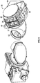
FIG. 5 is an expanded perspective view illustrating the gun sight ofFIG. 4 ; -
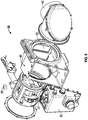
FIG. 6 is an exploded view illustrating the gun sight ofFIG. 5 ; and -
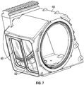
FIG. 7 is an expanded perspective view illustrating a housing for use with the gun sight ofFIG. 5 . - The following detailed description is merely exemplary in nature and is not intended to limit the invention or the application and uses of the invention. Furthermore, there is no intention to be bound by any theory presented in the preceding background or the following detailed description.
- An improved gun sight is disclosed herein that is configured to maintain a line of sight to the target during superelevation of the weapon. The gun sight, or a portion of the gun sight, is configured to rotate with respect to the weapon. The gun sight utilizes a processor, an inclinometer, and a drive mechanism to steady itself at an elevation that aligns the gun sight with a line of sight to a target. The gun sight is mounted to the weapon and will rotate together with the weapon in azimuth and will further rotate together with the weapon elevation during non-superelevating changes in elevation of the weapon. When superelevation is initiated, the processor will use information that is provided by the inclinometer to operate the drive mechanism to rotate the gun sight, or a portion of the gun sight, in a manner that offsets the rotation of the superelevating weapon, thereby allowing the gun sight to maintain a line of sight to the target.
- In one embodiment, the inclinometer may be mounted to the gun sight. When superelevation is initiated, the gun sight will detect its initial angular orientation and the processor will obtain the initial angular orientation from the inclinometer. As the weapon is superelevated, the inclinometer will detect a deviation of the gun sight from the initial angular orientation. When the processor receives information from the inclinometer indicative of the deviation of the gun sight from the initial angular orientation, the processor will instruct the drive mechanism to rotate the gun sight, or a portion of the gun sight, in a manner that offsets the deviation and that maintains the gun sight at the initial angular orientation and, as a result, directs the gun sight's line of sight to the target.
- In another embodiment, the inclinometer may be mounted to the weapon and will detect the angular orientation of the weapon. The weapon will include an additional angle measuring device that is used to provide elevation information to the weapon's fire control system for use in calculating a firing solution. In some embodiements, the additional angle measuring device will measure the angle between the weapon and the gun sight's line of sight (i.e., the superelevation angle). As the weapon is superelevated, changes in the angular orientation of the weapon will be detected by the inclinometer. Changes in the elevation of the weapon will be measured by the angle measuring device. The inclinometer and the angle measuring device will provide information to the processor that indicates that a deviation in the angular orientation of the weapon has occurred and the amount of such deviation. The processor will use this information to control the drive mechanism to rotate the gun sight, or a portion thereof, in a manner that maintains the gun sight at a desired angular orientation that provides the gun sight with a line of sight to the target.
- A greater understanding of the embodiments of the gun sight disclosed herein may be obtained through a review of the illustrations accompanying this application together with a review of the detailed description that follows.
-
FIG. 1 is a block diagram illustrating a non-limiting embodiment of agun sight 10, made in accordance with the teachings of the present disclosure.Gun sight 10 may be adapted for mounting toweapon 12 such thatgun sight 10 rotates in azimuth together withweapon 12 and also rotates in elevation together withweapon 12 at times other than whenweapon 12 is being superelevated. By locking the rotation ofgun sight 10 to that ofweapon 12, the operator is able to both rotate and elevateweapon 12 while looking through a view finder displaying images captured bygun sight 10, allowing the operator to identify and select targets downrange. In some embodiments,weapon 12 andgun sight 10 may be bore sighted such thatweapon 12 andgun sight 10 remain optically locked together in an aligned position, such that the weapon and the gun sight remain pointing at a single down range location.Weapon 12 may be any weapon that utilizes superelevation including, but not limited to mortar launchers, grenade launchers, machine grenade launchers, artillery, rifles, machine guns, and the like. -
Gun sight 10 includes animaging system 14, adrive mechanism 16, aninclinometer 18, and aprocessor 20. In other embodiments,gun sight 10 may include a greater number of components without departing from the teachings of the present disclosure. In some embodiments, each of the components ofgun sight 10 may be enclosed in a single housing, while in other embodiments, only some of the components may be contained within a housing. In still other embodiments, each of the components may be housed separately. In some embodiments, the components ofgun sight 10 may be used exclusively bygun sight 10 while in other embodiments, one or more components may be shared withweapon 12 or some other device. -
Imaging system 14 may comprise any suitable imaging system including, without limitation, a daytime imaging system (e.g., a video camera, television camera), a thermal imaging system, an infrared imaging system, a laser range finder, a radar system, a sonar system, or any other type of system that is configured to perceive and/or detect the presence of an object at a downrange location. In some embodiments,imaging system 14 may include only one type of imaging system while in other embodiments,imaging system 14 may include two or more types of imaging system. By including multiple types of imaging systems, an operator is provided with the flexibility that may be needed to accommodate different or changing battlefield conditions such as nightfall and inclement weather. -
Imaging system 14 is configured to rotate in elevation with respect toweapon 12. Such configuration may be accomplished in any suitable manner. In some embodiments,imaging system 14 may be directly configured to rotate, such as through the use of a central axis extending throughimaging system 14 and/or through rolling engagement between an outer surface ofimaging system 14 and an external supporting surface. In other embodiments,imaging system 14 may be mounted to a carrier or drum that is configured to rotate with respect toweapon 12. In still other embodiments,imaging system 14 may be contained within a housing and the housing may be configured to rotate with respect toweapon 12. In still other embodiments,imaging system 14 may be contained within a housing that remains stationary with respect toweapon 12 and is configured to rotate with respect to the housing. Any other suitable configuration that permitsimaging system 14 to rotate in elevation with respect toweapon 12 may also be employed. -
Imaging system 14 is configured to be operatively coupled with, and to control, adisplay unit 22.Display unit 22 includes adisplay 24 that may be configured to utilize any display technology capable of displaying graphic images.Imaging system 14 is configured to controldisplay unit 22 to display images ondisplay 24 of objects detected by imagingsystem 14. In this manner, potential targets located down range ofgun sight 10 may be presented visually to an operator ofweapon 12.Weapon 12 may include a fire control system that may also be operatively coupled withdisplay unit 22 and that is configured to calculate a firing solution based on the position ofweapon 12. In cases where superelevation ofweapon 12 is necessary, the firing solution will require a change in the elevation angle ofweapon 12. The need to change the elevation angle ofweapon 12 may be communicated to an operator by movement or relocation of one or more reticles on the display. When combined with the images presented byimaging system 14, the reticles allow an operator to target specific objects down range ofweapon 12 and the repositioning of one or more of the reticles ondisplay 24 by the fire control system ofweapon 12 may signal to the operator that superelevation is needed. -
Drive mechanism 16 is associated withimaging system 14.Drive mechanism 16 may comprise any suitable type of drive mechanism including, but not limited to, a servo motor; gear train; feedback device including, but not limited to, an angle encoder.Drive mechanism 16 may be mounted toimaging system 14 or to another structure proximate toimaging system 14.Drive mechanism 16 is configured, mounted, and/or arranged so as to causeimaging system 14 to rotate whendrive mechanism 16 is actuated. In some embodiments,drive mechanism 16 may be configured to causeimaging system 14 to selectively rotate in either a clockwise and a counter-clockwise direction. In some embodiments,gun sight 10 may include more than onedrive mechanism 16 to control rotation ofimaging system 14. -
Inclinometer 18 may comprise any suitable electronic device configured to measure angles of elevation, tilt, slope or depression of an object with respect to a gravitational vector or horizon.Inclinometer 18 may further be configured to output such measured angles to other components that are coupled withinclinometer 18.Inclinometer 18 may be mounted toimaging system 14 or toweapon 12 and, once mounted,inclinometer 18 will detect the angular orientation ofimaging system 14 orinclinometer 18, respectively. As used herein, any reference to measurement of angular orientation byinclinometer 18 refers to the measurement of an elevation angle. The angular orientation detected byinclinometer 18 can be provided to, or retrieved by,processor 20, as discussed below. -
Processor 20 may be any type of computer, controller, micro-controller, circuitry, chipset, computer system, or microprocessor that is configured to perform algorithms, to execute software applications, to execute sub-routines and/or to be loaded with and to execute any other type of computer program.Processor 20 may comprise a single processor or a plurality of processors acting in concert. -
Processor 20 is communicatively coupled to drivemechanism 16 andinclinometer 18. Such coupling may be accomplished through the use of any suitable means of transmission including both wired and wireless connections. In the illustrated embodiment,processor 20 is directly communicatively coupled to eachdrive mechanism 16 and inclinometer, but it should be understood that in other embodiments,processor 20 may be indirectly coupled withdrive mechanism 16 and/orinclinometer 18. For example, such communicative couple may be achieved through the use of a communications bus or via the interposition of intervening components. In still other examples, such coupling may be accomplished through the use of wireless communications such as Bluetooth™ communications or through any other suitable short range radio communications without departing from the teachings of the present disclosure. - Being communicatively coupled provides a pathway for the transmission of commands, instructions, interrogations and other signals between
processor 20, on the one hand, and drivemechanism 16 andinclinometer 18, on the other hand.Drive mechanism 16 andinclinometer 18 may be configured to interface and engage withprocessor 20. For example,drive mechanism 16 may be configured to receive commands fromprocessor 20, either directly or indirectly, and may initiate actuation and/or cease actuation in response to such commands.Inclinometer 18 may be configured to provide angular orientation information toprocessor 20 in response to queries fromprocessor 20 or, alternatively,inclinometer 18 may be configured to continuously or periodically broadcast such information andprocessor 20 may be configured to receive such information. -
Processor 20 is configured to interact with, coordinate, and/or orchestrate the activities ofdrive mechanism 16 andinclinometer 18 for the purpose of maintainingimaging system 14 at a desired (e.g., initial) angle whenweapon 12 is being superelevated. When superelevation is initiated, a signal may be sent toprocessor 20 indicating such initiation. At that time,processor 20 will obtain frominclinometer 18, information that pertains to the angular orientation ofinclinometer 18. Ifinclinometer 18 is mounted toimaging system 14, then the information obtained frominclinometer 18 will be indicative of an initial angular orientation ofimaging system 14 with respect to gravity. Ifinclinometer 18 is mounted toweapon 12, then the information obtained frominclinometer 18 will be indicative of a current angular orientation ofweapon 12 with respect to gravity.Processor 20 will utilize the information provided byinclinometer 18 to determine when and how to actuatedrive mechanism 16 in order to maintainimaging system 14 at an angle that permitsimaging system 14 to a maintain line of sight with a desired target. Prior to any change in elevation ofweapon 12,processor 20 will not issue any commands to drivemechanism 16 and the angular orientation ofimaging system 14 will remain unchanged. - When the elevation angle of
weapon 12 begins to change during superelevation,processor 20 will receive updated information frominclinometer 18 that is reflective of a change in the angular orientation of eitherimaging system 14 orweapon 12.Processor 20 will utilize this updated information to provide instructions to drivemechanism 16 to thereby causedrive mechanism 16 to rotateimaging system 14 in a manner that offsets the change in elevation ofweapon 12, the goal being to maintain a line of sight betweenimaging system 14 and the target. Further changes in the elevation angle ofweapon 12 will cause further changes in the angular orientation ofinclinometer 18, which will be obtained byprocessor 20 and used to provide further instructions to drivemechanism 16 to adjust the angular orientation ofimaging system 14. This process will continue in an iterative manner throughout the period whenweapon 12 is being superelevated, causing the angular orientation ofimaging system 14 to be repeatedly adjusted in a manner that offsets the rotation ofweapon 12. This ensures thatimaging system 14 maintains the line of sight to the target. This, in turn, allows the image of the desired target to remain ondisplay 24 throughout the entire period of superelevation ofweapon 12. -
FIG. 2 is a block diagram illustrating another non-limiting embodiment ofgun sight 10 ofFIG. 1 . Ingun sight 26,inclinometer 18 is associated withimaging system 14. In some embodiments,inclinometer 18 may be mounted directly toimaging system 14. In other embodiments,inclinometer 18 may be mounted indirectly toimaging system 14. For example,inclinometer 18 may be mounted to a structure that is connected toimaging system 14, one that will rotate together withimaging system 14. Mounted in this manner,inclinometer 18 will be able to detect the angular orientation ofimaging system 14. - In
gun sight 26,processor 20 is configured to stabilizeimaging system 14 during superelevation ofweapon 12 by controllingdrive mechanism 16 to maintain an initial angular orientation ofimaging system 14.Processor 20 may be configured to receive input from an operator or fromweapon 12 that contains information that is indicative of the initiation of superelevation ofweapon 12. For example, to initiate superelevation ofweapon 12, an operator may actuate a switch onweapon 12. This actuation may send a signal toprocessor 20 indicating that superelevation has commenced. - In response to receiving the information that superelevation has commenced,
processor 20 will obtain the current angular orientation ofimaging system 14 frominclinometer 18 and store this angle as the initial angular orientation ofimaging system 14. Becauseimaging system 14 is mounted toweapon 12, asweapon 12 is superelevated, the angular orientation ofimaging system 14 will begin to change. As the angular orientation ofimaging system 14 begins to change,inclinometer 18 will report the new angular orientation ofimaging system 14 toprocessor 20. Whenprocessor 20 detects that the new angular orientation ofimaging system 14 differs from the initial angular orientation ofimaging system 14,processor 20 will send instructions to drivemechanism 16 to rotateimaging system 14 in a manner that counteracts the rotation ofweapon 12 and that restoresprocessor 20 to (or maintainsprocessor 20 at) its initial angular orientation. This process of correcting any deviation detected in the angular orientation ofimaging system 14 will continue in an iterative manner throughout the period whenweapon 12 is being superelevated. Onceweapon 12 has reached the desired elevation angle, the operator ofweapon 12 orweapon 12 itself or the fire control system associated withweapon 12 will provide a second input toprocessor 20 indicating that superelevation has been completed. At this point,processor 20 may cease providing instructions to drivemechanism 16 andimaging system 14 will be permitted to, once again, rotate together withweapon 12. - By implementing the above described protocol, any change in angular orientation of
imaging system 14 that would have otherwise resulted from the superelevation ofweapon 12 is offset by a series of counter-rotations ofimaging system 14 or, depending upon calibrations and sensitivities of equipment, by a smooth, continuous counter-rotation ofimaging system 14. This counter-rotation allowsimaging system 14 to maintain its line of sight to the desired target throughout the period whenweapon 12 is being superelevated. So long asimaging system 14 maintains its line of sight to the desired target, the image of the desired target that is captured by imagingsystem 14 will remain ondisplay 24. -
FIG. 3 is a block diagram illustrating another non-limiting embodiment ofgun sight 10 ofFIG. 1 . Ingun sight 28,inclinometer 18 is associated withweapon 12. In some embodiments,inclinometer 18 may be mounted directly toweapon 12 while in other embodiments,inclinometer 18 may be indirectly mounted toweapon 12 such as through an intervening structure or other component that is mounted toweapon 12. Mounted in this manner,inclinometer 18 will be able to detect the angular orientation ofweapon 12. - In
FIG. 3 ,weapon 12 includes anangle measuring device 30 that is configured to measure changes in the angle between theweapon 12 andimaging system 14.Angle measuring device 30 may be any device suitable for measuring change in angular orientation between two components including, but not limited to, an encoder and a resolver. In some embodiments, an inclinometer may be utilized asangle measuring device 30. -
Angle measuring device 30 is configured to report measured changes in angular orientation ofweapon 12 relative to gunsight imaging system 14 in elevation axis to a fire control system associated withweapon 12. The fire control system may utilize such measured changes in angular orientation to determine firing solutions and also to control the placement of a reticle ondisplay 24. -
Angle measuring device 30 may also configured to measure the angular orientation of the gun sight (gun sight 28) with respect toweapon 12. In other embodiments,weapon 12 may include two angle measuring devices, one to measure the change in angular orientation ofweapon 12 and the other to measure the angular orientation ofgun sight 28 with respect toweapon 12. - In
gun sight 28,processor 20 is configured to receive information frominclinometer 18 indicative of the angular orientation ofweapon 12.Processor 20 is further configured to receive information fromangle measuring device 30 indicative of the then current angular orientation or change in angular orientation ofweapon 12.Processor 20 is further configured to receive input from either an operator or fromweapon 12 containing information that is indicative of the initiation of superelevation ofweapon 12. For example, to initiate superelevation ofweapon 12, the operator may actuate a switch onweapon 12. This actuation may send a signal toprocessor 20 indicating that superelevation has commenced. At the start of superelevation,imaging system 14 is oriented at an angle that provides a line of sight to the desired target. This angle will be referred to herein as the desired angular orientation ofimaging system 14.Processor 20 will maintainimaging system 14 at the desired angular orientation throughout the superelevation ofweapon 12. - In response to receiving the information that superelevation has commenced,
processor 20 will obtain the current angular orientation ofweapon 12 frominclinometer 18 and the change in angular orientation ofweapon 12 which, at the outset of superelevation, will be zero. Asweapon 12 is superelevated, the angular orientation ofweapon 12 will begin to change. The change in angular orientation will be detected byinclinometer 18 and reported toprocessor 20. Additionally, asweapon 12 is superelevated,angle measuring device 30 will begin to measure or otherwise detect changes in the angular orientation ofweapon 12 and will report such changes toprocessor 20. -
Processor 20 is configured to utilize the information provided byinclinometer 18 and byangle measuring device 30 to controldrive mechanism 16 in a manner that maintainsimaging system 14 at the desired angular orientation. For example,processor 20 will send instructions to drivemechanism 16 that will controldrive mechanism 16 to rotateimaging system 14 in a direction and by an amount that offsets the change in angular orientation measured byangle measuring device 30. Asweapon 12 continues to superelevate, new angular orientations will repeatedly be detected byinclinometer 18 and new measured changes in elevation will repeatedly be measured byangle measuring device 30. As this new information is received byprocessor 20,processor 20 will repeatedly send additional commands to drivemechanism 16 that will causedrive mechanism 16 to rotateimaging system 14 in a manner that offsets the changes in angular orientation that would otherwise be brought about by the superelevation ofweapon 12. In this iterative manner,imaging system 14 will be maintained at the desired angular orientation during the superelevation ofweapon 12. - Once
weapon 12 has reached the desired elevation angle, the operator ofweapon 12 orweapon 12 itself or the fire control system associated withweapon 12 may provide a second input toprocessor 20 indicating that superelevation has been completed. At this point,processor 20 will cease providing instructions to drivemechanism 16 that causedrive mechanism 16 to rotateimaging system 14 andimaging system 14 will, once again, be permitted to rotate together withweapon 12 in both azimuth and elevation. - By implementing the above described protocol, any change in angular orientation of
imaging system 14 that would have otherwise resulted from the superelevation ofweapon 12 may be offset by a series of counter-rotations ofimaging system 14 or, depending upon the calibration and sensitivities of equipment, by a smooth, continuous rotation ofimaging system 14. These counter-rotations allowimaging system 14 to maintain its line of sight to the desired target throughout the period whenweapon 12 is being superelevated. So long asimaging system 14 maintains its line of sight to the desired target, the image of the desired target that is captured by imagingsystem 14 will remain ondisplay 24. -
FIG. 4 is a perspective view of aweapon system 32 including amachine grenade launcher 34 and agun sight 36.Machine grenade launcher 34 is configured for superelevation andgun sight 36 has been configured to maintain a line of sight with a target asmachine grenade launcher 34 is being superelevated. Adisplay unit 35 is illustrated extending frommachine grenade launcher 34 and is used by the operator to scan the down field area for targets. -
FIG. 5 is an expanded perspective view ofgun sight 36.Gun sight 36 includes animaging system 37 including three discrete imaging sub-systems; alaser range finder 38, adaylight imaging sub-system 40, and athermal imaging sub-system 42. With continuing reference toFIG. 4 ,underside 44 ofgun sight 36 is configured to be mounted tomachine grenade launcher 34 via mount 46 (seeFIG. 4 ). Ahousing 48 surroundsimaging system 37 to protect it from the elements.Imaging system 37 is configured to rotate with respect tohousing 48 andhousing 48 is configured to rotate together withmachine grenade launcher 34 when machine grenade launcher is superelevated.Thermal imaging sub-system 42 is physically connected with the remainder ofimaging system 37, but extends outside ofhousing 48. Because of its physical connection to the remainder ofimaging system 37,thermal imaging sub-system 42 also rotates with respect tohousing 48 during superelevation ofmachine grenade launcher 34.Circuit card assembly 50 contains various circuit cards and/or controllers and/or processors which may be configured to control the angular orientation ofimaging system 37 in the manner discussed above withrespect processor 20 ofFIGS. 2 and3 . -
FIG. 6 is an exploded view ofgun sight 36.Housing 48 includes abore 52 extending laterally throughhousing 48.Imaging system 37 is mounted within adrum 54.Drum 54 is generally cylindrical in configuration and has a circular cross section.Bore 52 is configured to receivedrum 54 anddrum 54 is configured to rotate with respect tohousing 48 while received withinbore 52. - An
inclinometer 56 is also illustrated inFIG. 6 . Depending upon howcircuit card assembly 50 is programmed (i.e., in accordance with the protocol discussed above with respect to eitherFIG. 2 orFIG. 3 ),inclinometer 56 may be assembled to drum 54, toimaging system 37, tohousing 48, tocircuit card assembly 50, or tomachine grenade launcher 34. In embodiments wherecircuit card assembly 50 is programmed to follow the protocol discussed above in conjunction withFIG. 2 , theninclinometer 56 would be mounted either to drum 54 or toimaging system 37. In embodiments wherecircuit card assembly 50 is programmed to follow the protocol discussed above in conjunction withFIG. 3 , theninclinometer 56 will be mounted tohousing 48, tocircuit card assembly 50, or onmachine grenade launcher 34. - A drive mechanism 58 is also illustrated in
FIG. 6 . Drive mechanism 58 is configured to mount tohousing 48 and to engagedrum 54. When drive mechanism 58 is actuated bycircuit card assembly 50, it will causedrum 54 to rotate either clockwise or counter-clockwise, as needed, to maintainimaging system 37 in a steady angular orientation asmachine grenade launcher 34 is superelevated. -
FIG. 7 is an expanded perspective view ofhousing 48.Housing 48 includeswindows FIG. 5 ,windows laser range finder 38 anddaylight imaging sub-system 40 to receive images of the down range area without obstruction, while still permitting the use of dry air or dry nitrogen inside ofhousing 48 to inhibit fogging of the optical elements comprising imaging system components..
Claims (15)
- A gun sight (10, 26, 28, 36) for use with a weapon (12, 32), the gun sight comprising:an imaging system (14) configured for rotation in elevation;a drive mechanism (16) associated with the imaging system (14) and configured to rotate the imaging system (14);an inclinometer (18) associated with one of the weapon and the imaging system; anda processor (20) communicatively coupled with the drive mechanism (16) and the inclinometer (18) and configured to control the drive mechanism (16) to rotate the imaging system (14) in an iterative manner throughout the period when the weapon (12, 32) is being superelevated such it exceeds the field of view of the imaging system (14), causing the angular orientation of the imaging system (14) to be repeatedly adjusted in a manner that offsets rotation of the weapon to cause the imaging system to maintain an initial angular orientation based, at least in part, on information provided by the inclinometer.
- The gun sight (10, 26, 28, 36) of claim 1, wherein the information provided by the inclinometer (18) is indicative of a change in angular orientation of the inclinometer.
- The gun sight (10, 26, 28, 36) of claim 1, wherein the inclinometer (18) is associated with the imaging system (14) and wherein the processor (20) is configured to control the drive mechanism (16) to rotate the imaging system when the inclinometer detects a change in an angular orientation of the imaging system.
- The gun sight (10, 26, 28, 36) of claim 1, wherein the inclinometer (18) is associated with the weapon and wherein the processor (20) is configured to control the drive mechanism (16) to rotate the imaging system when the inclinometer detects a change in an angular orientation of the weapon.
- The gun sight (10, 26, 28, 36) of claim 1:wherein the imaging system (14) is adapted to be operatively coupled to a display unit (22) having a display (24), the imaging system configured to control the display unit to depict an image of a scene that includes a target;wherein the inclinometer (18) is associated with the imaging system and configured to detect both an angular orientation of the imaging system and a change in the angular orientation of the imaging system; andwherein the processor (20) is configured to control the drive mechanism (16) to rotate the imaging system (14) based, at least in part, on information provided by the inclinometer when the inclinometer detects the change in the angular orientation of the imaging system during superelevation of the weapon.
- The gun sight (10, 26, 28, 36) of claim 5, wherein the processor (20) is configured to control the drive mechanism (16) to rotate the imaging system to cause the target to continuously remain stabilized on the display during superelevation of the weapon.
- The gun sight (10, 26, 28, 36) of claim 5, wherein the processor (20) is configured to obtain the initial angular orientation of the imaging system (14) from the inclinometer (18) when superelevation of the weapon is initiated.
- The gun sight (10, 26, 28, 36) of claim 5, further comprising a housing (48), wherein the imaging system is enclosed within the housing, wherein the housing is configured to rotate together with the weapon during superelevation, and wherein the imaging system is configured to rotate with respect to the housing.
- The gun sight (10, 26, 28, 36) of claim 8, further comprising a drum (54), wherein the imaging system is mounted to the drum and wherein the drum is rotatably mounted to the housing (48); and
wherein the drive mechanism is configured to engage the drum and rotate the drum in relation to the housing. - The gun sight (10, 26, 28, 36) of claim 5, wherein the imaging system comprises a daylight imaging system (40) and a laser range finder (38); and
wherein the imaging system further comprises a thermal imaging system (42). - The gun sight (10, 26, 28, 36) of claim 1, comprising:an angle measuring device (30) configured to measure changes in the angle between the weapon (12) and the imaging system (14):wherein the imaging system is adapted to be operatively coupled to a display unit having a display, the imaging system configured to control the display unit to display an image of a scene that includes a target;wherein the inclinometer is adapted for mounting to the weapon and configured to detect a current angular orientation of the weapon; andwherein the processor is adapted for communicative coupling with the angle measuring device (30), the processor configured to obtain the current angular orientation of the weapon during superelevation from the inclinometer and to obtain the change in the angular orientation of the weapon during superelevation from the angle measuring device, the processor further configured to control the drive mechanism to maintain a desired angular orientation of the imaging system based, at least in part, on information provided by the inclinometer when the inclinometer detects the change in the angular orientation of the weapon while the weapon is superelevated.
- The gun sight (10, 26, 28, 36) of claim 11, wherein the processor (20) is configured to control the drive mechanism (16) to rotate the imaging system to cause the target to continuously remain stabilized on the display during superelevation of the weapon.
- The gun sight (10, 26, 28, 36) of claim 11, wherein the processor (20) is configured to calculate the desired angular orientation of the imaging system (14) by subtracting the change in the angular orientation of the weapon from the current angular orientation of the weapon.
- The gun sight (10, 26, 28, 36) of claim 11, further comprising a housing (48), wherein the imaging system (14) is enclosed within the housing, wherein the housing is configured to rotate together with the weapon during superelevation, and wherein the imaging system is configured to rotate with respect to the housing.
- The gun sight (10, 26, 28, 36) of claim 14, further comprising a drum (54), wherein the imaging system (14) is mounted to the drum and wherein the drum is rotatably mounted to the housing; and
wherein the drive mechanism is configured to engage the drum.
Applications Claiming Priority (2)
| Application Number | Priority Date | Filing Date | Title |
|---|---|---|---|
| US201161565296P | 2011-11-30 | 2011-11-30 | |
| PCT/US2012/067084 WO2013126110A2 (en) | 2011-11-30 | 2012-11-29 | Gun sight for use with superelevating weapon |
Publications (3)
| Publication Number | Publication Date |
|---|---|
| EP2800942A2 EP2800942A2 (en) | 2014-11-12 |
| EP2800942A4 EP2800942A4 (en) | 2015-07-15 |
| EP2800942B1 true EP2800942B1 (en) | 2018-05-09 |
Family
ID=48465612
Family Applications (1)
| Application Number | Title | Priority Date | Filing Date |
|---|---|---|---|
| EP12869494.0A Active EP2800942B1 (en) | 2011-11-30 | 2012-11-29 | Gun sight for use with superelevating weapon |
Country Status (7)
| Country | Link |
|---|---|
| US (2) | US9052158B2 (en) |
| EP (1) | EP2800942B1 (en) |
| AU (1) | AU2012370428B2 (en) |
| ES (1) | ES2685344T3 (en) |
| IL (1) | IL232891B (en) |
| SG (1) | SG11201402717VA (en) |
| WO (2) | WO2013126110A2 (en) |
Families Citing this family (15)
| Publication number | Priority date | Publication date | Assignee | Title |
|---|---|---|---|---|
| US8978539B2 (en) * | 2012-02-09 | 2015-03-17 | Wilcox Industries Corp. | Weapon video display system employing smartphone or other portable computing device |
| US9404713B2 (en) | 2013-03-15 | 2016-08-02 | General Dynamics Ordnance And Tactical Systems, Inc. | Gun sight for use with superelevating weapon |
| US9335109B2 (en) * | 2013-08-16 | 2016-05-10 | Maiquel Bensayan | Realtime memorialization firearm attachment |
| DE102013014619A1 (en) * | 2013-09-04 | 2015-03-05 | Rheinmetall Soldier Electronics Gmbh | Targeting means for handguns and small arms with the target agent as well as adjustment of the target agent |
| TWI524211B (en) * | 2013-09-11 | 2016-03-01 | 萬國商業機器公司 | Electronic apparatus and display angle adjustment method therewith |
| US9476676B1 (en) | 2013-09-15 | 2016-10-25 | Knight Vision LLLP | Weapon-sight system with wireless target acquisition |
| GB2523911B (en) * | 2014-03-03 | 2021-04-07 | Wilcox Ind Corp | Modular sighting assembly and method |
| DE102014114036A1 (en) * | 2014-09-26 | 2016-03-24 | Cassidian Optronics Gmbh | Straightening and guiding device and method for supporting a gunner of a weapon system |
| DE102014019199A1 (en) | 2014-12-19 | 2016-06-23 | Diehl Bgt Defence Gmbh & Co. Kg | automatic weapon |
| US10488155B2 (en) * | 2015-01-23 | 2019-11-26 | Raytheon Company | Method and apparatus for electro-mechanical super-elevation |
| CN105300183B (en) * | 2015-10-30 | 2017-08-01 | 北京艾克利特光电科技有限公司 | A sight assembly capable of automatic tracking and aiming and a shooting method for automatic tracking and aiming |
| US10378858B2 (en) * | 2016-01-21 | 2019-08-13 | Kai W. Gull | Systems, devices and methods for visualizing a target |
| US10458754B2 (en) * | 2017-05-15 | 2019-10-29 | T-Worx Holdings, LLC | System and method for networking firearm-mounted devices |
| US10641583B2 (en) * | 2017-07-20 | 2020-05-05 | Trent Zimmer | Firearm accessory electrical distribution system |
| US11372408B1 (en) * | 2018-08-08 | 2022-06-28 | Amazon Technologies, Inc. | Dynamic trajectory-based orientation of autonomous mobile device component |
Family Cites Families (18)
| Publication number | Priority date | Publication date | Assignee | Title |
|---|---|---|---|---|
| US2538821A (en) * | 1945-12-19 | 1951-01-23 | Wheeler Phillip Rood | Electrical gunsight superelevation and roll correcting device |
| DE1946972C3 (en) * | 1968-09-25 | 1978-08-31 | Karl Ing. Wien Vockenhuber | Sighting device, in particular a telescopic sight |
| SE331245B (en) | 1969-01-03 | 1970-12-14 | Bofors Ab | |
| US4760770A (en) | 1982-11-17 | 1988-08-02 | Barr & Stroud Limited | Fire control systems |
| SE459209B (en) | 1985-08-19 | 1989-06-12 | Saab Instr Ab | LUFTVAERNSSIKTE |
| US5171933A (en) | 1991-12-20 | 1992-12-15 | Imo Industries, Inc. | Disturbed-gun aiming system |
| US5456157A (en) | 1992-12-02 | 1995-10-10 | Computing Devices Canada Ltd. | Weapon aiming system |
| CA2245406C (en) | 1998-08-24 | 2006-12-05 | James Hugh Lougheed | Aiming system for weapon capable of superelevation |
| US6349477B1 (en) * | 1999-11-01 | 2002-02-26 | The Regents Of The University Of California | Self adjusting inclinometer |
| SE519151E5 (en) | 2001-11-19 | 2013-07-30 | Bae Systems Bofors Ab | Weapon sight with sight sensors intended for vehicles, vessels or equivalent |
| JP3602519B2 (en) | 2002-07-12 | 2004-12-15 | コナミ株式会社 | Video game apparatus, image processing method, and program |
| US6769347B1 (en) | 2002-11-26 | 2004-08-03 | Recon/Optical, Inc. | Dual elevation weapon station and method of use |
| DE102005007910A1 (en) * | 2005-02-08 | 2006-08-10 | Carl Zeiss Optronics Gmbh | Firearm for long flight duration projectiles has fire guidance system with target data acquisition and adjusters for sight tube on weapon |
| US7614805B2 (en) | 2006-11-07 | 2009-11-10 | Joseph Showalter | Image capture device mounting assembly for firearm |
| US20090040308A1 (en) | 2007-01-15 | 2009-02-12 | Igor Temovskiy | Image orientation correction method and system |
| SE534612C2 (en) | 2009-07-08 | 2011-10-25 | Gs Dev Ab | Fire control systems |
| DE102009033567A1 (en) | 2009-07-16 | 2011-01-27 | Rheinmetall Soldier Electronics Gmbh | Fire control device for a handgun |
| KR101237129B1 (en) | 2010-05-19 | 2013-02-25 | 정인 | sighting apparatus for remote-control shooting system and sight alignment method using the same |
-
2012
- 2012-11-29 US US13/688,779 patent/US9052158B2/en active Active
- 2012-11-29 ES ES12869494.0T patent/ES2685344T3/en active Active
- 2012-11-29 WO PCT/US2012/067084 patent/WO2013126110A2/en not_active Ceased
- 2012-11-29 AU AU2012370428A patent/AU2012370428B2/en active Active
- 2012-11-29 WO PCT/US2012/067088 patent/WO2013126112A2/en not_active Ceased
- 2012-11-29 SG SG11201402717VA patent/SG11201402717VA/en unknown
- 2012-11-29 EP EP12869494.0A patent/EP2800942B1/en active Active
- 2012-11-29 US US13/688,946 patent/US9057581B2/en active Active
-
2014
- 2014-05-29 IL IL232891A patent/IL232891B/en active IP Right Grant
Non-Patent Citations (1)
| Title |
|---|
| None * |
Also Published As
| Publication number | Publication date |
|---|---|
| EP2800942A4 (en) | 2015-07-15 |
| WO2013126112A3 (en) | 2013-10-17 |
| WO2013126112A2 (en) | 2013-08-29 |
| US9052158B2 (en) | 2015-06-09 |
| IL232891A0 (en) | 2014-07-31 |
| US20140103112A1 (en) | 2014-04-17 |
| WO2013126110A3 (en) | 2013-10-17 |
| IL232891B (en) | 2018-02-28 |
| US9057581B2 (en) | 2015-06-16 |
| ES2685344T3 (en) | 2018-10-08 |
| SG11201402717VA (en) | 2014-09-26 |
| EP2800942A2 (en) | 2014-11-12 |
| AU2012370428B2 (en) | 2016-06-16 |
| AU2012370428A1 (en) | 2014-06-19 |
| US20130133510A1 (en) | 2013-05-30 |
| WO2013126110A2 (en) | 2013-08-29 |
Similar Documents
| Publication | Publication Date | Title |
|---|---|---|
| AU2012370428B2 (en) | Gun sight for use with superelevating weapon | |
| US6769347B1 (en) | Dual elevation weapon station and method of use | |
| US7089845B2 (en) | Method and device for aiming a weapon barrel and use of the device | |
| US4885977A (en) | Stabilized line-of-sight aiming system for use with fire control systems | |
| EP4325162B1 (en) | Method of aiming a grenade launcher | |
| US9243931B2 (en) | AZ/EL gimbal housing characterization | |
| US20060272194A1 (en) | Firearm for low velocity projectiles | |
| EP2972055B1 (en) | Gun sight for use with superelevating weapon | |
| US20170227328A1 (en) | Fire-control device for a small arm and small arm | |
| CN212620377U (en) | Mortar quick shooting device | |
| US20250257982A1 (en) | Dual trigger weapon control system with integrated manual and assisted targeting | |
| RU2555643C1 (en) | Method of automatic armaments homing at moving target | |
| KR101375181B1 (en) | Armament system | |
| RU2485430C1 (en) | Method of firing by guided missile with laser semi-active homing head |
Legal Events
| Date | Code | Title | Description |
|---|---|---|---|
| PUAI | Public reference made under article 153(3) epc to a published international application that has entered the european phase |
Free format text: ORIGINAL CODE: 0009012 |
|
| 17P | Request for examination filed |
Effective date: 20140630 |
|
| AK | Designated contracting states |
Kind code of ref document: A2 Designated state(s): AL AT BE BG CH CY CZ DE DK EE ES FI FR GB GR HR HU IE IS IT LI LT LU LV MC MK MT NL NO PL PT RO RS SE SI SK SM TR |
|
| RAP1 | Party data changed (applicant data changed or rights of an application transferred) |
Owner name: GENERAL DYNAMICS-OTS, INC. |
|
| RIN1 | Information on inventor provided before grant (corrected) |
Inventor name: PIAZZA, JONATHAN Inventor name: PEPPER, CRAIG N. Inventor name: KRYLOV, VLADIMIR G. Inventor name: FLETCHER, JOHN GROVER III Inventor name: BLOOMHARDT, THEODORE E |
|
| RAP1 | Party data changed (applicant data changed or rights of an application transferred) |
Owner name: GENERAL DYNAMICS-OTS, INC. |
|
| DAX | Request for extension of the european patent (deleted) | ||
| A4 | Supplementary search report drawn up and despatched |
Effective date: 20150612 |
|
| RIC1 | Information provided on ipc code assigned before grant |
Ipc: F41G 1/473 20060101ALI20150608BHEP Ipc: F41G 3/16 20060101ALI20150608BHEP Ipc: F41G 1/50 20060101ALI20150608BHEP Ipc: F41G 3/06 20060101AFI20150608BHEP |
|
| STAA | Information on the status of an ep patent application or granted ep patent |
Free format text: STATUS: EXAMINATION IS IN PROGRESS |
|
| 17Q | First examination report despatched |
Effective date: 20170126 |
|
| GRAP | Despatch of communication of intention to grant a patent |
Free format text: ORIGINAL CODE: EPIDOSNIGR1 |
|
| STAA | Information on the status of an ep patent application or granted ep patent |
Free format text: STATUS: GRANT OF PATENT IS INTENDED |
|
| INTG | Intention to grant announced |
Effective date: 20171128 |
|
| GRAS | Grant fee paid |
Free format text: ORIGINAL CODE: EPIDOSNIGR3 |
|
| GRAA | (expected) grant |
Free format text: ORIGINAL CODE: 0009210 |
|
| STAA | Information on the status of an ep patent application or granted ep patent |
Free format text: STATUS: THE PATENT HAS BEEN GRANTED |
|
| AK | Designated contracting states |
Kind code of ref document: B1 Designated state(s): AL AT BE BG CH CY CZ DE DK EE ES FI FR GB GR HR HU IE IS IT LI LT LU LV MC MK MT NL NO PL PT RO RS SE SI SK SM TR |
|
| REG | Reference to a national code |
Ref country code: GB Ref legal event code: FG4D |
|
| REG | Reference to a national code |
Ref country code: CH Ref legal event code: EP Ref country code: AT Ref legal event code: REF Ref document number: 997974 Country of ref document: AT Kind code of ref document: T Effective date: 20180515 |
|
| REG | Reference to a national code |
Ref country code: IE Ref legal event code: FG4D |
|
| REG | Reference to a national code |
Ref country code: DE Ref legal event code: R096 Ref document number: 602012046277 Country of ref document: DE |
|
| REG | Reference to a national code |
Ref country code: SE Ref legal event code: TRGR |
|
| REG | Reference to a national code |
Ref country code: NL Ref legal event code: MP Effective date: 20180509 |
|
| REG | Reference to a national code |
Ref country code: LT Ref legal event code: MG4D |
|
| REG | Reference to a national code |
Ref country code: ES Ref legal event code: FG2A Ref document number: 2685344 Country of ref document: ES Kind code of ref document: T3 Effective date: 20181008 |
|
| REG | Reference to a national code |
Ref country code: NO Ref legal event code: T2 Effective date: 20180509 |
|
| PG25 | Lapsed in a contracting state [announced via postgrant information from national office to epo] |
Ref country code: BG Free format text: LAPSE BECAUSE OF FAILURE TO SUBMIT A TRANSLATION OF THE DESCRIPTION OR TO PAY THE FEE WITHIN THE PRESCRIBED TIME-LIMIT Effective date: 20180809 Ref country code: FI Free format text: LAPSE BECAUSE OF FAILURE TO SUBMIT A TRANSLATION OF THE DESCRIPTION OR TO PAY THE FEE WITHIN THE PRESCRIBED TIME-LIMIT Effective date: 20180509 Ref country code: LT Free format text: LAPSE BECAUSE OF FAILURE TO SUBMIT A TRANSLATION OF THE DESCRIPTION OR TO PAY THE FEE WITHIN THE PRESCRIBED TIME-LIMIT Effective date: 20180509 |
|
| PG25 | Lapsed in a contracting state [announced via postgrant information from national office to epo] |
Ref country code: GR Free format text: LAPSE BECAUSE OF FAILURE TO SUBMIT A TRANSLATION OF THE DESCRIPTION OR TO PAY THE FEE WITHIN THE PRESCRIBED TIME-LIMIT Effective date: 20180810 Ref country code: LV Free format text: LAPSE BECAUSE OF FAILURE TO SUBMIT A TRANSLATION OF THE DESCRIPTION OR TO PAY THE FEE WITHIN THE PRESCRIBED TIME-LIMIT Effective date: 20180509 Ref country code: HR Free format text: LAPSE BECAUSE OF FAILURE TO SUBMIT A TRANSLATION OF THE DESCRIPTION OR TO PAY THE FEE WITHIN THE PRESCRIBED TIME-LIMIT Effective date: 20180509 Ref country code: NL Free format text: LAPSE BECAUSE OF FAILURE TO SUBMIT A TRANSLATION OF THE DESCRIPTION OR TO PAY THE FEE WITHIN THE PRESCRIBED TIME-LIMIT Effective date: 20180509 Ref country code: RS Free format text: LAPSE BECAUSE OF FAILURE TO SUBMIT A TRANSLATION OF THE DESCRIPTION OR TO PAY THE FEE WITHIN THE PRESCRIBED TIME-LIMIT Effective date: 20180509 |
|
| REG | Reference to a national code |
Ref country code: AT Ref legal event code: MK05 Ref document number: 997974 Country of ref document: AT Kind code of ref document: T Effective date: 20180509 |
|
| PG25 | Lapsed in a contracting state [announced via postgrant information from national office to epo] |
Ref country code: AT Free format text: LAPSE BECAUSE OF FAILURE TO SUBMIT A TRANSLATION OF THE DESCRIPTION OR TO PAY THE FEE WITHIN THE PRESCRIBED TIME-LIMIT Effective date: 20180509 Ref country code: PL Free format text: LAPSE BECAUSE OF FAILURE TO SUBMIT A TRANSLATION OF THE DESCRIPTION OR TO PAY THE FEE WITHIN THE PRESCRIBED TIME-LIMIT Effective date: 20180509 Ref country code: DK Free format text: LAPSE BECAUSE OF FAILURE TO SUBMIT A TRANSLATION OF THE DESCRIPTION OR TO PAY THE FEE WITHIN THE PRESCRIBED TIME-LIMIT Effective date: 20180509 Ref country code: EE Free format text: LAPSE BECAUSE OF FAILURE TO SUBMIT A TRANSLATION OF THE DESCRIPTION OR TO PAY THE FEE WITHIN THE PRESCRIBED TIME-LIMIT Effective date: 20180509 Ref country code: RO Free format text: LAPSE BECAUSE OF FAILURE TO SUBMIT A TRANSLATION OF THE DESCRIPTION OR TO PAY THE FEE WITHIN THE PRESCRIBED TIME-LIMIT Effective date: 20180509 Ref country code: CZ Free format text: LAPSE BECAUSE OF FAILURE TO SUBMIT A TRANSLATION OF THE DESCRIPTION OR TO PAY THE FEE WITHIN THE PRESCRIBED TIME-LIMIT Effective date: 20180509 Ref country code: SK Free format text: LAPSE BECAUSE OF FAILURE TO SUBMIT A TRANSLATION OF THE DESCRIPTION OR TO PAY THE FEE WITHIN THE PRESCRIBED TIME-LIMIT Effective date: 20180509 |
|
| REG | Reference to a national code |
Ref country code: DE Ref legal event code: R097 Ref document number: 602012046277 Country of ref document: DE |
|
| PG25 | Lapsed in a contracting state [announced via postgrant information from national office to epo] |
Ref country code: SM Free format text: LAPSE BECAUSE OF FAILURE TO SUBMIT A TRANSLATION OF THE DESCRIPTION OR TO PAY THE FEE WITHIN THE PRESCRIBED TIME-LIMIT Effective date: 20180509 Ref country code: IT Free format text: LAPSE BECAUSE OF FAILURE TO SUBMIT A TRANSLATION OF THE DESCRIPTION OR TO PAY THE FEE WITHIN THE PRESCRIBED TIME-LIMIT Effective date: 20180509 |
|
| PLBE | No opposition filed within time limit |
Free format text: ORIGINAL CODE: 0009261 |
|
| STAA | Information on the status of an ep patent application or granted ep patent |
Free format text: STATUS: NO OPPOSITION FILED WITHIN TIME LIMIT |
|
| 26N | No opposition filed |
Effective date: 20190212 |
|
| PG25 | Lapsed in a contracting state [announced via postgrant information from national office to epo] |
Ref country code: SI Free format text: LAPSE BECAUSE OF FAILURE TO SUBMIT A TRANSLATION OF THE DESCRIPTION OR TO PAY THE FEE WITHIN THE PRESCRIBED TIME-LIMIT Effective date: 20180509 |
|
| REG | Reference to a national code |
Ref country code: CH Ref legal event code: PL |
|
| PG25 | Lapsed in a contracting state [announced via postgrant information from national office to epo] |
Ref country code: MC Free format text: LAPSE BECAUSE OF FAILURE TO SUBMIT A TRANSLATION OF THE DESCRIPTION OR TO PAY THE FEE WITHIN THE PRESCRIBED TIME-LIMIT Effective date: 20180509 Ref country code: LU Free format text: LAPSE BECAUSE OF NON-PAYMENT OF DUE FEES Effective date: 20181129 |
|
| REG | Reference to a national code |
Ref country code: BE Ref legal event code: MM Effective date: 20181130 |
|
| REG | Reference to a national code |
Ref country code: IE Ref legal event code: MM4A |
|
| PG25 | Lapsed in a contracting state [announced via postgrant information from national office to epo] |
Ref country code: CH Free format text: LAPSE BECAUSE OF NON-PAYMENT OF DUE FEES Effective date: 20181130 Ref country code: LI Free format text: LAPSE BECAUSE OF NON-PAYMENT OF DUE FEES Effective date: 20181130 |
|
| PG25 | Lapsed in a contracting state [announced via postgrant information from national office to epo] |
Ref country code: FR Free format text: LAPSE BECAUSE OF NON-PAYMENT OF DUE FEES Effective date: 20181130 Ref country code: IE Free format text: LAPSE BECAUSE OF NON-PAYMENT OF DUE FEES Effective date: 20181129 |
|
| PG25 | Lapsed in a contracting state [announced via postgrant information from national office to epo] |
Ref country code: AL Free format text: LAPSE BECAUSE OF FAILURE TO SUBMIT A TRANSLATION OF THE DESCRIPTION OR TO PAY THE FEE WITHIN THE PRESCRIBED TIME-LIMIT Effective date: 20180509 Ref country code: BE Free format text: LAPSE BECAUSE OF NON-PAYMENT OF DUE FEES Effective date: 20181130 |
|
| PG25 | Lapsed in a contracting state [announced via postgrant information from national office to epo] |
Ref country code: MT Free format text: LAPSE BECAUSE OF NON-PAYMENT OF DUE FEES Effective date: 20181129 |
|
| PG25 | Lapsed in a contracting state [announced via postgrant information from national office to epo] |
Ref country code: TR Free format text: LAPSE BECAUSE OF FAILURE TO SUBMIT A TRANSLATION OF THE DESCRIPTION OR TO PAY THE FEE WITHIN THE PRESCRIBED TIME-LIMIT Effective date: 20180509 |
|
| PG25 | Lapsed in a contracting state [announced via postgrant information from national office to epo] |
Ref country code: PT Free format text: LAPSE BECAUSE OF FAILURE TO SUBMIT A TRANSLATION OF THE DESCRIPTION OR TO PAY THE FEE WITHIN THE PRESCRIBED TIME-LIMIT Effective date: 20180509 |
|
| PG25 | Lapsed in a contracting state [announced via postgrant information from national office to epo] |
Ref country code: CY Free format text: LAPSE BECAUSE OF FAILURE TO SUBMIT A TRANSLATION OF THE DESCRIPTION OR TO PAY THE FEE WITHIN THE PRESCRIBED TIME-LIMIT Effective date: 20180509 Ref country code: HU Free format text: LAPSE BECAUSE OF FAILURE TO SUBMIT A TRANSLATION OF THE DESCRIPTION OR TO PAY THE FEE WITHIN THE PRESCRIBED TIME-LIMIT; INVALID AB INITIO Effective date: 20121129 Ref country code: MK Free format text: LAPSE BECAUSE OF NON-PAYMENT OF DUE FEES Effective date: 20180509 |
|
| PG25 | Lapsed in a contracting state [announced via postgrant information from national office to epo] |
Ref country code: IS Free format text: LAPSE BECAUSE OF FAILURE TO SUBMIT A TRANSLATION OF THE DESCRIPTION OR TO PAY THE FEE WITHIN THE PRESCRIBED TIME-LIMIT Effective date: 20180909 |
|
| P01 | Opt-out of the competence of the unified patent court (upc) registered |
Effective date: 20230520 |
|
| PGFP | Annual fee paid to national office [announced via postgrant information from national office to epo] |
Ref country code: DE Payment date: 20250930 Year of fee payment: 14 |
|
| PGFP | Annual fee paid to national office [announced via postgrant information from national office to epo] |
Ref country code: GB Payment date: 20251001 Year of fee payment: 14 |
|
| PGFP | Annual fee paid to national office [announced via postgrant information from national office to epo] |
Ref country code: NO Payment date: 20251113 Year of fee payment: 14 |
|
| PGFP | Annual fee paid to national office [announced via postgrant information from national office to epo] |
Ref country code: SE Payment date: 20251001 Year of fee payment: 14 |
|
| PGFP | Annual fee paid to national office [announced via postgrant information from national office to epo] |
Ref country code: ES Payment date: 20251201 Year of fee payment: 14 |