EP2800920B1 - Von hand festziehbarer hydraulikanschluss - Google Patents
Von hand festziehbarer hydraulikanschluss Download PDFInfo
- Publication number
- EP2800920B1 EP2800920B1 EP12814077.9A EP12814077A EP2800920B1 EP 2800920 B1 EP2800920 B1 EP 2800920B1 EP 12814077 A EP12814077 A EP 12814077A EP 2800920 B1 EP2800920 B1 EP 2800920B1
- Authority
- EP
- European Patent Office
- Prior art keywords
- retaining member
- female
- threads
- male
- coupling system
- Prior art date
- Legal status (The legal status is an assumption and is not a legal conclusion. Google has not performed a legal analysis and makes no representation as to the accuracy of the status listed.)
- Active
Links
Images


Classifications
-
- F—MECHANICAL ENGINEERING; LIGHTING; HEATING; WEAPONS; BLASTING
- F16—ENGINEERING ELEMENTS AND UNITS; GENERAL MEASURES FOR PRODUCING AND MAINTAINING EFFECTIVE FUNCTIONING OF MACHINES OR INSTALLATIONS; THERMAL INSULATION IN GENERAL
- F16L—PIPES; JOINTS OR FITTINGS FOR PIPES; SUPPORTS FOR PIPES, CABLES OR PROTECTIVE TUBING; MEANS FOR THERMAL INSULATION IN GENERAL
- F16L21/00—Joints with sleeve or socket
- F16L21/08—Joints with sleeve or socket with additional locking means
-
- F—MECHANICAL ENGINEERING; LIGHTING; HEATING; WEAPONS; BLASTING
- F16—ENGINEERING ELEMENTS AND UNITS; GENERAL MEASURES FOR PRODUCING AND MAINTAINING EFFECTIVE FUNCTIONING OF MACHINES OR INSTALLATIONS; THERMAL INSULATION IN GENERAL
- F16L—PIPES; JOINTS OR FITTINGS FOR PIPES; SUPPORTS FOR PIPES, CABLES OR PROTECTIVE TUBING; MEANS FOR THERMAL INSULATION IN GENERAL
- F16L19/00—Joints in which sealing surfaces are pressed together by means of a member, e.g. a swivel nut, screwed on, or into, one of the joint parts
- F16L19/005—Joints in which sealing surfaces are pressed together by means of a member, e.g. a swivel nut, screwed on, or into, one of the joint parts comprising locking means for the threaded member
-
- F—MECHANICAL ENGINEERING; LIGHTING; HEATING; WEAPONS; BLASTING
- F16—ENGINEERING ELEMENTS AND UNITS; GENERAL MEASURES FOR PRODUCING AND MAINTAINING EFFECTIVE FUNCTIONING OF MACHINES OR INSTALLATIONS; THERMAL INSULATION IN GENERAL
- F16L—PIPES; JOINTS OR FITTINGS FOR PIPES; SUPPORTS FOR PIPES, CABLES OR PROTECTIVE TUBING; MEANS FOR THERMAL INSULATION IN GENERAL
- F16L19/00—Joints in which sealing surfaces are pressed together by means of a member, e.g. a swivel nut, screwed on, or into, one of the joint parts
- F16L19/02—Pipe ends provided with collars or flanges, integral with the pipe or not, pressed together by a screwed member
-
- B—PERFORMING OPERATIONS; TRANSPORTING
- B25—HAND TOOLS; PORTABLE POWER-DRIVEN TOOLS; MANIPULATORS
- B25B—TOOLS OR BENCH DEVICES NOT OTHERWISE PROVIDED FOR, FOR FASTENING, CONNECTING, DISENGAGING, OR HOLDING
- B25B27/00—Hand tools, specially adapted for fitting together or separating parts or objects whether or not involving some deformation, not otherwise provided for
- B25B27/02—Hand tools, specially adapted for fitting together or separating parts or objects whether or not involving some deformation, not otherwise provided for for connecting objects by press fit or detaching same
-
- F—MECHANICAL ENGINEERING; LIGHTING; HEATING; WEAPONS; BLASTING
- F16—ENGINEERING ELEMENTS AND UNITS; GENERAL MEASURES FOR PRODUCING AND MAINTAINING EFFECTIVE FUNCTIONING OF MACHINES OR INSTALLATIONS; THERMAL INSULATION IN GENERAL
- F16B—DEVICES FOR FASTENING OR SECURING CONSTRUCTIONAL ELEMENTS OR MACHINE PARTS TOGETHER, e.g. NAILS, BOLTS, CIRCLIPS, CLAMPS, CLIPS OR WEDGES; JOINTS OR JOINTING
- F16B39/00—Locking of screws, bolts or nuts
-
- F—MECHANICAL ENGINEERING; LIGHTING; HEATING; WEAPONS; BLASTING
- F16—ENGINEERING ELEMENTS AND UNITS; GENERAL MEASURES FOR PRODUCING AND MAINTAINING EFFECTIVE FUNCTIONING OF MACHINES OR INSTALLATIONS; THERMAL INSULATION IN GENERAL
- F16B—DEVICES FOR FASTENING OR SECURING CONSTRUCTIONAL ELEMENTS OR MACHINE PARTS TOGETHER, e.g. NAILS, BOLTS, CIRCLIPS, CLAMPS, CLIPS OR WEDGES; JOINTS OR JOINTING
- F16B39/00—Locking of screws, bolts or nuts
- F16B39/02—Locking of screws, bolts or nuts in which the locking takes place after screwing down
-
- F—MECHANICAL ENGINEERING; LIGHTING; HEATING; WEAPONS; BLASTING
- F16—ENGINEERING ELEMENTS AND UNITS; GENERAL MEASURES FOR PRODUCING AND MAINTAINING EFFECTIVE FUNCTIONING OF MACHINES OR INSTALLATIONS; THERMAL INSULATION IN GENERAL
- F16B—DEVICES FOR FASTENING OR SECURING CONSTRUCTIONAL ELEMENTS OR MACHINE PARTS TOGETHER, e.g. NAILS, BOLTS, CIRCLIPS, CLAMPS, CLIPS OR WEDGES; JOINTS OR JOINTING
- F16B39/00—Locking of screws, bolts or nuts
- F16B39/02—Locking of screws, bolts or nuts in which the locking takes place after screwing down
- F16B39/10—Locking of screws, bolts or nuts in which the locking takes place after screwing down by a plate, spring, wire or ring immovable with regard to the bolt or object and mainly perpendicular to the axis of the bolt
- F16B39/101—Locking of screws, bolts or nuts in which the locking takes place after screwing down by a plate, spring, wire or ring immovable with regard to the bolt or object and mainly perpendicular to the axis of the bolt with a plate, spring, wire or ring holding two or more nuts or bolt heads which are mainly in the same plane
-
- F—MECHANICAL ENGINEERING; LIGHTING; HEATING; WEAPONS; BLASTING
- F16—ENGINEERING ELEMENTS AND UNITS; GENERAL MEASURES FOR PRODUCING AND MAINTAINING EFFECTIVE FUNCTIONING OF MACHINES OR INSTALLATIONS; THERMAL INSULATION IN GENERAL
- F16L—PIPES; JOINTS OR FITTINGS FOR PIPES; SUPPORTS FOR PIPES, CABLES OR PROTECTIVE TUBING; MEANS FOR THERMAL INSULATION IN GENERAL
- F16L2201/00—Special arrangements for pipe couplings
- F16L2201/10—Indicators for correct coupling
-
- F—MECHANICAL ENGINEERING; LIGHTING; HEATING; WEAPONS; BLASTING
- F16—ENGINEERING ELEMENTS AND UNITS; GENERAL MEASURES FOR PRODUCING AND MAINTAINING EFFECTIVE FUNCTIONING OF MACHINES OR INSTALLATIONS; THERMAL INSULATION IN GENERAL
- F16L—PIPES; JOINTS OR FITTINGS FOR PIPES; SUPPORTS FOR PIPES, CABLES OR PROTECTIVE TUBING; MEANS FOR THERMAL INSULATION IN GENERAL
- F16L23/00—Flanged joints
-
- Y—GENERAL TAGGING OF NEW TECHNOLOGICAL DEVELOPMENTS; GENERAL TAGGING OF CROSS-SECTIONAL TECHNOLOGIES SPANNING OVER SEVERAL SECTIONS OF THE IPC; TECHNICAL SUBJECTS COVERED BY FORMER USPC CROSS-REFERENCE ART COLLECTIONS [XRACs] AND DIGESTS
- Y10—TECHNICAL SUBJECTS COVERED BY FORMER USPC
- Y10T—TECHNICAL SUBJECTS COVERED BY FORMER US CLASSIFICATION
- Y10T29/00—Metal working
- Y10T29/49—Method of mechanical manufacture
- Y10T29/49815—Disassembling
-
- Y—GENERAL TAGGING OF NEW TECHNOLOGICAL DEVELOPMENTS; GENERAL TAGGING OF CROSS-SECTIONAL TECHNOLOGIES SPANNING OVER SEVERAL SECTIONS OF THE IPC; TECHNICAL SUBJECTS COVERED BY FORMER USPC CROSS-REFERENCE ART COLLECTIONS [XRACs] AND DIGESTS
- Y10—TECHNICAL SUBJECTS COVERED BY FORMER USPC
- Y10T—TECHNICAL SUBJECTS COVERED BY FORMER US CLASSIFICATION
- Y10T29/00—Metal working
- Y10T29/49—Method of mechanical manufacture
- Y10T29/49826—Assembling or joining
- Y10T29/49947—Assembling or joining by applying separate fastener
- Y10T29/49948—Multipart cooperating fastener [e.g., bolt and nut]
-
- Y—GENERAL TAGGING OF NEW TECHNOLOGICAL DEVELOPMENTS; GENERAL TAGGING OF CROSS-SECTIONAL TECHNOLOGIES SPANNING OVER SEVERAL SECTIONS OF THE IPC; TECHNICAL SUBJECTS COVERED BY FORMER USPC CROSS-REFERENCE ART COLLECTIONS [XRACs] AND DIGESTS
- Y10—TECHNICAL SUBJECTS COVERED BY FORMER USPC
- Y10T—TECHNICAL SUBJECTS COVERED BY FORMER US CLASSIFICATION
- Y10T29/00—Metal working
- Y10T29/53—Means to assemble or disassemble
- Y10T29/5367—Coupling to conduit
Definitions
- This disclosure relates generally to hose couplings for mining and other applications, more particularly to a fluid coupling capable of being fully tightened by hand, including a visual lock.
- the present disclosure is directed to systems and methods which provide a threaded hydraulic fluid coupling capable of being hand-tightened.
- the coupling system may also include a visual lock feature which may allow for visual indication that the coupling system is coupled.
- Threaded hydraulic connections may not be preferred in dirty environments such as mining applications. Water and grime may cause some threads to bind up and/or rust together. Grime may also affect frictional characteristics such that, even with the proper torque applied, there may be inadequate preload to overcome the pressure load. Typical threaded fittings may have no visual indication as to whether they have adequate torque applied.
- threaded connections may be able handle impulse applications very well, they may make a very solid connection, and they may leak rather than blow off if inadvertently disconnected while under pressure.
- Non-threaded terminations such as the staple lock design may be difficult to insert and remove since there is no mechanical advantage available to overcome the inherent resistance involved with cylindrical seals. Also, rust and grime, as well as damage to the flange and staple may often cause binding.
- the invention is directed to a coupling system with a male portion, a female portion, a hand-tightenable threaded retaining member which draws said male portion and said female portion into sealing engagement when threadingly engaged, and a locking member which locks said hand-tightened retaining member to prevent it from unthreading.
- the retaining member has internal threads
- the female portion has corresponding external threads which so threadingly engage
- the retaining member has an abutment portion that abuts a boss of the male portion and thereby draws the male portion into sealing engagement with the female portion.
- the retaining member has internal threads
- the male member has corresponding external threads which so threadingly engage
- the retaining member has an abutment portion that abuts a boss of the female portion and thereby draws the female portion into sealing engagement with the male portion
- the male portion has an insert portion configured to generally matingly couple to a receptacle portion of the female portion of the coupling system. There is generally a seal between the insert portion and the receptacle portion.
- the seal may be an O-ring, which may seat in a groove on the male insert portion or on the female receptacle portion.
- the assembly of the coupling system can generally be done by hand. Once assembled and hand tight, the locking member is inserted which prevents the retaining member from disengaging, backing off or unthreading. The locking member provides a visual indication the coupling is secured in a hand-tight position.
- the coupling parts can be provided with wrenching portions to assist hand assembly or disconnecting, or to assist attachment to hydraulic fittings if necessary.
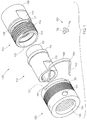
- Coupling system 100 includes a male portion 110 , a female portion 120 , a retaining member 130 , and a locking member 140 .
- An alternate locking member 150 may also be included in the system 100 .
- male portion 110 may include an insert portion 112 , a boss 114 , and a hose receiving portion 116 .
- Female portion 120 may include a receptacle portion 122 , threads 124 , a ridge 125 , a wrenching section 126 , locking groove 127 , and connection portion 128 .
- Retaining member 130 may include threads 132 , an abutment portion 134 , retainer orifice(s) 136 , a lip 137 , knurling 138 and a wrenching section 139 .
- Insert portion 112 , of male portion 110 may be capable of generally coupling with receptacle portion 122 of female portion 120 in a non-interference-type fit. Boss 114 may then generally provide a stop or may be adjacent to or abut female portion 120 . There may be created a seal between male portion 110 and female portion 120 , preferably between their cylindrical surfaces. This may allow fluid to pass therebetween.
- Female portion 120 may also include a seal groove 129 , which may be capable of retaining a seal such as an O-ring (not shown). This may be one configuration which may enhance the sealing ability of the coupling system 100 . Alternately, a seal groove capable of retaining a seal such as an O-ring may be included on male insert portion 112 .
- dust seal(s) (not shown) may be included, for example near ridge 125 or groove 127 or near abutment portion 134 , for example, in order to keep foreign matter out of the threads. It should be understood that ridge 125, aspects of groove 127, and lip 137 are optional and may be omitted or reconfigured as desired provided the requisite locking functionality is present.
- Retaining member 130 may then generally slide over male portion 110 , such that threads 132 of retaining member 130 may engage corresponding threads 124 of female portion 120 .
- Male portion 110 may generally extend through retaining member 130 .
- Boss 114 of male portion 110 may then be in contact with abutment portion 134 of retaining member 130 . This may secure together male portion 110, female portion 120 and retaining member 130 , and may enhance the sealing between male portion 110 and female portion 120 .
- extension(s) 142 of locking member 140 may extend through retainer orifice(s) 136 of retaining member 130 and engage female portion 120 at locking groove 127 such that retaining member may not uncouple from female portion 120 .
- Retaining member 130 is constructed to be hand tightened, but if there is an application that requires the male portion 110 and female portion 120 to be locked against a possible live swivel, torque may be applied to retaining member 130 similar to other threaded connection systems and methods. For a faster connection, multiple-start threads may be used.
- locking member 140 may include an indication portion 146 which may be made to be a visible color such as red, to indicate the coupling system 100 is engaged. This may be used as a safety indicator, and/or lockout to indicate if the coupling system is engaged and able to withstand pressure.
- locking member 140 may be of different configurations, such as locking member 150 .
- Locking member 150 may include an extrusion 152 which may be capable of extending through a retainer orifice 136 to engage locking groove 127 of female portion 120 to generally secure retaining member 130 to other portions of the system.
- Locking member 150 may also include indication portion 154 which be made to be a visible color and/or configuration such as red, to indicate the coupling system 100 is engaged, for safety and/or other reasons.
- the locking member is designed in the form of a special clip, staple, a snap-in button, or a wire threaded through the nut. This locking feature may not be able to be applied until the threads are fully-engaged, so it may be very clear by visual inspection as to whether a connection is properly made.
- holes 236 are drilled or formed roughly tangent to locking groove 127 within the retaining member 230.
- a plastic or metal wire tie 240 , or other locking member may be threaded through the holes 236 , engaging both locking groove 127 and a locking groove in retaining member 230 (not visible) thereby keeping the retaining member from backing off and providing a visual indication of a proper connection.
- the wire cable tie 240 shown in FIG. 5 is in the form of a cable seal which may be designed for single use (cut to remove) or multiple use. Seal or tag 246 provides further visual indication of a proper connection and may be labeled for various identification or record-keeping purposes. Likewise other kinds of metal or plastic ties or seals may be utilized which may be for single or multiple use, with or without an identification tag,
- coupling system 100 may be a coarse-thread connector which may be hand-tightened, having a locking feature that keeps retaining member 130 from backing off, and may further provide a visual indication of a proper connection via indication portion 146 , 154 , 246 of locking member 140 , 150 , 240 . Because the seal is generally along a cylinder, or between two cylinders, preload may not be required in the retaining member 130 , and it may not have a torque load requirement. Thus hand-tightening is sufficient to fully engage the coupling and withstand the design pressure.
- this coupling system 100 may provide a visual indicator of a proper connection.
- An advantage is a threaded retaining member 130 , which provides a mechanical advantage to draw the sealing cylinder in and out of female portion 120 for connection and removal.
- Male portion 110 may include a hose receiving portion 116 , which may be capable of receiving, and coupling to, a hose, manifold or other system or apparatus.
- hose receiving portion 116 may be generally in the form of a barb or other configuration capable of coupling to a hose.
- Portion 116 may also include a wrenching section to allow torque to be applied to the male portion 110 .
- Female portion 120 may also include a connection portion 128 which may be capable of coupling to a hose or manifold or other suitable structure. It will be appreciated that connection portion 128 may be of many forms to couple to various hoses and other structures. Female portion 120 may also include a wrenching portion 126 to allow torque to be applied to the female portion 120 .
- Retaining member 130 may also include knurling 138 or similar surface modification, which may enhance gripping and turning of retaining member 130 , especially during hand tightening.
- Retaining member 130 may also include wrenching adaptations such as a hex, holes, slots, flats, or orifice(s) 139 as shown, which are capable of receiving a wrench or other tool used to tighten/loosen and/or generally apply torque to said retaining member.
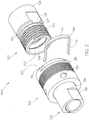
- FIG. 2 shows coupling system 100 with retaining member 130 slid over male portion 110, before coupling to female portion 110 .
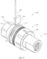
- FIG. 3 shows coupling system 100 fully engaged with retaining member 130 coupling together with male portion 120 and female portion 110 , with locking member 140 extending through retainer orifices 136 and engaging locking groove 127 (not shown).
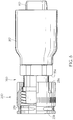
- FIG. 4 is a cut away view of a portion of coupling system 100 , according to an embodiment.
- retaining member 130 includes threads 132 which threadingly engage threads 124 of female portion 120 . This configuration does not allow retaining member 130 to unthread from female portion 120 when locking member 140 is in place between lip 137 and the side of groove 127 near the threads 124.
- Insert portion 112 of male portion 110 generally fits within, and is coupled to, receptacle portion 124 of female portion 120 .
- a first side of boss 114 may generally abut and/or be adjacent to female portion 110 .
- a second side of boss 114 may abut or generally be adjacent to abutment portion of retaining member 130 .
- the threading of retaining member 130 with female portion 120 may move and/or generally secure male portion 110 to female portion 120 and retaining member 130 , via abutment portion 134 .
- Coupling system 200 includes male portion 210 , coupled to female portion 220 , held together by retaining member 230 .
- locking member 240 is in the form of a cable seal with extending cable 242 threaded through tangential holes 236 with seal or tag 246 preventing unwanted removal and as additional visual indication the coupling is secure.
- Wrenching section 239 on retaining member 230 takes the form of a series of notches which may be suitable for use of a spanner wrench.
- Wrenching section 226 on female portion 220 takes the form of a hex nut. Retainer orifices in the form of tangential holes 236 are also shown on retaining member 230 in FIG. 6 .
- FIG. 6 shows an embodiment with male portion 310 having a hose receiving portion which includes hose barb 312 and ferrule 317 .
- Retaining member 230 may be slid over male portion into the position shown. Then ferrule 317 may be staked or swaged or otherwise attached in place as shown.
- the rear face 234 of retaining member 230 is in fairly close proximity to and opposes the front face 334 of the ferrule. Thus, when retaining member 230 is unthreaded from a coupled female portion, rear face 234 will abut front face 334 and thereby draw the male portion out of the female portion thus disconnecting the coupling.
- connection to pipes, hose or manifolds may be envisioned which provide the abutment needed to draw the male portion out of the female portion when the retaining member is unthreaded, such as a two-piece, stake-collar and ferrule arrangement.
- the hose receiving portion could be threaded for receiving a hydraulic fitting with mating threads.
- any mating female fitting that connects via such male threads on the connection portion may have a face equivalent to face 334 which can abut the end 234 of the retaining portion and thus facilitate disconnection.
- FIG. 7 shows an embodiment of the invention in which the external threads which correspond to the retaining member are on the male portion.
- coupling system 400 includes male portion 410 , female portion 420 and retaining member 430 .
- Female portion 420 has receptacle portion 422 .
- Insert portion 412 of male portion 410 fits into receptacle portion 422 with O-ring 425 housed in seal retaining groove 429 on insert portion 412 .
- the O-ring thus provides a seal between the male and female portions.
- Retaining member 430 has internal threads 432 which mate with external threads 424 on male portion 410 .
- Retaining member 430 has abutment portion 434 which abuts boss 414 when slipped over female portion 420 .
- retaining member 430 is threadingly engaged with the threads 424 on male portion 410 , the male portion may be drawn into sealing engagement with female portion 420 .
- locking member 240 shown as a cable tie, may be inserted through holes or openings or orifices in retaining member 430 and thus threaded around the coupling in a passageway defined by or between groove 427 on male portion 410 and lip 437 on retaining member 430 .
- seal placement(s) and type(s) including seal placement(s) and type(s), hose receiving portion(s), connection portion(s), wrenching section(s) or portion(s), knurling, orifice style, locking member type, and indication portion.
- the retaining member may be hand-tightened to pull the male sealing surface into the female with the seal there between.
- the cable tie or other locking member is inserted through holes in the retaining member into a groove in the female (or male, depending on the embodiment) and locked.
- the cable may be cut and/or pulled out and removed so that the retaining member can be loosened.
- the cable or locking member does not carry the pressure load. The threads carry the pressure load and therefore the design is capable of much higher pressure rating than a staple-lock coupling of similar diameter.
- the retaining member happens to back off enough during operation to resist the locking member pulling out, simply tightening the retaining member farther will eliminate this resistance.
- the cable or other locking device
- loosening or unthreading the retaining member may separate the fitting.
- a spanner wrench or other suitable tool may be used to turn the retaining member and release the fitting.
- the threaded retaining member may even provide enough mechanical advantage to overcome the resistance of debris and corrosion present at assembly or disassembly by hand.
- Coupling system 100, 200, 400 or other embodiment of the invention may overcome many issues of other threaded connections, such as assuring adequate preload in the retaining member to overcome the pressure load, easily damaged threads, and having no visual indication of complete connection. It also overcomes issues in non-threaded designs, such as high insertion force, unprotected seals, poor impulse performance, and installation of heavy locking devices such as hammer unions, clamshells or thick staples.
- the advantages of the invention include the ease of hand tightening or loosening, the greater safety factor of threads over conventional staples, no torque required to seal and hold, and less mass required to achieve a given rating.
- this system may be used with lower pressure systems. This may allow the use of less expensive materials and configurations.
- the system may be configured to connect hose, pipes, fittings, manifolds or the like.
- Systems disclosed herein may be used with, but are not limited to, 2-4" chemical hose, and/or with volume control regulators.
- the inventive coupling system offers advantages over hammer unions in the oil field industry, including those used for cementing hose, slim hole rotary hose, and the like.
- the locking member could be a c-clip inserted in a suitable groove adjacent a suitable flange.
- the locking method could be a frictional engagement, or it could be a bayonet style engagement or a latch, or multiple bayonets or latches.
Landscapes
- Engineering & Computer Science (AREA)
- General Engineering & Computer Science (AREA)
- Mechanical Engineering (AREA)
- Quick-Acting Or Multi-Walled Pipe Joints (AREA)
- Earth Drilling (AREA)
- Component Parts Of Construction Machinery (AREA)
- Automatic Assembly (AREA)
- Joints That Cut Off Fluids, And Hose Joints (AREA)
Claims (15)
- Kopplungssystem (100, 400), das Folgendes umfasst:einen aufzunehmenden Abschnitt (110, 410), der einen Einsatzabschnitt (112, 412) umfasst, der dazu ausgelegt ist, sich allgemein aneinander passend mit einem Aufnahmeabschnitt (122, 422) eines aufnehmenden Abschnitts (120, 420) des Kopplungssystems zu koppeln, wobei der aufzunehmende Abschnitt oder der aufnehmende Abschnitt in der Lage ist, sich durch ein von Hand festziehbares Halteelement (130, 430) des Kopplungssystems zu erstrecken;wobei das Halteelement Folgendes umfasst: Gewinde (132, 432), die sich windend mit entsprechenden Gewinden (124, 424) an dem jeweils anderen von aufzunehmendem Abschnitt bzw. aufnehmendem Abschnitt koppeln, einen Anschlagabschnitt (134, 434), der an eine Auswölbung (114, 414) an dem aufzunehmenden Abschnitt oder dem aufnehmenden Abschnitt angrenzt und dadurch den aufzunehmenden Abschnitt in den aufnehmenden Abschnitt zieht, wenn die Gewinde und die entsprechenden Gewinde windend gekoppelt werden, und eine Lippe (137, 437); undein Sperrelement (140, 240), das eine Verlängerung (142, 242) umfasst, wobei die Verlängerung in der Lage ist, sich allgemein durch ein oder mehrere Löcher (136, 236) in dem Halteelement zu erstrecken, und das ferner in der Lage ist, sich mit einer Sperrnut (127, 427) in dem jeweils anderen von aufzunehmendem Abschnitt und aufnehmendem Abschnitt zu koppeln, um ein Aufdrehen der Gewinde und der entsprechenden Gewinde zu hemmen, wenn sich das Sperrelement in seiner Position zwischen der Lippe und der Seite der Sperrnut in der Nähe der entsprechenden Gewinde befindet, wobei das Sperrelement einen Clip, eine Klammer, einen Rastknopf, einen Draht, einen Kabelbinder oder ein Kabel umfasst, dadurch gekennzeichnet, dass an einer Tangente zu der Sperrnut ein oder mehrere Löcher ausgebildet sind.
- Kopplungssystem (100) nach Anspruch 1, wobei sich der aufzunehmende Abschnitt (110) durch das Halteelement (130) erstreckt und die Gewinde (132) Innengewinde an dem Halteelement sind, und die entsprechenden Gewinde (124) Außengewinde an dem aufnehmenden Abschnitt (120) sind, und der Anschlagabschnitt (134) an die Auswölbung (114) an dem aufzunehmenden Abschnitt angrenzt, und die Sperrnut (127) an dem aufnehmenden Abschnitt (120) angeordnet ist.
- Kopplungssystem (400) nach Anspruch 1, wobei sich der aufnehmende Abschnitt (420) durch das Halteelement (430) erstreckt, wobei die Gewinde (432) Innengewinde an dem Halteelement (430) sind, und die entsprechenden Gewinde (424) Außengewinde an dem aufzunehmenden Abschnitt (410) sind, und der Anschlagabschnitt (434) an die Auswölbung (414) an dem aufnehmenden Abschnitt (420) angrenzt, und die Sperrnut (427) an dem aufzunehmenden Abschnitt (410) angeordnet ist.
- Kopplungssystem nach einem der Ansprüche 1 bis 3, wobei das Halteelement ferner eine Rändelung (138) umfasst, die in der Lage ist, die Fähigkeit zum Drehen des Halteelements von Hand beim windenden Koppeln oder Entkoppeln des Halteelements und des aufnehmenden Abschnitts zu verbessern.
- Kopplungssystem nach einem der Ansprüche 1 bis 3, wobei der aufzunehmende Abschnitt ferner einen Schlauchaufnahmeabschnitt (116) umfasst, der in der Lage ist, mit einem Schlauch, einem Rohr, einer Leitung und/oder einer Verzweigung gekoppelt zu werden.
- Kopplungssystem nach einem der Ansprüche 1 bis 3, wobei der aufnehmende Abschnitt ferner einen Verbindungsabschnitt (128) umfasst, der in der Lage ist, den aufnehmenden Abschnitt mit einem Schlauch, einem Rohr, einer Leitung und/oder einer Verzweigung zu verbinden.
- Kopplungssystem nach einem der Ansprüche 1 bis 3, wobei der aufnehmende Abschnitt ferner einen Festziehabschnitt (126) umfasst, der dazu ausgelegt ist, das Anziehen des aufnehmenden Abschnitts zu verbessern.
- Kopplungssystem nach einem der Ansprüche 1 bis 3, wobei der aufnehmende Abschnitt ferner eine Dichtungsnut (129) umfasst, die in der Lage ist, eine Dichtung allgemein zu halten, wobei die Dichtung vorzugsweise einen O-Ring umfasst.
- Kopplungssystem nach einem der Ansprüche 1 bis 3, wobei der aufzunehmende Abschnitt ferner eine Dichtungsnut umfasst, die eine Dichtung allgemein halten kann.
- Kopplungssystem nach einem der Ansprüche 1 bis 3, wobei das Sperrelement ferner einen Kennzeichnungsabschnitt (146) umfasst, der kennzeichnen kann, dass sich das Kopplungssystem in einer von Hand festgezogenen Position allgemein im Eingriff befindet.
- Verfahren des Koppelns eines oder mehrerer Schläuche unter Verwendung eines Kopplungssystems nach einem der vorangehenden Ansprüche, wobei das Verfahren Folgendes umfasst:Bereitstellen eines Kopplungssystems (100, 400), das einen aufzunehmenden Abschnitt (110, 410), einen aufnehmenden Abschnitt (120, 420), ein von Hand festziehbares Halteelement (130, 430) und ein Sperrelement (140, 240) umfasst, wobei das Sperrelement einen Clip, eine Klammer, einen Rastknopf, einen Draht, einen Kabelbinder oder ein Kabel umfasst;wobei der aufnehmende Abschnitt einen Einsatzabschnitt (112, 412) umfasst, der dazu ausgelegt ist, sich aneinander passend mit einem Aufnahmeabschnitt (122, 422) des aufnehmenden Abschnitts des Kopplungssystems zu koppeln,ein Sich-Erstrecken des aufzunehmenden Abschnitts oder des aufnehmenden Abschnitts durch das Halteelement, sodass ein Anschlagabschnitt des Halteelements an eine Auswölbung (114, 414) an dem aufzunehmenden Abschnitt oder dem aufnehmenden Abschnitt angrenzt;ein windendes Koppeln der Innengewinde an dem Halteelement mit entsprechenden Außengewinden an dem anderen von aufzunehmendem Abschnitt und aufnehmendem Abschnitt, wobei das Halteelement den aufzunehmenden Abschnitt in ein abdichtendes Eingreifen mit dem aufnehmenden Abschnitt zieht; undEingreifen des Sperrelements durch Einsetzen einer Verlängerung des Sperrelements durch ein Loch in dem Halteelement zwischen der Lippe und der Seite der Sperrnut in der Nähe der entsprechenden Gewinde, wodurch ein Aufdrehen der Gewinde und der entsprechenden Gewinde gehemmt wird, wobei die Löcher auf einer Tangente zu der Sperrnut ausgebildet sind.
- Verfahren nach Anspruch 11, das ferner das Herstellen der Dichtung zwischen dem aufzunehmenden Abschnitt und dem aufnehmenden Abschnitt mindestens teilweise über eine Dichtungsnut in dem Aufnahmeabschnitt umfasst, wobei das Herstellen einer Dichtung ferner eine Dichtung umfasst, die allgemein dazu ausgelegt ist, in der Dichtungsnut gehalten zu werden.
- Verfahren nach Anspruch 11, das ferner ein vollständiges Festziehen von Hand über die Rändelung umfasst, wenn das Halteelement und der aufnehmende Abschnitt windend gekoppelt werden.
- Verfahren nach Anspruch 11, das ferner ein Koppeln des aufzunehmenden Abschnitts mit einem Schlauch, einer Leitung und/oder einer Verzweigung über einen Schlauchaufnahmeabschnitt des aufzunehmenden Abschnitts oder ein Koppeln des aufnehmenden Abschnitts an einen Schlauch, eine Leitung und/oder eine Verzweigung über einen Verbindungsabschnitt des aufnehmenden Abschnitts umfasst, oder das ein Anziehen des aufnehmenden Abschnitts über einen Festziehabschnitt umfasst.
- Verfahren nach Anspruch 11, ferner umfassend das Kennzeichnen, dass sich das Kopplungssystem allgemein mindestens teilweise im Eingriff befindet, wozu ein Kennzeichnungsabschnitt des Sperrelements dient.
Priority Applications (1)
| Application Number | Priority Date | Filing Date | Title |
|---|---|---|---|
| PL12814077T PL2800920T3 (pl) | 2011-12-26 | 2012-12-18 | Złączka hydrauliczna ręcznie dokręcana |
Applications Claiming Priority (3)
| Application Number | Priority Date | Filing Date | Title |
|---|---|---|---|
| US201161580269P | 2011-12-26 | 2011-12-26 | |
| US13/675,109 US9803783B2 (en) | 2011-12-26 | 2012-11-13 | Hand tightened hydraulic fitting |
| PCT/US2012/070239 WO2013101534A1 (en) | 2011-12-26 | 2012-12-18 | Hand tightened hydraulic fitting |
Publications (2)
| Publication Number | Publication Date |
|---|---|
| EP2800920A1 EP2800920A1 (de) | 2014-11-12 |
| EP2800920B1 true EP2800920B1 (de) | 2019-02-20 |
Family
ID=48653771
Family Applications (1)
| Application Number | Title | Priority Date | Filing Date |
|---|---|---|---|
| EP12814077.9A Active EP2800920B1 (de) | 2011-12-26 | 2012-12-18 | Von hand festziehbarer hydraulikanschluss |
Country Status (11)
| Country | Link |
|---|---|
| US (6) | US9803783B2 (de) |
| EP (1) | EP2800920B1 (de) |
| CN (1) | CN103339432B (de) |
| AU (5) | AU2012362800B2 (de) |
| CA (1) | CA2859196C (de) |
| MX (2) | MX2014007810A (de) |
| PL (1) | PL2800920T3 (de) |
| RU (2) | RU2581299C2 (de) |
| UA (3) | UA111402C2 (de) |
| WO (1) | WO2013101534A1 (de) |
| ZA (2) | ZA201403856B (de) |
Cited By (1)
| Publication number | Priority date | Publication date | Assignee | Title |
|---|---|---|---|---|
| US11460137B2 (en) | 2020-03-12 | 2022-10-04 | Parker-Hannifin Corporation | Fluid connection systems |
Families Citing this family (82)
| Publication number | Priority date | Publication date | Assignee | Title |
|---|---|---|---|---|
| WO2012104179A2 (de) * | 2011-02-01 | 2012-08-09 | Parker Hannifin Manufacturing Germany GmbH & Co. KG | Verbindungsvorrichtung für rohr- oder schlauchleitungen mit montageerkennung |
| WO2013052091A1 (en) | 2011-10-03 | 2013-04-11 | Entegris, Inc. | Modular filtration system |
| US9803783B2 (en) * | 2011-12-26 | 2017-10-31 | Gates Corporation | Hand tightened hydraulic fitting |
| US9296075B2 (en) * | 2012-03-08 | 2016-03-29 | Acument Intellectual Properties, Llc | Die case extractor and method |
| EP2904300A1 (de) | 2012-10-01 | 2015-08-12 | Entegris, Inc. | Verbindungssystem und verfahren |
| US9618704B2 (en) * | 2013-07-31 | 2017-04-11 | Corning Optical Communications LLC | Fiber optic connector sub-assemblies having a front-loading locking ferrule holder and related fiber optic components, devices and methods |
| US11262013B2 (en) | 2014-01-14 | 2022-03-01 | The Boeing Company | Tube fitting |
| US10359141B2 (en) * | 2014-01-14 | 2019-07-23 | The Boeing Company | Tube fitting |
| USD749702S1 (en) * | 2014-02-06 | 2016-02-16 | David M. Rohn | Drain pipe discharge connector |
| FR3017688B1 (fr) * | 2014-02-14 | 2016-11-25 | Sartorius Stedim Fmt Sas | Ensemble de raccordement fluidique modulaire. |
| GB2524056B (en) | 2014-03-13 | 2016-11-02 | Adey Holdings 2008 Ltd | Connection assembly |
| DE102014108699A1 (de) * | 2014-06-20 | 2015-12-24 | Alfred Kärcher Gmbh & Co. Kg | Kupplungsanordnung für schraubkupplung |
| USD771480S1 (en) * | 2014-09-26 | 2016-11-15 | Gregory E. Lowitz | Caliper crack mark |
| CN110778818A (zh) * | 2014-10-09 | 2020-02-11 | 可得制品公司 | 具有固位夹子构件的联接组件 |
| US9822913B2 (en) * | 2015-03-16 | 2017-11-21 | Caterpillar Inc. | Quick connector for hydraulic hose coupling |
| US12020598B2 (en) * | 2015-05-01 | 2024-06-25 | Direct Purchase Quick Couplings, Incorporated | Color identification safety system |
| US10202907B2 (en) | 2015-06-24 | 2019-02-12 | Continental Automotive Systems, Inc. | Screw on throttle body adapter |
| US10738922B2 (en) | 2015-08-27 | 2020-08-11 | Caterpillar Inc. | Fluid conduit connection system with a double undercut clamp |
| FR3044724B1 (fr) * | 2015-12-03 | 2018-04-13 | Safran Helicopter Engines | Dispositif de limitation de desserrage d'un ecrou dans une turbomachine |
| US10627026B2 (en) | 2015-12-10 | 2020-04-21 | 3SC Global, LLC | Fittings, components, and associated tools |
| USD822180S1 (en) * | 2016-03-10 | 2018-07-03 | Mustang Sampling, Llc | Pipe fitting |
| US10899503B2 (en) | 2016-04-20 | 2021-01-26 | Yeti Coolers, Llc | Spigot and spigot guard for an insulating container |
| US10138047B2 (en) | 2016-04-20 | 2018-11-27 | Yeti Coolers, Llc | Spigot and spigot guard for an insulating container |
| US10046885B2 (en) | 2016-04-20 | 2018-08-14 | Yeti Coolers, Llc | Spigot and spigot guard for an insulating container |
| US10526130B2 (en) | 2016-04-20 | 2020-01-07 | Yeti Coolers, Llc | Insulating container |
| CN107509353A (zh) * | 2016-06-14 | 2017-12-22 | 伊姆西公司 | 用于机架的杆以及与机架配合使用的固定装置 |
| US10883640B2 (en) | 2016-06-24 | 2021-01-05 | Eaton Intelligent Power Limited | Fluid couplings, systems, and methods |
| US11149883B2 (en) | 2016-06-24 | 2021-10-19 | Eaton Intelligent Power Limited | Fluid couplings, systems, and methods |
| DE102017100357A1 (de) * | 2017-01-10 | 2018-07-12 | Alfred Kärcher Gmbh & Co. Kg | Kupplungsanordnung für schraubkupplung |
| USD817760S1 (en) * | 2017-02-03 | 2018-05-15 | Integrated Liner Technologies, Inc. | Magnetic cap |
| USD839661S1 (en) | 2017-07-12 | 2019-02-05 | Yeti Coolers, Llc | Container mounting apparatus |
| USD830122S1 (en) * | 2017-07-12 | 2018-10-09 | Yeti Coolers, Llc | Dispenser |
| USD835946S1 (en) | 2017-07-12 | 2018-12-18 | Yeti Coolers, Llc | Container |
| USD835947S1 (en) | 2017-07-12 | 2018-12-18 | Yeti Coolers, Llc | Container mounting apparatus |
| USD835471S1 (en) | 2017-07-12 | 2018-12-11 | Yeti Coolers, Llc | Container |
| USD835470S1 (en) | 2017-07-12 | 2018-12-11 | Yeti Coolers, Llc | Container |
| USD835472S1 (en) | 2017-07-12 | 2018-12-11 | Yeti Coolers, Llc | Combined container mounting apparatus and container |
| USD830123S1 (en) | 2017-07-12 | 2018-10-09 | Yeti Coolers, Llc | Dispenser |
| USD859618S1 (en) | 2017-09-15 | 2019-09-10 | Pentair Water Pool And Spa, Inc. | Heating apparatus clip |
| US10704723B2 (en) | 2017-09-20 | 2020-07-07 | Gates Corporation | Quick disconnect coupling |
| US10672449B2 (en) | 2017-10-20 | 2020-06-02 | Micron Technology, Inc. | Apparatus and methods for refreshing memory |
| USD843180S1 (en) | 2017-10-25 | 2019-03-19 | Yeti Coolers, Llc | Container mounting apparatus |
| RU2686411C1 (ru) * | 2018-04-18 | 2019-04-25 | Публичное акционерное общество "Татнефть" имени В.Д. Шашина | Съемник |
| WO2020040841A1 (en) | 2018-08-21 | 2020-02-27 | Parker-Hannifin Corporation | Fluid connector |
| USD909532S1 (en) * | 2018-12-11 | 2021-02-02 | Armaturenwerk Hoetensleben Gmbh | Nozzle |
| USD897494S1 (en) * | 2018-12-11 | 2020-09-29 | Armaturenwerk Hoetensleben Gmbh | Nozzle |
| WO2020142710A1 (en) * | 2019-01-03 | 2020-07-09 | Mega Fluid Systems, Inc. | Insert fitting devices, assemblies and couplings |
| USD911489S1 (en) * | 2019-03-05 | 2021-02-23 | The Fountainhead Group, Inc. | Liquid spray nozzle |
| USD900283S1 (en) * | 2019-03-05 | 2020-10-27 | The Fountainhead Group, Inc. | Adapter for a liquid spray nozzle |
| USD936785S1 (en) * | 2019-03-05 | 2021-11-23 | The Fountainhead Group, Inc. | Adapter for a liquid spray nozzle |
| USD883446S1 (en) * | 2019-03-05 | 2020-05-05 | The Fountainhead Group, Inc. | Adapter for a liquid spray nozzle |
| USD883445S1 (en) * | 2019-03-05 | 2020-05-05 | The Fountainhead Group, Inc. | Adapter for a liquid spray nozzle with a weed guard |
| US11209106B2 (en) * | 2019-03-22 | 2021-12-28 | General Electric Company | Self-locking fluid coupling assembly |
| USD886943S1 (en) * | 2019-03-28 | 2020-06-09 | Outdoor Trading LLC | Nozzle |
| RU192259U1 (ru) * | 2019-05-06 | 2019-09-11 | Дмитрий Геннадьевич Бобов | Устройство для соединения трубопроводов |
| DE102019004659A1 (de) * | 2019-07-02 | 2021-01-07 | Bomag Gmbh | Armatursicherung für hydraulikschlauchkupplungen, baumaschine und verfahren |
| USD983534S1 (en) * | 2019-09-18 | 2023-04-18 | Rps Corporation | Brush insert |
| USD980391S1 (en) * | 2019-10-28 | 2023-03-07 | Zurn Industries, Llc | Valve tamper shield |
| TWD204515S (zh) | 2019-11-05 | 2020-05-01 | 王志雄 | 緊迫內束裝置 |
| CN111255679A (zh) * | 2020-02-28 | 2020-06-09 | 华域视觉科技(上海)有限公司 | 液压接口转换装置、电子水泵水嘴转换安装结构及汽车 |
| CN111271533A (zh) * | 2020-03-25 | 2020-06-12 | 上海毫厘机电科技有限公司 | 一种用于宝塔式水接头的快速耐压密封装置 |
| CN111810738A (zh) * | 2020-06-23 | 2020-10-23 | 肖云东 | 一种密封扣油管短接 |
| USD1012228S1 (en) * | 2020-08-31 | 2024-01-23 | X-Virus Llc | Disinfectant misting fixture |
| US12152706B2 (en) | 2020-09-21 | 2024-11-26 | Abc Technologies Inc. | Pipe coupling |
| EP4305333A1 (de) * | 2021-03-09 | 2024-01-17 | ABC Technologies Inc. | Schnellverbindungsrohrkupplung |
| USD973849S1 (en) | 2021-03-16 | 2022-12-27 | Mustang Sampling, Llc | Pipe fitting |
| US12025255B2 (en) | 2021-04-23 | 2024-07-02 | Eaton Intelligent Power Limited | Quick action fluid coupler |
| USD1030670S1 (en) * | 2021-06-17 | 2024-06-11 | Telebrands Corp. | Connector |
| US12031780B2 (en) | 2021-08-11 | 2024-07-09 | Hoffman Enclosures Inc. | Liquid manifold for electronics cabinet |
| USD1032783S1 (en) * | 2021-11-10 | 2024-06-25 | Telebrands Corp. | Nozzle |
| FR3132940B1 (fr) * | 2022-02-24 | 2024-03-15 | Safran Aircraft Engines | Elément de liaison d’un tube de canalisation à un support de palier et turbomachine équipée d’un tel élément de liaison. |
| USD1073932S1 (en) * | 2022-05-23 | 2025-05-06 | Passy-Muir, Inc. | Tracheostomy occlusion adapter |
| CN115289288A (zh) * | 2022-08-05 | 2022-11-04 | 深圳市欣普斯科技有限公司 | 液冷散热泵及其管接头连接结构 |
| USD1043909S1 (en) * | 2022-11-11 | 2024-09-24 | Winston Products Llc | Nozzle |
| IL301148B2 (en) * | 2023-03-05 | 2024-03-01 | Ham Let | Containment connector |
| USD1065441S1 (en) * | 2023-07-03 | 2025-03-04 | Ningbo Tycoon Import And Export Co., Ltd. | Sprayer |
| TWI839276B (zh) * | 2023-07-24 | 2024-04-11 | 徐鵬鈞 | 內外牙接頭迫緊器 |
| DE102023122905A1 (de) * | 2023-08-25 | 2025-02-27 | Truedyne Sensors AG | Vorrichtung zur lösbaren Verbindung einer ersten rohrförmigen Komponente und einer zweiten rohrförmigen Komponente |
| EP4545789A1 (de) * | 2023-10-23 | 2025-04-30 | Wilo Se | Umleitungsanordnung zum anschluss an ein hydrauliksystem und verfahren zum entfernen und/oder austauschen eines verschleissteils und/oder zum entfernen und/oder austauschen |
| USD1120211S1 (en) * | 2024-01-24 | 2026-03-24 | Demaclenko It S.R.L. | Snow gun |
| JP1774853S (ja) * | 2024-02-26 | 2024-07-05 | 管継手 | |
| CN118309855B (zh) * | 2024-04-15 | 2024-09-17 | 珠海吉泰克物理科技有限公司 | 一种分体式热泵室内机管道连接结构 |
Family Cites Families (96)
| Publication number | Priority date | Publication date | Assignee | Title |
|---|---|---|---|---|
| US410780A (en) * | 1889-09-10 | Maurice cah | ||
| US904673A (en) * | 1905-06-27 | 1908-11-24 | William E Bideker | Nozzle-tip. |
| US1815500A (en) * | 1930-03-17 | 1931-07-21 | Elmer M Doan | Stud extractor |
| US2178298A (en) | 1937-10-15 | 1939-10-31 | Mueller Co | Inserting tool |
| US2247427A (en) | 1938-10-15 | 1941-07-01 | Mueller Co | Corporation stop and tool |
| US2598109A (en) | 1949-12-27 | 1952-05-27 | Oster Mfg Co | Nipple chuck |
| US2880019A (en) | 1955-08-15 | 1959-03-31 | Federal Mogul Bower Bearings | Pipe joint having a reinforced extrusion-resistant gasket |
| US2916813A (en) * | 1955-11-18 | 1959-12-15 | Edgar E Belanger | Blind dowel extractor |
| US2933960A (en) * | 1957-06-10 | 1960-04-26 | Studrive Inc | Stud driving chuck |
| FR1221842A (fr) | 1959-01-15 | 1960-06-03 | Perfectionnements apportés aux dispositifs de raccords, notamment pour tuyaux | |
| US3104569A (en) * | 1961-03-20 | 1963-09-24 | Donald B Davis | Stud bolt remover |
| US3201149A (en) | 1961-12-01 | 1965-08-17 | Parker Hannifin Corp | Tube coupling |
| DE1478853A1 (de) | 1963-10-17 | 1969-09-04 | Wilhelm Dommer | Rohrschraubenschluessel fuer eingeputzte Rohrstuecke,insbesondere Fittings |
| US3292463A (en) | 1966-01-10 | 1966-12-20 | Titan Tool Co | Wrench adapter |
| US3446245A (en) | 1966-02-28 | 1969-05-27 | Srm Co | Threaded fluid coupling |
| US3332710A (en) * | 1966-08-03 | 1967-07-25 | Chevron Res | Flanged pipes with low clamping stress |
| US3529497A (en) * | 1968-06-27 | 1970-09-22 | Daryl G Brooks | Dowel removing tool |
| US3615109A (en) | 1969-08-14 | 1971-10-26 | Gregory Brinda | Coupler fitting for use with both vacuum and pressure systems |
| US3740814A (en) * | 1971-06-03 | 1973-06-26 | C Marshall | Stud extractor |
| US3718058A (en) * | 1971-07-16 | 1973-02-27 | Borg Warner | Camlock threaded stud actuator |
| US3727491A (en) * | 1971-11-26 | 1973-04-17 | S Buckwalter | Stud bolt puller and inserter |
| US3805863A (en) * | 1972-01-17 | 1974-04-23 | Hi Shear Corp | Threaded pin-collar system with retention means |
| US3777356A (en) | 1972-04-04 | 1973-12-11 | J Hemingway | Pipe nipple tool |
| US4043575A (en) * | 1975-11-03 | 1977-08-23 | The Rucker Company | Riser connector |
| US4068866A (en) * | 1976-03-25 | 1978-01-17 | Mueller Co. | Stab-type joint for smooth end or flareless pipe |
| US4135742A (en) * | 1977-02-10 | 1979-01-23 | Rockwell International Corporation | Adjustable tube coupling |
| JPS53105718A (en) | 1977-02-28 | 1978-09-14 | Hitachi Ltd | Lock device of union joint |
| US4165106A (en) * | 1977-09-26 | 1979-08-21 | Gladden James B | Hose or pipe coupling |
| US4801160A (en) * | 1981-09-17 | 1989-01-31 | Michael J. Caddell | High-pressure fluid flow connector |
| US4624323A (en) * | 1985-02-07 | 1986-11-25 | Burrola Henry G | Multi-purpose impact hand tool kit |
| USD299267S (en) * | 1985-04-15 | 1989-01-03 | Claber S.P.A. | Quick-connect coupling |
| CA1249738A (en) * | 1985-08-29 | 1989-02-07 | Michael A. Rachanski | Stud installer |
| US4671141A (en) * | 1985-09-18 | 1987-06-09 | New Ideas Incorporated | Rotary torque device |
| USD296530S (en) * | 1985-10-11 | 1988-07-05 | Trutek Research, Inc. | Flow sensor |
| USD296581S (en) * | 1985-11-27 | 1988-07-05 | Suncast Corporation | Sleeve for hose connector |
| US5678607A (en) | 1986-01-15 | 1997-10-21 | Krywitsky; Lee A. | Reusable pipe union and pipe cap assembly for wide thermal cycling |
| DE3709819A1 (de) * | 1986-05-12 | 1987-11-19 | Waluga Armaturen | Rohrverschraubung |
| US4776618A (en) | 1987-08-14 | 1988-10-11 | Marathon Oil Company | High pressure coupling |
| DE3743170C1 (en) | 1987-12-19 | 1989-05-18 | Karl Dipl-Ing Weinhold | Pipe screw-connection |
| USD334617S (en) * | 1988-05-03 | 1993-04-06 | Claber S.P.A. | Quick-connect coupling |
| US4919456A (en) * | 1989-04-10 | 1990-04-24 | Otis Engineering Corporation | Union for pipe or tree with metal and resilient seals |
| US4940370A (en) * | 1989-10-16 | 1990-07-10 | Gipson Gregory L | Inner lug removal tool |
| USD325775S (en) * | 1989-10-19 | 1992-04-28 | L. R. Nelson Corporation | Hose quick connector housing |
| USD327314S (en) * | 1989-10-19 | 1992-06-23 | L. R. Nelson Corporation | Hose quick connector housing |
| US5060988A (en) | 1990-05-08 | 1991-10-29 | Nwd International, Inc. | Hydraulic coupling |
| US5131695A (en) * | 1991-03-13 | 1992-07-21 | Chatleff Controls, Inc. | Coupling with teflon seat |
| US5188398A (en) | 1992-01-02 | 1993-02-23 | General Electric Company | Redundantly locked fluid coupling |
| US5224515A (en) * | 1992-01-30 | 1993-07-06 | Porex Technologies Corp. | Tube closure |
| USD347263S (en) * | 1993-03-31 | 1994-05-24 | Reebok International Ltd. | Combined cover and connector for use with an inflation mechanism for athletic equipment |
| US5348349A (en) * | 1993-11-22 | 1994-09-20 | Sloane Norman S | Splined safety lock |
| US5498042A (en) * | 1994-06-20 | 1996-03-12 | Victauli Company Of America | Quick connect connector for grooved pipe |
| USD375843S (en) * | 1995-09-18 | 1996-11-26 | The Decor Corporation Pty Ltd | Broom handle connector |
| EP0851801A4 (de) * | 1995-09-20 | 1999-06-02 | David L Hildebrand | Vorrichtung zum lösen von mit gewinde versehenen verbindungsstücken |
| WO1997028396A1 (en) * | 1996-01-29 | 1997-08-07 | Sloane Norman S | Splined safety lock with resilient retaining ring |
| US5725259A (en) | 1996-12-19 | 1998-03-10 | Dials; Carroll P. | Conduit coupling |
| DE19713202C1 (de) | 1997-03-28 | 1998-06-04 | Weinhold Karl | Rohrkupplung |
| USD410529S (en) * | 1998-01-05 | 1999-06-01 | Taylor Julian S | In-line fluid flow control valve |
| DE19803732C2 (de) * | 1998-01-30 | 2000-10-26 | Audi Ag | Abziehvorrichtung für einen in ein Basisteil eingepreßten Stift |
| US5957509A (en) * | 1998-10-16 | 1999-09-28 | Komolrochanaporn; Naris | Pipe coupling |
| AU137931S (en) * | 1999-02-03 | 1999-07-28 | Davies | Adaptor sleeve |
| DE19906126C2 (de) * | 1999-02-13 | 2000-11-30 | Daimler Chrysler Aerospace | Einrichtung und Verfahren zum Lösen von Verbindungsbolzen |
| USD433928S (en) * | 1999-11-23 | 2000-11-21 | Alcone Jerry M | Header bolt assembly |
| US6976817B1 (en) * | 1999-12-30 | 2005-12-20 | Grainger Phillip T | Positive locking fastener |
| US6818076B1 (en) * | 2000-03-23 | 2004-11-16 | Ormco Corporation | Multi-strand coil spring |
| US6811189B1 (en) * | 2000-10-04 | 2004-11-02 | Grant Prideco, L.P. | Corrosion seal for threaded connections |
| US6375815B1 (en) * | 2001-02-17 | 2002-04-23 | David Mark Lynn | Cylindrical magnetron target and apparatus for affixing the target to a rotatable spindle assembly |
| USD463537S1 (en) * | 2001-06-08 | 2002-09-24 | Nitto Kohki Co., Ltd. | Plug of pipe coupling |
| US7140087B1 (en) * | 2001-09-06 | 2006-11-28 | Reconnx, Inc. | Methods for extracting fasteners from a host material |
| US6877401B1 (en) * | 2001-09-06 | 2005-04-12 | Reconnx, Inc. | Apparatus for extracting fasteners from a host material |
| RU23404U1 (ru) * | 2001-12-03 | 2002-06-20 | Государственный космический научно-производственный центр им. М.В. Хруничева | Устройство для выворачивания резьбовых втулок |
| US6789584B2 (en) * | 2002-03-26 | 2004-09-14 | Charles B. Linam | Fluid containment apparatus |
| NO319635B1 (no) * | 2002-08-19 | 2005-09-05 | Marine Direct Consultants Ltd | Anordning for sammenkopling av ror. |
| US6908119B2 (en) | 2002-09-26 | 2005-06-21 | Lewis-Goetz And Company, Inc. | Detachable hose coupling with an improved female and male coupling having an interlocking U-shaped staple |
| UA1902U (uk) | 2002-10-18 | 2003-07-15 | Товариство З Обмеженою Відповідальністю "Харківське Підприємство Упроваджування Нової Техніки" | З'єднання трубопроводів |
| US7635365B2 (en) * | 2003-08-28 | 2009-12-22 | Ellis Thomas J | Bone plates |
| US8006529B2 (en) * | 2003-09-12 | 2011-08-30 | Dreamwell, Ltd. | Methods for manufacturing coil springs |
| CN2734418Y (zh) | 2004-08-20 | 2005-10-19 | 扬动股份有限公司 | 双头螺柱装配用套筒 |
| AU2005203743B1 (en) | 2005-01-21 | 2006-02-02 | Jody Horan | A Plug for a Hydraulic Fitting |
| US20060186188A1 (en) * | 2005-02-23 | 2006-08-24 | Ronald Belanger | Mailbox protective device |
| USD595750S1 (en) | 2006-12-15 | 2009-07-07 | Sandvik Intellectual Property Ab | Cutting insert element |
| TWM323375U (en) * | 2007-07-04 | 2007-12-11 | Leader Union Entpr Co Ltd | Reversible and steady force-application anti-skid socket |
| UA25610U (en) | 2007-04-23 | 2007-08-10 | Public Corp Mykolaiv Works Of | Connection of pipelines |
| US7849575B2 (en) * | 2007-09-20 | 2010-12-14 | Schlem Products, Inc. | Seal removal tool and method |
| WO2009046433A2 (en) * | 2007-10-05 | 2009-04-09 | Hydra-Flex, Inc. | Chemical delivery system |
| US8001995B2 (en) * | 2008-06-23 | 2011-08-23 | Gregory Molloy | End cap for a hydraulic fitting |
| USD648008S1 (en) * | 2010-05-10 | 2011-11-01 | Strahman Valves, Inc. | Coupling |
| TWD142959S1 (zh) * | 2010-05-31 | 2011-10-01 | 旭化成化學股份有限公司 | 浸漬膜過濾機用之管接頭 |
| AU334621S (en) * | 2010-05-31 | 2011-01-17 | Asahi Kasei Chemicals Corp | Pipe fitting for a filter |
| US8857863B1 (en) * | 2010-08-04 | 2014-10-14 | Supreme Service & Specialty Co., Inc. | Method and apparatus for connecting conduit |
| US9140399B2 (en) * | 2010-10-06 | 2015-09-22 | Parker-Hannifin Corporation | Quick coupling |
| US20120086201A1 (en) | 2010-10-12 | 2012-04-12 | Joseph Stevenson Murken | Detachable hose coupling and staple remover |
| USD711516S1 (en) * | 2011-12-09 | 2014-08-19 | John Guest International Limited | Fluid connector |
| US9803783B2 (en) * | 2011-12-26 | 2017-10-31 | Gates Corporation | Hand tightened hydraulic fitting |
| US8657343B2 (en) * | 2012-02-06 | 2014-02-25 | Watts Water Technologies, Inc. | Quick connector assembly |
| USD745117S1 (en) * | 2013-06-07 | 2015-12-08 | Willard Joseph Ramey | Fittings assembly for temporary and tight joining of ends of tubular members |
| USD736358S1 (en) * | 2013-11-12 | 2015-08-11 | Teknor Apex Company | Female hose couplings |
-
2012
- 2012-11-13 US US13/675,109 patent/US9803783B2/en active Active
- 2012-12-18 RU RU2014131049/06A patent/RU2581299C2/ru active
- 2012-12-18 MX MX2014007810A patent/MX2014007810A/es not_active Application Discontinuation
- 2012-12-18 CN CN201280004442.2A patent/CN103339432B/zh active Active
- 2012-12-18 WO PCT/US2012/070239 patent/WO2013101534A1/en not_active Ceased
- 2012-12-18 UA UAA201408434A patent/UA111402C2/uk unknown
- 2012-12-18 CA CA2859196A patent/CA2859196C/en active Active
- 2012-12-18 PL PL12814077T patent/PL2800920T3/pl unknown
- 2012-12-18 AU AU2012362800A patent/AU2012362800B2/en active Active
- 2012-12-18 EP EP12814077.9A patent/EP2800920B1/de active Active
-
2013
- 2013-03-15 US US29/449,856 patent/USD738470S1/en active Active
- 2013-06-27 US US13/929,593 patent/US9939090B2/en active Active
- 2013-09-06 AU AU201315670F patent/AU352426S/en not_active Expired - Lifetime
- 2013-09-06 AU AU201315669F patent/AU352425S/en not_active Expired - Lifetime
- 2013-09-06 AU AU201314443F patent/AU352243S/en not_active Expired - Lifetime
- 2013-09-06 AU AU201315668F patent/AU352424S/en not_active Expired - Lifetime
- 2013-09-13 UA UAS201302728F patent/UA28786S/uk unknown
-
2014
- 2014-05-27 ZA ZA2014/03856A patent/ZA201403856B/en unknown
- 2014-06-25 UA UAA201600628A patent/UA116568C2/uk unknown
- 2014-06-25 RU RU2016102325A patent/RU2635054C2/ru active
- 2014-06-25 MX MX2015017705A patent/MX383951B/es unknown
-
2015
- 2015-07-23 US US29/533,966 patent/USD787647S1/en active Active
- 2015-07-23 US US29/533,972 patent/USD777299S1/en active Active
- 2015-11-16 ZA ZA2015/08455A patent/ZA201508455B/en unknown
-
2018
- 2018-02-26 US US15/905,369 patent/US10174873B2/en active Active
Non-Patent Citations (1)
| Title |
|---|
| None * |
Cited By (1)
| Publication number | Priority date | Publication date | Assignee | Title |
|---|---|---|---|---|
| US11460137B2 (en) | 2020-03-12 | 2022-10-04 | Parker-Hannifin Corporation | Fluid connection systems |
Also Published As
Similar Documents
| Publication | Publication Date | Title |
|---|---|---|
| EP2800920B1 (de) | Von hand festziehbarer hydraulikanschluss | |
| CA2493695C (en) | Pipe coupling | |
| US4834423A (en) | Quick connect fluid fitting assembly | |
| MX2014010852A (es) | Empalme con mecanismo de extraccion. | |
| US7726700B2 (en) | Pipe coupling | |
| EP2902686A1 (de) | Rohrverbindung | |
| CA2912467C (en) | Extraction device for removing an adapter secured in a port | |
| US7021392B2 (en) | Body with couplings | |
| US8746751B2 (en) | Quick connect coupling systems with insert | |
| US20090026760A1 (en) | Hose coupling assembly | |
| US7600790B2 (en) | Coupling assembly with connection indicator | |
| US7014224B1 (en) | Fluid line connector | |
| US20210180730A1 (en) | Hammerless pipe union | |
| US20060163872A1 (en) | Pipe coupling |
Legal Events
| Date | Code | Title | Description |
|---|---|---|---|
| PUAI | Public reference made under article 153(3) epc to a published international application that has entered the european phase |
Free format text: ORIGINAL CODE: 0009012 |
|
| 17P | Request for examination filed |
Effective date: 20140728 |
|
| AK | Designated contracting states |
Kind code of ref document: A1 Designated state(s): AL AT BE BG CH CY CZ DE DK EE ES FI FR GB GR HR HU IE IS IT LI LT LU LV MC MK MT NL NO PL PT RO RS SE SI SK SM TR |
|
| DAX | Request for extension of the european patent (deleted) | ||
| 17Q | First examination report despatched |
Effective date: 20160318 |
|
| STAA | Information on the status of an ep patent application or granted ep patent |
Free format text: STATUS: EXAMINATION IS IN PROGRESS |
|
| REG | Reference to a national code |
Ref country code: DE Ref legal event code: R079 Ref document number: 602012056886 Country of ref document: DE Free format text: PREVIOUS MAIN CLASS: F16L0019000000 Ipc: F16L0021080000 |
|
| GRAP | Despatch of communication of intention to grant a patent |
Free format text: ORIGINAL CODE: EPIDOSNIGR1 |
|
| RIC1 | Information provided on ipc code assigned before grant |
Ipc: F16B 39/00 20060101ALI20180611BHEP Ipc: F16L 19/02 20060101ALI20180611BHEP Ipc: F16L 19/00 20060101ALI20180611BHEP Ipc: F16L 21/08 20060101AFI20180611BHEP Ipc: F16L 23/00 20060101ALI20180611BHEP Ipc: F16B 39/10 20060101ALI20180611BHEP Ipc: F16B 39/02 20060101ALI20180611BHEP |
|
| STAA | Information on the status of an ep patent application or granted ep patent |
Free format text: STATUS: GRANT OF PATENT IS INTENDED |
|
| INTG | Intention to grant announced |
Effective date: 20180719 |
|
| GRAS | Grant fee paid |
Free format text: ORIGINAL CODE: EPIDOSNIGR3 |
|
| RAP1 | Party data changed (applicant data changed or rights of an application transferred) |
Owner name: GATES CORPORATION |
|
| GRAA | (expected) grant |
Free format text: ORIGINAL CODE: 0009210 |
|
| STAA | Information on the status of an ep patent application or granted ep patent |
Free format text: STATUS: THE PATENT HAS BEEN GRANTED |
|
| AK | Designated contracting states |
Kind code of ref document: B1 Designated state(s): AL AT BE BG CH CY CZ DE DK EE ES FI FR GB GR HR HU IE IS IT LI LT LU LV MC MK MT NL NO PL PT RO RS SE SI SK SM TR |
|
| REG | Reference to a national code |
Ref country code: GB Ref legal event code: FG4D |
|
| REG | Reference to a national code |
Ref country code: CH Ref legal event code: EP |
|
| REG | Reference to a national code |
Ref country code: DE Ref legal event code: R096 Ref document number: 602012056886 Country of ref document: DE |
|
| REG | Reference to a national code |
Ref country code: AT Ref legal event code: REF Ref document number: 1098640 Country of ref document: AT Kind code of ref document: T Effective date: 20190315 |
|
| REG | Reference to a national code |
Ref country code: IE Ref legal event code: FG4D |
|
| REG | Reference to a national code |
Ref country code: NL Ref legal event code: MP Effective date: 20190220 |
|
| REG | Reference to a national code |
Ref country code: LT Ref legal event code: MG4D |
|
| PG25 | Lapsed in a contracting state [announced via postgrant information from national office to epo] |
Ref country code: LT Free format text: LAPSE BECAUSE OF FAILURE TO SUBMIT A TRANSLATION OF THE DESCRIPTION OR TO PAY THE FEE WITHIN THE PRESCRIBED TIME-LIMIT Effective date: 20190220 Ref country code: NL Free format text: LAPSE BECAUSE OF FAILURE TO SUBMIT A TRANSLATION OF THE DESCRIPTION OR TO PAY THE FEE WITHIN THE PRESCRIBED TIME-LIMIT Effective date: 20190220 Ref country code: SE Free format text: LAPSE BECAUSE OF FAILURE TO SUBMIT A TRANSLATION OF THE DESCRIPTION OR TO PAY THE FEE WITHIN THE PRESCRIBED TIME-LIMIT Effective date: 20190220 Ref country code: PT Free format text: LAPSE BECAUSE OF FAILURE TO SUBMIT A TRANSLATION OF THE DESCRIPTION OR TO PAY THE FEE WITHIN THE PRESCRIBED TIME-LIMIT Effective date: 20190620 Ref country code: NO Free format text: LAPSE BECAUSE OF FAILURE TO SUBMIT A TRANSLATION OF THE DESCRIPTION OR TO PAY THE FEE WITHIN THE PRESCRIBED TIME-LIMIT Effective date: 20190520 Ref country code: FI Free format text: LAPSE BECAUSE OF FAILURE TO SUBMIT A TRANSLATION OF THE DESCRIPTION OR TO PAY THE FEE WITHIN THE PRESCRIBED TIME-LIMIT Effective date: 20190220 |
|
| PG25 | Lapsed in a contracting state [announced via postgrant information from national office to epo] |
Ref country code: RS Free format text: LAPSE BECAUSE OF FAILURE TO SUBMIT A TRANSLATION OF THE DESCRIPTION OR TO PAY THE FEE WITHIN THE PRESCRIBED TIME-LIMIT Effective date: 20190220 Ref country code: HR Free format text: LAPSE BECAUSE OF FAILURE TO SUBMIT A TRANSLATION OF THE DESCRIPTION OR TO PAY THE FEE WITHIN THE PRESCRIBED TIME-LIMIT Effective date: 20190220 Ref country code: LV Free format text: LAPSE BECAUSE OF FAILURE TO SUBMIT A TRANSLATION OF THE DESCRIPTION OR TO PAY THE FEE WITHIN THE PRESCRIBED TIME-LIMIT Effective date: 20190220 Ref country code: GR Free format text: LAPSE BECAUSE OF FAILURE TO SUBMIT A TRANSLATION OF THE DESCRIPTION OR TO PAY THE FEE WITHIN THE PRESCRIBED TIME-LIMIT Effective date: 20190521 Ref country code: BG Free format text: LAPSE BECAUSE OF FAILURE TO SUBMIT A TRANSLATION OF THE DESCRIPTION OR TO PAY THE FEE WITHIN THE PRESCRIBED TIME-LIMIT Effective date: 20190520 Ref country code: IS Free format text: LAPSE BECAUSE OF FAILURE TO SUBMIT A TRANSLATION OF THE DESCRIPTION OR TO PAY THE FEE WITHIN THE PRESCRIBED TIME-LIMIT Effective date: 20190620 |
|
| REG | Reference to a national code |
Ref country code: AT Ref legal event code: MK05 Ref document number: 1098640 Country of ref document: AT Kind code of ref document: T Effective date: 20190220 |
|
| PG25 | Lapsed in a contracting state [announced via postgrant information from national office to epo] |
Ref country code: SK Free format text: LAPSE BECAUSE OF FAILURE TO SUBMIT A TRANSLATION OF THE DESCRIPTION OR TO PAY THE FEE WITHIN THE PRESCRIBED TIME-LIMIT Effective date: 20190220 Ref country code: AL Free format text: LAPSE BECAUSE OF FAILURE TO SUBMIT A TRANSLATION OF THE DESCRIPTION OR TO PAY THE FEE WITHIN THE PRESCRIBED TIME-LIMIT Effective date: 20190220 Ref country code: ES Free format text: LAPSE BECAUSE OF FAILURE TO SUBMIT A TRANSLATION OF THE DESCRIPTION OR TO PAY THE FEE WITHIN THE PRESCRIBED TIME-LIMIT Effective date: 20190220 Ref country code: CZ Free format text: LAPSE BECAUSE OF FAILURE TO SUBMIT A TRANSLATION OF THE DESCRIPTION OR TO PAY THE FEE WITHIN THE PRESCRIBED TIME-LIMIT Effective date: 20190220 Ref country code: IT Free format text: LAPSE BECAUSE OF FAILURE TO SUBMIT A TRANSLATION OF THE DESCRIPTION OR TO PAY THE FEE WITHIN THE PRESCRIBED TIME-LIMIT Effective date: 20190220 Ref country code: RO Free format text: LAPSE BECAUSE OF FAILURE TO SUBMIT A TRANSLATION OF THE DESCRIPTION OR TO PAY THE FEE WITHIN THE PRESCRIBED TIME-LIMIT Effective date: 20190220 Ref country code: DK Free format text: LAPSE BECAUSE OF FAILURE TO SUBMIT A TRANSLATION OF THE DESCRIPTION OR TO PAY THE FEE WITHIN THE PRESCRIBED TIME-LIMIT Effective date: 20190220 Ref country code: EE Free format text: LAPSE BECAUSE OF FAILURE TO SUBMIT A TRANSLATION OF THE DESCRIPTION OR TO PAY THE FEE WITHIN THE PRESCRIBED TIME-LIMIT Effective date: 20190220 |
|
| REG | Reference to a national code |
Ref country code: DE Ref legal event code: R097 Ref document number: 602012056886 Country of ref document: DE |
|
| PG25 | Lapsed in a contracting state [announced via postgrant information from national office to epo] |
Ref country code: SM Free format text: LAPSE BECAUSE OF FAILURE TO SUBMIT A TRANSLATION OF THE DESCRIPTION OR TO PAY THE FEE WITHIN THE PRESCRIBED TIME-LIMIT Effective date: 20190220 |
|
| PLBE | No opposition filed within time limit |
Free format text: ORIGINAL CODE: 0009261 |
|
| STAA | Information on the status of an ep patent application or granted ep patent |
Free format text: STATUS: NO OPPOSITION FILED WITHIN TIME LIMIT |
|
| PG25 | Lapsed in a contracting state [announced via postgrant information from national office to epo] |
Ref country code: AT Free format text: LAPSE BECAUSE OF FAILURE TO SUBMIT A TRANSLATION OF THE DESCRIPTION OR TO PAY THE FEE WITHIN THE PRESCRIBED TIME-LIMIT Effective date: 20190220 |
|
| 26N | No opposition filed |
Effective date: 20191121 |
|
| PG25 | Lapsed in a contracting state [announced via postgrant information from national office to epo] |
Ref country code: SI Free format text: LAPSE BECAUSE OF FAILURE TO SUBMIT A TRANSLATION OF THE DESCRIPTION OR TO PAY THE FEE WITHIN THE PRESCRIBED TIME-LIMIT Effective date: 20190220 |
|
| PG25 | Lapsed in a contracting state [announced via postgrant information from national office to epo] |
Ref country code: TR Free format text: LAPSE BECAUSE OF FAILURE TO SUBMIT A TRANSLATION OF THE DESCRIPTION OR TO PAY THE FEE WITHIN THE PRESCRIBED TIME-LIMIT Effective date: 20190220 |
|
| REG | Reference to a national code |
Ref country code: CH Ref legal event code: PL |
|
| REG | Reference to a national code |
Ref country code: BE Ref legal event code: MM Effective date: 20191231 |
|
| PG25 | Lapsed in a contracting state [announced via postgrant information from national office to epo] |
Ref country code: MC Free format text: LAPSE BECAUSE OF FAILURE TO SUBMIT A TRANSLATION OF THE DESCRIPTION OR TO PAY THE FEE WITHIN THE PRESCRIBED TIME-LIMIT Effective date: 20190220 |
|
| PG25 | Lapsed in a contracting state [announced via postgrant information from national office to epo] |
Ref country code: LU Free format text: LAPSE BECAUSE OF NON-PAYMENT OF DUE FEES Effective date: 20191218 Ref country code: IE Free format text: LAPSE BECAUSE OF NON-PAYMENT OF DUE FEES Effective date: 20191218 |
|
| PG25 | Lapsed in a contracting state [announced via postgrant information from national office to epo] |
Ref country code: BE Free format text: LAPSE BECAUSE OF NON-PAYMENT OF DUE FEES Effective date: 20191231 Ref country code: LI Free format text: LAPSE BECAUSE OF NON-PAYMENT OF DUE FEES Effective date: 20191231 Ref country code: CH Free format text: LAPSE BECAUSE OF NON-PAYMENT OF DUE FEES Effective date: 20191231 |
|
| PG25 | Lapsed in a contracting state [announced via postgrant information from national office to epo] |
Ref country code: CY Free format text: LAPSE BECAUSE OF FAILURE TO SUBMIT A TRANSLATION OF THE DESCRIPTION OR TO PAY THE FEE WITHIN THE PRESCRIBED TIME-LIMIT Effective date: 20190220 |
|
| PG25 | Lapsed in a contracting state [announced via postgrant information from national office to epo] |
Ref country code: MT Free format text: LAPSE BECAUSE OF FAILURE TO SUBMIT A TRANSLATION OF THE DESCRIPTION OR TO PAY THE FEE WITHIN THE PRESCRIBED TIME-LIMIT Effective date: 20190220 Ref country code: HU Free format text: LAPSE BECAUSE OF FAILURE TO SUBMIT A TRANSLATION OF THE DESCRIPTION OR TO PAY THE FEE WITHIN THE PRESCRIBED TIME-LIMIT; INVALID AB INITIO Effective date: 20121218 |
|
| PG25 | Lapsed in a contracting state [announced via postgrant information from national office to epo] |
Ref country code: MK Free format text: LAPSE BECAUSE OF FAILURE TO SUBMIT A TRANSLATION OF THE DESCRIPTION OR TO PAY THE FEE WITHIN THE PRESCRIBED TIME-LIMIT Effective date: 20190220 |
|
| PGFP | Annual fee paid to national office [announced via postgrant information from national office to epo] |
Ref country code: DE Payment date: 20251126 Year of fee payment: 14 |
|
| PGFP | Annual fee paid to national office [announced via postgrant information from national office to epo] |
Ref country code: GB Payment date: 20251120 Year of fee payment: 14 |
|
| PGFP | Annual fee paid to national office [announced via postgrant information from national office to epo] |
Ref country code: FR Payment date: 20251120 Year of fee payment: 14 |
|
| PGFP | Annual fee paid to national office [announced via postgrant information from national office to epo] |
Ref country code: PL Payment date: 20251121 Year of fee payment: 14 |