EP2800898B2 - Blattmontageverfahren für einen windkraftgenerator - Google Patents
Blattmontageverfahren für einen windkraftgenerator Download PDFInfo
- Publication number
- EP2800898B2 EP2800898B2 EP13702373.5A EP13702373A EP2800898B2 EP 2800898 B2 EP2800898 B2 EP 2800898B2 EP 13702373 A EP13702373 A EP 13702373A EP 2800898 B2 EP2800898 B2 EP 2800898B2
- Authority
- EP
- European Patent Office
- Prior art keywords
- winding
- blade
- generator
- current
- wind turbine
- Prior art date
- Legal status (The legal status is an assumption and is not a legal conclusion. Google has not performed a legal analysis and makes no representation as to the accuracy of the status listed.)
- Active
Links
Images
Classifications
-
- H—ELECTRICITY
- H02—GENERATION; CONVERSION OR DISTRIBUTION OF ELECTRIC POWER
- H02K—DYNAMO-ELECTRIC MACHINES
- H02K3/00—Details of windings
- H02K3/04—Windings characterised by the conductor shape, form or construction, e.g. with bar conductors
- H02K3/28—Layout of windings or of connections between windings
-
- F—MECHANICAL ENGINEERING; LIGHTING; HEATING; WEAPONS; BLASTING
- F03—MACHINES OR ENGINES FOR LIQUIDS; WIND, SPRING, OR WEIGHT MOTORS; PRODUCING MECHANICAL POWER OR A REACTIVE PROPULSIVE THRUST, NOT OTHERWISE PROVIDED FOR
- F03D—WIND MOTORS
- F03D1/00—Wind motors with rotation axis substantially parallel to the air flow entering the rotor
- F03D1/06—Rotors
- F03D1/065—Rotors characterised by their construction elements
- F03D1/0658—Arrangements for fixing wind-engaging parts to a hub
-
- F—MECHANICAL ENGINEERING; LIGHTING; HEATING; WEAPONS; BLASTING
- F03—MACHINES OR ENGINES FOR LIQUIDS; WIND, SPRING, OR WEIGHT MOTORS; PRODUCING MECHANICAL POWER OR A REACTIVE PROPULSIVE THRUST, NOT OTHERWISE PROVIDED FOR
- F03D—WIND MOTORS
- F03D13/00—Assembly, mounting or commissioning of wind motors; Arrangements specially adapted for transporting wind motor components
- F03D13/10—Assembly of wind motors; Arrangements for erecting wind motors
-
- H—ELECTRICITY
- H02—GENERATION; CONVERSION OR DISTRIBUTION OF ELECTRIC POWER
- H02K—DYNAMO-ELECTRIC MACHINES
- H02K7/00—Arrangements for handling mechanical energy structurally associated with dynamo-electric machines, e.g. structural association with mechanical driving motors or auxiliary dynamo-electric machines
- H02K7/18—Structural association of electric generators with mechanical driving motors, e.g. with turbines
- H02K7/1807—Rotary generators
- H02K7/1823—Rotary generators structurally associated with turbines or similar engines
- H02K7/183—Rotary generators structurally associated with turbines or similar engines wherein the turbine is a wind turbine
- H02K7/1838—Generators mounted in a nacelle or similar structure of a horizontal axis wind turbine
-
- Y—GENERAL TAGGING OF NEW TECHNOLOGICAL DEVELOPMENTS; GENERAL TAGGING OF CROSS-SECTIONAL TECHNOLOGIES SPANNING OVER SEVERAL SECTIONS OF THE IPC; TECHNICAL SUBJECTS COVERED BY FORMER USPC CROSS-REFERENCE ART COLLECTIONS [XRACs] AND DIGESTS
- Y02—TECHNOLOGIES OR APPLICATIONS FOR MITIGATION OR ADAPTATION AGAINST CLIMATE CHANGE
- Y02E—REDUCTION OF GREENHOUSE GAS [GHG] EMISSIONS, RELATED TO ENERGY GENERATION, TRANSMISSION OR DISTRIBUTION
- Y02E10/00—Energy generation through renewable energy sources
- Y02E10/70—Wind energy
- Y02E10/72—Wind turbines with rotation axis in wind direction
Definitions
- the present invention relates to a method for mounting or dismounting a blade on or from a wind turbine generator having a winding associated with a phase of a current to be generated.
- a "blade” is understood here to be a wing or rotor blade of a wind turbine.
- the usually three blades can be mounted either as a complete unit (including the hub) or individually.
- Single-blade assembly requires the hub to be rotated into a specific position in intermediate steps with only one or two blades attached. This requires a relatively high torque, which can be generated by the generator. For this purpose, it must be used in motor mode.
- the supplying converter must deliver a very low-frequency current, since the feed rate is very low.
- the AT 408 497 B Describes a device for automatic, current-direction-dependent series-to-parallel switching of two partial winding systems of a three-phase machine for a starter-generator system of a motor vehicle, connected to pulse-controlled converters.
- the two partial winding systems each have three partial windings of three windings, each of which is assigned a phase.
- the partial winding systems can be operated in series, and during generator operation, the partial winding systems can be operated in parallel.
- the DE 10 2007 049 368 A1 describes a method for erecting a wind turbine in which the hub is mounted without rotor blades and each rotor blade is mounted in the 6 o'clock position using cable pulling technology, whereby after a rotor blade has been mounted the generator is operated as a motor using the generator-side inverter to mount further blades.
- the object of the present invention is therefore to reduce the equipment required for the assembly and disassembly of blades of a wind turbine.
- An unclaimed embodiment relates to a wind turbine generator with a winding assigned to a phase of a current to be generated, wherein the winding is divided into a first and a second winding part, and a switching device is connected to the winding, with which the first winding part and the second winding part can be connected in parallel to one another in an operating state and in series with one another in a blade assembly state.
- the wind turbine generator has a converter from which the winding can be controlled. This means that the converter must be designed bidirectionally, since in generator mode it draws the current from the coils, while in motor mode it supplies current to the winding in order to further rotate the hub of the wind turbine generator for blade assembly.
- a switching device is understood to be a device in which a parallel connection of the winding components can be manually converted into a series connection.
- the switching device represents a terminal box.
- the wind turbine generator is operated in two different modes, in the operating state and in the blade-mounted state.
- the winding of the wind turbine generator must be at least divided into two parts.
- the parts of the winding are connected in parallel.
- the current through the winding parts is halved compared to the case where the winding parts are connected in series. are connected.
- the winding sections can then be connected in series so that the current flows undivided through both winding sections, thus achieving a high torque, as this is proportional to the product of the current and the number of windings.
- the first winding section is divided into at least a third and fourth winding section, wherein the second and at least the third and fourth winding sections are connected in parallel to one another in the operating state and in series with one another in the blade assembly state.
- the winding can have not only two, but also more winding sections. In the operating state, all of these sections are then individually connected in parallel with one another, while for blade assembly they can be connected in pairs, in groups, or all together in series.
- the individual winding sections do not all have to be the same size, but they preferably are.
- the wind turbine generator can be designed for at least two phases, with a winding and a switching device of the type mentioned being provided for each of the phases. This means that there is a separate winding for each phase (e.g., three phases or six phases). Each of these separate windings is then divided into two or more winding sections. The winding sections can then be connected to one another, preferably synchronously, in parallel or in series, via corresponding switching devices that together form a common switching device.
- a wind turbine is preferably equipped with such a wind turbine generator.
- a hub is mounted on the wind turbine generator, to which the blades or vanes are/will be mounted radially.
- a wind turbine has a rotor mounted on a tower for rotation.
- the rotor drives a generator (here, a wind turbine generator) directly or indirectly via a gear.
- This generator produces electrical energy that can be fed into a grid.
- the rotor typically has three blades, but a different number of blades is also possible.
- a hub At the center of the rotor is a hub to which the rotor blades (also referred to as blades or vanes) are attached.
- the rotor assembly is often carried out at the top of the wind turbine tower.
- a rotor blade for example, is bolted to the hub in a horizontal position. If one or more rotor blades have already been attached to the hub, a correspondingly high torque must be applied to rotate the hub into the desired position. To do this, the wind turbine generator is motorized at a very low frequency to slowly rotate the hub into the desired position.
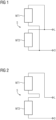
- the generator has a winding from which the FIGS 1 and 2 A section is shown schematically.
- a generator typically has a three-phase stator winding system. This three-phase winding system is mentioned in the FIGS 1 and 2 only the winding for a single phase is shown.
- the winding is divided into a first winding section WT1 and a second winding section WT2.
- the two winding sections WT1 and WT2 are connected in parallel by a switching device S.
- the winding shown for one phase has two parallel winding branches, namely one with the winding section WT1 and one with the winding section WT2.
- the winding has the connections L and O.
- the switching device S or the winding sections WT1 and WT2 are located in FIG 1 in one operating state (parallel connection). This means that the winding sections WT1 and WT2 are connected in parallel during normal generator operation.
- the total current of the winding is divided between the first winding section WT1 and the second winding section WT2.
- the two winding sections WT1 and WT2 for blade assembly are designed according to FIG 2 connected in series. This can be achieved by switching the switching device S.
- the switching device S or the winding sections WT1 and WT2 are connected in series. Therefore, the entire current of the winding flows through both winding sections WT1 and WT2. However, this doubles the torque compared to the case of the winding sections connected in parallel, assuming the same current is applied.
- the stator winding of the generator is designed with a switching device so that a lower current is required for a given torque.
- the winding for one phase has two branches or winding sections.
- a winding can also have more than two winding sections, namely three, four, five, six, etc. branches or winding sections. These can then be switched by a suitably designed switching device. In the operating state, all are connected in parallel and in the blade-mounted state, they are connected in series. If necessary, individual winding sections of the entire winding can be switched in pairs or groups from a parallel connection to a series connection using an appropriately designed switching device.
- the winding can have four winding branches in the operating state (generator operation), while in the blade-mounted state (i.e., motor operation) it has only two or one winding branch between terminals 0 and L.
- the entire winding system of a multi-phase wind turbine generator then has a winding of the type shown above for each phase.
- the winding parts are connected synchronously for all phases in parallel or in series.
- the problem of current reduction is circumvented by switching between series and parallel connection. This allows the full rated torque or, depending on the switching, even a higher torque to be available for installation.
Landscapes
- Engineering & Computer Science (AREA)
- Life Sciences & Earth Sciences (AREA)
- Sustainable Development (AREA)
- Sustainable Energy (AREA)
- Chemical & Material Sciences (AREA)
- Combustion & Propulsion (AREA)
- Mechanical Engineering (AREA)
- General Engineering & Computer Science (AREA)
- Power Engineering (AREA)
- Control Of Eletrric Generators (AREA)
Description
- Die vorliegende Erfindung betrifft ein Verfahren zum Montieren oder Demontieren eines Blattes an einen/von einem Windkraftgenerator, der eine Wicklung aufweist, welche einer Phase eines zu erzeugenden Stroms zugeordnet ist. Unter einem "Blatt" wird hier ein Flügel bzw. ein Rotorblatt einer Windkraftanlage verstanden.
- Bei der Montage von Windkraftanlagen können die in der Regel drei Flügel entweder komplett (einschließlich Nabe) oder einzeln montiert werden. Die Einzelblattmontage macht es notwendig, dass in Zwischenschritten die Nabe mit erst einem oder zwei angebauten Flügeln in eine bestimmte Lage gedreht werden muss. Dies erfordert ein relativ großes Drehmoment, für dessen Aufbringung der Generator verwendet werden kann. Hierfür ist er im motorischen Betrieb einzusetzen. Dazu muss der speisende Umrichter einen Strom sehr kleiner Frequenz liefern, da die Vorschubgeschwindigkeit sehr klein ist.
- Marktübliche Umrichter (z.B. sogenannte Puls-U-Umrichter) haben den Nachteil, dass bei sehr kleinen Frequenzen eine Stromreduktion auf z.B. 50 bis 70 Prozent gegenüber dem Bemessungspunkt erfolgen muss, da der Strom für derart kleine Frequenzen sonst für die Halbleiterbauelemente zu hoch wäre. In der Folge reicht das vom Generator abgebbare Drehmoment möglicherweise für die Drehung der Nabe nicht aus.
- Bislang wurden für die Blattmontage häufig hydraulische Antriebe eingesetzt, die das notwendige Drehmoment aufbringen können. Es wurden für die Blattmontage aber auch elektrische Antriebe verwendet, wobei die Einschränkungen des Umrichters, also die Stromreduktion, in Kauf genommen wurde.
- Die
AT 408 497 B - Die
DE 10 2007 049 368 A1 beschreibt ein Verfahren zur Errichtung einer Windkraftanlage, bei welchem die Nabe ohne Rotorblätter montiert wird, und jedes Rotorblatt in 6 Uhr Stellung mittels Seilzugtechnik montiert wird, wobei nach Anbau eines Rotorblattes der Generator mittels dem generatorseitigen Wechselrichter zur Montage weiterer Blätter als Motor betrieben wird. - Die Aufgabe der vorliegenden Erfindung besteht somit darin, den apparativen Aufwand für die Montage bzw. Demontage von Blättern einer Windkraftanlage zu verringem.
- Diese Aufgabe wird gelöst durch ein Verfahren nach Anspruch 1.
- Ein nicht beanspruchtes Ausführungsbeispiel betrifft einen Windkraftgenerator mit einer Wicklung, die einer Phase eines zu erzeugenden Stroms zugeordnet ist, wobei die Wicklung in ein erstes und ein zweites Wicklungsteil unterteilt ist, und eine Schalteinrichtung an die Wicklung angeschlossen ist, mit der das erste Wicklungsteil und das zweite Wicklungsteil in einem Betriebszustand zueinander parallel und in einem Blattmontagezustand miteinander in Serie schaltbar sind. Darüber hinaus weist der Windkraftgenerator einen Umrichter auf, von dem die Wicklung ansteuerbar ist. Dies bedeutet, dass der Umrichter bidirektional ausgelegt sein muss, da er im Generatorbetrieb den Strom von den Spulen aufnimmt, während er im motorischen Betrieb Strom für die Wicklung liefert, um die Nabe des Windkraftgenerators für die Blattmontage entsprechend weiter zu drehen. Weiterhin ist erfindungsgemäß von dem Umrichter für die Wicklung ein Strom mit einer Frequenz von unter 10 Hz und insbesondere unter 1 Hz lieferbar. Damit können die geringen Drehzahlen realisiert werden, die für die Blattmontage notwendig sind. Dabei wird unter einer Schalteinrichtung eine Einrichtung verstanden, bei der eine Parallelschaltung der Wicklungsteile in eine Serienschaltung manuell umklemmbar ist. Die Schalteinrichtung stellt einen Klemmenkasten dar.
- Erfindungsgemäß wird bereitgestellt ein Verfahren zum Montieren oder Demontieren eines Blattes an einen/von einem Windkraftgenerator, der eine Wicklung aufweist, welche einer Phase eines zu erzeugenden Stroms zugeordnet ist, und eine Schalteinrichtung aufweist, welche als Klemmenkasten ausgebildet ist, wobei die Wicklung unterteilt in ein erstes und ein zweites Wicklungsteil bereitgestellt wird, das erste Wicklungsteil und das zweite Wicklungsteil von einem Betriebszustand, in dem sie zueinander parallel geschaltet sind, in einen Blattmontagezustand geschaltet werden, in dem sie miteinander in Serie geschaltet sind, indem eine Parallelschaltung der Wicklungsteile in eine Serienschaltung manuell umgeklemmt wird, der Windkraftgenerator in dem Blattmontagezustand der Wicklungsteile motorisch betrieben wird, und das Blatt an den Generator montiert oder von ihm demontiert wird. Weiterhin weist der Windkraftgenerator einen Umrichter auf, von dem die Wicklung ansteuerbar ist, wobei von dem Umrichter im Blattmontagezustand für die Wicklung ein Strom mit einer Frequenz von unter 10 HZ geliefert wird.
- In erfindungsgemäßer Weise wird der Windkraftgenerator im Betriebszustand und im Blattmontagezustand also in zwei verschiedenen Modi betrieben. Dazu ist es notwendig, dass die Wicklung des Windkraftgenerators zumindest zweigeteilt ist. Während des generatorischen Betriebs, also in dem Betriebszustand, werden die Teile der Wicklung parallel geschaltet. Für den exemplarischen Fall von zwei gleichen Wicklungsteilen wird dadurch der Strom durch die Wicklungsteile halbiert gegenüber dem Fall, dass die Wicklungsteile in Serie geschaltet sind. Für die Blattmontage können die Wicklungsteile dann aber in Serie geschaltet werden, sodass der Strom dann ungeteilt durch beide Wicklungsteile fließt und dadurch ein hohes Drehmoment erzielt werden kann, da dieses proportional zum Produkt von Stromstärke und Wicklungszahl ist.
- Gegebenenfalls ist das erste Wicklungsteil in mindestens ein drittes und viertes Wicklungsteil unterteilt, wobei das zweite sowie das mindestens dritte und vierte Wicklungsteil in dem Betriebszustand zueinander jeweils parallel und in dem Blattmontagezustand miteinander in Serie geschaltet sind. Dies bedeutet, dass die Wicklung nicht nur zwei, sondern auch mehr Wicklungsteile aufweisen kann. Im Betriebszustand sind dann all diese Teile einzeln zueinander parallel geschaltet, während sie für die Blattmontage paarweise, gruppenweise oder alle zusammen in Serie geschaltet werden können. Dabei müssen die einzelnen Wicklungsteile auch nicht alle gleich groß sein, vorzugsweise sind sie es aber.
- Darüber hinaus kann der Windkraftgenerator für mindestens zwei Phasen ausgelegt sein, wobei für jede der Phasen jeweils eine Wicklung und eine Schalteinrichtung der genannten Art vorgesehen ist. Dies bedeutet, dass für jede Phase (z.B. drei Phasen oder sechs Phasen) jeweils eine separate Wicklung vorhanden ist. Jede dieser separaten Wicklungen ist dann wieder in zwei oder mehr Wicklungsteile unterteilt. Die Wicklungsteile können dann über entsprechende Schalteinrichtungen, die miteinander eine gemeinsame Schaltvorrichtung bilden, vorzugsweise synchron miteinander parallel oder in Reihe geschaltet werden.
- Wie oben bereits angedeutet wurde, wird vorzugsweise eine Windkraftanlage mit einem derartigen Windkraftgenerator ausgestattet. Dabei ist an dem Windkraftgenerator drehbar eine Nabe montiert, an welcher wiederum radial die Blätter bzw. Flügel montiert sind/werden.
- Die vorliegende Erfindung wird nun anhand der beigefügten Zeichnungen näher erläutert, in denen zeigen:
- FIG 1
- eine Parallelschaltung von Wicklungsteilen für den Betrieb eines Windkraftgenerators und
- FIG 2
- eine Serienschaltung von Wicklungsteilen für die Blattmontage des Windkraftgenerators.
- Die nachfolgend näher geschilderten Ausführungsbeispiele stellen bevorzugte Ausführungsformen des erfindungsgemäßen Verfahrens der vorliegenden Erfindung dar.
- Eine Windkraftanlageweist einen Rotor auf, der auf einem Turm drehbeweglich gelagert ist. Der Rotor treibt direkt oder indirekt über ein Getriebe einen Generator (hier Windkraftgenerator) an. Dieser produziert elektrische Energie, die in ein Netz eingespeist werden kann.
- Der Rotor weist in der Regel drei Rotorblätter auf, aber es ist auch eine andere Anzahl an Rotorblättern möglich. Im Zentrum des Rotors befindet sich eine Nabe an der die Rotorblätter (hier auch als Blätter oder Flügel bezeichnet) befestigt werden.
- Die Montage des Rotors erfolgt häufig an der Spitze des Turms der Windkraftanlage. Dabei wird ein Rotorblatt beispielsweise in horizontaler Lage an die Nabe angeschraubt. Wurde bereits eines oder mehrere Rotorblätter an der Nabe befestigt, so ist ein entsprechend hohes Drehmoment aufzubringen, um die Nabe in die gewünschte Lage zu drehen. Dazu wird der Windkraftgenerator mit einer sehr geringen Frequenz motorisch betrieben, um die Nabe langsam in die gewünschte Position zu drehen.
- Der Generator besitzt eine Wicklung, von der in den
FIG 1 und 2 ein Ausschnitt schematisch dargestellt ist. Ein Generator besitzt typischerweise ein dreiphasiges Ständerwicklungssystem. Von diesem dreiphasigen Wicklungssystem ist in denFIG 1 und 2 jeweils lediglich die Wicklung für eine einzige Phase dargestellt. Die Wicklung ist aufgeteilt in einem ersten Wicklungsteil WT1 und einen zweiten Wicklungsteil WT2. Die beiden Wicklungsteile WT1 und WT2 sind durch eine Schalteinrichtung S parallel geschaltet. Damit besitzt die dargestellte Wicklung für die eine Phase zwei parallele Wicklungszweige, nämlich einen mit dem Wicklungsteil WT1 und einen mit dem Wicklungsteil WT2. Die Wicklung besitzt die Anschlüsse L und 0. Die Schalteinrichtung S bzw. die Wicklungsteile WT1 und WT2 befinden sich inFIG 1 in einem Betriebszustand (Parallelschaltung). Dies bedeutet, dass die Wicklungsteile WT1 und WT2 während des üblichen Generatorbetriebs parallel geschaltet sind. Der Gesamtstrom der Wicklung teilt sich dabei auf den ersten Wicklungsteil WT1 und den zweiten Wicklungsteil WT2 auf. - Für die Blattmontage ist ein sehr hohes Drehmoment des motorisch betriebenen Generators notwendig. Das Drehmoment ist proportional zum Produkt von Strom und Windungszahl. Daher werden die beiden Wicklungsteile WT1 und WT2 für die Blattmontage gemäß
FIG 2 in Serie geschaltet. Dies lässt sich durch ein Umschalten der Schalteinrichtung S erreichen. In dem inFIG 2 dargestellten Blattmontagezustand der Schalteinrichtung S bzw. der Wicklungsteile WT1 und WT2 sind diese also in Serie geschaltet. Daher fließt der gesamte Strom der Wicklung durch beide Wicklungsteile WT1 und WT2. Damit verdoppelt sich jedoch das Drehmoment gegenüber dem Fall der parallel geschalteten Wicklungsteile, wenn die Einprägung des gleichen Stroms vorausgesetzt wird. - Die Ständerwicklung des Generators wird mit einer Umschaltmöglichkeit (Schalteinrichtung) derart ausgeführt, dass für ein gegebenes Drehmoment ein geringerer Strom benötigt wird.
- In dem Beispiel der
FIG 1 und 2 ist dargelegt, dass die Wicklung für eine Phase zwei Zweige bzw. Wicklungsteile aufweist. Eine Wicklung kann aber auch mehr als zwei Wicklungsteile, nämlich drei, vier, fünf, sechs etc. Zweige bzw. Wicklungsteile aufweisen. Diese können dann durch eine entsprechend ausgebildete Schalteinrichtung im Betriebszustand alle parallel zueinander und im Blattmontagezustand in Serie miteinander geschaltet sein. Gegebenenfalls können einzelne Wicklungsteile der gesamten Wicklung paarweise oder gruppenweise von einer Parallelschaltung in eine Serienschaltung durch eine entsprechend ausgelegte Schalteinrichtung schaltbar sein. In einem konkreten Beispiel kann die Wicklung im Betriebszustand (Generatorbetrieb) vier Wicklungszweige aufweisen, während sie im Blattmontagezustand (d.h. motorischer Betrieb) nur zwei oder einen Wicklungszweig zwischen den Anschlüssen 0 und L aufweist. - Das gesamte Wicklungssystem eines mehrphasigen Windkraftgenerators besitzt dann für jede Phase jeweils eine Wicklung der oben dargestellten Art. Die Wicklungsteile werden synchron für alle Phasen parallel bzw. in Serie geschaltet
- Erfindungsgemäß wird durch das Umschalten zwischen Serien- und Parallelschaltung das Problem der Stromreduktion umgangen. Damit steht das volle Bemessungsmoment oder, je nach Umschaltung, sogar ein höheres Moment zur Montage zur Verfügung.
Claims (1)
- Verfahren zum Montieren oder Demontieren eines Blattes an einen/von einem Windkraftgenerator, der eine Wicklung aufweist, welche einer Phase eines zu erzeugenden Stroms zugeordnet ist, und eine Schalteinrichtung (S) aufweist, welche als Klemmenkasten ausgebildet ist,
dadurch gekennzeichnet, dass- die Wicklung unterteilt in ein erstes (WT1) und ein zweites Wicklungsteil (WT2) bereitgestellt wird,- das erste Wicklungsteil (WT1) und das zweite Wicklungsteil von einem Betriebszustand, in dem sie zueinander parallel geschaltet sind, in einen Blattmontagezustand geschaltet werden, in dem sie miteinander in Serie geschaltet sind, indem eine Parallelschaltung der Wicklungsteile (WT1, WT2) in eine Serienschaltung über die Schalteinrichtung (S) manuell umgeklemmt wird,- der Windkraftgenerator in dem Blattmontagezustand der Wicklungsteile motorisch betrieben wird,- das Blatt an den Generator montiert oder von ihm demontiert wird, und- der Windkraftgenerator einen Umrichter aufweist, von dem die Wicklung ansteuerbar ist, wobei von dem Umrichter im Blattmontagezustand für die Wicklung ein Strom mit einer Frequenz von unter 10 Hz geliefert wird.
Applications Claiming Priority (2)
| Application Number | Priority Date | Filing Date | Title |
|---|---|---|---|
| DE102012201762A DE102012201762A1 (de) | 2012-02-07 | 2012-02-07 | Windkraftgenerator und Blattmontageverfahren |
| PCT/EP2013/051000 WO2013117411A2 (de) | 2012-02-07 | 2013-01-21 | Windkraftgenerator und blattmontageverfahren |
Publications (3)
| Publication Number | Publication Date |
|---|---|
| EP2800898A2 EP2800898A2 (de) | 2014-11-12 |
| EP2800898B1 EP2800898B1 (de) | 2019-12-11 |
| EP2800898B2 true EP2800898B2 (de) | 2025-04-02 |
Family
ID=47632999
Family Applications (1)
| Application Number | Title | Priority Date | Filing Date |
|---|---|---|---|
| EP13702373.5A Active EP2800898B2 (de) | 2012-02-07 | 2013-01-21 | Blattmontageverfahren für einen windkraftgenerator |
Country Status (3)
| Country | Link |
|---|---|
| EP (1) | EP2800898B2 (de) |
| DE (1) | DE102012201762A1 (de) |
| WO (1) | WO2013117411A2 (de) |
Families Citing this family (2)
| Publication number | Priority date | Publication date | Assignee | Title |
|---|---|---|---|---|
| DE102012201762A1 (de) | 2012-02-07 | 2013-08-08 | Siemens Aktiengesellschaft | Windkraftgenerator und Blattmontageverfahren |
| EP4163492A1 (de) | 2021-10-08 | 2023-04-12 | General Electric Renovables España S.L. | Windturbinengeneratoren und verfahren zum drehen einer nabe einer windturbine |
Citations (1)
| Publication number | Priority date | Publication date | Assignee | Title |
|---|---|---|---|---|
| US20110241630A1 (en) † | 2008-09-03 | 2011-10-06 | Exro Technologies Inc. | Power conversion system for a multi-stage generator |
Family Cites Families (5)
| Publication number | Priority date | Publication date | Assignee | Title |
|---|---|---|---|---|
| AT408497B (de) * | 1998-11-03 | 2001-12-27 | Johann W Kolar | Vorrichtung zur serien-parallel-umschaltung der umrichtergespeisten teilwicklungssysteme einer drehstrommaschine und verbindung der umrichterausgänge mit einem spannungseinprägenden speicher |
| DE102007049368A1 (de) * | 2006-11-19 | 2008-05-21 | Setec Gmbh | Windenergieanlage mit erhöhter Betriebssicherheit |
| US7948100B2 (en) | 2007-12-19 | 2011-05-24 | General Electric Company | Braking and positioning system for a wind turbine rotor |
| CN203670098U (zh) * | 2011-02-16 | 2014-06-25 | 株式会社安川电机 | 风力发电用电力转换装置、风力发电装置以及风场 |
| DE102012201762A1 (de) | 2012-02-07 | 2013-08-08 | Siemens Aktiengesellschaft | Windkraftgenerator und Blattmontageverfahren |
-
2012
- 2012-02-07 DE DE102012201762A patent/DE102012201762A1/de not_active Withdrawn
-
2013
- 2013-01-21 EP EP13702373.5A patent/EP2800898B2/de active Active
- 2013-01-21 WO PCT/EP2013/051000 patent/WO2013117411A2/de not_active Ceased
Patent Citations (1)
| Publication number | Priority date | Publication date | Assignee | Title |
|---|---|---|---|---|
| US20110241630A1 (en) † | 2008-09-03 | 2011-10-06 | Exro Technologies Inc. | Power conversion system for a multi-stage generator |
Also Published As
| Publication number | Publication date |
|---|---|
| WO2013117411A3 (de) | 2014-07-24 |
| EP2800898B1 (de) | 2019-12-11 |
| WO2013117411A2 (de) | 2013-08-15 |
| EP2800898A2 (de) | 2014-11-12 |
| DE102012201762A1 (de) | 2013-08-08 |
Similar Documents
| Publication | Publication Date | Title |
|---|---|---|
| EP2981709B1 (de) | Verfahren zum arretieren einer windturbine und windturbine zur durchführung des verfahrens | |
| WO2014033073A1 (de) | Windpark mit gleichspannungsnetz | |
| WO2010149439A2 (de) | Vorrichtung zur versorgung eines elektrischen antriebes für ein kraftfahrzeug | |
| DE102008043626A1 (de) | Leistungsverteilungs-Vorrichtung zum Verteilen von Leistung und Verfahren zum Verteilen von Leistung | |
| WO2023110012A1 (de) | Elektrischer antrieb eines fahrzeuges | |
| DE102017115513B3 (de) | Vorrichtung und Verfahren zum Überprüfen des elektro-dynamischen Verhaltens eines Antriebsstrangs einer Stromerzeugungseinrichtung am Netz | |
| EP3649343B1 (de) | Mobile steuereinheit für eine windenergieanlage | |
| EP2800898B2 (de) | Blattmontageverfahren für einen windkraftgenerator | |
| WO2003025390A1 (de) | Windparkanlage | |
| WO2011006809A2 (de) | Segmentierter ständer für eine dynamoelektrische maschine | |
| EP3547505A1 (de) | Kombination einer elektrischen drehstrommaschine mit einer umrichtereinheit und windkraftanlage | |
| EP2771663B1 (de) | Prüfvorrichtung und verfahren zum prüfen einer ersten und/oder einer zweiten elektrischen maschine | |
| DE102010062060A1 (de) | Drehstrom-Asynchronmaschine und Verfahren zum Betreiben einer Drehstrom-Asynchronmaschine in einem Luft- oder Raumfahrzeug | |
| EP2117108B1 (de) | Verfahren zum Starten eines Systems zur Erzeugung von elektrischer Energie | |
| EP3765736B1 (de) | Windkraftanlagenblattverstellsystem | |
| DE102020203945A1 (de) | Statorwicklungssystem mit serieller Spulenwicklung | |
| EP1426616B1 (de) | Netzkopplung einer Windkraftanlage | |
| EP2730780A1 (de) | Windkraftanlage mit einer elektrischen Bremseinrichtung | |
| EP3984124A1 (de) | Dual purpose converter | |
| DE102011008061A1 (de) | Drehzahlstabilisierung einer Windkraftanlage | |
| DE102011001513A1 (de) | Verfahren zur Steuerung oder Regelung einer rotierenden elektrischen Maschine und rotierende elektrische Maschine | |
| EP3280911B1 (de) | Verstelleinrichtung zum verstellen eines rotorblattes einer windenergieanlage | |
| EP4287468A1 (de) | Elektromotorsystem | |
| DE102021133266A1 (de) | Anordnung zur Strom- bzw. Spannungsversorgung eines elektrischen Antriebes | |
| DE102012208946A1 (de) | Vorrichtung und Verfahren zum Anfahren eines Generators |
Legal Events
| Date | Code | Title | Description |
|---|---|---|---|
| PUAI | Public reference made under article 153(3) epc to a published international application that has entered the european phase |
Free format text: ORIGINAL CODE: 0009012 |
|
| 17P | Request for examination filed |
Effective date: 20140805 |
|
| AK | Designated contracting states |
Kind code of ref document: A2 Designated state(s): AL AT BE BG CH CY CZ DE DK EE ES FI FR GB GR HR HU IE IS IT LI LT LU LV MC MK MT NL NO PL PT RO RS SE SI SK SM TR |
|
| DAX | Request for extension of the european patent (deleted) | ||
| RAP1 | Party data changed (applicant data changed or rights of an application transferred) |
Owner name: SIEMENS AKTIENGESELLSCHAFT |
|
| STAA | Information on the status of an ep patent application or granted ep patent |
Free format text: STATUS: EXAMINATION IS IN PROGRESS |
|
| 17Q | First examination report despatched |
Effective date: 20180416 |
|
| REG | Reference to a national code |
Ref country code: DE Ref legal event code: R079 Ref document number: 502013014052 Country of ref document: DE Free format text: PREVIOUS MAIN CLASS: F03D0001000000 Ipc: F03D0001060000 |
|
| RIC1 | Information provided on ipc code assigned before grant |
Ipc: F03D 1/06 20060101AFI20190621BHEP Ipc: H02K 3/28 20060101ALI20190621BHEP Ipc: F03D 13/10 20160101ALI20190621BHEP Ipc: F03D 1/00 20060101ALI20190621BHEP Ipc: H02K 7/18 20060101ALI20190621BHEP |
|
| GRAP | Despatch of communication of intention to grant a patent |
Free format text: ORIGINAL CODE: EPIDOSNIGR1 |
|
| STAA | Information on the status of an ep patent application or granted ep patent |
Free format text: STATUS: GRANT OF PATENT IS INTENDED |
|
| INTG | Intention to grant announced |
Effective date: 20190806 |
|
| GRAS | Grant fee paid |
Free format text: ORIGINAL CODE: EPIDOSNIGR3 |
|
| GRAA | (expected) grant |
Free format text: ORIGINAL CODE: 0009210 |
|
| STAA | Information on the status of an ep patent application or granted ep patent |
Free format text: STATUS: THE PATENT HAS BEEN GRANTED |
|
| AK | Designated contracting states |
Kind code of ref document: B1 Designated state(s): AL AT BE BG CH CY CZ DE DK EE ES FI FR GB GR HR HU IE IS IT LI LT LU LV MC MK MT NL NO PL PT RO RS SE SI SK SM TR |
|
| REG | Reference to a national code |
Ref country code: GB Ref legal event code: FG4D Free format text: NOT ENGLISH |
|
| REG | Reference to a national code |
Ref country code: CH Ref legal event code: EP |
|
| REG | Reference to a national code |
Ref country code: AT Ref legal event code: REF Ref document number: 1212446 Country of ref document: AT Kind code of ref document: T Effective date: 20191215 |
|
| REG | Reference to a national code |
Ref country code: DE Ref legal event code: R096 Ref document number: 502013014052 Country of ref document: DE |
|
| REG | Reference to a national code |
Ref country code: IE Ref legal event code: FG4D Free format text: LANGUAGE OF EP DOCUMENT: GERMAN |
|
| REG | Reference to a national code |
Ref country code: NL Ref legal event code: MP Effective date: 20191211 |
|
| REG | Reference to a national code |
Ref country code: LT Ref legal event code: MG4D |
|
| PG25 | Lapsed in a contracting state [announced via postgrant information from national office to epo] |
Ref country code: ES Free format text: LAPSE BECAUSE OF FAILURE TO SUBMIT A TRANSLATION OF THE DESCRIPTION OR TO PAY THE FEE WITHIN THE PRESCRIBED TIME-LIMIT Effective date: 20191211 Ref country code: FI Free format text: LAPSE BECAUSE OF FAILURE TO SUBMIT A TRANSLATION OF THE DESCRIPTION OR TO PAY THE FEE WITHIN THE PRESCRIBED TIME-LIMIT Effective date: 20191211 Ref country code: BG Free format text: LAPSE BECAUSE OF FAILURE TO SUBMIT A TRANSLATION OF THE DESCRIPTION OR TO PAY THE FEE WITHIN THE PRESCRIBED TIME-LIMIT Effective date: 20200311 Ref country code: LT Free format text: LAPSE BECAUSE OF FAILURE TO SUBMIT A TRANSLATION OF THE DESCRIPTION OR TO PAY THE FEE WITHIN THE PRESCRIBED TIME-LIMIT Effective date: 20191211 Ref country code: NO Free format text: LAPSE BECAUSE OF FAILURE TO SUBMIT A TRANSLATION OF THE DESCRIPTION OR TO PAY THE FEE WITHIN THE PRESCRIBED TIME-LIMIT Effective date: 20200311 Ref country code: GR Free format text: LAPSE BECAUSE OF FAILURE TO SUBMIT A TRANSLATION OF THE DESCRIPTION OR TO PAY THE FEE WITHIN THE PRESCRIBED TIME-LIMIT Effective date: 20200312 Ref country code: SE Free format text: LAPSE BECAUSE OF FAILURE TO SUBMIT A TRANSLATION OF THE DESCRIPTION OR TO PAY THE FEE WITHIN THE PRESCRIBED TIME-LIMIT Effective date: 20191211 Ref country code: LV Free format text: LAPSE BECAUSE OF FAILURE TO SUBMIT A TRANSLATION OF THE DESCRIPTION OR TO PAY THE FEE WITHIN THE PRESCRIBED TIME-LIMIT Effective date: 20191211 |
|
| PG25 | Lapsed in a contracting state [announced via postgrant information from national office to epo] |
Ref country code: RS Free format text: LAPSE BECAUSE OF FAILURE TO SUBMIT A TRANSLATION OF THE DESCRIPTION OR TO PAY THE FEE WITHIN THE PRESCRIBED TIME-LIMIT Effective date: 20191211 Ref country code: HR Free format text: LAPSE BECAUSE OF FAILURE TO SUBMIT A TRANSLATION OF THE DESCRIPTION OR TO PAY THE FEE WITHIN THE PRESCRIBED TIME-LIMIT Effective date: 20191211 |
|
| PG25 | Lapsed in a contracting state [announced via postgrant information from national office to epo] |
Ref country code: AL Free format text: LAPSE BECAUSE OF FAILURE TO SUBMIT A TRANSLATION OF THE DESCRIPTION OR TO PAY THE FEE WITHIN THE PRESCRIBED TIME-LIMIT Effective date: 20191211 |
|
| PG25 | Lapsed in a contracting state [announced via postgrant information from national office to epo] |
Ref country code: CZ Free format text: LAPSE BECAUSE OF FAILURE TO SUBMIT A TRANSLATION OF THE DESCRIPTION OR TO PAY THE FEE WITHIN THE PRESCRIBED TIME-LIMIT Effective date: 20191211 Ref country code: RO Free format text: LAPSE BECAUSE OF FAILURE TO SUBMIT A TRANSLATION OF THE DESCRIPTION OR TO PAY THE FEE WITHIN THE PRESCRIBED TIME-LIMIT Effective date: 20191211 Ref country code: NL Free format text: LAPSE BECAUSE OF FAILURE TO SUBMIT A TRANSLATION OF THE DESCRIPTION OR TO PAY THE FEE WITHIN THE PRESCRIBED TIME-LIMIT Effective date: 20191211 Ref country code: EE Free format text: LAPSE BECAUSE OF FAILURE TO SUBMIT A TRANSLATION OF THE DESCRIPTION OR TO PAY THE FEE WITHIN THE PRESCRIBED TIME-LIMIT Effective date: 20191211 Ref country code: PT Free format text: LAPSE BECAUSE OF FAILURE TO SUBMIT A TRANSLATION OF THE DESCRIPTION OR TO PAY THE FEE WITHIN THE PRESCRIBED TIME-LIMIT Effective date: 20200506 |
|
| PG25 | Lapsed in a contracting state [announced via postgrant information from national office to epo] |
Ref country code: IS Free format text: LAPSE BECAUSE OF FAILURE TO SUBMIT A TRANSLATION OF THE DESCRIPTION OR TO PAY THE FEE WITHIN THE PRESCRIBED TIME-LIMIT Effective date: 20200411 Ref country code: SK Free format text: LAPSE BECAUSE OF FAILURE TO SUBMIT A TRANSLATION OF THE DESCRIPTION OR TO PAY THE FEE WITHIN THE PRESCRIBED TIME-LIMIT Effective date: 20191211 Ref country code: SM Free format text: LAPSE BECAUSE OF FAILURE TO SUBMIT A TRANSLATION OF THE DESCRIPTION OR TO PAY THE FEE WITHIN THE PRESCRIBED TIME-LIMIT Effective date: 20191211 |
|
| REG | Reference to a national code |
Ref country code: CH Ref legal event code: PL |
|
| REG | Reference to a national code |
Ref country code: DE Ref legal event code: R026 Ref document number: 502013014052 Country of ref document: DE |
|
| PLBI | Opposition filed |
Free format text: ORIGINAL CODE: 0009260 |
|
| PLAX | Notice of opposition and request to file observation + time limit sent |
Free format text: ORIGINAL CODE: EPIDOSNOBS2 |
|
| PG25 | Lapsed in a contracting state [announced via postgrant information from national office to epo] |
Ref country code: MC Free format text: LAPSE BECAUSE OF FAILURE TO SUBMIT A TRANSLATION OF THE DESCRIPTION OR TO PAY THE FEE WITHIN THE PRESCRIBED TIME-LIMIT Effective date: 20191211 |
|
| REG | Reference to a national code |
Ref country code: BE Ref legal event code: MM Effective date: 20200131 |
|
| 26 | Opposition filed |
Opponent name: GE WIND ENERGY GMBH Effective date: 20200911 |
|
| PG25 | Lapsed in a contracting state [announced via postgrant information from national office to epo] |
Ref country code: LU Free format text: LAPSE BECAUSE OF NON-PAYMENT OF DUE FEES Effective date: 20200121 Ref country code: DK Free format text: LAPSE BECAUSE OF FAILURE TO SUBMIT A TRANSLATION OF THE DESCRIPTION OR TO PAY THE FEE WITHIN THE PRESCRIBED TIME-LIMIT Effective date: 20191211 |
|
| REG | Reference to a national code |
Ref country code: DE Ref legal event code: R081 Ref document number: 502013014052 Country of ref document: DE Owner name: FLENDER GMBH, DE Free format text: FORMER OWNER: SIEMENS AKTIENGESELLSCHAFT, 80333 MUENCHEN, DE |
|
| PG25 | Lapsed in a contracting state [announced via postgrant information from national office to epo] |
Ref country code: LI Free format text: LAPSE BECAUSE OF NON-PAYMENT OF DUE FEES Effective date: 20200131 Ref country code: SI Free format text: LAPSE BECAUSE OF FAILURE TO SUBMIT A TRANSLATION OF THE DESCRIPTION OR TO PAY THE FEE WITHIN THE PRESCRIBED TIME-LIMIT Effective date: 20191211 Ref country code: CH Free format text: LAPSE BECAUSE OF NON-PAYMENT OF DUE FEES Effective date: 20200131 Ref country code: PL Free format text: LAPSE BECAUSE OF FAILURE TO SUBMIT A TRANSLATION OF THE DESCRIPTION OR TO PAY THE FEE WITHIN THE PRESCRIBED TIME-LIMIT Effective date: 20191211 Ref country code: BE Free format text: LAPSE BECAUSE OF NON-PAYMENT OF DUE FEES Effective date: 20200131 |
|
| RAP2 | Party data changed (patent owner data changed or rights of a patent transferred) |
Owner name: FLENDER GMBH |
|
| REG | Reference to a national code |
Ref country code: GB Ref legal event code: 732E Free format text: REGISTERED BETWEEN 20201210 AND 20201216 |
|
| PLBB | Reply of patent proprietor to notice(s) of opposition received |
Free format text: ORIGINAL CODE: EPIDOSNOBS3 |
|
| PG25 | Lapsed in a contracting state [announced via postgrant information from national office to epo] |
Ref country code: IE Free format text: LAPSE BECAUSE OF NON-PAYMENT OF DUE FEES Effective date: 20200121 Ref country code: FR Free format text: LAPSE BECAUSE OF NON-PAYMENT OF DUE FEES Effective date: 20200211 Ref country code: IT Free format text: LAPSE BECAUSE OF FAILURE TO SUBMIT A TRANSLATION OF THE DESCRIPTION OR TO PAY THE FEE WITHIN THE PRESCRIBED TIME-LIMIT Effective date: 20191211 |
|
| REG | Reference to a national code |
Ref country code: AT Ref legal event code: MM01 Ref document number: 1212446 Country of ref document: AT Kind code of ref document: T Effective date: 20200121 |
|
| REG | Reference to a national code |
Ref country code: DE Ref legal event code: R082 Ref document number: 502013014052 Country of ref document: DE Representative=s name: MICHALSKI HUETTERMANN & PARTNER PATENTANWAELTE, DE |
|
| PG25 | Lapsed in a contracting state [announced via postgrant information from national office to epo] |
Ref country code: AT Free format text: LAPSE BECAUSE OF NON-PAYMENT OF DUE FEES Effective date: 20200121 |
|
| PG25 | Lapsed in a contracting state [announced via postgrant information from national office to epo] |
Ref country code: TR Free format text: LAPSE BECAUSE OF FAILURE TO SUBMIT A TRANSLATION OF THE DESCRIPTION OR TO PAY THE FEE WITHIN THE PRESCRIBED TIME-LIMIT Effective date: 20191211 Ref country code: MT Free format text: LAPSE BECAUSE OF FAILURE TO SUBMIT A TRANSLATION OF THE DESCRIPTION OR TO PAY THE FEE WITHIN THE PRESCRIBED TIME-LIMIT Effective date: 20191211 Ref country code: CY Free format text: LAPSE BECAUSE OF FAILURE TO SUBMIT A TRANSLATION OF THE DESCRIPTION OR TO PAY THE FEE WITHIN THE PRESCRIBED TIME-LIMIT Effective date: 20191211 |
|
| PG25 | Lapsed in a contracting state [announced via postgrant information from national office to epo] |
Ref country code: MK Free format text: LAPSE BECAUSE OF FAILURE TO SUBMIT A TRANSLATION OF THE DESCRIPTION OR TO PAY THE FEE WITHIN THE PRESCRIBED TIME-LIMIT Effective date: 20191211 |
|
| APAH | Appeal reference modified |
Free format text: ORIGINAL CODE: EPIDOSCREFNO |
|
| APBM | Appeal reference recorded |
Free format text: ORIGINAL CODE: EPIDOSNREFNO |
|
| APBP | Date of receipt of notice of appeal recorded |
Free format text: ORIGINAL CODE: EPIDOSNNOA2O |
|
| APBQ | Date of receipt of statement of grounds of appeal recorded |
Free format text: ORIGINAL CODE: EPIDOSNNOA3O |
|
| APBU | Appeal procedure closed |
Free format text: ORIGINAL CODE: EPIDOSNNOA9O |
|
| PUAH | Patent maintained in amended form |
Free format text: ORIGINAL CODE: 0009272 |
|
| REG | Reference to a national code |
Ref country code: CH Ref legal event code: PK Free format text: TITEL |
|
| STAA | Information on the status of an ep patent application or granted ep patent |
Free format text: STATUS: PATENT MAINTAINED AS AMENDED |
|
| 27A | Patent maintained in amended form |
Effective date: 20250402 |
|
| AK | Designated contracting states |
Kind code of ref document: B2 Designated state(s): AL AT BE BG CH CY CZ DE DK EE ES FI FR GB GR HR HU IE IS IT LI LT LU LV MC MK MT NL NO PL PT RO RS SE SI SK SM TR |
|
| REG | Reference to a national code |
Ref country code: DE Ref legal event code: R102 Ref document number: 502013014052 Country of ref document: DE |
|
| PGFP | Annual fee paid to national office [announced via postgrant information from national office to epo] |
Ref country code: GB Payment date: 20260123 Year of fee payment: 14 |
|
| PGFP | Annual fee paid to national office [announced via postgrant information from national office to epo] |
Ref country code: DE Payment date: 20260128 Year of fee payment: 14 |