EP2800379A1 - Color imaging element - Google Patents
Color imaging element Download PDFInfo
- Publication number
- EP2800379A1 EP2800379A1 EP12862166.1A EP12862166A EP2800379A1 EP 2800379 A1 EP2800379 A1 EP 2800379A1 EP 12862166 A EP12862166 A EP 12862166A EP 2800379 A1 EP2800379 A1 EP 2800379A1
- Authority
- EP
- European Patent Office
- Prior art keywords
- color
- filters
- array
- pixels
- imaging element
- Prior art date
- Legal status (The legal status is an assumption and is not a legal conclusion. Google has not performed a legal analysis and makes no representation as to the accuracy of the status listed.)
- Withdrawn
Links
Images








Classifications
-
- H—ELECTRICITY
- H04—ELECTRIC COMMUNICATION TECHNIQUE
- H04N—PICTORIAL COMMUNICATION, e.g. TELEVISION
- H04N13/00—Stereoscopic video systems; Multi-view video systems; Details thereof
- H04N13/20—Image signal generators
- H04N13/204—Image signal generators using stereoscopic image cameras
- H04N13/207—Image signal generators using stereoscopic image cameras using a single two-dimensional [2D] image sensor
- H04N13/218—Image signal generators using stereoscopic image cameras using a single two-dimensional [2D] image sensor using spatial multiplexing
-
- H—ELECTRICITY
- H04—ELECTRIC COMMUNICATION TECHNIQUE
- H04N—PICTORIAL COMMUNICATION, e.g. TELEVISION
- H04N13/00—Stereoscopic video systems; Multi-view video systems; Details thereof
- H04N13/20—Image signal generators
- H04N13/257—Colour aspects
-
- H—ELECTRICITY
- H04—ELECTRIC COMMUNICATION TECHNIQUE
- H04N—PICTORIAL COMMUNICATION, e.g. TELEVISION
- H04N23/00—Cameras or camera modules comprising electronic image sensors; Control thereof
- H04N23/10—Cameras or camera modules comprising electronic image sensors; Control thereof for generating image signals from different wavelengths
- H04N23/12—Cameras or camera modules comprising electronic image sensors; Control thereof for generating image signals from different wavelengths with one sensor only
-
- H—ELECTRICITY
- H04—ELECTRIC COMMUNICATION TECHNIQUE
- H04N—PICTORIAL COMMUNICATION, e.g. TELEVISION
- H04N23/00—Cameras or camera modules comprising electronic image sensors; Control thereof
- H04N23/80—Camera processing pipelines; Components thereof
- H04N23/84—Camera processing pipelines; Components thereof for processing colour signals
- H04N23/843—Demosaicing, e.g. interpolating colour pixel values
-
- H—ELECTRICITY
- H04—ELECTRIC COMMUNICATION TECHNIQUE
- H04N—PICTORIAL COMMUNICATION, e.g. TELEVISION
- H04N25/00—Circuitry of solid-state image sensors [SSIS]; Control thereof
- H04N25/10—Circuitry of solid-state image sensors [SSIS]; Control thereof for transforming different wavelengths into image signals
- H04N25/11—Arrangement of colour filter arrays [CFA]; Filter mosaics
- H04N25/13—Arrangement of colour filter arrays [CFA]; Filter mosaics characterised by the spectral characteristics of the filter elements
- H04N25/133—Arrangement of colour filter arrays [CFA]; Filter mosaics characterised by the spectral characteristics of the filter elements including elements passing panchromatic light, e.g. filters passing white light
-
- H—ELECTRICITY
- H04—ELECTRIC COMMUNICATION TECHNIQUE
- H04N—PICTORIAL COMMUNICATION, e.g. TELEVISION
- H04N25/00—Circuitry of solid-state image sensors [SSIS]; Control thereof
- H04N25/10—Circuitry of solid-state image sensors [SSIS]; Control thereof for transforming different wavelengths into image signals
- H04N25/11—Arrangement of colour filter arrays [CFA]; Filter mosaics
- H04N25/13—Arrangement of colour filter arrays [CFA]; Filter mosaics characterised by the spectral characteristics of the filter elements
- H04N25/134—Arrangement of colour filter arrays [CFA]; Filter mosaics characterised by the spectral characteristics of the filter elements based on three different wavelength filter elements
-
- H—ELECTRICITY
- H04—ELECTRIC COMMUNICATION TECHNIQUE
- H04N—PICTORIAL COMMUNICATION, e.g. TELEVISION
- H04N25/00—Circuitry of solid-state image sensors [SSIS]; Control thereof
- H04N25/60—Noise processing, e.g. detecting, correcting, reducing or removing noise
-
- H—ELECTRICITY
- H04—ELECTRIC COMMUNICATION TECHNIQUE
- H04N—PICTORIAL COMMUNICATION, e.g. TELEVISION
- H04N2209/00—Details of colour television systems
- H04N2209/04—Picture signal generators
- H04N2209/041—Picture signal generators using solid-state devices
- H04N2209/042—Picture signal generators using solid-state devices having a single pick-up sensor
- H04N2209/045—Picture signal generators using solid-state devices having a single pick-up sensor using mosaic colour filter
Definitions
- An output image of a single-plate color imaging element is a RAW image (mosaic image). Therefore, a multi-channel image is obtained by a process of interpolating (demosaicing process) a pixel of a missing color from a surrounding pixel.
- An imaging element is also proposed, wherein two G pixels are lined up in each of the horizontal direction and the vertical direction to arrange four pixels, and one on-chip lens is provided for the four pixel group (PTL 5).
- the imaging element described in PTL 4 four lined up G pixels and a set of diagonally arranged two B pixels and two R pixels are alternately lined up. Therefore, the imaging element is not effective in suppressing the generation of the false color.
- the proportion of the number of pixels of the first color corresponding to the first filters and the proportion of the number of pixels of each color of the second color corresponding to the second filters are different, and particularly, the proportion of the number of pixels of the first color with the contribution ratio for obtaining the luminance signal is greater than the proportion of the number of pixels of each color of the second color corresponding to the second filters. Therefore, aliasing can be suppressed, and high frequency reproducibility can be improved.
- the process can be executed according to the repeated pattern in the demosaicing process in the later stage, and processing in the later stage can be simplified compared to the conventional random array.
- the generation of the false color can be suppressed, the resolution can be increased, and the processing in the later stage can be simplified compared to the conventional random array.
- color filters of the same color are arranged for four vertically and horizontally adjacent photoelectric conversion elements.
- one microlens L is arranged for the four photoelectric conversion elements provided with the color filters of the same color.
- the microlens L collects the light flux on the light receiving surfaces of the four photoelectric conversion elements, and light with the light flux limited in different directions (pupil-divided light) is incident on the four photoelectric conversion elements. More specifically, the color imaging element 1 can acquire image data from four viewpoints.
- 2 ⁇ 2 blocks of G filters are extracted to calculate difference absolute values of the pixel values of the G pixels in the horizontal direction, difference absolute values of the pixel values of the G pixels in the vertical direction, and difference absolute values of the pixel values of the G pixels in the oblique directions (upper right oblique and upper left oblique directions). In this way, it can be determined that there is a correlation in the direction with a small difference absolute value among the horizontal, vertical, and oblique directions.
- the symmetry can reduce and simplify the circuit size of a processing circuit in a later stage.
- the basic array pattern P in which the basic array pattern is point-symmetric is called a basic array pattern for convenience.
- the shutter button is an operation button for inputting an instruction for starting imaging and is provided with two-stage stroke switches including an S1 switch turned on when half-pressed and an S2 switch turned on when full-pressed.
- the mode dial is selection means for selecting a 2D imaging mode, a 3D imaging mode, an auto imaging mode, a manual imaging mode, a scene position of a person, a landscape, or a night scene, a macro mode, and a movie mode, as well as a parallax priority imaging mode according to the present invention.
- Up and down keys of the arrow keys function as zoom switches in the imaging or as replay zoom switches in the relay mode, and left and right keys function as frame advance (forward direction/opposite direction advance) buttons in the replay mode.
- the BACK key is used to delete a desired target of a selected item or the like, to cancel the instructed content, or to restore the previous operation state.
- a digital signal processing unit 24 applies signal processing to the digital image signals input through the image input controller 22, such as an offset process, a gain control process including white balance correction and sensitivity correction, a gamma correction process, a demosaicing process, a YC process, and sharpness correction.
- the CPU 40 controls the aperture 14 through the aperture drive unit 34 based on the aperture value determined according to the program diagram and controls the electric charge accumulation time in the color imaging element 1 through the device control unit 32 based on the determined shutter speed.
- the pixel E at the center is a pixel that receives the light flux from the front side of an imaging apparatus 10-1 (not shown), and A, B, C, D, F, G, H, and I receive the light flux from other than the front side of the imaging apparatus 10-1.
- the proportion of the number of G pixels and the proportions of the numbers of R and B pixels are different, and particularly, the proportion of the number of G pixels that most contribute to obtaining the luminance signals is greater than the proportions of the numbers of R and B pixels, as described above. Therefore, aliasing in the demosaicing process can be suppressed, and high frequency reproducibility can be improved.
- one or more R and B filters are arranged in each line in the horizontal and vertical directions of the color filter array in the basic array pattern P1.
- the color filter array according to the second modified example of the first embodiment corresponds to the color filter array of the first embodiment rotated by 45° as shown in Figure 8
- one or more R and B filters are arranged in each line in the oblique (NE, NW) directions of the color filter array in the basic array pattern P1-2.
- the A and B arrays are alternately arranged in the diagonal grid shape, and the G filters at four corners of the A and B arrays form G filters of a diagonal grid array corresponding to 2 ⁇ 2 pixels (array in an arrow shape with vertically and horizontally adjacent four pixels).
- the digital signal processing unit 24-2 may generate a left eye display image (left parallax image) from the image data of D and may generate a right eye display image (right parallax image) from the image data of A.
- the centers of the adjacent photoelectric conversion elements are shifted at a 1/2 pixel pitch in the horizontal and vertical directions. Therefore, the parallax in the horizontal direction (interval between A and D) and the parallax in the vertical direction (interval between B and D) of the color imaging element 1-2 are wider than the parallax in the horizontal direction (interval between A and B or between C and D) and the parallax in the vertical direction (interval between A and C or between B and D) of the color imaging element 1 of the first embodiment. Therefore, the parallax of the parallax image is greater, and a more effective parallax image can be taken.
- the numbers of pixels of the R pixels, the G pixels, and the B pixels corresponding to the R, G, and B filters in the basic array pattern P7 are 64 pixels (16 blocks ⁇ 4 pixels), 128 pixels (32 blocks ⁇ 4 pixels), and 64 pixels (16 blocks ⁇ 4 pixels), respectively. Therefore, the ratio of the numbers of pixels of the RGB pixels is 1:2:1, and the proportion of the number of G pixels that most contribute to obtaining the luminance signals is greater than the proportions of the numbers of R and B pixels of other colors.
- the color filter array shown in Figure 16 includes a square array corresponding to 2 ⁇ 2 blocks of G filters.
- the color filter array of the color imaging element 8 includes a basic array pattern P8 (pattern indicated by a thick frame) formed by a square array pattern corresponding to 8 ⁇ 8 blocks as in the seventh embodiment, and the basic array pattern P8 is repeatedly arranged in the horizontal and vertical directions.
- the numbers of pixels of the R pixels, the G pixels, the B pixels, and the E pixels corresponding to the R, G, B, and E filters in the basic array pattern P8 are 64 pixels (16 blocks ⁇ 4 pixels), 96 pixels (24 blocks ⁇ 4 pixels), 64 pixels (16 blocks ⁇ 4 pixels), and 32 pixels (8 blocks ⁇ 4 pixels), respectively.
- the R, B, and E filters are arranged in each line in the horizontal and vertical directions of the color filter array.
- the color filter array shown in Figure 17 includes a square array corresponding to 2 ⁇ 2 blocks of G filters.
- the basic array pattern P8 is point-symmetric with respect to the center of the basic array pattern P8.
- the number of unit blocks forming the basic array pattern is not limited to these.
- N is equal to or smaller than 10 in consideration of the ease of image processing, such as a demosaicing process and a thinning-out process in video imaging. It is further desirable that N is 4 or more and 8 or less in consideration of the ease of the arrangement of the color filters. This is because if N is smaller than 4, conditions of the color filter array according to the present invention are not satisfied. If N exceeds 8, signal processing such as demosaicing becomes complicated, and an advantageous effect cannot be particularly obtained by increasing the size of the basic array pattern. It is most desirable that N is 6 as shown in the first embodiment.
- the condition (1) is that the contribution ratio for obtaining the luminance signals is equal to or greater than 50%.
- the contribution ratio 50% is a value that is set to make a distinction between the first color (such as G color) and the second color (such as R and B colors) of the present invention and is a value that is set so that a color with the contribution ratio for obtaining the luminance data higher than that of the R color, B color, and the like is included in the "first color".
- a color with the contribution ratio lower than 50% is a second color (such as R and B colors) of the present invention, and a filter in this color is the second filter of the present invention.
- a filter with the peak of the transmittance in the range of wavelength 480 nm or more and 570 or less can be used as a first filter.
- a filter with the peak of the transmittance out of the range of wavelength 480 nm or more and 570 or less is a second filter (R filter, B filter) of the present invention.
- the condition (3) is that the transmittance in a range of wavelength 500 nm or more and 560 or less is higher than the transmittance of the second filter (R filter or B filter).
- a value measured by, for example, a spectrophotometer is also used as the transmittance of the filter in the condition (3).
- the wavelength range of the condition (3) is also a range that is set to make a distinction between the first color (such as G color) and the second color (such as R and B colors) of the present invention and is a range that the transmittance of the filter in a color with the contribution ratio relatively higher than the R color, the B color, and the like is higher than the transmittance of the RB filters and the like. Therefore, a filter with a relatively high transmittance in the range of wavelength 500 nm or more and 560 nm or less can be used as a first filter, and a filter with a relatively low transmittance can be used as a second filter.
- the G filters of G color as the first filters are not limited to one type, and for example, a plurality of types of G filters (G1 filters, G2 filters) can be used as the first filters. More specifically, the G filters of the color filters (basic array pattern) according to the embodiments may be appropriately replaced by the G1 filters or the G2 filters.
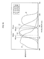
- the G1 filters transmit G light of a first wavelength band
- the G2 filters transmit G light of a second wavelength band highly correlated with the G1 filters (see Figure 18 ).
- the color imaging element acquires four types of colors in the image, and color information to be acquired is increased.
- colors can be more accurately expressed compared to when only three types of colors (RGB) are acquired. More specifically, visually different colors can be reproduced as different colors, and visually same colors can be reproduced as same colors ("color determination" can be improved).
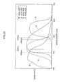
- the transparent filters W are filters of a transparent color (first color).
- the transparent filters W are filters that can transmit light corresponding to a wavelength band of visible light, and for example, whose transmittance of light of the RGB colors is 50% or more. Since the transmittance of the transparent filters W is higher than that of the G filters, the contribution ratio for obtaining the luminance signals is also higher than that of the G color (60%), and the condition (1) is satisfied.
- the peak of the transmittance of the transparent filters W (peak of the sensitivity of the white pixels) is in the range of wavelength 480 nm or more and 570 nm or less.
- the transmittance of the transparent filters W is higher than the transmittance of the RB filters in the range of wavelength 500 nm or more and 560 nm or less. Therefore, the transparent filters W also satisfy the conditions (2) and (3).
- the G filters also satisfy the conditions (1) to (3).
- the wavelength of the peak of the emerald filters E is shorter than that of the G filters in the spectral characteristics shown in Figure 20 , the wavelength of the peak is longer than that of the G filters (color looks a little closer to yellow) in some cases.
- the emerald filters E satisfying the conditions of the present invention can be selected, and for example, the emerald filters E satisfying the condition (1) can also be selected.
Landscapes
- Engineering & Computer Science (AREA)
- Multimedia (AREA)
- Signal Processing (AREA)
- Physics & Mathematics (AREA)
- Spectroscopy & Molecular Physics (AREA)
- Color Television Image Signal Generators (AREA)
- Solid State Image Pick-Up Elements (AREA)
Abstract
Description
- The present invention relates to a color imaging element, and particularly, to a color imaging element that can suppress generation of color moire and increase resolution.
- An output image of a single-plate color imaging element is a RAW image (mosaic image). Therefore, a multi-channel image is obtained by a process of interpolating (demosaicing process) a pixel of a missing color from a surrounding pixel.
- The demosaicing process is a process of calculating all color information of each pixel from a mosaic image corresponding to a color filter array of the single-plate color imaging element and is also called synchronization processing. For example, in a case of an imaging element including color filters of three RGB colors, the color information of all of RGB is calculated in the process for each pixel from the mosaic image made of RGB.
- In this case, there is a problem in reproduction characteristics of a highfrequency image signal. Compared to a black and white imaging element, aliasing easily occurs in an image taken by a color imaging element, and it is important to expand a reproduction band to increase resolution while suppressing generation of color moire (false color).
- A primary-color Bayer array as a color array most widely used in the single-plate color imaging element includes green (G) pixels arranged in a check pattern and red (R) and blue (B) arranged line-sequentially. Therefore, G signals have a problem of reproduction accuracy in generation of high frequency signals in oblique directions, and R and B signals have a problem of reproduction accuracy in generation of high frequency signals in horizontal and vertical directions.
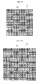
- A black and white vertical-striped pattern (high frequency image) as shown in (A) portion of
Figure 21 enters an imaging element in a Bayer array shown in (B) portion ofFigure 21 , and the pattern is sorted into Bayer color arrays to compare the colors. As shown in (C) to (E) portions ofFigure 21 , R forms a light and flat color image, B forms a dark and flat color image, and G forms a light and dark mosaic color image. Although there is no density difference (level difference) between RGB with respect to the original black and white image, the image is colored depending on the color array and the input frequency. - Similarly, a black and white oblique high frequency image as shown in (A) portion of
Figure 22 enters an imaging element in a Bayer array shown in (B) portion ofFigure 22 , and the image is sorted into Bayer color arrays to compare the colors. As shown in (C) to (E) portions ofFigure 22 , R and B form light and flat color images, while G forms a dark and flat color image. Assuming that the value of black is 0 and the value of white is 255, the black and white oblique high frequency image turns green, because only G is 255. - In this way, the oblique high frequency image cannot be correctly reproduced in the Bayer array.
- In the imaging apparatus using the single-plate color imaging element, an optical low-pass filter formed by an anisotropic substance such as crystal is generally arranged on the front side of the color imaging element to prevent optically reducing the high frequency wave. However, although the coloring caused by folding of the high frequency signal can be reduced in the method, there is a problem that the resolution is reduced accordingly.
- To solve the problem, a color imaging element is proposed, wherein a color filter array of the color imaging element is a three-color random array satisfying array restrictions in which an arbitrary target pixel is adjacent to three colors including the color of the target pixel on four sides of the target pixel (PTL 1).
- An image sensor of a color filter array is also proposed, wherein the image sensor includes a plurality of filters with different spectral sensitivity, and first and second filters among the plurality of filters are alternately arranged in a first predetermined period in one of the diagonal directions of a pixel grid of the image sensor and are alternately arranged in a second predetermined period in the other diagonal direction (PTL 2).
- A color array is further proposed, wherein in a color solid-state imaging element of three primary colors of RGB, sets of three pixels including horizontally arranged R, G, and B are arranged in a zigzag manner in the vertical direction to make appearance frequencies of RGB equal and to cause arbitrary lines (horizontal, vertical, and oblique lines) on an imaging plane to pass through all colors (PTL 3).
- Furthermore, a color imaging element is also proposed, wherein R and B among the three primary colors of RGB are arranged every three pixels in horizontal and vertical directions, and G is arranged between R and B (PTL 4).
- An imaging element is also proposed, wherein two G pixels are lined up in each of the horizontal direction and the vertical direction to arrange four pixels, and one on-chip lens is provided for the four pixel group (PTL 5).
-
- {PTL1}
Japanese Patent Application Laid-Open No.2000-308080 - {PTL 2}
Japanese Patent Application Laid-Open No.2005-136766 - {PTL 3}
Japanese Patent Application Laid-Open No.11-285012 - {PTL 4}
Japanese Patent Application Laid-Open No.8-23543 - {PTL 5}
Japanese Patent Application Laid-Open No.2011-29379 - In the color imaging element described in
PTL 1, the filter arrays are random, and each random pattern needs to be optimized in a demosaicing process in a later stage. There is a problem that the demosaicing process is cumbersome. Although the random arrays are effective for color moire in a low frequency wave, the random arrays are not effective for a false color at a high frequency section. - In the image sensor described in
PTL 2, the G pixels (luminance pixels) are arranged in a check pattern. Therefore, there is a problem that the pixel reproduction accuracy in a limit resolution area (particularly in oblique directions) is not excellent. - The color solid-state imaging element described in
PTL 3 includes filters of all colors on arbitrary lines and has an advantage that the generation of false color can be suppressed. However, the proportions of the numbers of pixels of RGB are equal, and there is a problem that the high frequency reproducibility is lower than that in a Bayer array. In the Bayer array, the proportion of the number of pixels of G that most contributes to obtaining luminance signals is twice the proportions of the numbers of pixels of R and B. - Meanwhile, in the color imaging element described in PTL 4, the proportion of the number of pixels of G with respect to the numbers of pixels of R and B is greater than that in the Bayer array, but there are lines with only G pixels in the horizontal or vertical direction. Therefore, the color imaging element is not effective for the false color at a high frequency section in the horizontal or vertical direction.
- In the imaging element described in PTL 4, four lined up G pixels and a set of diagonally arranged two B pixels and two R pixels are alternately lined up. Therefore, the imaging element is not effective in suppressing the generation of the false color.
- The present invention has been made in view of the circumstances, and an object of the present invention is to provide a color imaging element that can suppress the generation of false color and increase the resolution and that can simplify the process of a later stage compared to the conventional random array.
- To attain the object, a color imaging element according to an aspect of the present invention is a single-plate color imaging element including color filters in a specific color filter array, which includes first filters corresponding to a first color with one or more colors and second filters corresponding to a second color with two or more colors with contribution ratios for obtaining luminance signals lower than the first color, on a plurality of pixels formed by photoelectric conversion elements, wherein color filters of the same color are arranged on a predetermined number of vertically and horizontally adjacent photoelectric conversion elements, the color filter array includes a plurality of unit blocks, each unit block including the color filters arranged on the predetermined number of vertically and horizontally adjacent photoelectric conversion elements, the color filter array includes a basic array pattern including the unit blocks arranged in a square grid shape, the basic array pattern is repeatedly arranged in a horizontal direction and a vertical direction, one or more first filters are arranged in each line in the horizontal, vertical, upper right, and lower right directions of the color filter array, one or more second filters corresponding to each color of the second color are arranged in each line in the horizontal and vertical directions of the color filter array, and a proportion of the number of pixels of the first color corresponding to the first filters is greater than a proportion of the number of pixels of each color of the second color corresponding to the second filters.
- According to the color imaging element of the aspect of the present invention, the color filters of a predetermined color among the first filters corresponding to a first color with one or more colors and the second filters corresponding to a second color with two or more colors with the contribution ratios for obtaining the luminance signals lower than the first color are arranged on the predetermined number of vertically and horizontally adjacent photoelectric conversion elements, the color filter array includes the basic array pattern including the plurality of unit blocks arranged in the square grid shape, each unit block including the color filters arranged on the predetermined number of vertically and horizontally adjacent photoelectric conversion elements, and the basic array pattern is repeatedly arranged in the horizontal direction and the vertical direction.
- As a result, a process can be executed according to the repeated pattern in a demosaicing process in a later stage, and processing in the later stage can be simplified compared to the conventional random array.
- Since one or more first color filters are arranged in each line in the horizontal, vertical, upper right, and lower right directions of the color filter array, the reproduction accuracy of the demosaicing process in a high frequency area can be improved. Furthermore, one or more second filters are arranged in each line in the horizontal and vertical directions of the color filter array in the basic array pattern. This can suppress the generation of color moire (false color) to increase the resolution.
- The proportion of the number of pixels of the first color corresponding to the first filters and the proportion of the number of pixels of each color of the second color corresponding to the second filters are different, and particularly, the proportion of the number of pixels of the first color with the contribution ratio for obtaining the luminance signal is greater than the proportion of the number of pixels of each color of the second color corresponding to the second filters. Therefore, aliasing can be suppressed, and high frequency reproducibility can be improved.
- A color imaging element according to an aspect of the present invention is a single-plate color imaging element including color filters in a specific color filter array, which includes first filters corresponding to a first color with one or more colors and second filters corresponding to a second color with two or more colors with contribution ratios for obtaining luminance signals lower than the first color, on a plurality of pixels formed by photoelectric conversion elements arranged in a diagonal grid shape with centers of adjacent elements shifted at a 1/2 pixel pitch in a horizontal direction and a vertical direction, wherein color filters of the same color are arranged on a predetermined number of photoelectric conversion elements adjacent in upper right and lower right directions, the color filter array includes a plurality of unit blocks, each unit block including the color filters arranged on the predetermined number of photoelectric conversion elements adjacent in the upper right and lower right directions, the color filter array includes a basic array pattern including the unit blocks arranged in a diagonal grid shape, the basic array pattern is repeatedly arranged in the upper right and lower right directions, one or more first filters are arranged in each line in the horizontal, vertical, upper right, and lower right directions of the color filter array, one or more unit blocks provided with the second filters corresponding to each color of the second color are arranged in each line in the upper right and lower right directions of the color filter array, and a proportion of the number of pixels of the first color corresponding to the first filters is greater than a proportion of the number of pixels of each color of the second color corresponding to the second filters.
- According to the color imaging element of the aspect of the present invention, the color filters of the predetermined color among the first filters corresponding to a first color with one or more colors and the second filters corresponding to a second color with two or more colors with the contribution ratios for obtaining the luminance signals lower than the first color are arranged on the predetermined number of photoelectric conversion elements adjacent in the upper right and lower right directions among the photoelectric conversion elements arranged in the diagonal grid shape with the centers of the adjacent elements shifted at a 1/2 pixel pitch in the horizontal direction and the vertical direction, the color filter array includes the basic array pattern including the plurality of unit blocks arranged in the diagonal grid shape, each unit block including the color filters arranged on the predetermined number of photoelectric conversion elements adjacent in the upper right and lower right directions, and the basic array pattern is repeatedly arranged in the upper right and lower right directions.
- As a result, the process can be executed according to the repeated pattern in the demosaicing process in the later stage, and processing in the later stage can be simplified compared to the conventional random array.
- Since one or more first filters are arranged in each line in the horizontal, vertical, upper right, and lower right directions of the color filter array, the reproduction accuracy of the demosaicing process in a high frequency area can be improved. Furthermore, one or more second filters are arranged in each line in the upper right and lower right directions of the color filter array in the basic array pattern. This can suppress the generation of color moire (false color) to increase the resolution.
- The proportion of the number of pixels of the first color corresponding to the first filters and the proportion of the number of pixels of each color of the second color corresponding to the second filters are different, and particularly, the proportion of the number of pixels of the first color with a high contribution ratio for obtaining the luminance signal is greater than the proportion of the number of pixels of each color of the second color corresponding to the second filters. Therefore, aliasing can be suppressed, and high frequency reproducibility can be improved.
- In the color imaging element according to another aspect of the present invention, it is desirable that the predetermined number of photoelectric conversion elements include 4×4 pixels or 9×9 pixels.
- In the color imaging element according to another aspect of the present invention, it is desirable that the color filter array in the basic array pattern is point-symmetric with respect to the center of the basic array pattern.
- This can reduce the circuit size of a processing circuit in the later stage.
- In the color imaging element according to another aspect of the present invention, it is desirable that the basic array pattern is a unit block of N×N (N: integer 4 or more and 8 or less).
- In the color imaging element according to another aspect of the present invention, it is desirable that the basic array pattern is a unit block of 6×6.
- In the color imaging element according to another aspect of the present invention, it is desirable that in the color filter array, the unit blocks provided with the first filters are arranged at a center and four corners in 3×3 unit blocks. As a result, the first filters can be arranged in each line in the horizontal, vertical, upper right, and lower right directions of the color filter array.
- It is desirable that the color imaging element according to another aspect of the present invention includes pupil division means arranged above the photoelectric conversion elements, wherein light incident on the pupil division means is pupil-divided and guided to light receiving surfaces of the predetermined number of photoelectric conversion elements. As a result, a number of different image data that is the same number as the predetermined number can be acquired.
- In the color imaging element according to another aspect of the present invention, it is preferable that the first color is green (G), and the second color is red (R) and blue (B).
- In the color imaging element according to another aspect of the present invention, it is desirable that the basic array pattern is a square array pattern corresponding to a unit block of 6×6, and the color filter array includes first arrays and second arrays alternately arranged in the horizontal direction and the vertical direction, the first array corresponding to 3×3 unit blocks, the first array including unit blocks of G filters arranged at a center and four corners, the first array including unit blocks of B filters arranged above and below across the G filter at the center, the first array including unit blocks of R filters arranged on the left and right, the second array corresponding to 3×3 unit blocks, the second array including unit blocks of G filters arranged at a center and four corners, the second array including unit blocks of R filters arranged above and below across the G filter at the center, the second array including unit blocks of B filters arranged on the left and right. The present invention also includes an imaging apparatus including the color imaging element.
- According to the present invention, the generation of the false color can be suppressed, the resolution can be increased, and the processing in the later stage can be simplified compared to the conventional random array.
-
- {
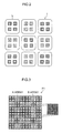
Figure 1} Figure 1 is a diagram showing a first embodiment of a single-plate color imaging element according to the present invention. - {
Figure 2} Figure 2 is a diagram showing a configuration example of light receiving surfaces of the color imaging element according to a first embodiment. - {
Figure 3} Figure 3 is a diagram showing a state in which a basic array pattern of 6×6 pixels included in a color filter array of the color imaging element of the first embodiment is divided into A arrays and B arrays of 3×3 pixels and arranged, the diagram also showing a method of determining a correlation direction from pixel values of G pixels of 2×2 pixels included in the color filter array. - {
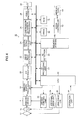
Figure 4} Figure 4 is a block diagram of an imaging apparatus using the color imaging element of the first embodiment. - {
Figure 5} Figure 5 is a diagram used to explain generation of parallax images. - {
Figure 6} Figure 6 is a diagram showing a color filter array of a color imaging element according to a first modified example of the first embodiment. - {
Figure 7} Figure 7 is a diagram showing a configuration example of light receiving surfaces of the color imaging element according to the first modified example of the first embodiment. - {
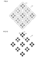
Figure 8} Figure 8 is a diagram showing a color filter array of a color imaging element according to a second modified example of the first embodiment. - {
Figure 9} Figure 9 is a diagram showing a configuration example of the light receiving surfaces of the color imaging element according to the second modified example of the first embodiment. - {
Figure 10} Figure 10 is a diagram showing a configuration example of light receiving surfaces of a color imaging element according to a third modified example of the first embodiment. - {
Figure 11} Figure 11 is a diagram showing a second embodiment of the single-plate color imaging element according to the present invention. - {
Figure 12} Figure 12 is a diagram showing a third embodiment of the single-plate color imaging element according to the present invention. - {
Figure 13} Figure 13 is a diagram showing a fourth embodiment of the single-plate color imaging element according to the present invention. - {
Figure 14} Figure 14 is a diagram showing a fifth embodiment of the single-plate color imaging element according to the present invention. - {
Figure 15} Figure 15 is a diagram showing a sixth embodiment of the single-plate color imaging element according to the present invention. - {
Figure 16} Figure 16 is a diagram showing a seventh embodiment of the single-plate color imaging element according to the present invention. - {
Figure 17} Figure 17 is a diagram showing an eighth embodiment of the single-plate color imaging element according to the present invention. - {
Figure 18} Figure 18 is a graph showing spectral sensitivity characteristics of a light receiving element provided with an R filter (red filter), a G1 filter (first green filter), a G2 filter (a second green filter), and a B filter (blue filter). - {
Figure 19} Figure 19 is a graph showing spectral sensitivity characteristics of a light receiving element provided with an R filter, a G filter, a B filter, and a W filter (transparent filter). - {
Figure 20} Figure 20 is a graph showing spectral sensitivity characteristics of a light receiving element provided with an R filter, a G filter, a B filter, and an emerald filter E (E filter). - {
Figure 21} Figure 21 is a diagram used to explain a problem of a color imaging element with color filters in a conventional Bayer array. - {
Figure 22} Figure 22 is another diagram used to explain a problem of a color imaging element with color filters in a conventional Bayer array. - Hereinafter, preferred embodiments of a color imaging element according to the present invention will be described in detail with reference to the attached drawings.
-
Figure 1 is a diagram showing a first embodiment of a single-plate color imaging element according to the present invention.Figure 1 particularly shows a color filter array of color filters arranged on the color imaging element. - This
color imaging element 1 includes: a plurality of pixels (not shown) formed by photoelectric conversion elements (for example, photodiodes) arranged in horizontal and vertical directions (two-dimensional arrangement); and color filters in a color filter array shown inFigure 1 arranged on light receiving surfaces of the pixels. One of the color filters of three primary colors of red (R), green (G), and blue (B) is arranged on each pixel. - The color imaging element is not limited to a CCD (Charge Coupledl) evice) color imaging element and may be another type of imaging element such as a CMOS (Complementary Metal Oxide Semiconductor) imaging element.
- As shown in
Figure 1 , color filters of the same color are arranged for four vertically and horizontally adjacent photoelectric conversion elements. As shown inFigure 2 , one microlens L is arranged for the four photoelectric conversion elements provided with the color filters of the same color. The microlens L collects the light flux on the light receiving surfaces of the four photoelectric conversion elements, and light with the light flux limited in different directions (pupil-divided light) is incident on the four photoelectric conversion elements. More specifically, thecolor imaging element 1 can acquire image data from four viewpoints. - According to the
color imaging element 1, a 2D image and a 3D image can be generated based on output signals output from the four photoelectric conversion elements that receive the light which is pupil-divided by the microlens L. A generation method of the 2D image and the 3D image will be described later. - The color filter array of the color imaging element of the first embodiment has the following features (1), (2), (3), (4), (5), and (6). Hereinafter, the color filters of the same color arranged for the four photoelectric conversion elements that receive the object light passed through one microlens L will be described as a unit block.
- The color filter array shown in
Figure 1 includes a basic array pattern PI (pattern indicated by a thick frame) formed by a square array pattern corresponding to 6×6 blocks, and the basic array pattern PI is repeatedly arranged in the horizontal and vertical directions. Therefore, the color filter array includes filters of R, G, and B colors (R filters, G filters, and B filters) arranged in a cycle. - In this way, the R filters, the G filters, and the B filters are arranged in a cycle. Therefore, a demosaicing process and the like of R, G, and B signals read out from the color imaging element can be processed according to the repeated pattern.
- When a thinning-out process is executed based on the basic array pattern PI to reduce the image, the color filter array of the reduced image after the thinning-out process can be the same as the color filter array before the thinning-out process. Therefore, a common processing circuit can be used.
- In the color filter array shown in
Figure 1 , the one or more G filters corresponding to the color (color of G in the embodiment) that most contributes to obtaining luminance signals are arranged in each line in the horizontal, vertical, and oblique (NE, NW) directions of the color filter array. Reference character NE designates an upper right direction, and reference character NW designates a lower right direction. For example, in a case of an array of square pixels, the upper right and lower right directions are directions of 45° from the horizontal direction. In a case of an array of rectangular pixels, the upper right and lower right directions are directions of the diagonal lines of the rectangle, and the angles may vary depending on the lengths of the long side and the short side. - The G filters corresponding to the luminance pixels are arranged in each line in the horizontal, vertical, and oblique (NE, NW) directions of the color filter array. Therefore, the reproduction accuracy of the demosaicing process in a high frequency area can be improved regardless of the direction of the high frequency wave.
- In the basic array pattern P1 of the color filter array shown in
Figure 1 , the numbers of pixels of the R pixels, the G pixels, and the B pixels corresponding to the R, G, and B filters in the basic array pattern P1 are 32 pixels (4 pixels × 8 blocks), 80 pixels (4 pixels × 20 blocks), and 32 pixels (4 pixels × 8 blocks), respectively. Therefore, the ratio of the numbers of pixels of the RGB pixels is 2:5:2, and the proportion of the number of G pixels that most contribute to obtaining the luminance signals is greater than the proportions of the numbers of R and B pixels of other colors. - The proportion of the number of G pixels and the proportions of the numbers of R and B pixels are different, and particularly, the proportion of the number of G pixels that most contribute to obtaining the luminance signals is greater than the proportions of the numbers of R and B pixels. Therefore, aliasing in the demosaicing processing can be suppressed, and high frequency reproducibility can be improved.
- In the color filter array shown in
Figure 1 , one or more R and B filters corresponding to two or more colors other than the color of G (colors of R and B in the embodiment) are arranged in each line in the horizontal and vertical directions of the color filter array in the basic array pattern PI. - The R and B filters are arranged in each line in the horizontal and vertical directions of the color filter array. Therefore, the generation of color moire (false color) can be suppressed. As a result, it is possible not to arrange an optical low-pass filter for suppressing the generation of false color on an optical path from a plane of incident to an imaging plane of the optical system. Even if the optical low-pass filter is applied, a filter with less effect of cutting high frequency components for preventing the generation of false color can be applied, and a loss of resolution can be prevented.
-
Figure 3 shows a state in which the basic array pattern PI shown inFigure 1 is divided into four sets of 3×3 blocks. - As shown in
Figure 3 , the basic array pattern PI can be perceived as a pattern including A arrays of 3×3 blocks surrounded by a frame of solid lines and B arrays of 3×3 blocks surrounded by a frame of broken lines alternately arranged in the horizontal and vertical directions. - Each of the A and B arrays includes G filters as luminance pixels arranged on blocks at four corners and a center. In other words, the G filters are arranged on both diagonals. In the A array, the R filters are arranged in the horizontal direction, and the B filters are arranged in the vertical direction, across the G filter at the center. Meanwhile, in the B array, the B filters are arranged in the horizontal direction, and the R filters are arranged in the vertical direction, across the G filter at the center. Therefore, although the positional relationship between the R and B filters is opposite in the A and B arrays, the rest of the arrangement is the same.
- The A and B arrays are alternately arranged in the horizontal and vertical directions as shown in
Figure 3 , and the G filters at four corners of the A and B arrays form G filters of square arrays corresponding to 2×2 blocks. - The G filters as luminance pixels are arranged on the blocks at the four corners and the center in 3×3 blocks in the A and B arrays, that is, on two diagonals, and the 3×3 blocks are alternately arranged in the horizontal and vertical directions to form the G filters in the square arrays corresponding to 2×2 pixels. The arrays satisfy the features (1), (2), and (3), as well as a feature (5) described below.
- The color filter array shown in
Figure 1 includes square arrays corresponding to 2x2 blocks of G filters. - As shown in
Figure 4 , 2×2 blocks of G filters are extracted to calculate difference absolute values of the pixel values of the G pixels in the horizontal direction, difference absolute values of the pixel values of the G pixels in the vertical direction, and difference absolute values of the pixel values of the G pixels in the oblique directions (upper right oblique and upper left oblique directions). In this way, it can be determined that there is a correlation in the direction with a small difference absolute value among the horizontal, vertical, and oblique directions. - Therefore, according to the color filter array, information of the G pixels at minimum pixel intervals can be used to determine the direction with a high correlation among the horizontal, vertical, and oblique directions. The direction determination result can be used for a process of interpolation (demosaicing processing) based on surrounding pixels.
- When the pixels of the A or B array of 3×3 blocks are the target pixels of the demosaicing process, and 5×5 blocks (local area of mosaic image) are extracted around the A or B array, there are G pixels of 2×2 blocks at four corners of the 5×5 blocks. The pixel values of the G pixels of 2×2 blocks can be used to accurately determine the correlation direction of four directions using the information of the G pixels at minimum pixel intervals.
- The basic array pattern P1 of the color filter array shown in
Figure 1 is point-symmetric. More specifically, the basic array pattern P1 is point-symmetric with respect to the center of the basic array pattern P1. The A and B arrays in the basic array pattern P1 are also point-symmetric with respect to the G filter at the center. Furthermore, the A and B arrays in the basic array pattern P1 are line symmetric with respect to the line in the horizontal or vertical direction through the centers of the A and B arrays. - The symmetry can reduce and simplify the circuit size of a processing circuit in a later stage.
- In the basic array pattern PI shown by a thick frame as shown in
Figure 1 , color filter arrays of first and third lines among first to sixth lines in the horizontal direction include GBGGRG, a color filter array of the second line includes RGRBGB, color filter arrays of the fourth and sixth lines include GRGGBG, and a color filter array of the fifth line includes BGBRGR. - In
Figure 1 , assuming that a basic array pattern obtained by shifting the basic array pattern PI by one block both in the horizontal and vertical directions is PI' and a basic array pattern obtained by shifting the basic array pattern PI by two blocks both in the horizontal and vertical directions is PI", the color filter array is the same even if the basic array patterns PI' and PI" are repeatedly arranged in the horizontal and vertical directions. - Therefore, there are a plurality of basic array patterns that can form the color filter array shown in
Figure 1 by repeatedly arranging the basic array pattern in the horizontal and vertical directions. - In the first embodiment, the basic array pattern P in which the basic array pattern is point-symmetric is called a basic array pattern for convenience.
- Although there are also a plurality of basic array patterns for each of the color filter arrays in the other embodiments described below, the representative one will be called a basic array pattern of the color filter array.
-
Figure 4 is a block diagram showing an embodiment of animaging apparatus 10 according to the present invention. - The
imaging apparatus 10 is provided with the color imaging element (imaging device) 1 shown inFigure 1 and can take a 2D image and a 3D image. A central processing unit (CPU) 40 comprehensively controls the operation of the entire apparatus. - The
imaging apparatus 10 includes anoperation unit 38, such as a shutter button, a mode dial, a replay button, a MENU/OK key, arrow keys, and a BACK key. A signal from theoperation unit 38 is input to theCPU 40. TheCPU 40 controls circuits of theimaging apparatus 10 based on the input signal and performs, for example, lens drive control, aperture drive control, imaging operation control, image processing control, recording/replay control of image data, and display control of a liquid crystal monitor 30 for three-dimensional display. - The shutter button is an operation button for inputting an instruction for starting imaging and is provided with two-stage stroke switches including an S1 switch turned on when half-pressed and an S2 switch turned on when full-pressed. The mode dial is selection means for selecting a 2D imaging mode, a 3D imaging mode, an auto imaging mode, a manual imaging mode, a scene position of a person, a landscape, or a night scene, a macro mode, and a movie mode, as well as a parallax priority imaging mode according to the present invention.
- The replay button is a button for switching to a replay mode for displaying still images or moving images of a plurality of taken and recorded parallax images (3D images) and plane images (2D images) on the
liquid crystal monitor 30. The MENU/OK key is an operation key having a function of a menu button for commanding to display a menu on the screen of the liquid crystal monitor 30 and a function of an OK button for commanding to confirm and execute the selected content. The arrow keys are an operation unit for inputting instructions of four vertical and horizontal directions, and the arrow keys function as buttons (cursor movement operation means) for selecting an item from the menu screen or for instructing to select various setting items from each menu. Up and down keys of the arrow keys function as zoom switches in the imaging or as replay zoom switches in the relay mode, and left and right keys function as frame advance (forward direction/opposite direction advance) buttons in the replay mode. The BACK key is used to delete a desired target of a selected item or the like, to cancel the instructed content, or to restore the previous operation state. - In the imaging mode, an image of image light indicating the object is formed on the light receiving surfaces of the
color imaging element 1 through a single imaging optical system (zoom lens) 12 and anaperture 14. The imagingoptical system 12 is driven by alens drive unit 36 controlled by theCPU 40, and focus control, zoom control, and the like are performed. Theaperture 14 includes, for example, five aperture blades. Anaperture drive unit 34 controlled by theCPU 40 drives theaperture 14, and for example, theaperture 14 is controlled in six stages from aperture value F1.4 to F11 on an AV to AV basis. - The
CPU 40 controls theaperture 14 through theaperture drive unit 34 and performs control of electric charge accumulation time (shutter speed) in thecolor imaging element 1 through adevice control unit 32, reading control of an image signal from thecolor imaging element 1, and the like. - The signal charge accumulated in the
color imaging element 1 is read as a voltage signal corresponding to the signal charge based on a read signal added from thedevice control unit 32. The voltage signal read from thecolor imaging element 1 is added to an analogsignal processing unit 18, and the R, G, and B signals of the pixels are sampled and held here. The signal is amplified by a gain (equivalent to ISO sensitivity) designated from theCPU 40 and then added to an A/D converter 20. - The A/
D converter 20 converts the sequentially input R, G, and B signals to digital R, G, and B signals and output the signals to animage input controller 22. - A digital
signal processing unit 24 applies signal processing to the digital image signals input through theimage input controller 22, such as an offset process, a gain control process including white balance correction and sensitivity correction, a gamma correction process, a demosaicing process, a YC process, and sharpness correction. - In
Figure 4 ,reference numeral 46 designates a ROM (EEPROM) storing a camera control program, defect information of thecolor imaging element 1, various parameters and tables used for image processing and the like, an aperture priority program diagram, a shutter speed priority program diagram, and a program diagram (normal program diagram) for alternately or concurrently changing the aperture and the shutter speed according to the brightness of the object, as well as a parallax priority program diagram and the like. - The parallax priority program diagram is designed, for example, to set an F value to a constant value of 5.6 (AV = 5) and to change only the shutter speed from 1/60 seconds (TV = 6) to 1/2000 (TV =11) according to an imaging EV value when the imaging EV value is from 11 to 16. When the imaging EV value is smaller (darker) than 11, the parallax priority program diagram is designed to change the ISO sensitivity from 100 to 200, 400, 800, 1600, and 3200 every time the imaging EV value is reduced by 1 EV, while the F value = 5.6 and the shutter speed = 1/60 seconds are fixed. The parallax priority program diagram is not limited to this. Since the parallax of the parallax images from four viewpoints obtained from the
color imaging element 1 changes according to the size of the aperture opening, the aperture opening may be controlled to avoid the aperture opening from becoming smaller than a certain aperture opening in the 3D imaging mode. - The digital
signal processing unit 24 executes image processing according to one of the 2D imaging mode and the 3D imaging mode and executes image processing according to the object and imaging conditions. Details of the image processing in the digitalsignal processing unit 24 will be described later. - When the 2D imaging mode is selected, 2D image data processed by the digital
signal processing unit 24 is output to aVRAM 50. On the other hand, when the 3D imaging mode is selected, 3D image data processed by the digitalsignal processing unit 24 is output to theVRAM 50. TheVRAM 50 includes an A area and a B area, each storing image data indicating an image of one frame. In theVRAM 50, the image data indicating an image of one frame is alternately rewritten in the A area and the B area. Of the A area and the B area of theVRAM 50, the written image data is read from the area other than the area in which the image data is rewritten. Avideo encoder 28 encodes the image data read from theVRAM 50, and the image data is output to the liquid crystal monitor 30 for three-dimensional display arranged on the back side of the camera. In this way, a 2D/3D object image (live view image) is displayed on the display screen of theliquid crystal monitor 30. - The liquid crystal monitor 30 is three-dimensional display means that can display a stereoscopic image (left viewpoint image and right viewpoint image) as a directional image with directivity, through a parallax barrier. The liquid crystal monitor 30 is not limited to this, and a lenticular lens may be used, or the left viewpoint image and the right viewpoint image may be individually viewed by wearing special glasses, such as polarization glasses and liquid crystal shutter glasses.
- When there is a press (half-press) of the first stage of the shutter button of the
operation unit 38, thecolor imaging element 1 starts AF operation and AE operation and controls the focus lens in the imagingoptical system 12 to come to the focal position through thelens drive unit 36. AnAE detection unit 44 imports the image data output from the A/D converter 20 when the shutter button is half-pressed. - The
AE detection unit 44 integrates the G signals of the entire screen or integrates the G signals by applying different weights to the screen center and the surrounding. TheAE detection unit 44 outputs the integrated value to theCPU 40. TheCPU 40 calculates the brightness (imaging EV value) of the object based on the integrated value input from theAE detection unit 44 and determines the aperture value of theaperture 14 and the electronic shutter (shutter speed) of thecolor imaging element 1 based on the imaging EV value according to a program diagram. - In the program diagram, imaging (exposure) conditions including combinations of the aperture values of aperture and the shutter speed or combinations of these and the imaging sensitivity (ISO sensitivity) are designed according to the brightness of the object, and an image can be taken by the imaging conditions determined according to the program diagram to take an image with appropriate brightness, regardless of the brightness of the object.
- The
CPU 40 controls theaperture 14 through theaperture drive unit 34 based on the aperture value determined according to the program diagram and controls the electric charge accumulation time in thecolor imaging element 1 through thedevice control unit 32 based on the determined shutter speed. - An
AF processing unit 42 is a portion that executes contrast AF processing or phase AF processing. In the phase difference AF processing, for example, the phase difference of the image data in the focus detection area of the plurality of parallax image data generated in certain blocks is detected, and the amount of defocus is obtained based on information indicating the phase difference. The AF control is performed by controlling the focus lens in the imagingoptical system 12 so that the amount of defocus becomes 0. In the contrast AF processing, high frequency components of the image data in the focus detection area of the image data are extracted, and the high frequency components are integrated to calculate an AF evaluation value indicating the focus state. The AF control is performed by controlling the focus lens in the imagingoptical system 12 to maximize the AF evaluation value. - When there is a press (full-press) of the second stage of the shutter button after the AE operation and the AF operation are finished, the image data output from the A/
D converter 20 in response to the press is input from theimage input controller 22 to a memory (SDRAM) 48 and is temporarily stored. - The digital
signal processing unit 24 appropriately reads the image data temporarily stored in thememory 48. Predetermined image processing is applied to the image data, including a demosaicing process (process of converting color signals to a synchronous system by interpolating spatial deviation of the color signals associated with the array of the primary color filters) and a YC process (generation process of luminance data and color difference data of image data). The YC-processed image data (YC data) is stored again in thememory 48. - In the 2D imaging mode, assuming that the pixels of the blocks are A, B, C, and D as shown in
Figure 2 , the digitalsignal processing unit 24 adds four image data of A, B, C, and D for each block to generate image data of one pixel. - In the 3D imaging mode, the digital
signal processing unit 24 generates four image data of A, B, C, and D. When theimaging apparatus 10 is horizontally set to take an image, the digitalsignal processing unit 24 adds the image data of A and C to generate a left eye display image (left parallax image) and adds the image data of B and D to generate a right eye display image (right parallax image) as shown inFigure 5 . On the other hand, when theimaging apparatus 10 is vertically set to take an image, the digitalsignal processing unit 24 adds the image data of A and B to generate a left eye display image (left parallax image) and adds the image data of C and D to generate a right eye display image (right parallax image). Theimaging apparatus 10 includes a sensor that detects the posture (vertical and horizontal) of theimaging apparatus 10, and the addition of the pixels is selectively performed based on the posture of theimaging apparatus 10 in the 3D imaging. In this way, a three-dimensional image can be taken regardless of the posture of theimaging apparatus 10. When theimaging apparatus 10 is vertically set to take an image, the digitalsignal processing unit 24 may add the image data of A and B to generate a right eye display image (right parallax image) and may add the image data of C and D to generate a left eye display image (left parallax image). The array of the photodiodes of thecolor imaging element 1 is in a square grid shape, and the image data can be easily added in the generation of the parallax images. Therefore, the noise of the parallax images can be reduced. - Subsequently, the digital
signal processing unit 24 applies predetermined signal processing including the demosaicing process and the YC process to the image data. The YC-processed YC data is stored again in thememory 48. - The generated YC data of one image stored in the
memory 48 is output to a compressionexpansion processing unit 26, and predetermined compression processing, such as JPEG (joint photographic experts group) is applied here. The YC data is recorded in amemory card 54 through amedia controller 52. The YC data of two images (left and right viewpoint images) generated in the 3D imaging mode and stored in thememory 48 is output to the compressionexpansion processing unit 26, and compression processing, such as JPEG (joint photographic experts group), is applied here. A multi-picture file (MP file: file in a format of connecting a plurality of images) is further generated, and the MP file is recorded in thememory card 54 through themedia controller 52. - Although the left and right two parallax images are generated as shown in
Figure 5 in the 3D imaging mode, the arrangement is not limited to this. The vertical and horizontal four parallax images may be recorded, and the images may be added as shown inFigure 5 to output parallax images in the 3D replay. - In a first modified example of the first embodiment, the number of pixels of the unit block is different from the first embodiment.
- Since the color filter array according to the first modified example of the first embodiment is the same as the color filter array of the first embodiment, a color imaging element 1-1 according to the first modified example of the first embodiment has the features (1), (2), (3), (4), (5), and (6) as in the first embodiment. Although the first modified example of the first embodiment will be described below, the same portions as in the first embodiment will not be described, and only portions different from the first embodiment will be described.
- As shown in
Figure 6 , the color imaging element 1-1 is an imaging device, such as a CCD and a COMS, and includes: a plurality of pixels (not shown) with photoelectric conversion elements arranged in the horizontal direction and the vertical direction (two-dimensional arrangement); and color filters of the color filter array shown inFigure 6 arranged on the light receiving surfaces of the pixels. One of the color filters of three primary colors of red (R), green (G), and blue (B) is arranged on each pixel. - As shown in
Figure 6 , color filters of the same color are arranged for nine vertical and horizontal photoelectric conversion elements. As shown inFigure 7 , one microlens L-1 is arranged for the nine photoelectric conversion elements provided with the color filters of the same color. The microlens L-1 collects the light flux on the light receiving surfaces of the nine photoelectric conversion elements, and light with the light flux limited in nine vertical and horizontal directions (pupil-divided light) is incident on the nine photoelectric conversion elements. More specifically, the color imaging element 1-1 can acquire image data from nine viewpoints. Assuming that the pixels of the blocks are A, B, C, D, E, F, G, H, and I as shown inFigure 7 , the pixel E at the center is a pixel that receives the light flux from the front side of an imaging apparatus 10-1 (not shown), and A, B, C, D, F, G, H, and I receive the light flux from other than the front side of the imaging apparatus 10-1. - According to the color imaging element 1-1, a 2D image and a 3D image can be generated based on output signals output from the nine photoelectric conversion elements that receive the light which is pupil-divided by the microlens L.
- In the 2D imaging mode, a digital signal processing unit 24-1 (not shown) uses only the image data of the E pixel of each block to generate image data of one pixel. Nine image data of A, B, C, D, E, F, G, H, and I may be added for each block to generate image data of one pixel.
- In the 3D imaging mode, the digital signal processing unit 24-1 generates nine image data of A, B, C, D, E, F, G, H, and I. When the imaging apparatus 10-1 (not shown) is horizontally set to take an image, the digital signal processing unit 24-1 adds the image data of A, D, and G to generate a left eye display image (left parallax image) and adds the image data of C, F, and I to generate a right eye display image (right parallax image). On the other hand, when the imaging apparatus 10-1 is vertically set to take an image, the digital signal processing unit 24-1 adds the image data of A, B, and C to generate a left eye display image (left parallax image) and adds the image data of G, H, and I to generate a right eye display image (right parallax image). When the imaging apparatus 10-1 is vertically set to take an image, the digital signal processing unit 24-1 may add the image data of A, B, and C to generate a right eye display image (right parallax image) and may add the image data of G, H, and I to generate a left eye display image (left parallax image).
- The number of pixels of the unit block is not limited to four or nine, and various modes can be used.
- In a second modified example of the first embodiment, the alignment of the photodiodes is different from the first embodiment.
- Since the color filter array according to the first modified example of the first embodiment is the same as the color filter array of the first embodiment, a color imaging element 1-2 according to the second modified example of the first embodiment has the features (1), (2), (3), (4), (5), and (6) as in the first embodiment. Although the second modified example of the first embodiment will be described below, the same portions as in the first embodiment will not be described, and only portions different from the first embodiment will be described.
- As shown in
Figure 8 , the color imaging element 1-2 includes a plurality of photoelectric conversion elements arranged in a diagonal grid shape. More specifically, the centers of adjacent photoelectric conversion elements are shifted at a 1/2 pixel pitch in the horizontal direction and the vertical direction. In this way, the color imaging element 1-2 corresponds to thecolor imaging element 1 ofFigure 1 rotated by 45°. - As shown in
Figure 8 , the color imaging element 1-2 is provided with color filters of the same color for four photoelectric conversion elements adjacent in upper right and lower right directions. As shown inFigure 9 , one microlens L is arranged for the four photoelectric conversion elements provided with the color filters of the same color. In the present embodiment, the color filters of the same color arranged for the four photoelectric conversion elements will be described as a unit block. - The microlens L-2 collects the light flux on the light receiving surfaces of the four photoelectric conversion elements, and light with the light flux limited in four vertical and horizontal directions (pupil-divided light) is incident on the four photoelectric conversion elements. More specifically, the color imaging element 1-2 can acquire image data from four viewpoints.
- According to the color imaging element 1-2, a 2D image and a 3D image can be generated based on output signals output from the four photoelectric conversion elements that receive the light which is pupil-divided by the microlens L. A generation method of the 2D image and the 3D image will be described later.
- The color filter array shown in
Figure 8 includes a basic array pattern P1-2 (pattern indicated by a thick frame) formed by a diagonal grid array pattern corresponding to 6×6 blocks, and the basic array pattern P1-2 is repeatedly arranged in a diagonal grid shape. - Although the color filter array shown in
Figure 8 corresponds to the color filter array of the first embodiment shown inFigure 1 rotated by 45°, the color filter array shown inFigure 8 includes G filters arranged in each line in the horizontal, vertical, and oblique (NE, NW) directions of the color filter array as in the color filter array of the first embodiment. - In the basic array pattern P1-2 of the color filter array shown in
Figure 8 , the numbers of pixels of the R pixels, the G pixels, and the B pixels corresponding to the R, G, and B filters in the basic array pattern P1-2 are 32 pixels (4 pixels × 8 blocks), 80 pixels (4 pixels × 20 blocks), and 32 pixels (4 pixels × 8 blocks), respectively. Therefore, the ratio of the numbers of pixels of the RGB pixels is 2:5:2, and the proportion of the number of G pixels that most contribute to obtaining the luminance signals is greater than the proportions of the numbers of R and B pixels of other colors. - The proportion of the number of G pixels and the proportions of the numbers of R and B pixels are different, and particularly, the proportion of the number of G pixels that most contribute to obtaining the luminance signals is greater than the proportions of the numbers of R and B pixels, as described above. Therefore, aliasing in the demosaicing process can be suppressed, and high frequency reproducibility can be improved.
- In the color filter array of the first embodiment shown in
Figure 1 , one or more R and B filters are arranged in each line in the horizontal and vertical directions of the color filter array in the basic array pattern P1. However, since the color filter array according to the second modified example of the first embodiment corresponds to the color filter array of the first embodiment rotated by 45° as shown inFigure 8 , one or more R and B filters are arranged in each line in the oblique (NE, NW) directions of the color filter array in the basic array pattern P1-2. - The A and B arrays are alternately arranged in the diagonal grid shape, and the G filters at four corners of the A and B arrays form G filters of a diagonal grid array corresponding to 2×2 pixels (array in an arrow shape with vertically and horizontally adjacent four pixels).
- This is because the G filters as luminance pixels are arranged at the four corners and the center in 3×3 blocks in the A and B arrays, and the 3×3 pixels are arranged in the diagonal grid shape to form the G filters in the diagonal grid array corresponding to 2×2 pixels.
- The basic array pattern P1-2 of the color filter array shown in
Figure 8 is point-symmetric. More specifically, the basic array pattern PI-2 is point-symmetric with respect to the center of the basic array pattern P1-2. The A and B arrays in the basic array pattern PI-2 are also point-symmetric with respect to the G filter at the center. Furthermore, the A and B arrays in the basic array pattern P1-2 are line symmetric with respect to the line in the NE or NW direction through the centers of the A and B arrays. - The symmetry can reduce and simplify the circuit size of a processing circuit in a later stage.
- In this way, the color imaging element 1-2 according to the second modified example of the first embodiment corresponds to the color imaging element of the first embodiment rotated by 45°. Therefore, the reproducible band in the horizontal and vertical directions is √2 times that of the
color imaging element 1 arranged in the square grid shape. The characteristics match with the frequency characteristics of human vision that are higher in the horizontal and vertical directions than in the oblique directions, and this structure is visually advantageous. - In the 2D imaging mode, a digital signal processing unit 24-2 (not shown) adds four image data of A, B, C, and D for each block to generate image data of one pixel.
- In the 3D imaging mode, the digital signal processing unit 24-2 generates four image data of A, B, C, and D. When an imaging apparatus 10-2 (not shown) is horizontally set to take an image, the digital signal processing unit 24-2 generates a left eye display image (left parallax image) from the image data of B and generates a right eye display image (right parallax image) from the image data of C. On the other hand, when the
imaging apparatus 10 is vertically set to take an image, the digital signal processing unit 24-2 generates a left eye display image (left parallax image) from the image data of A and generates an observation display image (right parallax image) from the image data of D. When theimaging apparatus 10 is vertically set to take an image, the digital signal processing unit 24-2 may generate a left eye display image (left parallax image) from the image data of D and may generate a right eye display image (right parallax image) from the image data of A. - In the color imaging element 1-2 according to the second modified example of the first embodiment, the centers of the adjacent photoelectric conversion elements are shifted at a 1/2 pixel pitch in the horizontal and vertical directions. Therefore, the parallax in the horizontal direction (interval between A and D) and the parallax in the vertical direction (interval between B and D) of the color imaging element 1-2 are wider than the parallax in the horizontal direction (interval between A and B or between C and D) and the parallax in the vertical direction (interval between A and C or between B and D) of the
color imaging element 1 of the first embodiment. Therefore, the parallax of the parallax image is greater, and a more effective parallax image can be taken. - In a first modified example of the first embodiment, the method of pupil division is different from the second modified example of the first embodiment. Although the third modified example of the first embodiment will be described below, the same portions as in the second modified example of the first embodiment will not be described, and only portions different from the second modified example of the first embodiment will be described.
- In the second modified example of the first embodiment, one microlens L-2 is arranged for the four photoelectric conversion elements provided with the color filters of the same color as shown in
Figure 9 . In the third modified example of the first embodiment, light blocking members S1 to S4 are arranged on the front surfaces of the light receiving surfaces of the four photoelectric conversion elements. As shown in Figure 10, the light blocking member S1 that blocks substantially the lower half of the light flux is arranged on the pixel corresponding to A ofFigure 9 in a color imaging element 1-2'. The light blocking member S2 that blocks substantially the right half of the light flux is arranged on the pixel corresponding to B ofFigure 9 . The light blocking member S3 that blocks substantially the left half of the light flux is arranged on the pixel corresponding to C ofFigure 9 . The light blocking member S4 that blocks substantially the upper half of the light flux is arranged on the pixel corresponding to D ofFigure 9 . In this way, light with the light flux limited in four vertical and horizontal directions (pupil-divided light) is incident on the four photoelectric conversion elements provided with the color filters of the same color. More specifically, the color imaging element 1-2 can acquire image data from four viewpoints. - In a single-plate color imaging element according to a second embodiment of the present invention, only the color filter array of the color filters arranged on the color imaging element is different from the single-plate color imaging element according to the first embodiment. Although the second embodiment will be described below, the same portions as in the first embodiment will not be described, and only the color filter array different from the first embodiment will be described.
-
Figure 11 is a diagram showing the second embodiment of the single-plate color imaging element according to the present invention, andFigure 11 particularly illustrates a color filter array of color filters arranged on acolor imaging element 2. The color filter array of the color imaging element of the second embodiment has the following features (1), (2), (3), (4), and (6). - The color filter array of the
color imaging element 2 includes a basic array pattern P2 (pattern indicated by a thick frame) formed by a square array pattern corresponding to 4×4 blocks, and the basic array pattern P2 is repeatedly arranged in the horizontal and vertical directions. - In the color filter array shown in
Figure 11 , G filters are arranged in each line in the horizontal, vertical, and oblique (NE, NW) directions of the color filter array as in the first embodiment. - In the basic array pattern P2 of the color filter array shown in
Figure 11 , the numbers of pixels of the R pixels, the G pixels, and the B pixels corresponding to the R, G, and B filters in the basic array pattern are 16 pixels (4 blocks × 4 pixels), 32 pixels (8 blocks × 4 pixels), and 16 pixels (4 blocks × 4 pixels), respectively. Therefore, the ratio of the numbers of pixels of the RGB pixels is 1:2:1, and the proportion of the number of G pixels that most contribute to obtaining the luminance signals is greater than the proportions of the numbers of R and B pixels of other colors. - In the color filter array shown in
Figure 11 , the R and B filters are arranged in each line in the horizontal and vertical directions of the color filter array as in the first embodiment. - The basic array pattern P2 shown in
Figure 11 is point-symmetric with respect to the center of the basic array pattern P2. - The color filter array shown in
Figure 11 does not include a square array corresponding to 2×2 blocks of G filters. (Therefore, feature (5) is not satisfied. The same applies hereinafter.) However, the color filter array shown inFigure 11 includes G filters adjacent in the horizontal direction and G filters adjacent in the oblique (NE, NW) directions. Since the G filters exist across the R filters or the B filters in the vertical direction, the pixel values of the G pixels corresponding to the G filters can be used to determine the correlation in the vertical direction. - In a single-plate color imaging element according to a third embodiment of the present invention, only the color filter array of the color filters arranged on the color imaging element is different from the single-plate color imaging element according to the first embodiment. Although the third embodiment will be described below, the same portions as in the first embodiment will not be described, and only the color filter array different from the first embodiment will be described.
-
Figure 12 is a diagram showing the third embodiment of the single-plate color imaging element according to the present invention, andFigure 12 particularly illustrates a color filter array of color filters arranged on acolor imaging element 3. The color filter array of the color imaging element of the third embodiment has the following features (1), (2), (3) and (4). - The color filter array of the
color imaging element 3 includes a basic array pattern P3 (pattern indicated by a thick frame) formed by a square array pattern corresponding to 5×5 blocks, and the basic array pattern P3 is repeatedly arranged in the horizontal and vertical directions. - In the color filter array shown in
Figure 12 , G filters are arranged in each line in the horizontal, vertical, and oblique (NE, NW) directions of the color filter array as in the first embodiment. - In the basic array pattern P3 of the color filter array shown in
Figure 12 , the numbers of pixels of the R pixels, the G pixels, and the B pixels corresponding to the R, G, and B filters in the basic array pattern P3 are 28 pixels (7 blocks × 4 pixels), 44 pixels (11 blocks × 4 pixels), and 28 pixels (7 blocks × 4 pixels), respectively. Therefore, the ratio of the numbers of pixels of the RGB pixels is 7:11:7, and the proportion of the number of G pixels that most contribute to obtaining the luminance signals is greater than the proportions of the numbers of R and B pixels of other colors. - In the color filter array shown in
Figure 12 , the R and B filters are arranged in each line in the horizontal and vertical directions of the color filter array as in the first embodiment. - The color filter array shown in
Figure 12 does not include a square array corresponding to 2×2 blocks of G filters. The basic array pattern P3 is not point-symmetric. (Therefore, feature (6) is not satisfied. The same applies hereinafter.) - In a single-plate color imaging element according to a fourth embodiment of the present invention, only the color filter array of the color filters arranged on the color imaging element is different from the single-plate color imaging element according to the first embodiment. Although the fourth embodiment will be described below, the same portions as in the first embodiment will not be described, and only the color filter array different from the first embodiment will be described.
-
Figure 13 is a diagram showing the fourth embodiment of the single-plate color imaging element according to the present invention, andFigure 13 particularly illustrates a color filter array of color filters arranged on a color imaging element 4. The color filter array of the color imaging element of the fourth embodiment has the following features (1), (2), (3) and (4). - The color filter array of the color imaging element 4 includes a basic array pattern P4 (pattern indicated by a thick frame) formed by a square array pattern corresponding to 5×5 blocks as in the third embodiment, and the basic array pattern P4 is repeatedly arranged in the horizontal and vertical directions.
- In the color filter array shown in
Figure 13 , G filters are arranged in each line in the horizontal, vertical, and oblique (NE, NW) directions of the color filter array as in the first embodiment. - In the basic array pattern P4 of the color filter array shown in
Figure 13 , the numbers of pixels of the R pixels, the G pixels, and the B pixels corresponding to the R, G, and B filters in the basic array pattern P4 are 24 pixels (6 blocks × 4 pixels), 52 pixels (13 blocks × 4 pixels), and 24 pixels (6 blocks × 4 pixels), respectively. Therefore, the ratio of the numbers of pixels of the RGB pixels is 6:13:6, and the proportion of the number of G pixels that most contribute to obtaining the luminance signals is greater than the proportions of the numbers of R and B pixels of other colors. - In the color filter array shown in
Figure 13 , the R and B filters are arranged in each line in the horizontal and vertical directions of the color filter array. - Although the color filter array shown in
Figure 13 does not include a square array corresponding to 2×2 pixels of G filters, the color filter array includes a set of four blocks with G filters adjacent to each other. The correlation in the horizontal, vertical, and oblique (NE, NW) directions can be determined at minimum pixel intervals based on the pixel values of the four blocks. The basic array pattern P4 is not point-symmetric. - In a single-plate color imaging element according to a fifth embodiment of the present invention, only the color filter array of the color filters arranged on the color imaging element is different from the single-plate color imaging element according to the first embodiment. Although the fifth embodiment will be described below, the same portions as in the first embodiment will not be described, and only the color filter array different from the first embodiment will be described.
-
Figure 14 is a diagram showing the fifth embodiment of the single-plate color imaging element according to the present invention, andFigure 14 particularly illustrates a color filter array of color filters arranged on acolor imaging element 5. The color filter array of the color imaging element of the fifth embodiment has the following features (1), (2), (3) and (4). - The color filter array of the
color imaging element 5 includes a basic array pattern P5 (pattern indicated by a thick frame) formed by a square array pattern corresponding to 5×5 blocks as in the third embodiment, and the basic array pattern P5 is repeatedly arranged in the horizontal and vertical directions. - In the color filter array shown in
Figure 14 , G filters are arranged in each line in the horizontal, vertical, and oblique (NE, NW) directions of the color filter array. - In the basic array pattern P5 of the color filter array shown in
Figure 14 , the numbers of pixels of the R pixels, the G pixels, and the B pixels corresponding to the R, G, and B filters in the basic array pattern P5 are 32 pixels (8 blocks × 4 pixels), 36 pixels (9 blocks × 4 pixels), and 32 pixels (8 blocks × 4 pixels), respectively. Therefore, the ratio of the numbers of pixels of the RGB pixels is 8:9:8, and the proportion of the number of G pixels that most contribute to obtaining the luminance signals is greater than the proportions of the numbers of R and B pixels of other colors. - In the color filter array shown in
Figure 14 , the R and B filters are arranged in each line in the horizontal and vertical directions of the color filter array. - In the color filter array shown in
Figure 14 , the R and B filters are further arranged in each line in the oblique directions (NE, NW) of the color filter array. - Therefore, the color filter array includes all R, G, and B filters arranged in each line in the horizontal, vertical, and oblique (NE, NW) directions of the color filter array. As a result, the color reproducibility in the oblique directions can be further improved, and this is a feature not included in the color filter array of the color imaging element of the first embodiment.
- The color filter array shown in
Figure 14 does not include a square array corresponding to 2×2 blocks of G filters. The basic array pattern P5 is not point-symmetric. - In a single-plate color imaging element according to a sixth embodiment of the present invention, only the color filter array of the color filters arranged on the color imaging element is different from the single-plate color imaging element according to the first embodiment. Although the sixth embodiment will be described below, the same portions as in the first embodiment will not be described, and only the color filter array different from the first embodiment will be described.
-
Figure 15 is a diagram showing the sixth embodiment of the single-plate color imaging element according to the present invention, andFigure 15 particularly illustrates a color filter array of color filters arranged on acolor imaging element 6. The color filter array of the color imaging element of the sixth embodiment has the following features (1), (2), (3), (4), (5), and (6). - The color filter array of the
color imaging element 6 includes a basic array pattern P6 (pattern indicated by a thick frame) formed by a square array pattern corresponding to 7x7 blocks, and the basic array pattern P6 is repeatedly arranged in the horizontal and vertical directions. - In the color filter array shown in
Figure 15 , G filters are arranged in each line in the horizontal, vertical, and oblique (NE, NW) directions of the color filter array as in the first embodiment. - In the basic array pattern P6 of the color filter array shown in
Figure 15 , the numbers of pixels of the R pixels, the G pixels, and the B pixels corresponding to the R, G, and B filters in the basic array pattern P6 are 48 pixels (12 blocks × 4 pixels), 100 pixels (25 blocks × 4 pixels), and 48 pixels (12 blocks × 4 pixels), respectively. Therefore, the ratio of the numbers of pixels of the RGB pixels is 12:25:12, and the proportion of the number of G pixels that most contribute to obtaining the luminance signals is greater than the proportions of the numbers of R and B pixels of other colors. - In the color filter array shown in
Figure 15 , the R and B filters are arranged in each line in the horizontal and vertical directions of the color filter array. - The color filter array shown in
Figure 15 includes a square array corresponding to 2×2 blocks of G filters. - The basic array pattern P6 shown in
Figure 15 is point-symmetric with respect to the center of the basic array pattern P6. - In a single-plate color imaging element according to a seventh embodiment of the present invention, only the color filter array of the color filters arranged on the color imaging element is different from the single-plate color imaging element according to the first embodiment. Although the seventh embodiment will be described below, the same portions as in the first embodiment will not be described, and only the color filter array different from the first embodiment will be described.
-
Figure 16 is a diagram showing the seventh embodiment of the single-plate color imaging element according to the present invention, andFigure 16 particularly illustrates a color filter array of color filters arranged on acolor imaging element 7. The color filter array of the color imaging element of the seventh embodiment has the following features (1), (2), (3), (4), (5), and (6). - The color filter array of the
color imaging element 7 includes a basic array pattern P7 (pattern indicated by a thick frame) formed by a square array pattern corresponding to 8×8 blocks, and the basic array pattern P7 is repeatedly arranged in the horizontal and vertical directions. - When the basic array pattern is divided into four sets of 4×4 blocks, the diagonal arrays of 4×4 pixels are the same, and the positional relationship between the R and B filters is opposite in the arrays of 4×4 blocks adjacent in the horizontal or vertical direction. The rest of the arrangement is the same.
- In the color filter array shown in
Figure 16 , G filters are arranged in each line in the horizontal, vertical, and oblique (NE, NW) directions of the color filter array, as in the first embodiment. - In the basic array pattern P7 of the color filter array shown in
Figure 16 , the numbers of pixels of the R pixels, the G pixels, and the B pixels corresponding to the R, G, and B filters in the basic array pattern P7 are 64 pixels (16 blocks × 4 pixels), 128 pixels (32 blocks × 4 pixels), and 64 pixels (16 blocks × 4 pixels), respectively. Therefore, the ratio of the numbers of pixels of the RGB pixels is 1:2:1, and the proportion of the number of G pixels that most contribute to obtaining the luminance signals is greater than the proportions of the numbers of R and B pixels of other colors. - In the color filter array shown in
Figure 16 , the R and B filters are arranged in each line in the horizontal and vertical directions of the color filter array. - The color filter array shown in
Figure 16 includes a square array corresponding to 2×2 blocks of G filters. - The basic array pattern P7 shown in
Figure 16 is point-symmetric with respect to the center of the basic array pattern P7. - The color filter arrays of the color imaging element of the first to seventh embodiments are color filter arrays of color filters of three primary colors of RGB. The color filter array of the color imaging element of the eighth embodiment is different in that the array is a color filter array of four color filters including E filters) of emerald (E) in addition to the RGB filters.
- Although a single-plate
color imaging element 8 according to an eighth embodiment will be described below, the same portions as in the first to seventh embodiments will not be described, and only the difference from the first to seventh embodiments will be described. -
Figure 17 is a diagram showing the eighth embodiment of the single-plate color imaging element according to the present invention, andFigure 17 particularly illustrates a color filter array of color filters arranged on thecolor imaging element 8. The color filter array of the color imaging element of the eighth embodiment has the following features (1), (2), (3), (4), (5), and (6). - The color filter array of the
color imaging element 8 includes a basic array pattern P8 (pattern indicated by a thick frame) formed by a square array pattern corresponding to 8×8 blocks as in the seventh embodiment, and the basic array pattern P8 is repeatedly arranged in the horizontal and vertical directions. - In the color filter array shown in
Figure 17 , G filters are arranged in each line in the horizontal, vertical, and oblique (NE, NW) directions of the color filter array. - In the basic array pattern P8 of the color filter array shown in
Figure 17 , the numbers of pixels of the R pixels, the G pixels, the B pixels, and the E pixels corresponding to the R, G, B, and E filters in the basic array pattern P8 are 64 pixels (16 blocks × 4 pixels), 96 pixels (24 blocks × 4 pixels), 64 pixels (16 blocks × 4 pixels), and 32 pixels (8 blocks × 4 pixels), respectively. - Therefore, the ratio of the numbers of pixels of the RGBE pixels is 2:3:2:1, and the proportion of the number of G pixels that most contribute to obtaining the luminance signals is greater than the proportions of the numbers of R, B, and E pixels of other colors.
- In the color filter array shown in
Figure 17 , the R, B, and E filters are arranged in each line in the horizontal and vertical directions of the color filter array. - The color filter array shown in
Figure 17 includes a square array corresponding to 2×2 blocks of G filters. - The basic array pattern P8 is point-symmetric with respect to the center of the basic array pattern P8.
- Although the examples of the basic array patterns of 5×5 blocks to 8×8 blocks have been described in the embodiments, the number of unit blocks forming the basic array pattern is not limited to these. However, assuming that the basic array pattern is formed by N×N unit blocks, it is desirable that N is equal to or smaller than 10 in consideration of the ease of image processing, such as a demosaicing process and a thinning-out process in video imaging. It is further desirable that N is 4 or more and 8 or less in consideration of the ease of the arrangement of the color filters. This is because if N is smaller than 4, conditions of the color filter array according to the present invention are not satisfied. If N exceeds 8, signal processing such as demosaicing becomes complicated, and an advantageous effect cannot be particularly obtained by increasing the size of the basic array pattern. It is most desirable that N is 6 as shown in the first embodiment.
- Although the example of adopting green (G) as a first color and adopting red (R) and blue (B) as second colors has been described in the embodiments, the colors that can be used in the color filters are not limited to these colors, and color filters corresponding to colors satisfying the following conditions can also be used.
- Although the example that the G filters of G color serve as the first filters in the first color of the present invention has been described in the embodiments, filters satisfying one of the following conditions (1) to (4) may be used in place of the G filters or in place of part of the G filters.
- The condition (1) is that the contribution ratio for obtaining the luminance signals is equal to or greater than 50%. The
contribution ratio 50% is a value that is set to make a distinction between the first color (such as G color) and the second color (such as R and B colors) of the present invention and is a value that is set so that a color with the contribution ratio for obtaining the luminance data higher than that of the R color, B color, and the like is included in the "first color". - A color with the contribution ratio lower than 50% is a second color (such as R and B colors) of the present invention, and a filter in this color is the second filter of the present invention.
- The condition (2) is that the peak of the transmittance of the filter is in a range of
wavelength 480 nm or more and 570 nm or less. A value measured by, for example, a spectrophotometer is used as the transmittance of the filter. The wavelength range is a range that is set to make a distinction between the first color (such as G color) and the second color (such as R and B colors) of the present invention and is a range that is set so that the peak of the R color, the B color, or the like with a relatively low contribution ratio is not included and the peak of the G color or the like with a relatively high contribution ratio is included. Therefore, a filter with the peak of the transmittance in the range ofwavelength 480 nm or more and 570 or less can be used as a first filter. A filter with the peak of the transmittance out of the range ofwavelength 480 nm or more and 570 or less is a second filter (R filter, B filter) of the present invention. - The condition (3) is that the transmittance in a range of wavelength 500 nm or more and 560 or less is higher than the transmittance of the second filter (R filter or B filter). A value measured by, for example, a spectrophotometer is also used as the transmittance of the filter in the condition (3). The wavelength range of the condition (3) is also a range that is set to make a distinction between the first color (such as G color) and the second color (such as R and B colors) of the present invention and is a range that the transmittance of the filter in a color with the contribution ratio relatively higher than the R color, the B color, and the like is higher than the transmittance of the RB filters and the like. Therefore, a filter with a relatively high transmittance in the range of wavelength 500 nm or more and 560 nm or less can be used as a first filter, and a filter with a relatively low transmittance can be used as a second filter.
- The condition (4) is that filters of two or more colors including a color that most contributes to the luminance signals among the three primary colors (for example, G color of RGB) and including a color different from the three primary colors are used as first filters. In this case, a filter corresponding to a color other than the colors of the first filters is a second filter.
- Therefore, the G filters of G color as the first filters are not limited to one type, and for example, a plurality of types of G filters (G1 filters, G2 filters) can be used as the first filters. More specifically, the G filters of the color filters (basic array pattern) according to the embodiments may be appropriately replaced by the G1 filters or the G2 filters. The G1 filters transmit G light of a first wavelength band, and the G2 filters transmit G light of a second wavelength band highly correlated with the G1 filters (see
Figure 18 ). - Existing G filters (for example, the G filters of the first embodiment) can be used as the G1 filters. Filters highly correlated with the G1 filters can be used as the G2 filters. In this case, it is desirable that the peak value of the spectral sensitivity curve of the light receiving elements provided with the G2 filters is, for example, in a range of wavelength 500 nm to 535 nm (near the peak value of the spectral sensitivity curve of the light receiving elements provided with the existing G filters). A method described for example in Japanese Patent Application Laid-Open No.
2003-284084 - In this way, the color imaging element acquires four types of colors in the image, and color information to be acquired is increased. As a result, colors can be more accurately expressed compared to when only three types of colors (RGB) are acquired. More specifically, visually different colors can be reproduced as different colors, and visually same colors can be reproduced as same colors ("color determination" can be improved).
- Since the transmittance of the G1 and G2 filters is basically the same as the transmittance of the G filters of the first embodiment, the contribution ratio for obtaining the luminance signals is higher than 50%. Therefore, the G1 and G2 filters satisfy the condition (1).
- In
Figure 18 showing the spectral sensitivity characteristics of the color filter array (light receiving elements), the peak of the transmittance of the G1 and G2 filters (peak of the sensitivity of the G pixels) is in the range ofwavelength 480 nm or more and 570 nm or less. The transmittance of the G1 and G2 filters is in the range of wavelength 500 nm or more and 560 nm or less and is higher than the transmittance of the RB filters. Therefore, the G1 and G2 filters also satisfy the conditions (2) and (3). - The arrangement and the number of G1 and G2 filters may be appropriately changed. The types of the G filters may be increased to three or more types.
- Although the embodiments mainly illustrate color filters made of color filters corresponding to RGB colors, part of the color filters may be transparent filters W (white pixels). Particularly, it is preferable to arrange the transparent filters W in place of part of the first filters (G filters). The replacement of part of the G pixels with the while pixels can suppress the degradation in the color reproducibility even if the pixel size is miniaturized.
- The transparent filters W are filters of a transparent color (first color). The transparent filters W are filters that can transmit light corresponding to a wavelength band of visible light, and for example, whose transmittance of light of the RGB colors is 50% or more. Since the transmittance of the transparent filters W is higher than that of the G filters, the contribution ratio for obtaining the luminance signals is also higher than that of the G color (60%), and the condition (1) is satisfied.
- In
Figure 19 showing the spectral sensitivity characteristics of the color filter array (light receiving elements), the peak of the transmittance of the transparent filters W (peak of the sensitivity of the white pixels) is in the range ofwavelength 480 nm or more and 570 nm or less. The transmittance of the transparent filters W is higher than the transmittance of the RB filters in the range of wavelength 500 nm or more and 560 nm or less. Therefore, the transparent filters W also satisfy the conditions (2) and (3). As with the transparent filters W, the G filters also satisfy the conditions (1) to (3). - In this way, the transparent filters W satisfy the conditions (1) to (3), and the transparent filters W can be used as the first filters of the present invention. In the color filter array, since part of the G filters corresponding to the G color that most contributes to the luminance signals among the three primary colors of RGB are replaced by the transparent filters W, the condition (4) is also satisfied.
- Although the embodiments mainly illustrate color filters made of color filters corresponding to RGB colors, part of the color filters may be filters of another color, such as filters E corresponding to an emerald (E) color (emerald pixels). Particularly, the emerald filters (E filters) may be arranged in place of part of the first filters (G filters). In this way, using the color filter array of four colors with part of the G filters replaced by the E filters can improve the reproducibility of high frequency components of luminance, can reduce the jagginess, and can improve the resolution.
- In
Figure 20 showing the spectral sensitivity characteristics of the color filter array (light receiving elements), the peak of the transmittance of the emerald filters E (peak of the sensitivity of the E pixels) is in the range ofwavelength 480 nm or more and 570 nm or less. The transmittance of the emerald filters E is in the range of wavelength 500 nm or more and 560 or less and is higher than the transmittance of the RB filters. Therefore, the emerald filters E satisfy the conditions (2) and (3). In the color filter array, since part of the G filters corresponding to the G color that most contributes to the luminance signals among the three primary colors of RGB are replaced by the emerald filters E, the condition (4) is also satisfied. - Although the wavelength of the peak of the emerald filters E is shorter than that of the G filters in the spectral characteristics shown in
Figure 20 , the wavelength of the peak is longer than that of the G filters (color looks a little closer to yellow) in some cases. In this way, the emerald filters E satisfying the conditions of the present invention can be selected, and for example, the emerald filters E satisfying the condition (1) can also be selected. - Although the color filter arrays formed by the color filters of primary colors RGB have been described in the embodiments, the present invention can also be applied to, for example, color filter arrays with color filters of four complementary colors including G in addition to C (cyan), M (magenta), and Y (yellow) that are complementary colors of the primary colors RGB. In this case, color filters satisfying any of the conditions (1) to (4) are the first filters of the present invention, and the other color filters are the second filters.
- Although the embodiments are used to describe the present invention, the technical scope of the present invention is not limited to the scope described in the embodiments. It is apparent to those skilled in the art that the embodiments can be changed or improved in various ways. Furthermore, the present invention is not limited to the embodiments, and it is obvious that various modifications can be made without departing from the spirit of the present invention.
- 1, 1-1, 1-2, 1-2', 2, 3, 4, 5, 6, 7, 8: color imaging elements, 10: imaging apparatus, 12: imaging optical system, 18: analog signal processing unit, 20: AD converter, 22: image input controller, 24: digital signal processing unit, 26: compression expansion processing unit, 28: enco, 30: liquid crystal monitor, 32: device control unit, 34: drive unit, 36: lens drive unit, 38: operation unit, 42: AF processing unit, 44: AE detection unit, 48: memory, 52: controller, 54: memory card, L, L-1, L-2: microlenses, P, P1-1, P1-2, PIM2', P2, P3, P4, P5, P6, P7, P8: basic array patterns, S1, S2, S3, S4: light blocking members
Claims (13)
- A single-plate color imaging element including color filters in a specific color filter array, which includes first filters corresponding to a first color with one or more colors and second filters corresponding to a second color with two or more colors with contribution ratios for obtaining luminance signals lower than the first color, on a plurality of pixels formed by photoelectric conversion elements, wherein
color filters of the same color are arranged on a predetermined number of vertically and horizontally adjacent photoelectric conversion elements,
the color filter array includes a plurality of unit blocks, each unit block including the color filters arranged on the predetermined number of vertically and horizontally adjacent photoelectric conversion elements, the color filter array includes a basic array pattern including the unit blocks arranged in a square grid shape, the basic array pattern is repeatedly arranged in a horizontal direction and a vertical direction,
one or more first filters are arranged in each line in the horizontal, vertical, upper right, and lower right directions of the color filter array,
one or more second filters corresponding to each color of the second color are arranged in each line in the horizontal and vertical directions of the color filter array, and
a proportion of the number of pixels of the first color corresponding to the first filters is greater than a proportion of the number of pixels of each color of the second color corresponding to the second filters. - A single-plate color imaging element including color filters in a specific color filter array, which includes first filters corresponding to a first color with one or more and second filters corresponding to a second color with two or more colors with contribution ratios for obtaining luminance signals lower than the first color, on a plurality of pixels formed by photoelectric conversion elements arranged in a diagonal grid shape with centers of adjacent elements shifted at a 1/2 pixel pitch in a horizontal direction and a vertical direction, wherein
color filters of the same color are arranged on a predetermined number of photoelectric conversion elements adjacent in upper right and lower right directions,
the color filter array includes a plurality of unit blocks, each unit block including the color filters arranged on the predetermined number of photoelectric conversion elements adjacent in the upper right and lower right directions, the color filter array includes a basic array pattern including the unit blocks arranged in a diagonal grid shape, the basic array pattern is repeatedly arranged in the upper right and lower right directions,
one or more first filters are arranged in each line in the horizontal, vertical, upper right, and lower right directions of the color filter array,
one or more unit blocks provided with the second filters corresponding to each color of the second color are arranged in each line in the upper right and lower right directions of the color filter array, and
a proportion of the number of pixels of the first color corresponding to the first filters is greater than a proportion of the number of pixels of each color of the second color corresponding to the second filters. - The color imaging element according to claim 1 or 2, wherein
the predetermined number of photoelectric conversion elements include 4×4 pixels or 9×9 pixels. - The color imaging element according to any one of claims 1 to 3, wherein
the color filter array in the basic array pattern is point-symmetric with respect to a center of the basic array pattern. - The color imaging element according to any one of claims 1 to 4, wherein
the basic array pattern is a unit block of N×N (N: integer 4 or more and 8 or less). - The color imaging element according to claim 5, wherein
the basic array pattern is a unit block of 6×6. - The color imaging element according to any one of claims 1 to 6, wherein
in the color filter array, the unit blocks provided with the first filters are arranged at a center and four corners in unit blocks of 3×3. - The color imaging element according to any one of claims 1 to 7, comprising
pupil division means arranged above the photoelectric conversion elements, wherein
light incident on the pupil division means is pupil-divided and guided to light receiving surfaces of the predetermined number of photoelectric conversion elements. - The color imaging element according to claim 1, wherein
the first color is green (G), and the second color is red (R) and blue (B). - The color imaging element according to claim 9, wherein
the basic array pattern is a square array pattern corresponding to a unit block of 6×6, and
the color filter array includes first arrays and second arrays alternately arranged in the horizontal direction and the vertical direction, the first array corresponding to 3×3 unit blocks, the first array including unit blocks of G filters arranged at a center and four corners, the first array including unit blocks of B filters arranged above and below across the G filter at the center, the first array including unit blocks of R filters arranged on the left and right, the second array corresponding to 3×3 unit blocks, the second array including unit blocks of G filters arranged at a center and four corners, the second array including unit blocks of R filters arranged above and below across the G filter at the center, the second array including unit blocks of B filters arranged on the left and right. - The color imaging element according to claim 2, wherein
the first color is green (G), and the second color is red (R) and blue (B). - The color imaging element according to claim 11, wherein
the basic array pattern is an array pattern in a diagonal grid shape corresponding to a unit block of 6×6, and
the color filter array includes first arrays and second arrays alternately arranged in the upper right and lower right directions, the first array corresponding to 3×3 unit blocks, the first array including unit blocks of G filters arranged at a center and four corners, the first array including unit blocks of B filters arranged on the upper right and lower right across the G filter at the center, the first array including unit blocks of R filters arranged on the upper left and lower left, the second array corresponding to 3x3 unit blocks, the second array including unit blocks of G filters arranged at a center and four corners, the second array including unit blocks of R filters on the upper right and lower right across the G filter at the center, the second array including unit blocks of B filters arranged on the upper left and lower left. - An imaging apparatus comprising the color imaging element according to any one of claims 1 to 12.
Applications Claiming Priority (2)
| Application Number | Priority Date | Filing Date | Title |
|---|---|---|---|
| JP2011286010 | 2011-12-27 | ||
| PCT/JP2012/083841 WO2013100036A1 (en) | 2011-12-27 | 2012-12-27 | Color imaging element |
Publications (2)
| Publication Number | Publication Date |
|---|---|
| EP2800379A1 true EP2800379A1 (en) | 2014-11-05 |
| EP2800379A4 EP2800379A4 (en) | 2015-12-23 |
Family
ID=48697515
Family Applications (1)
| Application Number | Title | Priority Date | Filing Date |
|---|---|---|---|
| EP12862166.1A Withdrawn EP2800379A4 (en) | 2011-12-27 | 2012-12-27 | COLOR IMAGING ELEMENT |
Country Status (5)
| Country | Link |
|---|---|
| US (1) | US9204020B2 (en) |
| EP (1) | EP2800379A4 (en) |
| JP (1) | JP5621056B2 (en) |
| CN (1) | CN104041020B (en) |
| WO (1) | WO2013100036A1 (en) |
Families Citing this family (21)
| Publication number | Priority date | Publication date | Assignee | Title |
|---|---|---|---|---|
| TWI422020B (en) * | 2008-12-08 | 2014-01-01 | Sony Corp | Solid-state imaging device |
| CN103155542A (en) * | 2010-09-24 | 2013-06-12 | 富士胶片株式会社 | Image pickup device and image pickup apparatus |
| WO2014007279A1 (en) * | 2012-07-06 | 2014-01-09 | 富士フイルム株式会社 | Color imaging element and imaging device |
| JP5777825B2 (en) * | 2012-12-05 | 2015-09-09 | 富士フイルム株式会社 | Imaging apparatus, abnormal oblique incident light detection method and program, and recording medium |
| WO2014087804A1 (en) * | 2012-12-07 | 2014-06-12 | 富士フイルム株式会社 | Image capture device, image processing method, and program |
| JP2015115345A (en) | 2013-12-09 | 2015-06-22 | 株式会社東芝 | Solid-state imaging device |
| JP2015207815A (en) * | 2014-04-17 | 2015-11-19 | キヤノン株式会社 | Image pickup device and image pickup apparatus including image pickup device |
| US9749556B2 (en) * | 2015-03-24 | 2017-08-29 | Semiconductor Components Industries, Llc | Imaging systems having image sensor pixel arrays with phase detection capabilities |
| TWI560495B (en) * | 2016-01-28 | 2016-12-01 | Au Optronics Corp | Display apparatus and display control method thereof |
| WO2017149932A1 (en) * | 2016-03-03 | 2017-09-08 | ソニー株式会社 | Medical image processing device, system, method, and program |
| CN107529046B (en) * | 2017-02-23 | 2024-03-08 | 思特威(深圳)电子科技有限公司 | Color filter array and image sensor |
| JP7099446B2 (en) * | 2017-04-25 | 2022-07-12 | ソニーグループ株式会社 | Solid-state image sensor and electronic equipment |
| WO2019042013A1 (en) * | 2017-08-31 | 2019-03-07 | 昆山国显光电有限公司 | Pixel structure and display device |
| JP6596760B1 (en) * | 2018-08-28 | 2019-10-30 | エスゼット ディージェイアイ テクノロジー カンパニー リミテッド | Image processing apparatus, imaging apparatus, image processing method, and program |
| KR102890135B1 (en) * | 2021-03-10 | 2025-11-21 | 삼성전자 주식회사 | Image sensor and Camera Module including the same |
| US12310133B2 (en) * | 2021-04-29 | 2025-05-20 | Omnivision Technologies, Inc. | CMOS image sensor with multiple sensitivities for high dynamic range imaging and led flicker mitigation |
| JP2024097101A (en) * | 2021-05-11 | 2024-07-18 | ソニーセミコンダクタソリューションズ株式会社 | Image pickup device, image pickup device and electronic device |
| JP2023027618A (en) * | 2021-08-17 | 2023-03-02 | ソニーセミコンダクタソリューションズ株式会社 | Imaging device and electronic apparatus |
| CN117837152A (en) * | 2021-08-31 | 2024-04-05 | 索尼半导体解决方案公司 | Imaging device |
| WO2023105916A1 (en) * | 2021-12-08 | 2023-06-15 | ソニーセミコンダクタソリューションズ株式会社 | Solid-state imaging element, imaging device, and method for controlling solid-state imaging element |
| JPWO2023243429A1 (en) * | 2022-06-13 | 2023-12-21 |
Family Cites Families (33)
| Publication number | Priority date | Publication date | Assignee | Title |
|---|---|---|---|---|
| JP2739586B2 (en) | 1989-02-10 | 1998-04-15 | 富士写真フイルム株式会社 | Color solid-state imaging device |
| JPH0823543A (en) | 1994-07-07 | 1996-01-23 | Canon Inc | Imaging device |
| JPH0823542A (en) | 1994-07-11 | 1996-01-23 | Canon Inc | Imaging device |
| DE19616440A1 (en) | 1996-04-25 | 1997-10-30 | Eastman Kodak Co | Method and device for obtaining a full color image or multispectral image from image data of a CCD image sensor with a mosaic color filter |
| EP0930789B1 (en) | 1998-01-20 | 2005-03-23 | Hewlett-Packard Company, A Delaware Corporation | Colour image pickup device |
| JP4098438B2 (en) | 1999-04-15 | 2008-06-11 | オリンパス株式会社 | Color imaging device and color imaging device |
| JP4487351B2 (en) * | 1999-07-15 | 2010-06-23 | ソニー株式会社 | Solid-state imaging device, driving method thereof, and camera system |
| JP2002084548A (en) * | 2000-09-07 | 2002-03-22 | Olympus Optical Co Ltd | Color image pickup element and image pickup device |
| JP4088959B2 (en) | 2001-01-09 | 2008-05-21 | ソニー株式会社 | Image processing apparatus and method, and recording medium |
| JP2003284084A (en) | 2002-03-20 | 2003-10-03 | Sony Corp | Image processing apparatus and method, and method of manufacturing image processing apparatus |
| JP4019417B2 (en) | 2003-01-14 | 2007-12-12 | ソニー株式会社 | Image processing apparatus and method, recording medium, and program |
| JP2004266369A (en) | 2003-02-21 | 2004-09-24 | Sony Corp | Solid-state imaging device and driving method thereof |
| JP4385282B2 (en) | 2003-10-31 | 2009-12-16 | ソニー株式会社 | Image processing apparatus and image processing method |
| JP5151075B2 (en) | 2005-06-21 | 2013-02-27 | ソニー株式会社 | Image processing apparatus, image processing method, imaging apparatus, and computer program |
| US7821553B2 (en) | 2005-12-30 | 2010-10-26 | International Business Machines Corporation | Pixel array, imaging sensor including the pixel array and digital camera including the imaging sensor |
| US7456881B2 (en) * | 2006-01-12 | 2008-11-25 | Aptina Imaging Corporation | Method and apparatus for producing Bayer color mosaic interpolation for imagers |
| JP4662883B2 (en) | 2006-05-15 | 2011-03-30 | 富士フイルム株式会社 | Two-dimensional color solid-state image sensor |
| US7769230B2 (en) | 2006-11-30 | 2010-08-03 | Eastman Kodak Company | Producing low resolution images |
| US7701496B2 (en) | 2006-12-22 | 2010-04-20 | Xerox Corporation | Color filter pattern for color filter arrays including a demosaicking algorithm |
| JP5082528B2 (en) | 2007-03-23 | 2012-11-28 | ソニー株式会社 | Solid-state imaging device and imaging device |
| US20090027527A1 (en) * | 2007-07-23 | 2009-01-29 | Visera Technologies Company Limited | Color filter arrays and image sensors using the same |
| US7745779B2 (en) | 2008-02-08 | 2010-06-29 | Aptina Imaging Corporation | Color pixel arrays having common color filters for multiple adjacent pixels for use in CMOS imagers |
| EP3328048B1 (en) | 2008-05-20 | 2021-04-21 | FotoNation Limited | Capturing and processing of images using monolithic camera array with heterogeneous imagers |
| JP5472584B2 (en) | 2008-11-21 | 2014-04-16 | ソニー株式会社 | Imaging device |
| JP5149143B2 (en) | 2008-12-24 | 2013-02-20 | シャープ株式会社 | Solid-state imaging device, manufacturing method thereof, and electronic information device |
| JP5574615B2 (en) * | 2009-04-20 | 2014-08-20 | キヤノン株式会社 | Image processing apparatus, control method thereof, and program |
| JP5471117B2 (en) | 2009-07-24 | 2014-04-16 | ソニー株式会社 | Solid-state imaging device, manufacturing method thereof, and camera |
| JP5474586B2 (en) * | 2010-01-25 | 2014-04-16 | オリンパス株式会社 | Image processing device |
| EP2685725B1 (en) * | 2011-03-11 | 2016-12-07 | FUJIFILM Corporation | Imaging device and imaging program |
| RU2547140C1 (en) * | 2011-12-27 | 2015-04-10 | Фуджифилм Корпорэйшн | Imaging apparatus, method of controlling imaging apparatus |
| CN104041019B (en) * | 2011-12-27 | 2016-01-06 | 富士胶片株式会社 | The control method of camera head and camera head |
| US9210392B2 (en) * | 2012-05-01 | 2015-12-08 | Pelican Imaging Coporation | Camera modules patterned with pi filter groups |
| JP5740054B2 (en) * | 2012-07-06 | 2015-06-24 | 富士フイルム株式会社 | Imaging apparatus and image processing method |
-
2012
- 2012-12-27 WO PCT/JP2012/083841 patent/WO2013100036A1/en not_active Ceased
- 2012-12-27 CN CN201280064983.4A patent/CN104041020B/en not_active Expired - Fee Related
- 2012-12-27 JP JP2013551782A patent/JP5621056B2/en not_active Expired - Fee Related
- 2012-12-27 EP EP12862166.1A patent/EP2800379A4/en not_active Withdrawn
-
2014
- 2014-06-25 US US14/314,591 patent/US9204020B2/en not_active Expired - Fee Related
Also Published As
| Publication number | Publication date |
|---|---|
| US9204020B2 (en) | 2015-12-01 |
| JPWO2013100036A1 (en) | 2015-05-11 |
| EP2800379A4 (en) | 2015-12-23 |
| WO2013100036A1 (en) | 2013-07-04 |
| CN104041020B (en) | 2015-11-25 |
| CN104041020A (en) | 2014-09-10 |
| JP5621056B2 (en) | 2014-11-05 |
| US20140307133A1 (en) | 2014-10-16 |
Similar Documents
| Publication | Publication Date | Title |
|---|---|---|
| US9204020B2 (en) | Color imaging apparatus having color imaging element | |
| US20130222553A1 (en) | Image pickup device and image pickup apparatus | |
| US8593509B2 (en) | Three-dimensional imaging device and viewpoint image restoration method | |
| US8786676B2 (en) | Imaging device for generating stereoscopic image | |
| US8520059B2 (en) | Stereoscopic image taking apparatus | |
| CN103493484B (en) | Imaging device and imaging method | |
| CN102934025B (en) | Camera device and camera method | |
| JP5749403B2 (en) | Imaging apparatus and image processing method | |
| JP5603506B2 (en) | Imaging apparatus and image processing method | |
| CN103782586A (en) | Imaging device | |
| US9100558B2 (en) | Color imaging element and imaging apparatus | |
| JP2006165975A (en) | Image pickup element, image pickup device and image processing method | |
| WO2012036019A1 (en) | Monocular 3d-imaging device, shading correction method for monocular 3d-imaging device, and program for monocular 3d-imaging device | |
| CN105814877A (en) | Electronic apparatus and method of controlling the same | |
| US20140307122A1 (en) | Image processing device and method, and imaging device | |
| WO2013069445A1 (en) | Three-dimensional imaging device and image processing method | |
| JP5634613B2 (en) | Image sensor and imaging apparatus | |
| JP5607266B2 (en) | IMAGING DEVICE, IMAGING DEVICE CONTROL METHOD, AND CONTROL PROGRAM | |
| JP5640383B2 (en) | Imaging device | |
| JP2013172218A (en) | Imaging device, image processing method, and program | |
| JP2012124650A (en) | Imaging apparatus, and imaging method | |
| JP5624227B2 (en) | IMAGING DEVICE, IMAGING DEVICE CONTROL METHOD, AND CONTROL PROGRAM | |
| WO2013042606A1 (en) | Digital camera and solid-state image capturing device | |
| JP5740053B6 (en) | Imaging apparatus and image processing method | |
| JPWO2014006783A1 (en) | Imaging apparatus and image processing method |
Legal Events
| Date | Code | Title | Description |
|---|---|---|---|
| PUAI | Public reference made under article 153(3) epc to a published international application that has entered the european phase |
Free format text: ORIGINAL CODE: 0009012 |
|
| 17P | Request for examination filed |
Effective date: 20140627 |
|
| AK | Designated contracting states |
Kind code of ref document: A1 Designated state(s): AL AT BE BG CH CY CZ DE DK EE ES FI FR GB GR HR HU IE IS IT LI LT LU LV MC MK MT NL NO PL PT RO RS SE SI SK SM TR |
|
| DAX | Request for extension of the european patent (deleted) | ||
| RA4 | Supplementary search report drawn up and despatched (corrected) |
Effective date: 20151120 |
|
| RIC1 | Information provided on ipc code assigned before grant |
Ipc: H04N 9/07 20060101AFI20151116BHEP |
|
| GRAP | Despatch of communication of intention to grant a patent |
Free format text: ORIGINAL CODE: EPIDOSNIGR1 |
|
| INTG | Intention to grant announced |
Effective date: 20160802 |
|
| STAA | Information on the status of an ep patent application or granted ep patent |
Free format text: STATUS: THE APPLICATION IS DEEMED TO BE WITHDRAWN |
|
| 18D | Application deemed to be withdrawn |
Effective date: 20161213 |