EP2800247A1 - Motor - Google Patents
Motor Download PDFInfo
- Publication number
- EP2800247A1 EP2800247A1 EP11878688.8A EP11878688A EP2800247A1 EP 2800247 A1 EP2800247 A1 EP 2800247A1 EP 11878688 A EP11878688 A EP 11878688A EP 2800247 A1 EP2800247 A1 EP 2800247A1
- Authority
- EP
- European Patent Office
- Prior art keywords
- coil
- coils
- phase
- turns
- relative movement
- Prior art date
- Legal status (The legal status is an assumption and is not a legal conclusion. Google has not performed a legal analysis and makes no representation as to the accuracy of the status listed.)
- Withdrawn
Links
Images




Classifications
-
- H—ELECTRICITY
- H02—GENERATION; CONVERSION OR DISTRIBUTION OF ELECTRIC POWER
- H02K—DYNAMO-ELECTRIC MACHINES
- H02K3/00—Details of windings
- H02K3/04—Windings characterised by the conductor shape, form or construction, e.g. with bar conductors
- H02K3/12—Windings characterised by the conductor shape, form or construction, e.g. with bar conductors arranged in slots
-
- H—ELECTRICITY
- H02—GENERATION; CONVERSION OR DISTRIBUTION OF ELECTRIC POWER
- H02K—DYNAMO-ELECTRIC MACHINES
- H02K3/00—Details of windings
- H02K3/04—Windings characterised by the conductor shape, form or construction, e.g. with bar conductors
- H02K3/18—Windings for salient poles
-
- H—ELECTRICITY
- H02—GENERATION; CONVERSION OR DISTRIBUTION OF ELECTRIC POWER
- H02K—DYNAMO-ELECTRIC MACHINES
- H02K3/00—Details of windings
- H02K3/04—Windings characterised by the conductor shape, form or construction, e.g. with bar conductors
- H02K3/28—Layout of windings or of connections between windings
-
- H—ELECTRICITY
- H02—GENERATION; CONVERSION OR DISTRIBUTION OF ELECTRIC POWER
- H02K—DYNAMO-ELECTRIC MACHINES
- H02K41/00—Propulsion systems in which a rigid body is moved along a path due to dynamo-electric interaction between the body and a magnetic field travelling along the path
- H02K41/02—Linear motors; Sectional motors
- H02K41/03—Synchronous motors; Motors moving step by step; Reluctance motors
- H02K41/031—Synchronous motors; Motors moving step by step; Reluctance motors of the permanent magnet type
Definitions
- a disclosed embodiment relates to an AC motor.
- patent document 1 there is described a technique which relates to a three-phase armature winding having three continuous in-phase coils, and more particularly applies degree of freedom to a number of turns of the coil without lowering a space factor, by winding with coils having two kinds of wire diameters.
- Patent document 1 JP, B, 4304999 (page 4, Figs. 1 and 3 )
- the present invention is made in consideration of the problem, and has an object to provide a motor which can improve productivity while increasing degree of freedom of a number of turns of a coil.
- a motor comprising a stator and a mover which are arranged facing each other so as to be relatively movable via a magnetic air gap, characterized in that any one of the stator and the mover includes a yoke, a plurality of teeth disposed protruding from the yoke to the magnetic air gap side, and a plurality of coils wound around the plurality of teeth, the plurality of coils include, for each phase, coil groups each including a plurality of the coils which are continuously arranged along the relative movement direction and are in-phase with each other and have the same wire diameter with each other, and the coil group comprises at least one the coil in which a coil width in the relative movement direction is larger than a teeth pitch in the relative movement direction.
- the motor of the present invention it is possible to improve productivity while increasing degree of freedom of a number of turns of the coil.
- a motor 100 according to the present embodiment is a linear synchronous motor which employs three-phase alternating current.
- Fig. 1 shows a case that a slot combination of the motor 100 is 5-pole and 6-slot (5P6S) as an example.
- the motor 100 has a stator 110 and a mover 120 which are arranged facing each other so as to be relatively movable via a magnetic air gap S.
- the stator 110 has a tabular yoke 111, and a plurality of permanent magnets 112 arranged on the yoke 111 at a fixed interval (at a magnet pitch MP) in a relative movement direction.
- the mover 120 has a core 121, and a mover base 122 made of resin, for example, and disposed so as to cover the core 121.
- the core 121 is structured such that split cores 125 each including a yoke 123 and teeth 124 disposed protruding from the yoke 123 to a magnetic air gap S side are arranged side by side at a fixed interval (at a teeth pitch TP) in a relative movement direction, and sub teeth 126 are arranged in both end portions of the split cores 125.
- the core 121 is formed as the split configuration, however, may be formed into an integral configuration.
- a plurality of coils 127 is wound around each of slots which are formed between the respective teeth 124 of the core 121.
- the slot combination is 5-pole and 6-slot (5P6S)
- two in-phase coils 127 are continuously arranged in the relative movement direction (a lateral direction in Fig. 2 ).
- Reference symbols U, V and W shown in Fig. 2 denote the respective coils 127 corresponding to a U phase, a V phase and a W phase, and the coils 127 having opposite winding direction thereto are respectively shown by -U, -V and -W.
- the mover 120 has a coil group including two continuously arranged in-phase coils 127 for each phase (U phase, V phase, W phase).
- the coil group 127U corresponding to the U phase has a first coil 127U1 and a second coil 127U2 which are two in-phase (U-phase) coils continuously arranged in the relative movement direction.
- wire diameters are the same in the first coil 127U1 and the second coil 127U2.
- the slot pitch SP is identical to a length in the relative movement direction of the yoke 123 in each of the split cores 125.
- the coil group 127V corresponding to the V phase has a first coil 127V1 and a second coil 127V2 which are continuously arranged in the relative movement direction, are in-phase (V-phase) coils and have the same wire diameter.
- the first coil 127V1 is structured such that a coil width L1 is larger than the slot pitch SP
- the second coil 127V2 is structured such that a coil width L2 is smaller than the slot pitch SP.
- the coil group 127W corresponding to the W phase has a first coil 127W1 and a second coil 127W2 which are continuously arranged in the relative movement direction, are in-phase (W-phase) coils and have the same wire diameter.
- the first coil 127W1 is structured such that a coil width L1 is larger than the slot pitch SP
- the second coil 127W2 is structured such that a coil width L2 is smaller than the slot pitch SP.
- the motor 100 has three sets of coil groups 127U, 127V, 127W shown in Fig. 2 in the relative movement direction, but the number of sets is not limited to this.
- the example is structured such that the mover 120 has the coil groups 127U, 127V, 127W, but the mover and the stator may be structured such that the stator has the coil groups 127U, 127V, 127W by inverting the corresponding relationship between the mover and the stator.
- the number of turns N1 of the first coil is 10 layers x 1 row (10 turns)
- the number of turns N2 of the second coil is 20 layers x 2 rows (40 turns)
- the wire diameter ⁇ D2 of the second coil (the coil in a right side of Fig.
- the number of turns N1 of the first coil is 20 layers x 2 rows (40 turns)
- the number of turns N2 of the second coil is 30 layers x 3 rows (90 turns)
- an intermediate number of turns can be obtained.
- the wire diameters are different for each coil, it is impossible to wind the continuous in-phase coil with a single stroke, and there is a problem that productivity is lowered.
- the inventors of the present application have derived overriding of the technical common sense that the coils are designed so that the coil width L of each coil is within the slot pitch SP, and have derived a configuration according to the present embodiment for the first time.
- the present embodiment is structured, as mentioned above, such that the in-phase coil groups 127U, 127V, 127W each including a plurality of (two in the present embodiment) coils which are continuously arranged and have the same wire diameter respectively have the coils 127U1, 127V1, 127W1 in which the coil width L1 is larger than the slot pitch SP.
- the coil width L is within the slot pitch SP.
- the number of turns N1 of the first coil (the coil in a left side of Fig. 8 ) is 15 layers x 2 rows (30 turns)
- the number of turns N2 of the second coil (the coil in a right side of Fig. 8 ) is 15 layers x 1 row (15 turns)
- the number of turns N1 of the first coil (the coil in a left side of Fig. 9 ) is 25 layers x 3 rows (75 turns)
- the number of turns N2 of the second coil (the coil in a right side of Fig. 9 ) is 25 layers x 2 row (50 turns)
- the present embodiment particularly has an effect that the space factor of the coil can be prevented from being lowered and the motor constant can be prevented from being lowered, in comparison with the case of application to a motor mentioned later in which three in-phase coils are continuously arranged, by application to the motor 100 of a slot combination in which two in-phase coils are continuously arranged.
- the first and second coils mentioned in Figs. 6 and 7 do not correspond to the first and second coils described in claims, but the first and second coils mentioned in Figs. 2 , 8 and 9 correspond to the first and second coils described in claims.
- the slot combination is 5-pole and 6-slot (5P6S) as an example, but the slot combination is not limited to this.
- the slot combination in which two in-phase coils are arranged there are additionally, for example, a slot combination of 7-pole and 6-slot (7P6S), a slot combination of 10-pole and 12-slot (10P12S) and a slot combination of 14-pole and 12-slot (14P12S), and the present disclosure can be applied to these motors.
- a motor having a slot combination in which three in-phase coils are continuously arranged without being limited to the motor in which two in-phase coils are continuously arranged.
- the slot combination in which three in-phase coils are continuously arranged there are, for example, a slot combination of 8-pole and 9-slot (8P9S) and a slot combination of 10-pole and 9-slot (10P9S).
- 8P9S 8-pole and 9-slot
- 10-pole and 9-slot 10P9S
- a mover 120 has a coil group including three continuously arranged in-phase coils 127 for each phase (U phase, V phase, W phase).
- a coil group 127U corresponding to the U phase has a first coil 127U1 and two second coils 127U2 which are three in-phase (U-phase) coils continuously arranged in the relative movement direction.
- a coil group 127V corresponding to the V phase and a coil group 127W corresponding to the W phase also have the same configuration as that of the coil group 127U.
- the arrangement relationship of the coil widths in the case that the coil groups 127U, 127V, 127W for each phase are arranged in the relative movement direction is "small, large, small", “small, large, small”, and "small, large, small”, and the arrangement can be dimensionally achieved. Therefore, in the motor having the slot combination in which three in-phase coils are continuously arranged, it is possible to realize a motor which can improve productivity while increasing the degree of freedom of the number of turns of the coil.
- a coil group 127U corresponding to the U phase has a first coil 127U1 in which a coil width L1 is larger than the slot pitch SP, and two second coils 127U2 which are arranged on one side in a relative movement direction of the first coil 127U1 (a right side in Fig. 12 in this example, in which a left side in Fig. 12 may be employed), and have coil widths L2 smaller than the slot pitch SP.
- the first coil 127U1 and two second coils 127U2 have the same wire diameter, and can be wound with a single stroke.
- a coil group 127V corresponding to the V phase and a coil group 127W corresponding to the W phase have the same configuration as the coil group 127U.
- an arrangement relationship of the coil widths in the case that the coil groups 127U, 127V and 127W for each phase are arranged in the relative movement direction is "large, small, small”, “large, small, small”, and “large, small, small”, or “small, small, large”, “small, small, large”, “small, small, large” and the arrangement can be dimensionally achieved. Therefore, in the motor having the slot combination in which three in-phase coils are continuously arranged, it is possible to realize a motor which can improve productivity while increasing the degree of freedom of the number of turns of the coil.
- the motor 100 is the linear synchronous motor as an example, but the present disclosure can be applied to a linear induction motor without being limited to this. Further, the present disclosure may be applied to a rotary type motor without being limited to the linear motor.
- the present invention can be executed by applying various changes within the range which does not deviate from the scope of the invention, although every change is not exemplified.
Landscapes
- Engineering & Computer Science (AREA)
- Power Engineering (AREA)
- Physics & Mathematics (AREA)
- Chemical & Material Sciences (AREA)
- Combustion & Propulsion (AREA)
- Electromagnetism (AREA)
- Windings For Motors And Generators (AREA)
- Linear Motors (AREA)
- Manufacture Of Motors, Generators (AREA)
Abstract
Description
- A disclosed embodiment relates to an AC motor.
- In
patent document 1, there is described a technique which relates to a three-phase armature winding having three continuous in-phase coils, and more particularly applies degree of freedom to a number of turns of the coil without lowering a space factor, by winding with coils having two kinds of wire diameters. In this motor, in a case where three in-phase coils arranged sequentially in a direction in which the armature winding relatively moves with respect to the field magnet are set to a first coil, a second coil and a third coil respectively, wire diameters and numbers of turns of the first and third coils are set to D1 and N1 respectively, and a wire diameter and a number of turns of the second coil are set to D2 and N2 respectively, it is assumed that D1 > D2 and N1 < N2, or D1 < D2 and N1 > N2 holds. - Patent document 1:
JP, B, 4304999 Figs. 1 and3 ) - In the prior art, it is possible to increase the degree of freedom of the number of turns of the coil, but it is impossible to wind the continuous in-phase coils with a single stroke since the wire diameters are different for each coil. Therefore, there has been a problem that productivity is lowered.
- The present invention is made in consideration of the problem, and has an object to provide a motor which can improve productivity while increasing degree of freedom of a number of turns of a coil.
- In order to achieve the above-described object, according to one aspect of the invention, there is provided a motor comprising a stator and a mover which are arranged facing each other so as to be relatively movable via a magnetic air gap, characterized in that any one of the stator and the mover includes a yoke, a plurality of teeth disposed protruding from the yoke to the magnetic air gap side, and a plurality of coils wound around the plurality of teeth, the plurality of coils include, for each phase, coil groups each including a plurality of the coils which are continuously arranged along the relative movement direction and are in-phase with each other and have the same wire diameter with each other, and the coil group comprises at least one the coil in which a coil width in the relative movement direction is larger than a teeth pitch in the relative movement direction.
- According to the motor of the present invention, it is possible to improve productivity while increasing degree of freedom of a number of turns of the coil.
-
-
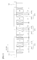
Fig. 1 is a vertical cross sectional view showing a configuration of a motor according to the present embodiment. -
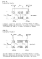
Fig. 2 is an explanatory view for explaining a coil arrangement configuration of a mover in the motor. -
Fig. 3 is an explanatory view for explaining an example of a coil configuration of prior arts. -
Fig. 4 is an explanatory view for explaining an example of a coil configuration of prior arts. -
Fig. 5 is an explanatory view for explaining an example of a coil configuration of prior arts. -
Fig. 6 is an explanatory view for explaining an example of a coil configuration of a comparative example. -
Fig. 7 is an explanatory view for explaining an example of a coil configuration of a comparative example. -
Fig. 8 is an explanatory view for explaining an example of a coil configuration of an embodiment. -
Fig. 9 is an explanatory view for explaining an example of a coil configuration of an embodiment. -
Fig. 10 is a graph showing a thrust-speed characteristic which is obtained by the motors of the prior arts and the embodiment. -
Fig. 11 is an explanatory view for explaining a coil arrangement configuration of a mover in a motor of a modified example. -
Fig. 12 is an explanatory view for explaining a coil arrangement configuration of a mover in a motor of a modified example - A description will be given below of an embodiment with reference to the accompanying drawings.
- A
motor 100 according to the present embodiment is a linear synchronous motor which employs three-phase alternating current.Fig. 1 shows a case that a slot combination of themotor 100 is 5-pole and 6-slot (5P6S) as an example. As shown inFig. 1 , themotor 100 has astator 110 and amover 120 which are arranged facing each other so as to be relatively movable via a magnetic air gap S. - The
stator 110 has atabular yoke 111, and a plurality ofpermanent magnets 112 arranged on theyoke 111 at a fixed interval (at a magnet pitch MP) in a relative movement direction. Themover 120 has acore 121, and amover base 122 made of resin, for example, and disposed so as to cover thecore 121. Thecore 121 is structured such that splitcores 125 each including ayoke 123 andteeth 124 disposed protruding from theyoke 123 to a magnetic air gap S side are arranged side by side at a fixed interval (at a teeth pitch TP) in a relative movement direction, andsub teeth 126 are arranged in both end portions of thesplit cores 125. In the present embodiment, thecore 121 is formed as the split configuration, however, may be formed into an integral configuration. - A plurality of
coils 127 is wound around each of slots which are formed between therespective teeth 124 of thecore 121. As shown inFig. 2 , in themotor 100 in which the slot combination is 5-pole and 6-slot (5P6S), two in-phase coils 127 are continuously arranged in the relative movement direction (a lateral direction inFig. 2 ). Reference symbols U, V and W shown inFig. 2 denote therespective coils 127 corresponding to a U phase, a V phase and a W phase, and thecoils 127 having opposite winding direction thereto are respectively shown by -U, -V and -W. - The
mover 120 has a coil group including two continuously arranged in-phase coils 127 for each phase (U phase, V phase, W phase). Thecoil group 127U corresponding to the U phase has a first coil 127U1 and a second coil 127U2 which are two in-phase (U-phase) coils continuously arranged in the relative movement direction. The first coil 127U1 is structured such that a coil width L1 is larger than a slot pitch SP (= teeth pitch TP), and the second coil 127U2 is structured such that a coil width L2 is smaller than the slot pitch SP. Further, wire diameters are the same in the first coil 127U1 and the second coil 127U2. The slot pitch SP is identical to a length in the relative movement direction of theyoke 123 in each of thesplit cores 125. - In the same manner, the
coil group 127V corresponding to the V phase has a first coil 127V1 and a second coil 127V2 which are continuously arranged in the relative movement direction, are in-phase (V-phase) coils and have the same wire diameter. The first coil 127V1 is structured such that a coil width L1 is larger than the slot pitch SP, and the second coil 127V2 is structured such that a coil width L2 is smaller than the slot pitch SP. Further, in the same manner, thecoil group 127W corresponding to the W phase has a first coil 127W1 and a second coil 127W2 which are continuously arranged in the relative movement direction, are in-phase (W-phase) coils and have the same wire diameter. The first coil 127W1 is structured such that a coil width L1 is larger than the slot pitch SP, and the second coil 127W2 is structured such that a coil width L2 is smaller than the slot pitch SP. - Sum of the coil width L1 of the first coil and the coil width L2 of the second coil in each phase approximately coincides with twice the slot pitch SP. According to the configuration mentioned above, an arrangement relationship of the coil width in the case that the
coil groups Fig. 2 , and thecoils 127 can be arranged with no gap in each phase. Therefore, since it is possible to prevent a space factor of the coil from being lowered, it is possible to prevent a motor constant from being lowered. - As shown in
Fig. 1 , themotor 100 has three sets ofcoil groups Fig. 2 in the relative movement direction, but the number of sets is not limited to this. Further, the example is structured such that themover 120 has thecoil groups coil groups - The greatest feature of the motor having the configuration mentioned above exists in a point that the
motor 100 has the first coils 127U1, 127V1, 127W1 in which the coil width L1 is larger than the slot pitch SP (= teeth pitch TP). A description will be given below of an effect obtained by the feature while using comparative examples. - In a poly-phase AC motor employing three-phase alternating current, in order to obtain an output characteristic (a thrust-speed characteristic) corresponding to demand of user, it is necessary to set a number of turns of the coil in each phase to an appropriate value. However, the motor of the prior arts has a problem that the number of turns of the coil jumps greatly. For example, as shown in
Fig. 3 , in a motor having a slot combination (5P6S) in which two in-phase coils are continuously arranged, for example, in the case that a height of the slot is set to 30 mm, and a width of the slot (a gap between the adjacent teeth) is set to 6 mm, the number of turns of each coil is 10 layers x 1 row (10 turns) in wire diameter φD = 3 mm, and a total number of turns N of one phase group = 10 turns x 2 coils = 20 turns is achieved. - In the case that the number of turns is increased under a condition that the space factor is approximately fixed, the number of turns in each coil is 20 layers x 2 rows (40 turns), and the total number of turns N of one phase group = 40 turns x 2 coils = 80 turns is achieved, for example, in the wire diameter φD = 1.5 mm as shown in
Fig. 4 . Further, the number of turns in each coil is 30 layers x 3 rows (90 turns), and the total number of turns N of one phase group = 90 turns x 2 coils = 180 turns is achieved, for example, in the wire diameter φD = 1 mm as shown inFig. 5 . As mentioned above, the number of turns N becomes four times and nine times as the wire diameter φD becomes smaller and the jumping amount becomes greater. Therefore, it is hard to set to the number of turns which corresponds to the demand of the user. - Accordingly, thinking about a case that an intermediate number of turns is obtained by changing the wire diameters and the numbers of turns of two in-phase coils. Configurations of this case will be shown in
Figs. 6 and 7 as the comparative examples. For example, as shown inFig. 6 , in the case of the wire diameter φD1 of the first coil (the coil in a left side ofFig. 6 ) = 3 mm, and the wire diameter φD2 of the second coil (the coil in a right side ofFig. 6 ) = 1.5 mm, the number of turns N1 of the first coil is 10 layers x 1 row (10 turns), the number of turns N2 of the second coil is 20 layers x 2 rows (40 turns), and the total number of turns N = 10 turns + 40turns = 50 turns is achieved. Further, for example, as shown inFig. 7 , in the case of the wire diameter φD1 of the first coil (the coil in a left side ofFig. 7 ) = 1.5 mm, and the wire diameter φD2 of the second coil (the coil in a right side ofFig. 7 ) = 1 mm, the number of turns N1 of the first coil is 20 layers x 2 rows (40 turns), the number of turns N2 of the second coil is 30 layers x 3 rows (90 turns), and the total number of turns N = 40 turns + 90 turns = 130 turns is achieved. As mentioned above, an intermediate number of turns can be obtained. However, since the wire diameters are different for each coil, it is impossible to wind the continuous in-phase coil with a single stroke, and there is a problem that productivity is lowered. - Consequently, the inventors of the present application have devoted themselves to research and develop in consideration of the matter that the wire diameter of the coil is restricted and has a reduced option (for example, in the above example, only the wire diameter φD = 3 mm, 1.5 mm and 1 mm can be selected in the range of 1 mm ≤φD ≤ 3 mm). As a result, the inventors of the present application have derived overriding of the technical common sense that the coils are designed so that the coil width L of each coil is within the slot pitch SP, and have derived a configuration according to the present embodiment for the first time. In other words, the present embodiment is structured, as mentioned above, such that the in-
phase coil groups - As a result, for example, in the example mentioned above, it is possible to further select the coil having the wire diameter φD = 2 mm or φD = 1.2 mm, and it is possible to increase the options of the wire diameter of the coil. As a result, in the case of the wire diameter φD = 2 mm as shown in
Fig. 8 , for example, the number of turns N1 of the first coil (the coil in a left side ofFig. 8 ) is 15 layers x 2 rows (30 turns), the number of turns N2 of the second coil (the coil in a right side ofFig. 8 ) is 15 layers x 1 row (15 turns), and the total number of turns N = 30 turns + 15 turns = 45 turns is achieved. Further, as shown inFig. 9 , in the case of the wire diameter φD = 1.2 mm, for example, the number of turns N1 of the first coil (the coil in a left side ofFig. 9 ) is 25 layers x 3 rows (75 turns), the number of turns N2 of the second coil (the coil in a right side ofFig. 9 ) is 25 layers x 2 row (50 turns), and the total number of turns N = 75 turns + 50 turns = 125 turns is achieved. Since an intermediate number of turns can be obtained as mentioned above, it is possible to increase the degree of freedom of the number of turns of the coil. Further, since the wire diameter φD can be made identical between the first and second coils, it is possible to wind the continuous in-phase coil with a single stroke, and it is possible to improve productivity. - As a result of the above, according to the present embodiment, since it is possible to obtain an intermediate output characteristic (thrust-speed characteristic) as shown in
Fig. 10 , it is possible to obtain an output characteristic which corresponds to the demand of the user. - Further, the present embodiment particularly has an effect that the space factor of the coil can be prevented from being lowered and the motor constant can be prevented from being lowered, in comparison with the case of application to a motor mentioned later in which three in-phase coils are continuously arranged, by application to the
motor 100 of a slot combination in which two in-phase coils are continuously arranged. - The first and second coils mentioned in
Figs. 6 and 7 do not correspond to the first and second coils described in claims, but the first and second coils mentioned inFigs. 2 ,8 and 9 correspond to the first and second coils described in claims. - In the embodiment mentioned above, the description is given of the case that the slot combination is 5-pole and 6-slot (5P6S) as an example, but the slot combination is not limited to this. As the slot combination in which two in-phase coils are arranged, there are additionally, for example, a slot combination of 7-pole and 6-slot (7P6S), a slot combination of 10-pole and 12-slot (10P12S) and a slot combination of 14-pole and 12-slot (14P12S), and the present disclosure can be applied to these motors.
- Further, it is possible to apply to a motor having a slot combination in which three in-phase coils are continuously arranged, without being limited to the motor in which two in-phase coils are continuously arranged. As the slot combination in which three in-phase coils are continuously arranged, there are, for example, a slot combination of 8-pole and 9-slot (8P9S) and a slot combination of 10-pole and 9-slot (10P9S). A description will be given of the present modified example with reference to
Figs. 11 and12 . - As shown in
Fig. 11 , in a motor according to the present modified example, three in-phase coils 127 are continuously arranged in a relative movement direction (a lateral direction inFig. 11 ). Amover 120 has a coil group including three continuously arranged in-phase coils 127 for each phase (U phase, V phase, W phase). Acoil group 127U corresponding to the U phase has a first coil 127U1 and two second coils 127U2 which are three in-phase (U-phase) coils continuously arranged in the relative movement direction. A coil width L1 of the first coil 127U1 is larger than a slot pitch SP (= teeth pitch TP), the second coils 127U2 are respectively positioned on both sides of the first coil 127U1 in the relative movement direction, and a coil width L2 of the second coils 127U2 is smaller than the slot pitch SP. Further, the first coil 127U1 and two second coils 127U2 have the same wire diameter, and can be wound with a single stroke. - A
coil group 127V corresponding to the V phase and acoil group 127W corresponding to the W phase also have the same configuration as that of thecoil group 127U. - In the motor in which thee in-phase coils are continuously arranged, like the present modified example, for example, in the case that the first coils 127U1, 127V1, 127W1 each having the coil width L1 larger than the slot pitch SP are respectively arranged on both sides in the relative movement direction of the second coils 127U2, 127V2, 127W2 each having the coil width L2 smaller than the slot pitch SP, an arrangement relationship of the coil widths in the case that the
coil groups - On the contrary, by respectively arranging two second coils 127U2, 127V2, 127W2 each having the coil width L2 which is smaller than the slot pitch SP on both sides in the relative movement direction of the first coils 127U1, 127V1, 127W1 each having the coil width L1 which is larger than the slot pitch SP, as shown in
Fig. 11 , the arrangement relationship of the coil widths in the case that thecoil groups - Further, in a
motor 100 shown inFig. 12 , acoil group 127U corresponding to the U phase has a first coil 127U1 in which a coil width L1 is larger than the slot pitch SP, and two second coils 127U2 which are arranged on one side in a relative movement direction of the first coil 127U1 (a right side inFig. 12 in this example, in which a left side inFig. 12 may be employed), and have coil widths L2 smaller than the slot pitch SP. The first coil 127U1 and two second coils 127U2 have the same wire diameter, and can be wound with a single stroke. Further, acoil group 127V corresponding to the V phase and acoil group 127W corresponding to the W phase have the same configuration as thecoil group 127U. - According to the present modified example, an arrangement relationship of the coil widths in the case that the
coil groups - The description is given above of the case that the
motor 100 is the linear synchronous motor as an example, but the present disclosure can be applied to a linear induction motor without being limited to this. Further, the present disclosure may be applied to a rotary type motor without being limited to the linear motor. - Further, it is possible to appropriately combine and utilize the techniques according to the embodiment and the respective modified example, in addition to the previously mentioned structures.
- In addition, the present invention can be executed by applying various changes within the range which does not deviate from the scope of the invention, although every change is not exemplified.
-
- 100
- motor
- 110
- stator
- 120
- mover
- 123
- yoke
- 124
- teeth
- 127
- coil
- 127
- U, V, W coil group
- 127
- U1, V1, W1 first coil
- 127
- U2, V2, W2 second coil
- L1, L2
- coil width
- S
- magnetic air gap
- TP
- teeth pitch
Claims (5)
- A motor comprising a stator and a mover which are arranged facing each other so as to be relatively movable via a magnetic air gap, characterized in that:any one of the stator and the mover includes:a yoke;a plurality of teeth disposed protruding from the yoke to the magnetic air gap side; anda plurality of coils wound around the plurality of teeth;the plurality of coils include, for each phase, coil groups each including a plurality of the coils which are continuously arranged along the relative movement direction and are in-phase with each other and have the same wire diameter with each other, andthe coil group comprises at least one the coil in which a coil width in the relative movement direction is larger than a teeth pitch in the relative movement direction.
- The motor according to claim 1, wherein:the coil group comprises two of the coils which are continuously arranged along the relative movement direction and are in-phase with each other and have the same wire diameter with each other, andthe two coils are a first coil in which the coil width is larger than the teeth pitch, and a second coil in which the coil width is smaller than the teeth pitch.
- The motor according to claim 2, wherein:sum of the coil widths of the first coil and the coil widths of the second coil approximately coincides with twice the teeth pitch.
- The motor according to claim 1, wherein:the coil group comprises three of the coils which are continuously arranged along the relative movement direction and are in-phase with each other and have the same wire diameter with each other, andthe three coils are a first coil in which the coil width is larger than the teeth pitch, and two second coils which are positioned on both sides of the first coil in the relative movement direction, and in which the coil width is smaller than the teeth pitch.
- The motor according to claim 1, wherein:the coil group comprises three of the coils which are continuously arranged along the relative movement direction and are in-phase with each other and have the same wire diameter with each other, andthe three coils are a first coil in which the coil width is larger than the teeth pitch, and two second coils which are positioned on one side of the first coil in the relative movement direction, and in which the coil width is smaller than the teeth pitch.
Applications Claiming Priority (1)
| Application Number | Priority Date | Filing Date | Title |
|---|---|---|---|
| PCT/JP2011/080243 WO2013098949A1 (en) | 2011-12-27 | 2011-12-27 | Motor |
Publications (2)
| Publication Number | Publication Date |
|---|---|
| EP2800247A1 true EP2800247A1 (en) | 2014-11-05 |
| EP2800247A4 EP2800247A4 (en) | 2015-09-02 |
Family
ID=48696517
Family Applications (1)
| Application Number | Title | Priority Date | Filing Date |
|---|---|---|---|
| EP11878688.8A Withdrawn EP2800247A4 (en) | 2011-12-27 | 2011-12-27 | ENGINE |
Country Status (6)
| Country | Link |
|---|---|
| US (1) | US9172281B2 (en) |
| EP (1) | EP2800247A4 (en) |
| JP (1) | JP5293984B1 (en) |
| KR (1) | KR101604936B1 (en) |
| CN (1) | CN104011976B (en) |
| WO (1) | WO2013098949A1 (en) |
Families Citing this family (8)
| Publication number | Priority date | Publication date | Assignee | Title |
|---|---|---|---|---|
| CN105515334A (en) * | 2015-12-18 | 2016-04-20 | 杨超 | Three-phase permanent-magnet linear motor octupole nine-slot stator winding |
| DE202016008461U1 (en) * | 2016-11-03 | 2018-01-22 | Brose Fahrzeugteile GmbH & Co. Kommanditgesellschaft, Würzburg | Stator of an electric motor and electric motor |
| US10734876B2 (en) * | 2018-03-19 | 2020-08-04 | Denso International America, Inc. | Brushless motor for HVAC system |
| CN108616207A (en) * | 2018-05-09 | 2018-10-02 | 同济大学 | A kind of long-stator linear motor winding for rail traffic |
| CN108599409A (en) * | 2018-06-19 | 2018-09-28 | 珠海凌达压缩机有限公司 | Motor winding, stator and synchronous motor |
| CN110190726A (en) * | 2019-05-30 | 2019-08-30 | 西南交通大学 | Mover, Unequal Pole Pitch Double-fed Linear Motor and Its Design Method |
| KR102761667B1 (en) * | 2019-11-06 | 2025-02-05 | 주식회사 코베리 | Linear motor and transfer system using the same |
| CN118435504B (en) * | 2022-04-08 | 2025-06-27 | 三菱电机株式会社 | Modular Linear Motor |
Family Cites Families (14)
| Publication number | Priority date | Publication date | Assignee | Title |
|---|---|---|---|---|
| US2394075A (en) * | 1941-02-26 | 1946-02-05 | Westinghouse Electric Corp | Generator and power plant therefor |
| US3466480A (en) * | 1967-04-14 | 1969-09-09 | Gen Electric | Commutation improvement for dynamoelectric machine |
| JPS5822575A (en) | 1981-08-03 | 1983-02-09 | Nippon Telegr & Teleph Corp <Ntt> | Cylindrical type linear induction motor for servomechanism |
| FR2726948B1 (en) * | 1994-11-16 | 1996-12-20 | Wavre Nicolas | PERMANENT MAGNET SYNCHRONOUS MOTOR |
| DE19740937A1 (en) * | 1997-09-17 | 1999-03-18 | Trw Fahrzeugelektrik | Procedure for winding stator for brushless DC motor e.g. for hydraulic power steering pump of vehicle |
| JP2004260985A (en) | 2003-02-03 | 2004-09-16 | Sankyo Seiki Mfg Co Ltd | Armature of rotary electric machine, rotary electric machine using the same, and method of manufacturing armature of rotary electric machine |
| JP4304999B2 (en) | 2003-02-14 | 2009-07-29 | 株式会社安川電機 | Three-phase armature winding and motor using the same |
| JP2005261117A (en) * | 2004-03-12 | 2005-09-22 | Honda Motor Co Ltd | Rotating electric machine |
| DE102006005046A1 (en) * | 2006-02-03 | 2007-08-09 | Siemens Ag | Electric machine with uneven pole teeth |
| DE102006035678A1 (en) * | 2006-07-31 | 2008-02-14 | Siemens Ag | Linear motor with force ripple compensation |
| DE102006061136A1 (en) * | 2006-12-22 | 2008-07-03 | Siemens Ag | short stroke |
| JP2008211918A (en) * | 2007-02-27 | 2008-09-11 | Kokusan Denki Co Ltd | Rotary electric machine |
| DE102008057349B3 (en) * | 2008-11-14 | 2010-07-15 | Feaam Gmbh | Electric machine |
| US8436504B2 (en) * | 2010-01-11 | 2013-05-07 | Ford Global Technologies, Llc | Stator for an electric machine |
-
2011
- 2011-12-27 KR KR1020147017684A patent/KR101604936B1/en active Active
- 2011-12-27 EP EP11878688.8A patent/EP2800247A4/en not_active Withdrawn
- 2011-12-27 CN CN201180075933.1A patent/CN104011976B/en active Active
- 2011-12-27 JP JP2012554550A patent/JP5293984B1/en active Active
- 2011-12-27 WO PCT/JP2011/080243 patent/WO2013098949A1/en not_active Ceased
-
2014
- 2014-06-24 US US14/312,694 patent/US9172281B2/en active Active
Also Published As
| Publication number | Publication date |
|---|---|
| WO2013098949A1 (en) | 2013-07-04 |
| US20140300212A1 (en) | 2014-10-09 |
| JPWO2013098949A1 (en) | 2015-04-30 |
| CN104011976A (en) | 2014-08-27 |
| US9172281B2 (en) | 2015-10-27 |
| CN104011976B (en) | 2016-08-24 |
| KR101604936B1 (en) | 2016-03-18 |
| JP5293984B1 (en) | 2013-09-18 |
| KR20140096389A (en) | 2014-08-05 |
| EP2800247A4 (en) | 2015-09-02 |
Similar Documents
| Publication | Publication Date | Title |
|---|---|---|
| US9172281B2 (en) | Motor | |
| US9793772B2 (en) | Stator for rotating electric machine | |
| US20130015742A1 (en) | Synchronous motor | |
| US20170324294A1 (en) | Wave Winding Having A Low Cogging Torque, Stator And Electric Machine Comprising A Wave Winding Of Said Type | |
| JP5574173B2 (en) | Permanent magnet type synchronous linear motor and table feeding device using the same | |
| EP3214733B1 (en) | Rotating electrical machine | |
| US20150222167A1 (en) | Linear Motor and Linear Motor Drive System | |
| CN104426315B (en) | Three-phase electromagnetic motor | |
| EP1999838B1 (en) | Single star connection winding arrangement for a rotating electrical machine | |
| WO2017110760A1 (en) | Rotating electrical machine and method of manufacturing same | |
| CN108736614B (en) | Stator of rotating electric machine | |
| JP2007259541A (en) | Permanent magnet motor | |
| KR101308154B1 (en) | Permanent magnet linear and rotating type synchronous motor | |
| US20140152140A1 (en) | Electric Machine And Method For Winding A Coil Of An Electric Machine | |
| CN215956131U (en) | Flat wire motor stator and motor | |
| JP5987789B2 (en) | Linear motor | |
| US11955864B2 (en) | Linear motor | |
| JP2006129546A (en) | Moving coil linear motor | |
| JP6582973B2 (en) | Rotating electric machine and manufacturing method thereof | |
| US20240048006A1 (en) | Stator for an electric machine, electric machine for driving a vehicle, and vehicle | |
| JP6610415B2 (en) | Three-phase synchronous machine and manufacturing method thereof | |
| JP4475059B2 (en) | Linear motor | |
| CN213637233U (en) | Motor stator and motor | |
| JP2518206B2 (en) | Winding method of brushless DC linear motor | |
| JP4710307B2 (en) | Hybrid pulse motor |
Legal Events
| Date | Code | Title | Description |
|---|---|---|---|
| PUAI | Public reference made under article 153(3) epc to a published international application that has entered the european phase |
Free format text: ORIGINAL CODE: 0009012 |
|
| 17P | Request for examination filed |
Effective date: 20140619 |
|
| AK | Designated contracting states |
Kind code of ref document: A1 Designated state(s): AL AT BE BG CH CY CZ DE DK EE ES FI FR GB GR HR HU IE IS IT LI LT LU LV MC MK MT NL NO PL PT RO RS SE SI SK SM TR |
|
| DAX | Request for extension of the european patent (deleted) | ||
| RA4 | Supplementary search report drawn up and despatched (corrected) |
Effective date: 20150731 |
|
| RIC1 | Information provided on ipc code assigned before grant |
Ipc: H02K 3/28 20060101ALI20150727BHEP Ipc: H02K 3/18 20060101AFI20150727BHEP Ipc: H02K 41/03 20060101ALI20150727BHEP |
|
| GRAP | Despatch of communication of intention to grant a patent |
Free format text: ORIGINAL CODE: EPIDOSNIGR1 |
|
| GRAJ | Information related to disapproval of communication of intention to grant by the applicant or resumption of examination proceedings by the epo deleted |
Free format text: ORIGINAL CODE: EPIDOSDIGR1 |
|
| STAA | Information on the status of an ep patent application or granted ep patent |
Free format text: STATUS: THE APPLICATION HAS BEEN WITHDRAWN |
|
| RIC1 | Information provided on ipc code assigned before grant |
Ipc: H02K 3/28 20060101ALI20160707BHEP Ipc: H02K 41/03 20060101ALI20160707BHEP Ipc: H02K 3/18 20060101AFI20160707BHEP |
|
| 18W | Application withdrawn |
Effective date: 20160719 |