EP2800169A1 - Battery cell assembly with improved safety, and battery module including same - Google Patents
Battery cell assembly with improved safety, and battery module including same Download PDFInfo
- Publication number
- EP2800169A1 EP2800169A1 EP20130755553 EP13755553A EP2800169A1 EP 2800169 A1 EP2800169 A1 EP 2800169A1 EP 20130755553 EP20130755553 EP 20130755553 EP 13755553 A EP13755553 A EP 13755553A EP 2800169 A1 EP2800169 A1 EP 2800169A1
- Authority
- EP
- European Patent Office
- Prior art keywords
- battery
- battery cells
- expansion opening
- opening parts
- assembly according
- Prior art date
- Legal status (The legal status is an assumption and is not a legal conclusion. Google has not performed a legal analysis and makes no representation as to the accuracy of the status listed.)
- Granted
Links
Images


Classifications
-
- H—ELECTRICITY
- H01—ELECTRIC ELEMENTS
- H01M—PROCESSES OR MEANS, e.g. BATTERIES, FOR THE DIRECT CONVERSION OF CHEMICAL ENERGY INTO ELECTRICAL ENERGY
- H01M50/00—Constructional details or processes of manufacture of the non-active parts of electrochemical cells other than fuel cells, e.g. hybrid cells
- H01M50/50—Current conducting connections for cells or batteries
- H01M50/572—Means for preventing undesired use or discharge
- H01M50/574—Devices or arrangements for the interruption of current
- H01M50/578—Devices or arrangements for the interruption of current in response to pressure
-
- H—ELECTRICITY
- H01—ELECTRIC ELEMENTS
- H01M—PROCESSES OR MEANS, e.g. BATTERIES, FOR THE DIRECT CONVERSION OF CHEMICAL ENERGY INTO ELECTRICAL ENERGY
- H01M50/00—Constructional details or processes of manufacture of the non-active parts of electrochemical cells other than fuel cells, e.g. hybrid cells
- H01M50/50—Current conducting connections for cells or batteries
- H01M50/528—Fixed electrical connections, i.e. not intended for disconnection
-
- B—PERFORMING OPERATIONS; TRANSPORTING
- B60—VEHICLES IN GENERAL
- B60L—PROPULSION OF ELECTRICALLY-PROPELLED VEHICLES; SUPPLYING ELECTRIC POWER FOR AUXILIARY EQUIPMENT OF ELECTRICALLY-PROPELLED VEHICLES; ELECTRODYNAMIC BRAKE SYSTEMS FOR VEHICLES IN GENERAL; MAGNETIC SUSPENSION OR LEVITATION FOR VEHICLES; MONITORING OPERATING VARIABLES OF ELECTRICALLY-PROPELLED VEHICLES; ELECTRIC SAFETY DEVICES FOR ELECTRICALLY-PROPELLED VEHICLES
- B60L3/00—Electric devices on electrically-propelled vehicles for safety purposes; Monitoring operating variables, e.g. speed, deceleration or energy consumption
- B60L3/0023—Detecting, eliminating, remedying or compensating for drive train abnormalities, e.g. failures within the drive train
- B60L3/0046—Detecting, eliminating, remedying or compensating for drive train abnormalities, e.g. failures within the drive train relating to electric energy storage systems, e.g. batteries or capacitors
-
- B—PERFORMING OPERATIONS; TRANSPORTING
- B60—VEHICLES IN GENERAL
- B60L—PROPULSION OF ELECTRICALLY-PROPELLED VEHICLES; SUPPLYING ELECTRIC POWER FOR AUXILIARY EQUIPMENT OF ELECTRICALLY-PROPELLED VEHICLES; ELECTRODYNAMIC BRAKE SYSTEMS FOR VEHICLES IN GENERAL; MAGNETIC SUSPENSION OR LEVITATION FOR VEHICLES; MONITORING OPERATING VARIABLES OF ELECTRICALLY-PROPELLED VEHICLES; ELECTRIC SAFETY DEVICES FOR ELECTRICALLY-PROPELLED VEHICLES
- B60L3/00—Electric devices on electrically-propelled vehicles for safety purposes; Monitoring operating variables, e.g. speed, deceleration or energy consumption
- B60L3/12—Recording operating variables ; Monitoring of operating variables
-
- B—PERFORMING OPERATIONS; TRANSPORTING
- B60—VEHICLES IN GENERAL
- B60L—PROPULSION OF ELECTRICALLY-PROPELLED VEHICLES; SUPPLYING ELECTRIC POWER FOR AUXILIARY EQUIPMENT OF ELECTRICALLY-PROPELLED VEHICLES; ELECTRODYNAMIC BRAKE SYSTEMS FOR VEHICLES IN GENERAL; MAGNETIC SUSPENSION OR LEVITATION FOR VEHICLES; MONITORING OPERATING VARIABLES OF ELECTRICALLY-PROPELLED VEHICLES; ELECTRIC SAFETY DEVICES FOR ELECTRICALLY-PROPELLED VEHICLES
- B60L50/00—Electric propulsion with power supplied within the vehicle
- B60L50/50—Electric propulsion with power supplied within the vehicle using propulsion power supplied by batteries or fuel cells
- B60L50/60—Electric propulsion with power supplied within the vehicle using propulsion power supplied by batteries or fuel cells using power supplied by batteries
- B60L50/64—Constructional details of batteries specially adapted for electric vehicles
-
- B—PERFORMING OPERATIONS; TRANSPORTING
- B60—VEHICLES IN GENERAL
- B60L—PROPULSION OF ELECTRICALLY-PROPELLED VEHICLES; SUPPLYING ELECTRIC POWER FOR AUXILIARY EQUIPMENT OF ELECTRICALLY-PROPELLED VEHICLES; ELECTRODYNAMIC BRAKE SYSTEMS FOR VEHICLES IN GENERAL; MAGNETIC SUSPENSION OR LEVITATION FOR VEHICLES; MONITORING OPERATING VARIABLES OF ELECTRICALLY-PROPELLED VEHICLES; ELECTRIC SAFETY DEVICES FOR ELECTRICALLY-PROPELLED VEHICLES
- B60L58/00—Methods or circuit arrangements for monitoring or controlling batteries or fuel cells, specially adapted for electric vehicles
- B60L58/10—Methods or circuit arrangements for monitoring or controlling batteries or fuel cells, specially adapted for electric vehicles for monitoring or controlling batteries
- B60L58/12—Methods or circuit arrangements for monitoring or controlling batteries or fuel cells, specially adapted for electric vehicles for monitoring or controlling batteries responding to state of charge [SoC]
- B60L58/14—Preventing excessive discharging
-
- B—PERFORMING OPERATIONS; TRANSPORTING
- B60—VEHICLES IN GENERAL
- B60L—PROPULSION OF ELECTRICALLY-PROPELLED VEHICLES; SUPPLYING ELECTRIC POWER FOR AUXILIARY EQUIPMENT OF ELECTRICALLY-PROPELLED VEHICLES; ELECTRODYNAMIC BRAKE SYSTEMS FOR VEHICLES IN GENERAL; MAGNETIC SUSPENSION OR LEVITATION FOR VEHICLES; MONITORING OPERATING VARIABLES OF ELECTRICALLY-PROPELLED VEHICLES; ELECTRIC SAFETY DEVICES FOR ELECTRICALLY-PROPELLED VEHICLES
- B60L58/00—Methods or circuit arrangements for monitoring or controlling batteries or fuel cells, specially adapted for electric vehicles
- B60L58/10—Methods or circuit arrangements for monitoring or controlling batteries or fuel cells, specially adapted for electric vehicles for monitoring or controlling batteries
- B60L58/12—Methods or circuit arrangements for monitoring or controlling batteries or fuel cells, specially adapted for electric vehicles for monitoring or controlling batteries responding to state of charge [SoC]
- B60L58/15—Preventing overcharging
-
- B—PERFORMING OPERATIONS; TRANSPORTING
- B60—VEHICLES IN GENERAL
- B60L—PROPULSION OF ELECTRICALLY-PROPELLED VEHICLES; SUPPLYING ELECTRIC POWER FOR AUXILIARY EQUIPMENT OF ELECTRICALLY-PROPELLED VEHICLES; ELECTRODYNAMIC BRAKE SYSTEMS FOR VEHICLES IN GENERAL; MAGNETIC SUSPENSION OR LEVITATION FOR VEHICLES; MONITORING OPERATING VARIABLES OF ELECTRICALLY-PROPELLED VEHICLES; ELECTRIC SAFETY DEVICES FOR ELECTRICALLY-PROPELLED VEHICLES
- B60L58/00—Methods or circuit arrangements for monitoring or controlling batteries or fuel cells, specially adapted for electric vehicles
- B60L58/10—Methods or circuit arrangements for monitoring or controlling batteries or fuel cells, specially adapted for electric vehicles for monitoring or controlling batteries
- B60L58/18—Methods or circuit arrangements for monitoring or controlling batteries or fuel cells, specially adapted for electric vehicles for monitoring or controlling batteries of two or more battery modules
-
- B—PERFORMING OPERATIONS; TRANSPORTING
- B60—VEHICLES IN GENERAL
- B60L—PROPULSION OF ELECTRICALLY-PROPELLED VEHICLES; SUPPLYING ELECTRIC POWER FOR AUXILIARY EQUIPMENT OF ELECTRICALLY-PROPELLED VEHICLES; ELECTRODYNAMIC BRAKE SYSTEMS FOR VEHICLES IN GENERAL; MAGNETIC SUSPENSION OR LEVITATION FOR VEHICLES; MONITORING OPERATING VARIABLES OF ELECTRICALLY-PROPELLED VEHICLES; ELECTRIC SAFETY DEVICES FOR ELECTRICALLY-PROPELLED VEHICLES
- B60L58/00—Methods or circuit arrangements for monitoring or controlling batteries or fuel cells, specially adapted for electric vehicles
- B60L58/10—Methods or circuit arrangements for monitoring or controlling batteries or fuel cells, specially adapted for electric vehicles for monitoring or controlling batteries
- B60L58/18—Methods or circuit arrangements for monitoring or controlling batteries or fuel cells, specially adapted for electric vehicles for monitoring or controlling batteries of two or more battery modules
- B60L58/21—Methods or circuit arrangements for monitoring or controlling batteries or fuel cells, specially adapted for electric vehicles for monitoring or controlling batteries of two or more battery modules having the same nominal voltage
-
- H—ELECTRICITY
- H01—ELECTRIC ELEMENTS
- H01M—PROCESSES OR MEANS, e.g. BATTERIES, FOR THE DIRECT CONVERSION OF CHEMICAL ENERGY INTO ELECTRICAL ENERGY
- H01M10/00—Secondary cells; Manufacture thereof
- H01M10/02—Details
-
- H—ELECTRICITY
- H01—ELECTRIC ELEMENTS
- H01M—PROCESSES OR MEANS, e.g. BATTERIES, FOR THE DIRECT CONVERSION OF CHEMICAL ENERGY INTO ELECTRICAL ENERGY
- H01M10/00—Secondary cells; Manufacture thereof
- H01M10/60—Heating or cooling; Temperature control
- H01M10/61—Types of temperature control
- H01M10/613—Cooling or keeping cold
-
- H—ELECTRICITY
- H01—ELECTRIC ELEMENTS
- H01M—PROCESSES OR MEANS, e.g. BATTERIES, FOR THE DIRECT CONVERSION OF CHEMICAL ENERGY INTO ELECTRICAL ENERGY
- H01M10/00—Secondary cells; Manufacture thereof
- H01M10/60—Heating or cooling; Temperature control
- H01M10/62—Heating or cooling; Temperature control specially adapted for specific applications
- H01M10/625—Vehicles
-
- H—ELECTRICITY
- H01—ELECTRIC ELEMENTS
- H01M—PROCESSES OR MEANS, e.g. BATTERIES, FOR THE DIRECT CONVERSION OF CHEMICAL ENERGY INTO ELECTRICAL ENERGY
- H01M10/00—Secondary cells; Manufacture thereof
- H01M10/60—Heating or cooling; Temperature control
- H01M10/64—Heating or cooling; Temperature control characterised by the shape of the cells
- H01M10/647—Prismatic or flat cells, e.g. pouch cells
-
- H—ELECTRICITY
- H01—ELECTRIC ELEMENTS
- H01M—PROCESSES OR MEANS, e.g. BATTERIES, FOR THE DIRECT CONVERSION OF CHEMICAL ENERGY INTO ELECTRICAL ENERGY
- H01M10/00—Secondary cells; Manufacture thereof
- H01M10/60—Heating or cooling; Temperature control
- H01M10/65—Means for temperature control structurally associated with the cells
- H01M10/655—Solid structures for heat exchange or heat conduction
- H01M10/6551—Surfaces specially adapted for heat dissipation or radiation, e.g. fins or coatings
-
- H—ELECTRICITY
- H01—ELECTRIC ELEMENTS
- H01M—PROCESSES OR MEANS, e.g. BATTERIES, FOR THE DIRECT CONVERSION OF CHEMICAL ENERGY INTO ELECTRICAL ENERGY
- H01M50/00—Constructional details or processes of manufacture of the non-active parts of electrochemical cells other than fuel cells, e.g. hybrid cells
- H01M50/10—Primary casings; Jackets or wrappings
- H01M50/102—Primary casings; Jackets or wrappings characterised by their shape or physical structure
- H01M50/105—Pouches or flexible bags
-
- H—ELECTRICITY
- H01—ELECTRIC ELEMENTS
- H01M—PROCESSES OR MEANS, e.g. BATTERIES, FOR THE DIRECT CONVERSION OF CHEMICAL ENERGY INTO ELECTRICAL ENERGY
- H01M50/00—Constructional details or processes of manufacture of the non-active parts of electrochemical cells other than fuel cells, e.g. hybrid cells
- H01M50/20—Mountings; Secondary casings or frames; Racks, modules or packs; Suspension devices; Shock absorbers; Transport or carrying devices; Holders
- H01M50/204—Racks, modules or packs for multiple batteries or multiple cells
- H01M50/207—Racks, modules or packs for multiple batteries or multiple cells characterised by their shape
- H01M50/211—Racks, modules or packs for multiple batteries or multiple cells characterised by their shape adapted for pouch cells
-
- H—ELECTRICITY
- H01—ELECTRIC ELEMENTS
- H01M—PROCESSES OR MEANS, e.g. BATTERIES, FOR THE DIRECT CONVERSION OF CHEMICAL ENERGY INTO ELECTRICAL ENERGY
- H01M50/00—Constructional details or processes of manufacture of the non-active parts of electrochemical cells other than fuel cells, e.g. hybrid cells
- H01M50/20—Mountings; Secondary casings or frames; Racks, modules or packs; Suspension devices; Shock absorbers; Transport or carrying devices; Holders
- H01M50/244—Secondary casings; Racks; Suspension devices; Carrying devices; Holders characterised by their mounting method
-
- H—ELECTRICITY
- H01—ELECTRIC ELEMENTS
- H01M—PROCESSES OR MEANS, e.g. BATTERIES, FOR THE DIRECT CONVERSION OF CHEMICAL ENERGY INTO ELECTRICAL ENERGY
- H01M50/00—Constructional details or processes of manufacture of the non-active parts of electrochemical cells other than fuel cells, e.g. hybrid cells
- H01M50/50—Current conducting connections for cells or batteries
- H01M50/502—Interconnectors for connecting terminals of adjacent batteries; Interconnectors for connecting cells outside a battery casing
- H01M50/505—Interconnectors for connecting terminals of adjacent batteries; Interconnectors for connecting cells outside a battery casing comprising a single busbar
-
- H—ELECTRICITY
- H01—ELECTRIC ELEMENTS
- H01M—PROCESSES OR MEANS, e.g. BATTERIES, FOR THE DIRECT CONVERSION OF CHEMICAL ENERGY INTO ELECTRICAL ENERGY
- H01M50/00—Constructional details or processes of manufacture of the non-active parts of electrochemical cells other than fuel cells, e.g. hybrid cells
- H01M50/50—Current conducting connections for cells or batteries
- H01M50/502—Interconnectors for connecting terminals of adjacent batteries; Interconnectors for connecting cells outside a battery casing
- H01M50/509—Interconnectors for connecting terminals of adjacent batteries; Interconnectors for connecting cells outside a battery casing characterised by the type of connection, e.g. mixed connections
-
- B—PERFORMING OPERATIONS; TRANSPORTING
- B60—VEHICLES IN GENERAL
- B60L—PROPULSION OF ELECTRICALLY-PROPELLED VEHICLES; SUPPLYING ELECTRIC POWER FOR AUXILIARY EQUIPMENT OF ELECTRICALLY-PROPELLED VEHICLES; ELECTRODYNAMIC BRAKE SYSTEMS FOR VEHICLES IN GENERAL; MAGNETIC SUSPENSION OR LEVITATION FOR VEHICLES; MONITORING OPERATING VARIABLES OF ELECTRICALLY-PROPELLED VEHICLES; ELECTRIC SAFETY DEVICES FOR ELECTRICALLY-PROPELLED VEHICLES
- B60L2240/00—Control parameters of input or output; Target parameters
- B60L2240/40—Drive Train control parameters
- B60L2240/54—Drive Train control parameters related to batteries
- B60L2240/545—Temperature
-
- B—PERFORMING OPERATIONS; TRANSPORTING
- B60—VEHICLES IN GENERAL
- B60L—PROPULSION OF ELECTRICALLY-PROPELLED VEHICLES; SUPPLYING ELECTRIC POWER FOR AUXILIARY EQUIPMENT OF ELECTRICALLY-PROPELLED VEHICLES; ELECTRODYNAMIC BRAKE SYSTEMS FOR VEHICLES IN GENERAL; MAGNETIC SUSPENSION OR LEVITATION FOR VEHICLES; MONITORING OPERATING VARIABLES OF ELECTRICALLY-PROPELLED VEHICLES; ELECTRIC SAFETY DEVICES FOR ELECTRICALLY-PROPELLED VEHICLES
- B60L2240/00—Control parameters of input or output; Target parameters
- B60L2240/40—Drive Train control parameters
- B60L2240/54—Drive Train control parameters related to batteries
- B60L2240/547—Voltage
-
- B—PERFORMING OPERATIONS; TRANSPORTING
- B60—VEHICLES IN GENERAL
- B60L—PROPULSION OF ELECTRICALLY-PROPELLED VEHICLES; SUPPLYING ELECTRIC POWER FOR AUXILIARY EQUIPMENT OF ELECTRICALLY-PROPELLED VEHICLES; ELECTRODYNAMIC BRAKE SYSTEMS FOR VEHICLES IN GENERAL; MAGNETIC SUSPENSION OR LEVITATION FOR VEHICLES; MONITORING OPERATING VARIABLES OF ELECTRICALLY-PROPELLED VEHICLES; ELECTRIC SAFETY DEVICES FOR ELECTRICALLY-PROPELLED VEHICLES
- B60L2240/00—Control parameters of input or output; Target parameters
- B60L2240/40—Drive Train control parameters
- B60L2240/54—Drive Train control parameters related to batteries
- B60L2240/549—Current
-
- H—ELECTRICITY
- H01—ELECTRIC ELEMENTS
- H01M—PROCESSES OR MEANS, e.g. BATTERIES, FOR THE DIRECT CONVERSION OF CHEMICAL ENERGY INTO ELECTRICAL ENERGY
- H01M2200/00—Safety devices for primary or secondary batteries
- H01M2200/20—Pressure-sensitive devices
-
- H—ELECTRICITY
- H01—ELECTRIC ELEMENTS
- H01M—PROCESSES OR MEANS, e.g. BATTERIES, FOR THE DIRECT CONVERSION OF CHEMICAL ENERGY INTO ELECTRICAL ENERGY
- H01M2220/00—Batteries for particular applications
- H01M2220/20—Batteries in motive systems, e.g. vehicle, ship, plane
-
- H—ELECTRICITY
- H01—ELECTRIC ELEMENTS
- H01M—PROCESSES OR MEANS, e.g. BATTERIES, FOR THE DIRECT CONVERSION OF CHEMICAL ENERGY INTO ELECTRICAL ENERGY
- H01M2220/00—Batteries for particular applications
- H01M2220/30—Batteries in portable systems, e.g. mobile phone, laptop
-
- Y—GENERAL TAGGING OF NEW TECHNOLOGICAL DEVELOPMENTS; GENERAL TAGGING OF CROSS-SECTIONAL TECHNOLOGIES SPANNING OVER SEVERAL SECTIONS OF THE IPC; TECHNICAL SUBJECTS COVERED BY FORMER USPC CROSS-REFERENCE ART COLLECTIONS [XRACs] AND DIGESTS
- Y02—TECHNOLOGIES OR APPLICATIONS FOR MITIGATION OR ADAPTATION AGAINST CLIMATE CHANGE
- Y02E—REDUCTION OF GREENHOUSE GAS [GHG] EMISSIONS, RELATED TO ENERGY GENERATION, TRANSMISSION OR DISTRIBUTION
- Y02E60/00—Enabling technologies; Technologies with a potential or indirect contribution to GHG emissions mitigation
- Y02E60/10—Energy storage using batteries
-
- Y—GENERAL TAGGING OF NEW TECHNOLOGICAL DEVELOPMENTS; GENERAL TAGGING OF CROSS-SECTIONAL TECHNOLOGIES SPANNING OVER SEVERAL SECTIONS OF THE IPC; TECHNICAL SUBJECTS COVERED BY FORMER USPC CROSS-REFERENCE ART COLLECTIONS [XRACs] AND DIGESTS
- Y02—TECHNOLOGIES OR APPLICATIONS FOR MITIGATION OR ADAPTATION AGAINST CLIMATE CHANGE
- Y02T—CLIMATE CHANGE MITIGATION TECHNOLOGIES RELATED TO TRANSPORTATION
- Y02T10/00—Road transport of goods or passengers
- Y02T10/60—Other road transportation technologies with climate change mitigation effect
- Y02T10/70—Energy storage systems for electromobility, e.g. batteries
Definitions
- a current interrupt device (CID) system which is mainly used as a method of interrupting electrical connection between a middle or large-sized battery pack and an external device when the middle or large-sized battery pack abnormally operates, is configured to operate only when the outermost battery modules or the outermost battery cells abnormally operate. In a case in which the outermost battery modules or the outermost battery cells normally operate, therefore, it is difficult to exhibit a desired effect.
- the inventors of the present application have found that, when expansion force generated in battery cells laterally stacked while being adjacent to each other due to swelling of the battery cells are applied to the battery cells in opposite directions in an abnormal operation state of a battery cell assembly with the result that an electrical connection region between the battery cells is ruptured, it is possible to increase force required to rupture the an electrical connection region between the battery cells while improving operational reliability and stability.
- the present invention has been completed based on these findings.
- a battery cell assembly including a plurality of battery cells stacked while being electrically connected to each other, wherein one or more of the battery cells are mounted in each cell housing member in a state in which opposite sides of the battery cells are surrounded by each cell housing member excluding electrode terminals of the battery cells, an expansion opening part, through which a portion of a main body of each of the battery cells is exposed outward when the battery cells expand, is formed at one surface or opposite surfaces of each of the at least two cell housing members and the battery cells are stacked such that the at least two expansion opening parts face each other.
- the battery cells are stacked such that the at least two expansion opening parts formed at one surface or opposite surfaces of the at least two cell housing members face each other.
- expansion force generated in the battery cells due to swelling of the battery cells to the battery cells in opposite direction such that the distance between the cell housing members is increased with the result that electrical connection between the battery cells mounted in the cell housing members stacked while being adjacent to each other may be ruptured.
- the electrical connection may be series connection or parallel connection as described below.
- the battery cells may be electrically connected to each other using various methods.
- the battery cells may be electrically connected in parallel to each other via a bus bar.
- the battery cells may be electrically connected in series to each other via an inter bus bar.
- the parallel connected battery cells i.e. the battery cells between the respective cell housing members
- the series connection may be achieved using the inter bus bar.
- a pair of the expansion opening parts facing each other and another adjacent pair of the expansion opening parts may be diagonally arranged or may face each other.
- each of the expansion opening parts may have various shapes.
- each of the expansion opening parts may be formed at each cell housing member in the shape of an opening, through which a portion of the main body of a corresponding one of the battery cells is exposed even in a state in which the battery cell does not expand.
- each of the expansion opening parts may be formed at each cell housing member in the shape of a notch configured to be ruptured when a corresponding one of the battery cells expands such that a portion of the main body of the battery cell is exposed.
- each of the expansion opening parts may have an area equivalent to 10 to 50% the total area of one surface of each cell housing member at a position of each cell housing member adjacent to an electrode terminal connection region between the battery cells.
- a battery pack including the battery module with the above-stated construction as an electric power source of a middle or large-sized device.
- the middle or large-sized device may be an electric means of transport, such as an electric vehicle (EV), a hybrid electric vehicle (HEV), or a plug-in hybrid electric vehicle (PHEV), or a power storage device.
- EV electric vehicle
- HEV hybrid electric vehicle
- PHEV plug-in hybrid electric vehicle
- the present invention is not limited thereto.
- the cell housing member includes a pair of a first housing 200a and a second housing 200b coupled to each other.
- the first housing 200a is provided at the outer surface thereof with protrusions 210a, 220a, 230a, and 250a to define a coolant channel, which are formed at a region of the first housing 200a excluding an expansion opening part 270.
- the second housing 200b is provided at the outer surface thereof with protrusions 210b, 220b, 230b, 240b, and 250b to define a coolant channel.
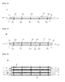
- a battery cell assembly 600 is configured to have a structure in which unit modules 400, 401, and 402, each of which is configured to have the same structure as a unit module of FIG. 3 including two or more battery cells mounted in a cell housing member, are stacked in a state in which the modules 400, 401, and 402 are connected in series to one another (510 and 520) such that expansion opening parts 270 and 271 face each other and protrusions are formed at the outer surfaces of the respective cell housings such that the protrusions correspond to each other excluding the expansion opening parts 270 and 271 to define a coolant channel among the stacked unit modules 400, 401, and 402.
- FIG. 7 is a side view typically showing another embodiment of a case in which battery cells abnormally operate.
- a cell housing member 400 is provided at an upper surface and a lower surface thereof with expansion opening parts 270 and 272, which are diagonally arranged.
- a cell housing member 402 is provided at an upper surface with an expansion opening part 273 and a cell housing member 401 is provided at a lower surface with an expansion opening part 271.
- the expansion opening parts 270 and 271 and the expansion opening parts 272 and 273 are diagonally arranged in a state in which the cell housing member 400 is between the expansion opening parts 270 and 271 and the expansion opening parts 272 and 273.
- the cell housing member 402 is the lowermost cell housing member.
- the cell housing member 402 is fixed to a module case (not shown).
- a cathode slurry was prepared by putting and mixing 95 weight percent of LiCoO 2 , 2.5 weight percent of Super-P, and 2.5 weight percent of PVdf in NMP.
- the cathode slurry was coated on an aluminum foil having a thickness of 20 ⁇ m such that the cathode slurry has a thickness of 200 ⁇ m, rolled, and dried to manufacture a cathode.
- An anode slurry was prepared by putting and mixing 96 weight percent of graphite, 1.5 weight percent of Super-P, and 2.5 weight percent of SBR/CMC in water.
- the anode slurry was coated on a copper foil having a thickness of 10 ⁇ m, rolled, and dried to manufacture an anode.
- pouch-shaped battery cells manufactured according to Example 1 were charged and discharged 100 times under a temperature condition of 45 °C, a charging condition of 1.0 C, and a discharging condition of 1.0 C.
- a plurality of unit modules was stacked in a state in which the unit modules were connected in series to each other to manufacture a battery cell assembly according to the present invention.
- An expansion opening part was formed at the lower surface of the uppermost unit module, an expansion opening part was formed at the upper surface of an adjacent unit module stacked under the uppermost unit module, and the unit modules were arranged such that the expansion opening parts faced each other.
- the uppermost unit module and the adjacent unit module stacked under the uppermost unit module were constituted by the pouch-shaped battery cells manufactured according to Example 2.
- the remaining unit modules excluding the uppermost battery cell and the uppermost unit module were constituted by the pouch-shaped battery cells manufactured according to Example 1.
- Two pouch-shaped battery cells were mounted in a cell housing member in a state in which the pouch-shaped battery cells were connected in parallel to each other to manufacture a unit module.
- a plurality of unit modules was stacked in a state in which the unit modules were connected in series to each other to manufacture a battery cell assembly according to the present invention.
- An expansion opening part was formed at the lower surface of the uppermost unit module and an expansion opening part was formed at the upper surface of the lowermost unit module.
- Expansion opening parts were formed at the upper surfaces and the lower surfaces of the remaining unit modules excluding the uppermost unit module and the lowermost unit module such that the expansion opening parts formed at the upper surfaces and the lower surfaces of the remaining unit modules were diagonally arranged.
- a pair of expansion opening parts facing each other and another adjacent pair of expansion opening parts were diagonally arranged.
- All of the unit modules were constituted by the pouch-shaped battery cells manufactured according to Example 2.
- Two pouch-shaped battery cells were mounted in a cell housing member in a state in which the pouch-shaped battery cells were connected in parallel to each other to manufacture a unit module.
- a plurality of unit modules was stacked in a state in which the unit modules were connected in series to each other to manufacture a battery cell assembly according to the present invention.
- An expansion opening part was formed at the lower surface of the uppermost unit module and an expansion opening part was formed at the upper surface of the lowermost unit module.
- Expansion opening parts were formed at the upper surfaces and the lower surfaces of the remaining unit modules excluding the uppermost unit module and the lowermost unit module such that the expansion opening parts formed at the upper surfaces and the lower surfaces of the remaining unit modules were diagonally arranged.
- a pair of expansion opening parts facing each other and another adjacent pair of expansion opening parts were diagonally arranged.
- One of the remaining unit modules excluding the uppermost unit module and the lowermost unit module was constituted by the pouch-shaped battery cells manufactured according to Example 2 and the other unit modules were constituted by the pouch-shaped battery cells manufactured according to Example 1.
- Two pouch-shaped battery cells were mounted in a cell housing member in a state in which the pouch-shaped battery cells were connected in parallel to each other to manufacture a unit module.
- a plurality of unit modules was stacked in a state in which the unit modules were connected in series to each other to manufacture a battery cell assembly according to the present invention.
- An expansion opening part was formed only at the upper surface of the uppermost unit module.
- the uppermost unit module and an adjacent unit module stacked under the uppermost unit module were constituted by the pouch-shaped battery cells manufactured according to Example 2.
- the remaining unit modules excluding the uppermost battery cell and the uppermost unit module were constituted by the pouch-shaped battery cells manufactured according to Example 1.
- Two pouch-shaped battery cells were mounted in a cell housing member in a state in which the pouch-shaped battery cells were connected in parallel to each other to manufacture a unit module.
- a plurality of unit modules was stacked in a state in which the unit modules were connected in series to each other to manufacture a battery cell assembly according to the present invention.
- An expansion opening part was formed only at the upper surface of the uppermost unit module.
- All of the unit modules were constituted by the pouch-shaped battery cells manufactured according to Example 2.
- Two pouch-shaped battery cells were mounted in a cell housing member in a state in which the pouch-shaped battery cells were connected in parallel to each other to manufacture a unit module.
- a plurality of unit modules was stacked in a state in which the unit modules were connected in series to each other to manufacture a battery cell assembly according to the present invention.
- An expansion opening part was formed only at the upper surface of the uppermost unit module.
- One of the remaining unit modules excluding the uppermost unit module and the lowermost unit module was constituted by the pouch-shaped battery cells manufactured according to Example 2 and the other unit modules were constituted by the pouch-shaped battery cells manufactured according to Example 1.
- Example 4 Upon comparison between Example 4 and Comparative example 2, it can be seen that the unit modules according to Comparative example 2 were not cut off because force to rupture the parallel connection between the battery cells constituting the uppermost unit module was low, whereas the unit modules according to Example 4 were cut off within a short time because expansion force of the battery cells was concentrated.
- Example 5 Upon comparison between Example 5 and Comparative example 3, it can be seen that safety of the battery cell assembly according to the present invention was secured even when any one of the battery cells constituting the remaining stacked unit modules excluding the outermost unit modules abnormally operated.
- a battery cell assembly according to the present invention is configured to have a structure in which an expansion opening part is formed at one surface or opposite surfaces of each of at least two cell housing members and battery cells are stacked such that the at least two expansion opening parts face each other.
- the cut-off effect due to rupture of the electrical connection is achieved by abnormal operation of the battery cells which are laterally stacked as well as abnormal operation of the battery cells mounted in the outermost unit modules, thereby achieving higher safety and operational reliability than in the conventional battery cell assembly.
Landscapes
- Engineering & Computer Science (AREA)
- Chemical Kinetics & Catalysis (AREA)
- Electrochemistry (AREA)
- General Chemical & Material Sciences (AREA)
- Chemical & Material Sciences (AREA)
- Power Engineering (AREA)
- Life Sciences & Earth Sciences (AREA)
- Sustainable Energy (AREA)
- Sustainable Development (AREA)
- Transportation (AREA)
- Mechanical Engineering (AREA)
- Manufacturing & Machinery (AREA)
- Battery Mounting, Suspending (AREA)
- Secondary Cells (AREA)
- Sealing Battery Cases Or Jackets (AREA)
- Connection Of Batteries Or Terminals (AREA)
Abstract
Description
- The present invention relates to a battery cell assembly with improved safety and a battery module including the same and, more particularly, to a battery cell assembly including a plurality of battery cells stacked while being electrically connected to each other, wherein one or more of the battery cells are mounted in each cell housing member in a state in which opposite sides of the battery cells are surrounded by each cell housing member excluding electrode terminals of the battery cells, an expansion opening part, through which a portion of a main body of each of the battery cells is exposed outward when the battery cells expand, is formed at one surface or opposite surfaces of each of the at least two cell housing members and the battery cells are stacked such that the at least two expansion opening parts face each other.
- Recently, a secondary battery, which can be charged and discharged, has been widely used as an energy source for wireless mobile devices. In addition, the secondary battery has attracted considerable attention as a power source for electric vehicles (EV), hybrid electric vehicles (HEV), and plug-in hybrid electric vehicles (Plug-In HEV), which have been developed to solve problems, such as air pollution, caused by existing gasoline and diesel vehicles using fossil fuels or as a power storage device to store surplus power such that the power can be used as needed.
- Small-sized mobile devices use one or several battery cells for each device. On the other hand, middle or large-sized devices, such as vehicles, use a battery module having a plurality of battery cells electrically connected to each other because high output and large capacity are necessary for the middle or large-sized devices.
- Preferably, the battery module is manufactured so as to have as small a size and weight as possible. For this reason, a prismatic battery or a pouch-shaped battery, which can be stacked with high integration and has a small weight to capacity ratio, is usually used as a battery cell of the middle or large-sized battery module. In particular, much interest is currently focused on such a pouch-shaped battery, which uses an aluminum laminate sheet as a sheathing member, because the pouch-shaped battery is lightweight and the manufacturing cost of the pouch-shaped battery is low.
- Meanwhile, the battery module is configured to have a structure in which a plurality of battery cells is combined. In a case in which some of the battery cells are overcharged or overdischarged, therefore, a large amount of gas is generated due to decomposition of an electrolyte with the result that a battery case of each of the battery cells swells, i.e. a so-called swelling phenomenon occurs. The swelling phenomenon further accelerates decomposition of the electrolyte while causing high pressure in the sealed battery case with the result that the battery module may explode. Furthermore, abnormal operation of some of the battery cells may cause abnormal operation of the other battery cells with the result that a fire or explosion of the battery module may occur, which may lead to a large-scale accident.
- For this reason, the secondary battery is provided with a safety system, such as a protection circuit to interrupt electric current when the secondary battery is overcharged or overdischarged or when overcurrent flows in the secondary battery, a positive temperature coefficient (PTC) element whose resistance greatly increases so as to interrupt electric current when the temperature of the secondary battery increases, or a safety vent to interrupt electric current or to exhaust gas when pressure increases due to generation of the gas. On the other hand, a multi cell type middle or large-sized battery pack, which is configured to have a multi cell structure in which a plurality of battery modules is combined, is provided with a safety system, such as a fuse, a bimetal, or a battery management system (BMS), to protect battery cells from overcharge, overdischarge, or overcurrent.
- However, the safety system, such as the PTC element or the BMS, may malfunction. On the other hand, a current interrupt device (CID) system, which is mainly used as a method of interrupting electrical connection between a middle or large-sized battery pack and an external device when the middle or large-sized battery pack abnormally operates, is configured to operate only when the outermost battery modules or the outermost battery cells abnormally operate. In a case in which the outermost battery modules or the outermost battery cells normally operate, therefore, it is difficult to exhibit a desired effect.
- In addition, it is necessary to inevitably provide a space through which the battery modules or the battery cells are partially exposed to the outside even in a case in which the outermost battery modules or the outermost battery cells swell with the result that it is difficult to increase the capacity per volume.
- Consequently, there is a high necessity for a battery cell assembly configured to have a novel structure that is capable of fundamentally securing safety of the battery module and the battery pack while solving the above problems.
- Therefore, the present invention has been made to solve the above problems and other technical problems that have yet to be resolved.
- As a result of a variety of extensive and intensive studies and experiments to solve the problems as described above, the inventors of the present application have found that, when expansion force generated in battery cells laterally stacked while being adjacent to each other due to swelling of the battery cells are applied to the battery cells in opposite directions in an abnormal operation state of a battery cell assembly with the result that an electrical connection region between the battery cells is ruptured, it is possible to increase force required to rupture the an electrical connection region between the battery cells while improving operational reliability and stability. The present invention has been completed based on these findings.
- In accordance with one aspect of the present invention, the above and other objects can be accomplished by the provision of a battery cell assembly including a plurality of battery cells stacked while being electrically connected to each other, wherein one or more of the battery cells are mounted in each cell housing member in a state in which opposite sides of the battery cells are surrounded by each cell housing member excluding electrode terminals of the battery cells, an expansion opening part, through which a portion of a main body of each of the battery cells is exposed outward when the battery cells expand, is formed at one surface or opposite surfaces of each of the at least two cell housing members and the battery cells are stacked such that the at least two expansion opening parts face each other.
- In the battery cell assembly according to the present invention, the battery cells are stacked such that the at least two expansion opening parts formed at one surface or opposite surfaces of the at least two cell housing members face each other. In a case in which one or more battery cells mounted in each cell housing member abnormally operate and a portion of the main body of each of the battery cells is exposed outward through a corresponding one of the expansion opening parts, therefore, expansion force generated in the battery cells due to swelling of the battery cells to the battery cells in opposite direction such that the distance between the cell housing members is increased with the result that electrical connection between the battery cells mounted in the cell housing members stacked while being adjacent to each other may be ruptured. The electrical connection may be series connection or parallel connection as described below.
- As previously described, abnormal operation of some of the battery cells may cause abnormal operation of the other battery cells. As a result, the cut-off effect of the electrical connection is successively achieved between the battery cells mounted in the cell housing members stacked while being adjacent to each other. Consequently, the battery cell assembly according to the present invention has higher safety and operational reliability than the conventional battery cell assembly.
- As described above, one battery cell may be mounted in each cell housing member. On the other hand, two or more battery cells may be mounted in each cell housing member. A battery cell assembly configured to have a structure in which two or more battery cells may be mounted in a cell housing member may be referred to as a unit module.
- The battery cells may be electrically connected to each other using various methods. For example, the battery cells may be electrically connected in parallel to each other via a bus bar. On the other hand, the battery cells may be electrically connected in series to each other via an inter bus bar.
- In a case in which one battery cell is mounted in each cell housing member, the battery cells may be configured to have a structure in which the battery cells are stacked while being connected in series to each other via the inter bus bar. Of course, the battery cells may be configured to have a structure in which the battery cells are stacked while being connected in parallel to each other via the bus bar.
- In a case in which the battery cells are stacked while being connected in parallel to each other, however, the parallel connected battery cells, i.e. the battery cells between the respective cell housing members, may be connected in series to each other. The series connection may be achieved using the inter bus bar.
- On the other hand, in a case in which two or more battery cells are mounted in each cell housing member, the battery cells may be connected in series or in parallel to each other. In addition, the battery cells between the respective cell housing members may be connected in parallel or in series to each other.
- In a concrete example of the present invention, the battery cells mounted in each cell housing member may be connected in parallel to each other via the bus bar and the battery cells between the respective cell housing members may be connected in series to each other via the inter bus bar.
- In an abnormal operation state of the battery cells, expansion force generated due to swelling of the battery cells is concentrated on the expansion opening parts. As a result, the inter bus bar or the bus bar and the inter bus bar may be ruptured, whereby the battery cell assembly is cut off.
- In connection with this case, the inventors of the present application have found that, in a case in which the battery cells are connected in series and in parallel to each other as described above, it is difficult to simultaneously rupture the series connection region and the parallel connection region only using expansion force generated due to swelling of the battery cells applied in one direction while having a magnitude to rupture the series connection region of the outermost battery modules or the outermost battery cells. On the other hand, in a case in which the battery cells are connected in series and in parallel to each other, the battery cell assembly according to the present invention exhibits higher safety and operational reliability than the conventional battery cell assembly.
- The expansion opening parts may be formed at opposite surfaces of some or all of the other ones of the cell housing members excluding the uppermost and lowermost ones of the cell housing members. Preferably, the expansion opening parts are formed at opposite surfaces of all of the other ones of the cell housing members excluding the uppermost and lowermost ones of the cell housing members.
- In this case, one of the expansion opening parts may be formed at a lower surface of the uppermost one of the cell housing members and one of the expansion opening parts may be formed at an upper surface of a lowermost one of the cell housing members. The expansion opening parts formed at the opposite surfaces of the cell housing members, i.e. the expansion opening part formed at the upper surface (or the lower surface) of the cell housing member and the expansion opening part formed at the lower surface (or the upper surface) of the cell housing member, may be diagonally arranged. On the other hand, the expansion opening part formed at the upper surface (or the lower surface) of the cell housing member and the expansion opening part formed at the lower surface (or the upper surface) of the cell housing member, may face each other.
- A pair of the expansion opening parts facing each other and another adjacent pair of the expansion opening parts may be diagonally arranged or may face each other.
- In this specification, the upper surface and the lower surface of the cell housing member illustratively refer to one surface and the other corresponding surface of the cell housing member. That is, the upper surface and the lower surface of the cell housing member are not restrictive.
- Each of the expansion opening parts may have various shapes. For example, each of the expansion opening parts may be formed at each cell housing member in the shape of an opening, through which a portion of the main body of a corresponding one of the battery cells is exposed even in a state in which the battery cell does not expand. On the other hand, each of the expansion opening parts may be formed at each cell housing member in the shape of a notch configured to be ruptured when a corresponding one of the battery cells expands such that a portion of the main body of the battery cell is exposed.
- Even in any of the above cases, each of the expansion opening parts may be formed at a position of each cell housing member adjacent to an electrode terminal connection region between the battery cells such that the electrode terminal connection region, i.e. the bus bar or the inter bus bar, is ruptured when the battery cells expand and, therefore, the battery cell assembly is cut off. Specifically, each of the expansion opening parts may be formed at one side part of each cell housing member adjacent to the electrode terminal connection region.
- In this case, each of the expansion opening parts may have an area equivalent to 10 to 50% the total area of one surface of each cell housing member at a position of each cell housing member adjacent to an electrode terminal connection region between the battery cells.
- The expression "each of the expansion opening parts may have an area equivalent to 50% the total area of one surface of each cell housing member" may mean that the expansion opening part is formed at the entirety of one side part, e.g. the left side part or the right side part, of the cell housing member in the shape of an opening.
- Each of the battery cells may be a battery cell configured to have a structure in which an electrode assembly is mounted in a battery case formed of a laminate sheet comprising a metal layer and a resin layer and the battery case is thermally bonded along an outer circumference of an electrode assembly receiving unit to form a sealed portion, i.e. a so-called a pouch-shaped battery cell. Each cell housing member may include a pair of a first housing and a second housing coupled to each other.
- The first housing of a first one of the battery cells and the second housing of a second one of the battery cells constituting a stacked structure together with the first one of the battery cells may be provided at outer surfaces thereof with protrusions to define coolant channels formed at regions of the first housing and the second housing excluding the expansion opening parts. In this case, the protrusions may be formed at corresponding positions.
- Each of the battery cells may be used as an electric power source for small-sized devices. In addition, each of the battery cells may be used as a unit battery of a middle or large-sized battery module including a plurality of battery cells, i.e. a battery cell assembly.
- In accordance with another aspect of the present invention, there is provided a battery pack including the battery module with the above-stated construction as an electric power source of a middle or large-sized device. The middle or large-sized device may be an electric means of transport, such as an electric vehicle (EV), a hybrid electric vehicle (HEV), or a plug-in hybrid electric vehicle (PHEV), or a power storage device. However, the present invention is not limited thereto.
- The structure and a manufacturing method of the middle or large-sized device are well known in the art to which the present invention pertains and, therefore, a detailed description thereof will be omitted.
- The above and other objects, features and other advantages of the present invention will be more clearly understood from the following detailed description taken in conjunction with the accompanying drawings, in which:
-
FIG. 1 is a plan view showing a battery cell mounted in a cell housing member according to an embodiment of the present invention; -
FIG. 2 is a rear view showing the battery cell mounted in the cell housing member according to the embodiment of the present invention; -
FIG. 3 is a side view typically showing a unit module configured to have a structure in which two battery cells are mounted in a cell housing member according to an embodiment of the present invention; -
FIG. 4 is a side view typically showing a case in which the battery cells abnormally operate in the unit module structure shown inFIG. 3 ; -
FIG. 5 is a side view typically showing a structure in which unit modules, one of which is shown inFIG. 3 , are stacked such that expansion opening parts of the unit modules faces each other; -
FIG. 6 is a side view typically showing a case in which the battery cells abnormally operate in the structure shown inFIG. 5 ; and -
FIG. 7 is a side view typically showing a case in which battery cells abnormally operate in another structure in which unit modules are stacked. - Now, preferred embodiments of the present invention will be described in detail with reference to the accompanying drawings. It should be noted, however, that the scope of the present invention is not limited by the illustrated embodiments.
-
FIG. 1 is a plan view showing a battery cell mounted in a cell housing member according to an embodiment of the present invention andFIG. 2 is a rear view showing the battery cell mounted in the cell housing member according to the embodiment of the present invention. - Referring to
FIGS. 1 and 2 , opposite sides of abattery cell 100 havingelectrode terminals first housing 200a and asecond housing 200b coupled to each other. Thefirst housing 200a is provided at the outer surface thereof withprotrusions first housing 200a excluding anexpansion opening part 270. Thesecond housing 200b is provided at the outer surface thereof withprotrusions - The
expansion opening part 270 is formed in the shape of an opening, through which a portion of a main body of thebattery cell 100 is exposed even when thebattery cell 100 does not expand. Theexpansion opening part 270 has an area equivalent to about 40% the total area of the cell housing member. Theexpansion opening part 270 is formed at the right side part of the cell housing member. -
FIG. 3 is a side view typically showing a unit module configured to have a structure in which two battery cells are mounted in a cell housing member according to an embodiment of the present invention,FIG. 4 is a side view typically showing a case in which the battery cells abnormally operate in the unit module structure shown inFIG. 3, FIG. 5 is a side view typically showing a structure in which unit modules, one of which is shown inFIG. 3 , are stacked such that expansion opening parts of the unit modules faces each other, andFIG. 6 is a side view typically showing a case in which the battery cells abnormally operate in the structure shown inFIG. 5 . - Referring to
FIGS. 3 to 6 , a battery cell havingelectrode terminals electrode terminals - The cell housing member includes a pair of a
first housing 200a and asecond housing 200b coupled to each other. Thefirst housing 200a is provided at the outer surface thereof withprotrusions first housing 200a excluding anexpansion opening part 270. Thesecond housing 200b is provided at the outer surface thereof withprotrusions - A
battery cell assembly 600 is configured to have a structure in whichunit modules FIG. 3 including two or more battery cells mounted in a cell housing member, are stacked in a state in which themodules expansion opening parts expansion opening parts stacked unit modules - In the same manner as in the
unit module 400, each of theunit modules - Referring to
FIGS. 4 and6 , when the battery cells abnormally operate, portions of main bodies of the battery cells are exposed outward through theexpansion opening parts unit modules series connection 520 is ruptured and, therefore, thebattery cell assembly 600 is electrically cut off. -
FIG. 7 is a side view typically showing another embodiment of a case in which battery cells abnormally operate. Referring toFIG. 7 , acell housing member 400 is provided at an upper surface and a lower surface thereof withexpansion opening parts cell housing member 402 is provided at an upper surface with anexpansion opening part 273 and acell housing member 401 is provided at a lower surface with anexpansion opening part 271. Theexpansion opening parts expansion opening parts cell housing member 400 is between theexpansion opening parts expansion opening parts - The
cell housing member 402 is the lowermost cell housing member. Thecell housing member 402 is fixed to a module case (not shown). - When the battery cells of the
respective unit modules expansion opening parts expansion opening parts unit modules series connection 510 is ruptured and, therefore, thebattery cell assembly 600 is electrically cut off. - A cathode slurry was prepared by putting and mixing 95 weight percent of LiCoO2, 2.5 weight percent of Super-P, and 2.5 weight percent of PVdf in NMP. The cathode slurry was coated on an aluminum foil having a thickness of 20 µm such that the cathode slurry has a thickness of 200 µm, rolled, and dried to manufacture a cathode.
- An anode slurry was prepared by putting and mixing 96 weight percent of graphite, 1.5 weight percent of Super-P, and 2.5 weight percent of SBR/CMC in water. The anode slurry was coated on a copper foil having a thickness of 10 µm, rolled, and dried to manufacture an anode.
- An electrode assembly including a cathode, an anode, and a separator disposed between the cathode and the anode was mounted in a battery case formed of a laminate sheet including a metal layer and a resin layer, an a carbonate electrolytic solution containing 1 mole of LiPF6 dissolved therein was impregnated as an electrolyte, and a battery case was thermally bonded along the outer circumference of an electrode assembly receiving unit to manufacture a pouch-shaped battery cell having a sealed portion.
- Some of pouch-shaped battery cells manufactured according to Example 1 were charged and discharged 100 times under a temperature condition of 45 °C, a charging condition of 1.0 C, and a discharging condition of 1.0 C.
- Two pouch-shaped battery cells were mounted in a cell housing member in a state in which the pouch-shaped battery cells were connected in parallel to each other to manufacture a unit module.
- A plurality of unit modules was stacked in a state in which the unit modules were connected in series to each other to manufacture a battery cell assembly according to the present invention.
- An expansion opening part was formed at the lower surface of the uppermost unit module, an expansion opening part was formed at the upper surface of an adjacent unit module stacked under the uppermost unit module, and the unit modules were arranged such that the expansion opening parts faced each other.
- The uppermost unit module and the adjacent unit module stacked under the uppermost unit module were constituted by the pouch-shaped battery cells manufactured according to Example 2.
- The remaining unit modules excluding the uppermost battery cell and the uppermost unit module were constituted by the pouch-shaped battery cells manufactured according to Example 1.
- Two pouch-shaped battery cells were mounted in a cell housing member in a state in which the pouch-shaped battery cells were connected in parallel to each other to manufacture a unit module.
- A plurality of unit modules was stacked in a state in which the unit modules were connected in series to each other to manufacture a battery cell assembly according to the present invention.
- An expansion opening part was formed at the lower surface of the uppermost unit module and an expansion opening part was formed at the upper surface of the lowermost unit module.
- Expansion opening parts were formed at the upper surfaces and the lower surfaces of the remaining unit modules excluding the uppermost unit module and the lowermost unit module such that the expansion opening parts formed at the upper surfaces and the lower surfaces of the remaining unit modules were diagonally arranged.
- A pair of expansion opening parts facing each other and another adjacent pair of expansion opening parts were diagonally arranged.
- All of the unit modules were constituted by the pouch-shaped battery cells manufactured according to Example 2.
- Two pouch-shaped battery cells were mounted in a cell housing member in a state in which the pouch-shaped battery cells were connected in parallel to each other to manufacture a unit module.
- A plurality of unit modules was stacked in a state in which the unit modules were connected in series to each other to manufacture a battery cell assembly according to the present invention.
- An expansion opening part was formed at the lower surface of the uppermost unit module and an expansion opening part was formed at the upper surface of the lowermost unit module.
- Expansion opening parts were formed at the upper surfaces and the lower surfaces of the remaining unit modules excluding the uppermost unit module and the lowermost unit module such that the expansion opening parts formed at the upper surfaces and the lower surfaces of the remaining unit modules were diagonally arranged.
- A pair of expansion opening parts facing each other and another adjacent pair of expansion opening parts were diagonally arranged.
- One of the remaining unit modules excluding the uppermost unit module and the lowermost unit module was constituted by the pouch-shaped battery cells manufactured according to Example 2 and the other unit modules were constituted by the pouch-shaped battery cells manufactured according to Example 1.
- Two pouch-shaped battery cells were mounted in a cell housing member in a state in which the pouch-shaped battery cells were connected in parallel to each other to manufacture a unit module.
- A plurality of unit modules was stacked in a state in which the unit modules were connected in series to each other to manufacture a battery cell assembly according to the present invention.
- An expansion opening part was formed only at the upper surface of the uppermost unit module.
- The uppermost unit module and an adjacent unit module stacked under the uppermost unit module were constituted by the pouch-shaped battery cells manufactured according to Example 2.
- The remaining unit modules excluding the uppermost battery cell and the uppermost unit module were constituted by the pouch-shaped battery cells manufactured according to Example 1.
- Two pouch-shaped battery cells were mounted in a cell housing member in a state in which the pouch-shaped battery cells were connected in parallel to each other to manufacture a unit module.
- A plurality of unit modules was stacked in a state in which the unit modules were connected in series to each other to manufacture a battery cell assembly according to the present invention.
- An expansion opening part was formed only at the upper surface of the uppermost unit module.
- All of the unit modules were constituted by the pouch-shaped battery cells manufactured according to Example 2.
- Two pouch-shaped battery cells were mounted in a cell housing member in a state in which the pouch-shaped battery cells were connected in parallel to each other to manufacture a unit module.
- A plurality of unit modules was stacked in a state in which the unit modules were connected in series to each other to manufacture a battery cell assembly according to the present invention.
- An expansion opening part was formed only at the upper surface of the uppermost unit module.
- One of the remaining unit modules excluding the uppermost unit module and the lowermost unit module was constituted by the pouch-shaped battery cells manufactured according to Example 2 and the other unit modules were constituted by the pouch-shaped battery cells manufactured according to Example 1.
- The unit modules manufactured according to Examples 3 to 5 and the unit modules manufactured according to Comparative examples 1 to 3 were repeatedly charged and discharged under a temperature condition of 45 °C, a charging condition of 1.0 C, and a discharging condition of 1.0 C. The results are shown in Table 1 below.
<Table 1> Time required for cut-off Example 3 34 minutes Comparative example 1 Not cut off Example 4 28 minutes Comparative example 2 Not cut off Example 5 41 minutes Comparative example 3 Not cut off - Referring to Table 1 above, it can be seen that the unit modules manufactured according to Examples 3, 4, and 5 were cut off more rapidly than the unit modules manufactured according to Comparative examples 1, 2, and 3 configured such that the expansion opening part was formed only at the upper surface of the uppermost unit module.
- In Comparative examples 1, 2, and 3, the parallel connection between the battery cells constituting the uppermost unit module was ruptured but the electrical connection between the uppermost unit module and the other unit modules was maintained.
- Upon comparison between Example 4 and Comparative example 2, it can be seen that the unit modules according to Comparative example 2 were not cut off because force to rupture the parallel connection between the battery cells constituting the uppermost unit module was low, whereas the unit modules according to Example 4 were cut off within a short time because expansion force of the battery cells was concentrated.
- Upon comparison between Example 5 and Comparative example 3, it can be seen that safety of the battery cell assembly according to the present invention was secured even when any one of the battery cells constituting the remaining stacked unit modules excluding the outermost unit modules abnormally operated.
- As is apparent from the above description, a battery cell assembly according to the present invention is configured to have a structure in which an expansion opening part is formed at one surface or opposite surfaces of each of at least two cell housing members and battery cells are stacked such that the at least two expansion opening parts face each other. When repulsive force is applied to the battery cells such that the distance between the cell housing members is increased, therefore, electrical connection between the battery cells in the respective cell housing members is ruptured with the result that the battery cell assembly is cut off, thereby achieving a more rapid cut-off effect than in the conventional battery cell assembly.
- In addition, the cut-off effect due to rupture of the electrical connection is achieved by abnormal operation of the battery cells which are laterally stacked as well as abnormal operation of the battery cells mounted in the outermost unit modules, thereby achieving higher safety and operational reliability than in the conventional battery cell assembly.
Claims (21)
- A battery cell assembly comprising a plurality of battery cells stacked while being electrically connected to each other, wherein one or more of the battery cells are mounted in each cell housing member in a state in which opposite sides of the battery cells are surrounded by each cell housing member excluding electrode terminals of the battery cells, an expansion opening part, through which a portion of a main body of each of the battery cells is exposed outward when the battery cells expand, is formed at one surface or opposite surfaces of each of the at least two cell housing members, and the battery cells are stacked such that the at least two expansion opening parts face each other.
- The battery cell assembly according to claim 1, wherein the two or more battery cells mounted in each cell housing member are connected in parallel to each other.
- The battery cell assembly according to claim 1, wherein the battery cells between the respective cell housing members are connected in series to each other.
- The battery cell assembly according to claim 1, wherein each of the expansion opening parts is formed at each cell housing member in the shape of an opening, through which a portion of the main body of a corresponding one of the battery cells is exposed even in a state in which the battery cell does not expand.
- The battery cell assembly according to claim 1, wherein each of the expansion opening parts is formed at each cell housing member in the shape of a notch configured to be ruptured when a corresponding one of the battery cells expands such that a portion of the main body of the battery cell is exposed.
- The battery cell assembly according to claim 1, wherein each of the expansion opening parts is formed at a position of each cell housing member adjacent to an electrode terminal connection region between the battery cells such that the electrode terminal connection region is ruptured when the battery cells expand and, therefore, the battery cell assembly is cut off.
- The battery cell assembly according to claim 6, wherein each of the expansion opening parts is formed at one side part of each cell housing member adjacent to the electrode terminal connection region.
- The battery cell assembly according to claim 1, wherein each of the expansion opening parts has an area equivalent to 10 to 50% a total area of one surface of each cell housing member at a position of each cell housing member adjacent to an electrode terminal connection region between the battery cells.
- The battery cell assembly according to claim 1, wherein one of the expansion opening parts is formed at a lower surface of an uppermost one of the cell housing members.
- The battery cell assembly according to claim 1, wherein one of the expansion opening parts is formed at an upper surface of a lowermost one of the cell housing members.
- The battery cell assembly according to claim 1, wherein the expansion opening parts are formed at opposite surfaces of the other ones of the cell housing members excluding uppermost and lowermost ones of the cell housing members.
- The battery cell assembly according to claim 11, wherein the expansion opening parts formed at the opposite surfaces of the cell housing members are diagonally arranged.
- The battery cell assembly according to claim 11, wherein the expansion opening parts formed at the opposite surfaces of the cell housing members face each other.
- The battery cell assembly according to claim 1, wherein a pair of the expansion opening parts facing each other and another adjacent pair of the expansion opening parts are diagonally arranged.
- The battery cell assembly according to claim 1, wherein a pair of the expansion opening parts facing each other and another adjacent pair of the expansion opening parts face each other.
- The battery cell assembly according to claim 1, wherein each cell housing member comprises a pair of a first housing and a second housing coupled to each other and the first housing of a first one of the battery cells and the second housing of a second one of the battery cells constituting a stacked structure together with the first one of the battery cells are provided at outer surfaces thereof with protrusions to define coolant channels formed at regions of the first housing and the second housing excluding the expansion opening parts.
- The battery cell assembly according to claim 16, wherein the protrusions are formed at corresponding positions.
- The battery cell assembly according to claim 1, wherein each of the battery cells is configured to have a structure in which an electrode assembly is mounted in a battery case formed of a laminate sheet comprising a metal layer and a resin layer and the battery case is thermally bonded along an outer circumference of an electrode assembly receiving unit to form a sealed portion.
- A battery module comprising a battery cell assembly according to claim 1.
- A battery pack comprising a battery module according to claim 19.
- A device using a battery pack according to claim 20 as an electric power source or a power source.
Applications Claiming Priority (2)
| Application Number | Priority Date | Filing Date | Title |
|---|---|---|---|
| KR20120020710 | 2012-02-29 | ||
| PCT/KR2013/001590 WO2013129844A1 (en) | 2012-02-29 | 2013-02-27 | Battery cell assembly with improved safety, and battery module including same |
Publications (3)
| Publication Number | Publication Date |
|---|---|
| EP2800169A1 true EP2800169A1 (en) | 2014-11-05 |
| EP2800169A4 EP2800169A4 (en) | 2015-03-04 |
| EP2800169B1 EP2800169B1 (en) | 2016-06-15 |
Family
ID=49082975
Family Applications (1)
| Application Number | Title | Priority Date | Filing Date |
|---|---|---|---|
| EP13755553.8A Active EP2800169B1 (en) | 2012-02-29 | 2013-02-27 | Battery cell assembly with improved safety, and battery module including same |
Country Status (6)
| Country | Link |
|---|---|
| US (1) | US10205153B2 (en) |
| EP (1) | EP2800169B1 (en) |
| JP (1) | JP5866463B2 (en) |
| KR (1) | KR101307985B1 (en) |
| CN (1) | CN104094448B (en) |
| WO (1) | WO2013129844A1 (en) |
Families Citing this family (10)
| Publication number | Priority date | Publication date | Assignee | Title |
|---|---|---|---|---|
| KR101583873B1 (en) | 2013-10-22 | 2016-01-08 | 현대자동차주식회사 | Apparatus for preventing over charging of battery and battery comprising the same |
| KR101704127B1 (en) * | 2014-11-14 | 2017-02-07 | 현대자동차주식회사 | Battery system improving operational reliability of swelling cid |
| US10516146B2 (en) * | 2016-10-28 | 2019-12-24 | Tiveni Mergeco, Inc. | Fixation of a battery module in a battery module compartment of an energy storage system |
| US10272758B2 (en) * | 2016-11-02 | 2019-04-30 | Proterra Inc. | Battery system of an electric vehicle |
| KR102258822B1 (en) | 2017-04-25 | 2021-06-07 | 주식회사 엘지에너지솔루션 | Reusable pouch type secondary battery, battery module comprising the same and method of reusing battery module |
| KR102163656B1 (en) * | 2017-06-27 | 2020-10-08 | 주식회사 엘지화학 | Battery module, battery pack including the same, and vehicle including the same |
| KR102256605B1 (en) * | 2017-07-06 | 2021-05-26 | 주식회사 엘지에너지솔루션 | Battery module and battery pack including the same |
| WO2019150706A1 (en) * | 2018-01-30 | 2019-08-08 | 三洋電機株式会社 | Method for interrupting short circuit current in battery system, battery system, and electric vehicle and power storage device which are equipped with battery system |
| KR102176697B1 (en) | 2018-06-29 | 2020-11-09 | 주식회사 엘지화학 | Battery Module Having Unit Body |
| KR102380225B1 (en) * | 2019-03-06 | 2022-03-28 | 주식회사 엘지에너지솔루션 | A ESS module having a structure capable of preventing external exposure of a flame and a ESS pack comprising the same |
Family Cites Families (18)
| Publication number | Priority date | Publication date | Assignee | Title |
|---|---|---|---|---|
| KR100515572B1 (en) | 2000-02-08 | 2005-09-20 | 주식회사 엘지화학 | Stacked electrochemical cell and method for preparing the same |
| JP2004111219A (en) | 2002-09-18 | 2004-04-08 | Nissan Motor Co Ltd | Laminated secondary battery, assembled battery module including a plurality of laminated secondary batteries, assembled battery including a plurality of assembled battery modules, and electric vehicle equipped with any one of these batteries |
| US7083878B2 (en) | 2003-02-27 | 2006-08-01 | Mitsubishi Chemical Corporation | Nonaqueous electrolytic solution and lithium secondary battery |
| JP5044884B2 (en) * | 2004-07-01 | 2012-10-10 | トヨタ自動車株式会社 | Assembled battery |
| JP4905861B2 (en) | 2005-02-10 | 2012-03-28 | 日立化成工業株式会社 | Binder resin emulsion for energy device electrode, energy device electrode and energy device using the same |
| KR100903185B1 (en) * | 2005-05-02 | 2009-06-17 | 주식회사 엘지화학 | Improved medium and large battery packs with improved safety |
| WO2006118386A1 (en) | 2005-05-02 | 2006-11-09 | Lg Chem, Ltd. | Improved middle or large-sized battery pack of increased safety |
| KR100881641B1 (en) * | 2005-05-10 | 2009-02-04 | 주식회사 엘지화학 | Medium to large battery packs with safety system |
| US7935442B2 (en) | 2005-05-17 | 2011-05-03 | Lg Chem, Ltd. | Polymer binder for electrochemical device comprising multiply stacked electrochemical cells |
| KR100895203B1 (en) | 2006-05-15 | 2009-05-06 | 주식회사 엘지화학 | Medium and large battery module |
| CN101496199B (en) | 2006-10-10 | 2010-12-22 | 松下电器产业株式会社 | Negative electrode for nonaqueous electrolyte secondary battery |
| KR101223848B1 (en) * | 2007-02-21 | 2013-01-17 | 닛본 덴끼 가부시끼가이샤 | Packaged battery, stacked battery assembly, and film-covered battery |
| EP2212941B1 (en) | 2007-11-21 | 2015-01-14 | LG Chem, Ltd. | Battery module of improved safety and middle or large-sized battery pack containing the same |
| KR20090131573A (en) * | 2008-06-18 | 2009-12-29 | 현대자동차주식회사 | Power cut-off device when overcharging battery |
| KR101169205B1 (en) | 2008-06-25 | 2012-07-26 | 주식회사 엘지화학 | Middle or Large-sized Battery Pack of Improved Safety |
| JP2010092833A (en) * | 2008-09-09 | 2010-04-22 | Toyota Motor Corp | Storage device |
| EP2416439B1 (en) * | 2009-04-01 | 2015-07-29 | LG Chem, Ltd. | Battery module having excellent heat dissipation ability and battery pack employed with the same |
| JP2011249107A (en) * | 2010-05-26 | 2011-12-08 | Panasonic Corp | Power storage module |
-
2013
- 2013-02-27 JP JP2014556493A patent/JP5866463B2/en active Active
- 2013-02-27 KR KR1020130021226A patent/KR101307985B1/en active Active
- 2013-02-27 EP EP13755553.8A patent/EP2800169B1/en active Active
- 2013-02-27 WO PCT/KR2013/001590 patent/WO2013129844A1/en not_active Ceased
- 2013-02-27 CN CN201380008317.3A patent/CN104094448B/en active Active
-
2014
- 2014-07-30 US US14/446,486 patent/US10205153B2/en active Active
Also Published As
| Publication number | Publication date |
|---|---|
| WO2013129844A1 (en) | 2013-09-06 |
| CN104094448B (en) | 2016-08-17 |
| JP5866463B2 (en) | 2016-02-17 |
| CN104094448A (en) | 2014-10-08 |
| US20140335397A1 (en) | 2014-11-13 |
| EP2800169A4 (en) | 2015-03-04 |
| JP2015510673A (en) | 2015-04-09 |
| KR101307985B1 (en) | 2013-09-12 |
| EP2800169B1 (en) | 2016-06-15 |
| KR20130099875A (en) | 2013-09-06 |
| US10205153B2 (en) | 2019-02-12 |
Similar Documents
| Publication | Publication Date | Title |
|---|---|---|
| EP2800169B1 (en) | Battery cell assembly with improved safety, and battery module including same | |
| EP3512008B1 (en) | Battery module, and battery pack and vehicle including the same | |
| CN101861666B (en) | Battery module with improved safety and medium or large battery pack containing same | |
| EP2768047B1 (en) | Battery pack having improved safety | |
| EP2156488B1 (en) | Battery cell of improved safety | |
| EP2741391B1 (en) | Battery pack with improved safety | |
| EP2672548B1 (en) | Battery pack having improved safety | |
| JP5575761B2 (en) | Medium or large battery pack with improved safety | |
| EP2741348B1 (en) | Battery pack having improved safety | |
| KR102163656B1 (en) | Battery module, battery pack including the same, and vehicle including the same | |
| US11121434B2 (en) | Battery module and battery pack and vehicle comprising the same | |
| KR102250180B1 (en) | Battery module, battery pack including the same, and vehicle including the same | |
| US9843032B2 (en) | Battery module | |
| KR101487152B1 (en) | Unit Module Assembly and Battery Module Comprising The Same | |
| EP4607668A1 (en) | Battery cells and battery modules | |
| KR101678940B1 (en) | Battery cell with improved safety and method of manufacturing the same | |
| KR101236579B1 (en) | Pouch-type secondary battery |
Legal Events
| Date | Code | Title | Description |
|---|---|---|---|
| PUAI | Public reference made under article 153(3) epc to a published international application that has entered the european phase |
Free format text: ORIGINAL CODE: 0009012 |
|
| 17P | Request for examination filed |
Effective date: 20140729 |
|
| AK | Designated contracting states |
Kind code of ref document: A1 Designated state(s): AL AT BE BG CH CY CZ DE DK EE ES FI FR GB GR HR HU IE IS IT LI LT LU LV MC MK MT NL NO PL PT RO RS SE SI SK SM TR |
|
| A4 | Supplementary search report drawn up and despatched |
Effective date: 20150202 |
|
| RIC1 | Information provided on ipc code assigned before grant |
Ipc: H01M 2/02 20060101ALI20150127BHEP Ipc: H01M 2/22 20060101AFI20150127BHEP Ipc: H01M 2/10 20060101ALI20150127BHEP Ipc: H01M 2/20 20060101ALI20150127BHEP Ipc: H01M 2/34 20060101ALI20150127BHEP |
|
| DAX | Request for extension of the european patent (deleted) | ||
| REG | Reference to a national code |
Ref country code: DE Ref legal event code: R079 Ref document number: 602013008628 Country of ref document: DE Free format text: PREVIOUS MAIN CLASS: H01M0002220000 Ipc: H01M0002100000 |
|
| GRAP | Despatch of communication of intention to grant a patent |
Free format text: ORIGINAL CODE: EPIDOSNIGR1 |
|
| RIC1 | Information provided on ipc code assigned before grant |
Ipc: B60L 3/12 20060101ALI20160104BHEP Ipc: H01M 2/10 20060101ALI20160104BHEP Ipc: H01M 2/20 20060101ALI20160104BHEP Ipc: B60L 11/18 20060101ALI20160104BHEP Ipc: H01M 10/613 20140101ALN20160104BHEP Ipc: H01M 2/34 20060101ALI20160104BHEP Ipc: H01M 10/625 20140101ALN20160104BHEP Ipc: H01M 2/22 20060101AFI20160104BHEP Ipc: H01M 10/647 20140101ALN20160104BHEP Ipc: B60L 3/00 20060101ALI20160104BHEP Ipc: H01M 10/6551 20140101ALN20160104BHEP Ipc: H01M 2/02 20060101ALI20160104BHEP |
|
| RIC1 | Information provided on ipc code assigned before grant |
Ipc: B60L 3/00 20060101ALI20160113BHEP Ipc: H01M 10/6551 20140101ALN20160113BHEP Ipc: H01M 2/10 20060101AFI20160113BHEP Ipc: B60L 11/18 20060101ALI20160113BHEP Ipc: H01M 2/34 20060101ALI20160113BHEP Ipc: H01M 2/02 20060101ALI20160113BHEP Ipc: H01M 2/20 20060101ALI20160113BHEP Ipc: H01M 10/613 20140101ALN20160113BHEP Ipc: H01M 10/647 20140101ALN20160113BHEP Ipc: B60L 3/12 20060101ALI20160113BHEP Ipc: H01M 10/625 20140101ALN20160113BHEP |
|
| INTG | Intention to grant announced |
Effective date: 20160129 |
|
| RIN1 | Information on inventor provided before grant (corrected) |
Inventor name: YANG, JUNGHOON Inventor name: KIM, YOJIN Inventor name: CHOI, SEUNGDON |
|
| GRAS | Grant fee paid |
Free format text: ORIGINAL CODE: EPIDOSNIGR3 |
|
| GRAA | (expected) grant |
Free format text: ORIGINAL CODE: 0009210 |
|
| AK | Designated contracting states |
Kind code of ref document: B1 Designated state(s): AL AT BE BG CH CY CZ DE DK EE ES FI FR GB GR HR HU IE IS IT LI LT LU LV MC MK MT NL NO PL PT RO RS SE SI SK SM TR |
|
| REG | Reference to a national code |
Ref country code: CH Ref legal event code: EP Ref country code: GB Ref legal event code: FG4D |
|
| REG | Reference to a national code |
Ref country code: IE Ref legal event code: FG4D |
|
| REG | Reference to a national code |
Ref country code: AT Ref legal event code: REF Ref document number: 806884 Country of ref document: AT Kind code of ref document: T Effective date: 20160715 |
|
| REG | Reference to a national code |
Ref country code: DE Ref legal event code: R096 Ref document number: 602013008628 Country of ref document: DE |
|
| REG | Reference to a national code |
Ref country code: LT Ref legal event code: MG4D |
|
| REG | Reference to a national code |
Ref country code: NL Ref legal event code: MP Effective date: 20160615 |
|
| PG25 | Lapsed in a contracting state [announced via postgrant information from national office to epo] |
Ref country code: FI Free format text: LAPSE BECAUSE OF FAILURE TO SUBMIT A TRANSLATION OF THE DESCRIPTION OR TO PAY THE FEE WITHIN THE PRESCRIBED TIME-LIMIT Effective date: 20160615 Ref country code: NO Free format text: LAPSE BECAUSE OF FAILURE TO SUBMIT A TRANSLATION OF THE DESCRIPTION OR TO PAY THE FEE WITHIN THE PRESCRIBED TIME-LIMIT Effective date: 20160915 Ref country code: LT Free format text: LAPSE BECAUSE OF FAILURE TO SUBMIT A TRANSLATION OF THE DESCRIPTION OR TO PAY THE FEE WITHIN THE PRESCRIBED TIME-LIMIT Effective date: 20160615 |
|
| REG | Reference to a national code |
Ref country code: AT Ref legal event code: MK05 Ref document number: 806884 Country of ref document: AT Kind code of ref document: T Effective date: 20160615 |
|
| PG25 | Lapsed in a contracting state [announced via postgrant information from national office to epo] |
Ref country code: NL Free format text: LAPSE BECAUSE OF FAILURE TO SUBMIT A TRANSLATION OF THE DESCRIPTION OR TO PAY THE FEE WITHIN THE PRESCRIBED TIME-LIMIT Effective date: 20160615 Ref country code: RS Free format text: LAPSE BECAUSE OF FAILURE TO SUBMIT A TRANSLATION OF THE DESCRIPTION OR TO PAY THE FEE WITHIN THE PRESCRIBED TIME-LIMIT Effective date: 20160615 Ref country code: GR Free format text: LAPSE BECAUSE OF FAILURE TO SUBMIT A TRANSLATION OF THE DESCRIPTION OR TO PAY THE FEE WITHIN THE PRESCRIBED TIME-LIMIT Effective date: 20160916 Ref country code: SE Free format text: LAPSE BECAUSE OF FAILURE TO SUBMIT A TRANSLATION OF THE DESCRIPTION OR TO PAY THE FEE WITHIN THE PRESCRIBED TIME-LIMIT Effective date: 20160615 Ref country code: LV Free format text: LAPSE BECAUSE OF FAILURE TO SUBMIT A TRANSLATION OF THE DESCRIPTION OR TO PAY THE FEE WITHIN THE PRESCRIBED TIME-LIMIT Effective date: 20160615 Ref country code: HR Free format text: LAPSE BECAUSE OF FAILURE TO SUBMIT A TRANSLATION OF THE DESCRIPTION OR TO PAY THE FEE WITHIN THE PRESCRIBED TIME-LIMIT Effective date: 20160615 |
|
| REG | Reference to a national code |
Ref country code: FR Ref legal event code: PLFP Year of fee payment: 5 |
|
| PG25 | Lapsed in a contracting state [announced via postgrant information from national office to epo] |
Ref country code: SK Free format text: LAPSE BECAUSE OF FAILURE TO SUBMIT A TRANSLATION OF THE DESCRIPTION OR TO PAY THE FEE WITHIN THE PRESCRIBED TIME-LIMIT Effective date: 20160615 Ref country code: RO Free format text: LAPSE BECAUSE OF FAILURE TO SUBMIT A TRANSLATION OF THE DESCRIPTION OR TO PAY THE FEE WITHIN THE PRESCRIBED TIME-LIMIT Effective date: 20160615 Ref country code: IT Free format text: LAPSE BECAUSE OF FAILURE TO SUBMIT A TRANSLATION OF THE DESCRIPTION OR TO PAY THE FEE WITHIN THE PRESCRIBED TIME-LIMIT Effective date: 20160615 Ref country code: CZ Free format text: LAPSE BECAUSE OF FAILURE TO SUBMIT A TRANSLATION OF THE DESCRIPTION OR TO PAY THE FEE WITHIN THE PRESCRIBED TIME-LIMIT Effective date: 20160615 Ref country code: EE Free format text: LAPSE BECAUSE OF FAILURE TO SUBMIT A TRANSLATION OF THE DESCRIPTION OR TO PAY THE FEE WITHIN THE PRESCRIBED TIME-LIMIT Effective date: 20160615 Ref country code: IS Free format text: LAPSE BECAUSE OF FAILURE TO SUBMIT A TRANSLATION OF THE DESCRIPTION OR TO PAY THE FEE WITHIN THE PRESCRIBED TIME-LIMIT Effective date: 20161015 |
|
| PG25 | Lapsed in a contracting state [announced via postgrant information from national office to epo] |
Ref country code: AT Free format text: LAPSE BECAUSE OF FAILURE TO SUBMIT A TRANSLATION OF THE DESCRIPTION OR TO PAY THE FEE WITHIN THE PRESCRIBED TIME-LIMIT Effective date: 20160615 Ref country code: PT Free format text: LAPSE BECAUSE OF FAILURE TO SUBMIT A TRANSLATION OF THE DESCRIPTION OR TO PAY THE FEE WITHIN THE PRESCRIBED TIME-LIMIT Effective date: 20161017 Ref country code: ES Free format text: LAPSE BECAUSE OF FAILURE TO SUBMIT A TRANSLATION OF THE DESCRIPTION OR TO PAY THE FEE WITHIN THE PRESCRIBED TIME-LIMIT Effective date: 20160615 Ref country code: PL Free format text: LAPSE BECAUSE OF FAILURE TO SUBMIT A TRANSLATION OF THE DESCRIPTION OR TO PAY THE FEE WITHIN THE PRESCRIBED TIME-LIMIT Effective date: 20160615 Ref country code: SM Free format text: LAPSE BECAUSE OF FAILURE TO SUBMIT A TRANSLATION OF THE DESCRIPTION OR TO PAY THE FEE WITHIN THE PRESCRIBED TIME-LIMIT Effective date: 20160615 Ref country code: BE Free format text: LAPSE BECAUSE OF FAILURE TO SUBMIT A TRANSLATION OF THE DESCRIPTION OR TO PAY THE FEE WITHIN THE PRESCRIBED TIME-LIMIT Effective date: 20160615 |
|
| REG | Reference to a national code |
Ref country code: DE Ref legal event code: R097 Ref document number: 602013008628 Country of ref document: DE |
|
| PLBE | No opposition filed within time limit |
Free format text: ORIGINAL CODE: 0009261 |
|
| STAA | Information on the status of an ep patent application or granted ep patent |
Free format text: STATUS: NO OPPOSITION FILED WITHIN TIME LIMIT |
|
| 26N | No opposition filed |
Effective date: 20170316 |
|
| PG25 | Lapsed in a contracting state [announced via postgrant information from national office to epo] |
Ref country code: DK Free format text: LAPSE BECAUSE OF FAILURE TO SUBMIT A TRANSLATION OF THE DESCRIPTION OR TO PAY THE FEE WITHIN THE PRESCRIBED TIME-LIMIT Effective date: 20160615 |
|
| PG25 | Lapsed in a contracting state [announced via postgrant information from national office to epo] |
Ref country code: SI Free format text: LAPSE BECAUSE OF FAILURE TO SUBMIT A TRANSLATION OF THE DESCRIPTION OR TO PAY THE FEE WITHIN THE PRESCRIBED TIME-LIMIT Effective date: 20160615 |
|
| PG25 | Lapsed in a contracting state [announced via postgrant information from national office to epo] |
Ref country code: MC Free format text: LAPSE BECAUSE OF FAILURE TO SUBMIT A TRANSLATION OF THE DESCRIPTION OR TO PAY THE FEE WITHIN THE PRESCRIBED TIME-LIMIT Effective date: 20160615 |
|
| REG | Reference to a national code |
Ref country code: CH Ref legal event code: PL |
|
| PG25 | Lapsed in a contracting state [announced via postgrant information from national office to epo] |
Ref country code: CH Free format text: LAPSE BECAUSE OF NON-PAYMENT OF DUE FEES Effective date: 20170228 Ref country code: LI Free format text: LAPSE BECAUSE OF NON-PAYMENT OF DUE FEES Effective date: 20170228 |
|
| REG | Reference to a national code |
Ref country code: IE Ref legal event code: MM4A |
|
| PG25 | Lapsed in a contracting state [announced via postgrant information from national office to epo] |
Ref country code: LU Free format text: LAPSE BECAUSE OF NON-PAYMENT OF DUE FEES Effective date: 20170227 |
|
| REG | Reference to a national code |
Ref country code: FR Ref legal event code: PLFP Year of fee payment: 6 |
|
| PG25 | Lapsed in a contracting state [announced via postgrant information from national office to epo] |
Ref country code: IE Free format text: LAPSE BECAUSE OF NON-PAYMENT OF DUE FEES Effective date: 20170227 |
|
| PG25 | Lapsed in a contracting state [announced via postgrant information from national office to epo] |
Ref country code: MT Free format text: LAPSE BECAUSE OF NON-PAYMENT OF DUE FEES Effective date: 20170227 |
|
| PG25 | Lapsed in a contracting state [announced via postgrant information from national office to epo] |
Ref country code: AL Free format text: LAPSE BECAUSE OF FAILURE TO SUBMIT A TRANSLATION OF THE DESCRIPTION OR TO PAY THE FEE WITHIN THE PRESCRIBED TIME-LIMIT Effective date: 20160615 |
|
| PG25 | Lapsed in a contracting state [announced via postgrant information from national office to epo] |
Ref country code: HU Free format text: LAPSE BECAUSE OF FAILURE TO SUBMIT A TRANSLATION OF THE DESCRIPTION OR TO PAY THE FEE WITHIN THE PRESCRIBED TIME-LIMIT; INVALID AB INITIO Effective date: 20130227 |
|
| PG25 | Lapsed in a contracting state [announced via postgrant information from national office to epo] |
Ref country code: BG Free format text: LAPSE BECAUSE OF FAILURE TO SUBMIT A TRANSLATION OF THE DESCRIPTION OR TO PAY THE FEE WITHIN THE PRESCRIBED TIME-LIMIT Effective date: 20160615 |
|
| PG25 | Lapsed in a contracting state [announced via postgrant information from national office to epo] |
Ref country code: CY Free format text: LAPSE BECAUSE OF FAILURE TO SUBMIT A TRANSLATION OF THE DESCRIPTION OR TO PAY THE FEE WITHIN THE PRESCRIBED TIME-LIMIT Effective date: 20160615 |
|
| PG25 | Lapsed in a contracting state [announced via postgrant information from national office to epo] |
Ref country code: MK Free format text: LAPSE BECAUSE OF FAILURE TO SUBMIT A TRANSLATION OF THE DESCRIPTION OR TO PAY THE FEE WITHIN THE PRESCRIBED TIME-LIMIT Effective date: 20160615 |
|
| PG25 | Lapsed in a contracting state [announced via postgrant information from national office to epo] |
Ref country code: TR Free format text: LAPSE BECAUSE OF FAILURE TO SUBMIT A TRANSLATION OF THE DESCRIPTION OR TO PAY THE FEE WITHIN THE PRESCRIBED TIME-LIMIT Effective date: 20160615 |
|
| REG | Reference to a national code |
Ref country code: DE Ref legal event code: R079 Ref document number: 602013008628 Country of ref document: DE Free format text: PREVIOUS MAIN CLASS: H01M0002100000 Ipc: H01M0050200000 |
|
| REG | Reference to a national code |
Ref country code: DE Ref legal event code: R081 Ref document number: 602013008628 Country of ref document: DE Owner name: LG ENERGY SOLUTION LTD., KR Free format text: FORMER OWNER: LG CHEM, LTD., SEOUL, KR Ref country code: DE Ref legal event code: R081 Ref document number: 602013008628 Country of ref document: DE Owner name: LG ENERGY SOLUTION, LTD., KR Free format text: FORMER OWNER: LG CHEM, LTD., SEOUL, KR |
|
| P01 | Opt-out of the competence of the unified patent court (upc) registered |
Effective date: 20230512 |
|
| REG | Reference to a national code |
Ref country code: GB Ref legal event code: 732E Free format text: REGISTERED BETWEEN 20230824 AND 20230831 |
|
| REG | Reference to a national code |
Ref country code: DE Ref legal event code: R081 Ref document number: 602013008628 Country of ref document: DE Owner name: LG ENERGY SOLUTION, LTD., KR Free format text: FORMER OWNER: LG ENERGY SOLUTION LTD., SEOUL, KR |
|
| PGFP | Annual fee paid to national office [announced via postgrant information from national office to epo] |
Ref country code: GB Payment date: 20260122 Year of fee payment: 14 |
|
| PGFP | Annual fee paid to national office [announced via postgrant information from national office to epo] |
Ref country code: DE Payment date: 20260120 Year of fee payment: 14 |
|
| PGFP | Annual fee paid to national office [announced via postgrant information from national office to epo] |
Ref country code: FR Payment date: 20260121 Year of fee payment: 14 |