EP2800133A1 - Hvdc valve tower - Google Patents
Hvdc valve tower Download PDFInfo
- Publication number
- EP2800133A1 EP2800133A1 EP20140162262 EP14162262A EP2800133A1 EP 2800133 A1 EP2800133 A1 EP 2800133A1 EP 20140162262 EP20140162262 EP 20140162262 EP 14162262 A EP14162262 A EP 14162262A EP 2800133 A1 EP2800133 A1 EP 2800133A1
- Authority
- EP
- European Patent Office
- Prior art keywords
- valve module
- valve
- hvdc
- crane
- tower according
- Prior art date
- Legal status (The legal status is an assumption and is not a legal conclusion. Google has not performed a legal analysis and makes no representation as to the accuracy of the status listed.)
- Granted
Links
Images




Classifications
-
- H—ELECTRICITY
- H02—GENERATION; CONVERSION OR DISTRIBUTION OF ELECTRIC POWER
- H02J—ELECTRIC POWER NETWORKS; CIRCUIT ARRANGEMENTS OR SYSTEMS FOR SUPPLYING OR DISTRIBUTING ELECTRIC POWER; SYSTEMS FOR STORING ELECTRIC ENERGY
- H02J3/00—Circuit arrangements for AC mains or AC distribution networks
- H02J3/36—Arrangements for transfer of electric power between AC networks via high-voltage DC [HVDC] links; Arrangements for transfer of electric power between generators and networks via HVDC links
-
- H—ELECTRICITY
- H02—GENERATION; CONVERSION OR DISTRIBUTION OF ELECTRIC POWER
- H02M—APPARATUS FOR CONVERSION BETWEEN AC AND AC, BETWEEN AC AND DC, OR BETWEEN DC AND DC, AND FOR USE WITH MAINS OR SIMILAR POWER SUPPLY SYSTEMS; CONVERSION OF DC OR AC INPUT POWER INTO SURGE OUTPUT POWER; CONTROL OR REGULATION THEREOF
- H02M7/00—Conversion of AC power input into DC power output; Conversion of DC power input into AC power output
- H02M7/003—Constructional details, e.g. physical layout, assembly, wiring or busbar connections
-
- H—ELECTRICITY
- H05—ELECTRIC TECHNIQUES NOT OTHERWISE PROVIDED FOR
- H05K—PRINTED CIRCUITS; CASINGS OR CONSTRUCTIONAL DETAILS OF ELECTRIC APPARATUS; MANUFACTURE OF ASSEMBLAGES OF ELECTRICAL COMPONENTS
- H05K7/00—Constructional details common to different types of electric apparatus
- H05K7/14—Mounting supporting structure in casing or on frame or rack
- H05K7/1422—Printed circuit boards receptacles, e.g. stacked structures, electronic circuit modules or box like frames
- H05K7/1427—Housings
- H05K7/1432—Housings specially adapted for power drive units or power converters
- H05K7/14339—Housings specially adapted for power drive units or power converters specially adapted for high voltage operation
-
- Y—GENERAL TAGGING OF NEW TECHNOLOGICAL DEVELOPMENTS; GENERAL TAGGING OF CROSS-SECTIONAL TECHNOLOGIES SPANNING OVER SEVERAL SECTIONS OF THE IPC; TECHNICAL SUBJECTS COVERED BY FORMER USPC CROSS-REFERENCE ART COLLECTIONS [XRACs] AND DIGESTS
- Y02—TECHNOLOGIES OR APPLICATIONS FOR MITIGATION OR ADAPTATION AGAINST CLIMATE CHANGE
- Y02E—REDUCTION OF GREENHOUSE GAS [GHG] EMISSIONS, RELATED TO ENERGY GENERATION, TRANSMISSION OR DISTRIBUTION
- Y02E60/00—Enabling technologies; Technologies with a potential or indirect contribution to GHG emissions mitigation
- Y02E60/60—Arrangements for transfer of electric power between AC networks or generators via a high voltage DC link [HVCD]
Definitions
- the present disclosure relates to a high voltage direct current (HVDC) valve tower.
- HVDC high voltage direct current
- a HVDC transmission system is to convert high-voltage AC power produced from a power plant into DC power using an electric power converter, transmit the converted DC power, convert again the DC power into the AC power and then supply the converted AC power.
- the HVDC transmission system has some advantages in that it has a low power loss, an insulation work is easy due to its lower voltage compared to the AC power, and a power transmission tower may have a reduced size and height due to its low induced lesion. Further, it is possible to connect two AC systems having different voltages or frequencies and thus to improve stability of the AC systems, and also when an AC system breaks down, it is possible to prevent the breakdown from being spread to other adjacent systems. Therefore, the HVDC transmission system is used as a power system connecting means of new renewable energy, particularly used for power transmission in a large-scale offshore wind generation farm, or the like.
- An AC/DC converting device for converting an alternating current into a direct current is provided at a HVDC substation in which the AC power is converted into the DC power.
- the AC/DC converting device is also called as a valve module (hereinafter, referred to as the "valve module").
- a thyristor valve is used for the AC/DC converting device
- an IGBT device is used for the AC/DC converting device.
- the plurality of valve modules are vertically stacked according to a power transfer capability and constitutes a valve tower.
- valve tower may be fixed to an inner ceiling of the substation in order to protect the valve modules from environmental risk factors such as earthquake.
- FIG. 1 is a schematic view illustrating a general valve tower.
- the plurality of valve modules 10 are stacked on and connected with each other through supporting insulators 20 and thus constitutes the valve tower.
- the valve modules 10 may be disassembled from the valve tower in order to have a periodic inspection or repair a trouble. However, since the plurality of valve modules 10 are connected in series, a part or the whole of the valve modules 10 should be disassembled from the valve tower in order to separate a specific valve module 10. That is, when separating the uppermost valve module 10, it is necessary to disassemble the valve modules 10, in turn, from the lowermost one. Therefore, the whole of the valve modules 10 should be disassembled in order to separate the specific valve module 10.
- FIG. 2 is a schematic view illustrating another general valve tower.
- the plurality of valve modules 10 are stacked on and connected with each other through supporting insulators 20 and thus constitutes the valve tower.
- a hoist which is moved along a rail installed on the ceiling should be moved to a predetermined position, and then the valve module 10 is separated by an operation of the hoist.
- the rail for moving the hoist should be also installed over the whole ceiling, and thus the cost of equipment is increased. Further, since it is necessary to move the hoist at the predetermined position and then perform the operation of the hoist, it takes a long period of working time.
- Embodiments provide a HVDC valve tower in which valve modules used in a high voltage direct current (HVDC) system are stacked up and down to have a cylindrical shape.
- HVDC high voltage direct current
- a HVDC valve tower includes a cylindrical valve module loading part, a valve module loaded on the valve module loading part, and a crane disposed at a center of the valve module loading part to be rotatable.
- the valve module loading part may have a plurality layers disposed up and down.
- the valve module loading part may include a plurality of bottom frames disposed up and down, a sliding part coupled to the bottom frame to be slid in a radial direction, and a valve module disposed on the sliding part.
- the sliding part may include a guide part configured to be fixed to the bottom frame, and a moving part configured to be guided by the guide part to be moved in the radial direction, and the valve module may be located on the moving part.
- the moving part may include a first cut-away part passing through the moving part up and down.
- the bottom frame may have a second cut-away part passing through the bottom frame up and down.
- the first and second cut-away parts may be disposed to be overlapped with each other.
- a crane fixing part which is coupled with a crane may be provided on an upper portion of the valve module.
- a protruding part may be provided at a lower portion of the valve module, and the moving part may have a concave portion which is opened upwardly and dented concavely downwardly, and the protruding part may be received in the concave portion to be slid.
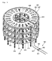
- Fig. 3 is a perspective view schematically illustrating a HVDC according to one embodiment
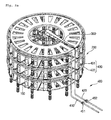
- Fig. 4 is a partially enlarged view of Fig. 3 .
- a configuration of a valve module 100 installed at a HVDC valve tower will be schematically described with reference to Fig. 4 , and then a configuration of the HVDC valve tower will be described with reference to Figs. 3 and 4 .
- Fig. 4 is an enlarged view illustrating a state in which one valve module 100 and a moving part 222 to be described later are withdrawn.
- the valve module 100 is to convert the direct current into the alternating current.
- a thyristor valve is used for the valve module 100
- an IGBT device is used for the valve module 100. Therefore, the valve module 100 constituting the HVDC valve tower according to one embodiment may be the thyristor valve or the IGBT device.
- the valve module 100 includes a case having an approximately rectangular parallelepiped outer shape, and various electronic components installed therein.
- the case of the valve module 100 has two cooling water ports 110.
- One of the two cooling water ports is an inlet port 111 through which the cooling water is introduced, and the other is an outlet port 112 through which the cooling water circulated in the valve module 100 is discharged.
- the cooling water ports 110 may be provided in an upper surface of the case around an external end of the case.
- the cooling water ports 110 do not necessarily have to be provided in the upper surface of the case.
- the cooling water ports 110 may be provided in an outer side surface directed in a radial direction of a valve module loading part, or may be provided in both side surfaces disposed at left and right sides of the outer side surface.
- a crane fixing part 120 which is coupled with a crane 300 is provided on an upper portion of the valve module 100.
- the crane fixing part 120 may be coupled with a hook or ring part of the crane 300.
- a protruding part 130 is provided at a lower portion of the valve module 100 to protrude downwardly.
- the protruding part 130 serves to be inserted into a concave portion of the moving part 222, which is described later, such that the valve module 100 may be stably located on the moving part 222.
- the HVDC valve tower includes the ring-shaped valve module loading part 200 having a predetermined height and width, and the crane 300 disposed at a central portion of the valve module loading part 200, and the cooling water circulation pipe 400 cooling the valve module 100.
- the valve module loading part 200 has a plurality of layers stacked up and down.
- Each of the layers includes a bottom frame 210, and a sliding part 220 which is coupled to the bottom frame 210 to be slid in a radial direction.
- the bottom frame 210 has an approximately circular plate shape of which a central portion is cut away. Since the bottom frame 210 serves to support the plurality of the valve modules 100, it may be made of a high stiffness material which may stably support a large load.
- the sliding part 220 includes a guide part 221 fixed to an upper surface of the bottom frame 210, and the moving part 222 moved along the guide part 221 in the radial direction.
- the guide part 221 may be a pair of rails which are extended in parallel.
- the moving part 222 may be a pair of bar type members which are extended in a sliding direction.
- a first cut-away part 222a (referring to Figs. 4 and 6d) which passes through the moving part 22 up and down is provided at a central part of the moving part 222.
- the first cut-away part 222a serves to effectively radiate heat generated from the valve module 100.
- a width between the pair of bar type members defining the moving part 222 should be smaller than that of the valve module 100, such that the valve module 100 may be put on the moving part 222.
- the concave portion which is opened upwardly and dented concavely downwardly may be defined in the moving part 222.
- the concave portion is a portion in which the protruding part 130 protruding downwardly at the lower portion of the valve module 100 is inserted so that the valve module 100 may be stably located on the moving part 222. Therefore, the protruding part 130 is slidably received in the concave portion.
- the moving part 222 may be a plate-shaped member which is provided to be slid along the rail, instead of the pair of bar type members. At this time, the central portion of the moving part 222 may be cut away to be passed through up and down, and this cut-away portion may define the first cut-away part 222a. As described above, the first cut-away part 222a is to effectively radiate the heat generated from the valve module 100.
- the bottom frame 210 may have a second cut-away part 211 (referring to Fig. 3 ) which is defined by cutting away a part or the whole of a portion of the bottom frame 210 corresponding to the valve module 100. More specifically, in a state in which the moving part 222 on which the valve module 100 is put is moved to be located at a vertical upper portion of the bottom frame 210, the second cut-away part 211 may be located at a lower side of a portion that the valve module 100 is located.
- the first cut-away part 222a and the second cut-away part 211 are overlapped with each other. That is, the first and second cut-away parts 222a and 211 are positioned to be overlapped up and down with each other. Therefore, the heat transferred through a lower portion of the thyristor valve module 1100 may be radiated through the first and second cut-away parts 222a and 211.
- the crane 300 is installed at a central portion of the valve module loading part 200 having the above-mentioned configuration. As described above, since the valve module loading part 200 has the hollow cylindrical shape, the crane 300 may be installed at the hollow portion.
- the crane 300 is installed to rotatable, and a transverse length of an arm of the crane 300 is greater than a radius of the valve module loading part 200.
- the valve module 100 is withdrawn to the outside together with the moving part 222, and the withdrawn valve module 100 is lifted up by the crane 300. While towing the valve module 100, the crane 300 is rotated so that the valve module 100 is moved from the vertical upper side of the moving part, and then the crane 300 lifts down the valve module 100 on the ground so as to perform a repairing or replacing operation.
- the cooling water circulation pipe 400 may be installed along an outer circumferential surface of the valve module loading part 200.
- the cooling water circulation pipe 400 includes an inlet pipe 410 extended up and down, an outlet pipe 420 extended up and down to be parallel with the inlet pipe 410, and a circulation pipe 430 connected with one of the inlet pipe 410 and the outlet pipe 420 and extended circularly.
- the circulation pipe 430 is provided up and down in plural. One end of the uppermost circulation pipe 430 is connected to the inlet pipe 410, and other end is maintained in a clogged state. One end of another circulation pipe 430 disposed just under the uppermost circulation pipe 430 is connected to the outlet pipe 420, and other end is maintained in the clogged state.
- the circulation pipe 430 of which the one end is connected to the inlet pipe 410 is referred to as an inlet circulation pipe 431
- the other circulation piper 430 of which the one end is connected to the outlet pipe 420 is referred to as an outlet circulation pipe 432. That is, the circulation pipe 430 includes the inlet circulation pipe 431 and the outlet circulation pipe 432.
- a plurality of connection pipes 440 are branched from each of the inlet circulation pipe 431 and the outlet circulation pipe 432. Pipe of the plurality of connection pipes 440 branched from the inlet circulation pipe 431 are connected to the inlet ports 111 of the valve modules 100, and pipes of the plurality of connection pipes 440 branched from the outlet circulation pipe 432 are connected to the outlet ports 112 of the valve modules 100.
- the cooling water supplied through the inlet pipe 410 is supplied to the plurality of inlet circulation pipes 431, and then introduced into each valve module 100 through the plurality of connection pipes 440 and each inlet port 111, while passing through the inlet circulation pipe 431.
- the cooling water introduced into the valve module 100 is circulated in the valve module 100, performs heat exchange, is discharged through the outlet port 112 of the valve module 100 and then discharged to the outlet circulation pipe 432 through the connection pipe 440.
- the cooling water discharged to the outlet circulation pipe 432 is discharged to an outside through the outlet pipe 420.
- a valve 451 may be provided at the inlet pipe 410, and another valve 452 may be also provided at the outlet pipe 420.
- valve 451 installed at the inlet pipe 410 is closed, and the outlet pipe 420 is maintained in an opened state.
- connection pipe 430 connected to the valve module 100 is separated. That is, the connection pipes 430 of the circulation pipe are separated from the inlet port 111 and the outlet port 112.
- the crane 300 is rotated so that the arm of the crane 300 is located at a position extended in the same direction as a radial extension direction of the valve module 100 to be withdrawn.
- valve module 100 is withdrawn to the outside. If force is applied to valve module 100 toward the outside, the moving part 222 is guided by the guide part 221 and moved to the outside, and thus the valve module 100 is withdrawn to the outside. In this state, the crane fixing part 120 of the crane 300 is connected with the crane 300.
- the crane 300 lifts up slightly and then rotates a predetermined angle. This is to prevent lifting down of the valve module 100 from being adhered with the moving part, when moving the valve module 100 to the ground or a predetermined height.
- valve module 100 is moved to the ground or the predetermined height, and the repairing, the checking or the replacing is performed.
- valve module 100 is lifted up by the crane 300, the crane 300 is rotated at the predetermined angle, and then the valve module 100 is lifted down.
- the crane 300 is not rotated, but the moving part 222 may be pushed to an inside, and then the valve module 100 may be lifted down.
- valve module 100 is connected to the crane 300 and then the crane 300 lifts up the valve module 100.
- valve module 100 is lifted up to a higher position than its original position, and the crane 300 is rotated so that the valve module 100 is located at an vertical upper side of the moving part 222.
- the crane 300 lifts down the valve module 100 so that the valve module 100 is put on the moving part 222, and then the crane 300 is separated from the valve module 100.
- valve module 100 is pushed to the inside, i.e., in a central direction, and thus the moving part 222 is guided by the guide part 221 and moved to the inside.
- connection pipes 430 of the circulation pipe are connected to the inlet port 111 and the outlet pipe 112 of the valve module 100.
- valve 451 connected to the inlet pipe 410 is opened so that the cooling water is circulated.
- the present invention it is easy to withdraw and install the valve module from/at the HVDC valve tower. Therefore, it is easy to perform the checking, repairing and replacing.
- valve modules are stacked up and down, it is easy to separate and install the valve modules, and also it is possible to install the HVDC valve tower without any space restriction even under a poor topography condition.
Landscapes
- Engineering & Computer Science (AREA)
- Power Engineering (AREA)
- Microelectronics & Electronic Packaging (AREA)
- Inverter Devices (AREA)
- Rectifiers (AREA)
- Details Of Valves (AREA)
- Direct Current Feeding And Distribution (AREA)
Abstract
Description
- The present disclosure relates to a high voltage direct current (HVDC) valve tower.
- A HVDC transmission system is to convert high-voltage AC power produced from a power plant into DC power using an electric power converter, transmit the converted DC power, convert again the DC power into the AC power and then supply the converted AC power.
- The HVDC transmission system has some advantages in that it has a low power loss, an insulation work is easy due to its lower voltage compared to the AC power, and a power transmission tower may have a reduced size and height due to its low induced lesion. Further, it is possible to connect two AC systems having different voltages or frequencies and thus to improve stability of the AC systems, and also when an AC system breaks down, it is possible to prevent the breakdown from being spread to other adjacent systems. Therefore, the HVDC transmission system is used as a power system connecting means of new renewable energy, particularly used for power transmission in a large-scale offshore wind generation farm, or the like.
- An AC/DC converting device for converting an alternating current into a direct current is provided at a HVDC substation in which the AC power is converted into the DC power.
- The AC/DC converting device is also called as a valve module (hereinafter, referred to as the "valve module"). In a current source HVDC system, a thyristor valve is used for the AC/DC converting device, and in a voltage source HVDC system, an IGBT device is used for the AC/DC converting device.
- In the HVDC system, the plurality of valve modules are vertically stacked according to a power transfer capability and constitutes a valve tower.
- As illustrated in
FIG. 1 , the valve tower may be fixed to an inner ceiling of the substation in order to protect the valve modules from environmental risk factors such as earthquake. -
FIG. 1 is a schematic view illustrating a general valve tower. Referring toFIG. 1 , the plurality ofvalve modules 10 are stacked on and connected with each other through supportinginsulators 20 and thus constitutes the valve tower. - The
valve modules 10 may be disassembled from the valve tower in order to have a periodic inspection or repair a trouble. However, since the plurality ofvalve modules 10 are connected in series, a part or the whole of thevalve modules 10 should be disassembled from the valve tower in order to separate aspecific valve module 10. That is, when separating theuppermost valve module 10, it is necessary to disassemble thevalve modules 10, in turn, from the lowermost one. Therefore, the whole of thevalve modules 10 should be disassembled in order to separate thespecific valve module 10. -
FIG. 2 is a schematic view illustrating another general valve tower. Referring toFIG. 2 , the plurality ofvalve modules 10 are stacked on and connected with each other through supportinginsulators 20 and thus constitutes the valve tower. - In this case, in order to separate the
valve module 10 from the valve tower, a hoist which is moved along a rail installed on the ceiling should be moved to a predetermined position, and then thevalve module 10 is separated by an operation of the hoist. - However, since the plurality of valve towers are generally installed over a comparatively wide area, the rail for moving the hoist should be also installed over the whole ceiling, and thus the cost of equipment is increased. Further, since it is necessary to move the hoist at the predetermined position and then perform the operation of the hoist, it takes a long period of working time.
- Embodiments provide a HVDC valve tower in which valve modules used in a high voltage direct current (HVDC) system are stacked up and down to have a cylindrical shape.
- In one embodiment, a HVDC valve tower includes a cylindrical valve module loading part, a valve module loaded on the valve module loading part, and a crane disposed at a center of the valve module loading part to be rotatable.
- The valve module loading part may have a plurality layers disposed up and down.
- The valve module loading part may include a plurality of bottom frames disposed up and down, a sliding part coupled to the bottom frame to be slid in a radial direction, and a valve module disposed on the sliding part.
- The sliding part may include a guide part configured to be fixed to the bottom frame, and a moving part configured to be guided by the guide part to be moved in the radial direction, and the valve module may be located on the moving part.
- The moving part may include a first cut-away part passing through the moving part up and down.
- The bottom frame may have a second cut-away part passing through the bottom frame up and down.
- The first and second cut-away parts may be disposed to be overlapped with each other.
- A crane fixing part which is coupled with a crane may be provided on an upper portion of the valve module.
- A protruding part may be provided at a lower portion of the valve module, and the moving part may have a concave portion which is opened upwardly and dented concavely downwardly, and the protruding part may be received in the concave portion to be slid.
- The details of one or more embodiments are set forth in the accompanying drawings and the description below. Other features will be apparent from the description and drawings, and from the claims.
-
-
Fig. 1 is a schematic view illustrating a general HVDC valve tower. -
Fig. 2 is a schematic view illustrating another general HVDC valve tower. -
Fig. 3 is a perspective view schematically illustrating a HVDC according to one embodiment. -
Fig. 4 is a partially enlarged view ofFig. 3 . -
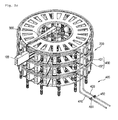
Figs. 5A to 5D are views illustrating an operating process of the HVDC valve tower according to one embodiment. - Reference will now be made in detail to the embodiments of the present disclosure, examples of which are illustrated in the accompanying drawings.
-
Fig. 3 is a perspective view schematically illustrating a HVDC according to one embodiment, andFig. 4 is a partially enlarged view ofFig. 3 . - Hereinafter, a configuration of a
valve module 100 installed at a HVDC valve tower will be schematically described with reference toFig. 4 , and then a configuration of the HVDC valve tower will be described with reference toFigs. 3 and4 . -
Fig. 4 is an enlarged view illustrating a state in which onevalve module 100 and a movingpart 222 to be described later are withdrawn. Thevalve module 100 is to convert the direct current into the alternating current. In a current source HVDC system, a thyristor valve is used for thevalve module 100, and in a voltage source HVDC system, an IGBT device is used for thevalve module 100. Therefore, thevalve module 100 constituting the HVDC valve tower according to one embodiment may be the thyristor valve or the IGBT device. - Referring to
Fig. 4 , thevalve module 100 includes a case having an approximately rectangular parallelepiped outer shape, and various electronic components installed therein. The case of thevalve module 100 has twocooling water ports 110. One of the two cooling water ports is aninlet port 111 through which the cooling water is introduced, and the other is anoutlet port 112 through which the cooling water circulated in thevalve module 100 is discharged. - At this time, the
cooling water ports 110 may be provided in an upper surface of the case around an external end of the case. However, thecooling water ports 110 do not necessarily have to be provided in the upper surface of the case. Thecooling water ports 110 may be provided in an outer side surface directed in a radial direction of a valve module loading part, or may be provided in both side surfaces disposed at left and right sides of the outer side surface. However, in any case, it is advantage in an aspect of maintenance that thecooling water ports 110 are provided around the external end of the case. For a periodic inspection, a repairing and the maintenance, thecorresponding valve module 100 should be withdrawn to an outside of the case. And before the withdrawing of thevalve module 100, a coolingwater circulation pipe 400 connected to thecooling water ports 110 should be separated from thecooling water ports 110. At this time, it is advantage that thecooling water ports 110 are located around the external end of the case. - Meanwhile, a
crane fixing part 120 which is coupled with acrane 300 is provided on an upper portion of thevalve module 100. Thecrane fixing part 120 may be coupled with a hook or ring part of thecrane 300. - A protruding
part 130 is provided at a lower portion of thevalve module 100 to protrude downwardly. Theprotruding part 130 serves to be inserted into a concave portion of the movingpart 222, which is described later, such that thevalve module 100 may be stably located on themoving part 222. - Referring to
Figs. 3 and4 , the HVDC valve tower includes the ring-shaped valvemodule loading part 200 having a predetermined height and width, and thecrane 300 disposed at a central portion of the valvemodule loading part 200, and the coolingwater circulation pipe 400 cooling thevalve module 100. - More specifically, the valve
module loading part 200 has a plurality of layers stacked up and down. Each of the layers includes abottom frame 210, and a slidingpart 220 which is coupled to thebottom frame 210 to be slid in a radial direction. - The
bottom frame 210 has an approximately circular plate shape of which a central portion is cut away. Since thebottom frame 210 serves to support the plurality of thevalve modules 100, it may be made of a high stiffness material which may stably support a large load. - An upper portion of the
bottom frame 210 is coupled with the slidingpart 220. The slidingpart 220 includes aguide part 221 fixed to an upper surface of thebottom frame 210, and the movingpart 222 moved along theguide part 221 in the radial direction. - Here, the
guide part 221 may be a pair of rails which are extended in parallel. Further, the movingpart 222 may be a pair of bar type members which are extended in a sliding direction. - A first cut-away part 222a (referring to
Figs. 4 and 6d) which passes through the moving part 22 up and down is provided at a central part of the movingpart 222. The first cut-away part 222a serves to effectively radiate heat generated from thevalve module 100. - At this time, a width between the pair of bar type members defining the moving
part 222 should be smaller than that of thevalve module 100, such that thevalve module 100 may be put on the movingpart 222. - Meanwhile, the concave portion which is opened upwardly and dented concavely downwardly may be defined in the moving
part 222. The concave portion is a portion in which theprotruding part 130 protruding downwardly at the lower portion of thevalve module 100 is inserted so that thevalve module 100 may be stably located on the movingpart 222. Therefore, the protrudingpart 130 is slidably received in the concave portion. - Meanwhile, the moving
part 222 may be a plate-shaped member which is provided to be slid along the rail, instead of the pair of bar type members. At this time, the central portion of the movingpart 222 may be cut away to be passed through up and down, and this cut-away portion may define the first cut-away part 222a. As described above, the first cut-away part 222a is to effectively radiate the heat generated from thevalve module 100. - Meanwhile, the
bottom frame 210 may have a second cut-away part 211 (referring toFig. 3 ) which is defined by cutting away a part or the whole of a portion of thebottom frame 210 corresponding to thevalve module 100. More specifically, in a state in which the movingpart 222 on which thevalve module 100 is put is moved to be located at a vertical upper portion of thebottom frame 210, the second cut-awaypart 211 may be located at a lower side of a portion that thevalve module 100 is located. - In a state in which the moving
part 222 is moved to an inner side of thebottom frame 210, the first cut-away part 222a and the second cut-awaypart 211 are overlapped with each other. That is, the first and second cut-awayparts 222a and 211 are positioned to be overlapped up and down with each other. Therefore, the heat transferred through a lower portion of the thyristor valve module 1100 may be radiated through the first and second cut-awayparts 222a and 211. - The
crane 300 is installed at a central portion of the valvemodule loading part 200 having the above-mentioned configuration. As described above, since the valvemodule loading part 200 has the hollow cylindrical shape, thecrane 300 may be installed at the hollow portion. - The
crane 300 is installed to rotatable, and a transverse length of an arm of thecrane 300 is greater than a radius of the valvemodule loading part 200. - In the above-mentioned structure, if the moving
part 222 is slid to an outside of thebottom frame 210, thevalve module 100 is withdrawn to the outside together with the movingpart 222, and the withdrawnvalve module 100 is lifted up by thecrane 300. While towing thevalve module 100, thecrane 300 is rotated so that thevalve module 100 is moved from the vertical upper side of the moving part, and then thecrane 300 lifts down thevalve module 100 on the ground so as to perform a repairing or replacing operation. - Meanwhile, the cooling
water circulation pipe 400 may be installed along an outer circumferential surface of the valvemodule loading part 200. The coolingwater circulation pipe 400 includes aninlet pipe 410 extended up and down, anoutlet pipe 420 extended up and down to be parallel with theinlet pipe 410, and acirculation pipe 430 connected with one of theinlet pipe 410 and theoutlet pipe 420 and extended circularly. - The
circulation pipe 430 is provided up and down in plural. One end of theuppermost circulation pipe 430 is connected to theinlet pipe 410, and other end is maintained in a clogged state. One end of anothercirculation pipe 430 disposed just under theuppermost circulation pipe 430 is connected to theoutlet pipe 420, and other end is maintained in the clogged state. - Hereinafter, the
circulation pipe 430 of which the one end is connected to theinlet pipe 410 is referred to as aninlet circulation pipe 431, and theother circulation piper 430 of which the one end is connected to theoutlet pipe 420 is referred to as anoutlet circulation pipe 432. That is, thecirculation pipe 430 includes theinlet circulation pipe 431 and theoutlet circulation pipe 432. - A plurality of
connection pipes 440 are branched from each of theinlet circulation pipe 431 and theoutlet circulation pipe 432. Pipe of the plurality ofconnection pipes 440 branched from theinlet circulation pipe 431 are connected to theinlet ports 111 of thevalve modules 100, and pipes of the plurality ofconnection pipes 440 branched from theoutlet circulation pipe 432 are connected to theoutlet ports 112 of thevalve modules 100. - Therefore, the cooling water supplied through the
inlet pipe 410 is supplied to the plurality ofinlet circulation pipes 431, and then introduced into eachvalve module 100 through the plurality ofconnection pipes 440 and eachinlet port 111, while passing through theinlet circulation pipe 431. - The cooling water introduced into the
valve module 100 is circulated in thevalve module 100, performs heat exchange, is discharged through theoutlet port 112 of thevalve module 100 and then discharged to theoutlet circulation pipe 432 through theconnection pipe 440. The cooling water discharged to theoutlet circulation pipe 432 is discharged to an outside through theoutlet pipe 420. - At this time, a
valve 451 may be provided at theinlet pipe 410, and anothervalve 452 may be also provided at theoutlet pipe 420. - Hereinafter, a process of separating the
valve module 100 from the HVDC tower will be described with reference toFigs. 5A to 5D . - As shown in
Fig. 5A , at an initial state, if thevalve module 100 to be checked, repaired or replaced is decided, thevalve 451 installed at theinlet pipe 410 is closed, and theoutlet pipe 420 is maintained in an opened state. - The cooling water is completely discharged in this state, and then the
connection pipe 430 connected to thevalve module 100 is separated. That is, theconnection pipes 430 of the circulation pipe are separated from theinlet port 111 and theoutlet port 112. - Then, as shown in
Fig. 5b , thecrane 300 is rotated so that the arm of thecrane 300 is located at a position extended in the same direction as a radial extension direction of thevalve module 100 to be withdrawn. - In this state, as shown in
Fig. 5c , thevalve module 100 is withdrawn to the outside. If force is applied tovalve module 100 toward the outside, the movingpart 222 is guided by theguide part 221 and moved to the outside, and thus thevalve module 100 is withdrawn to the outside. In this state, thecrane fixing part 120 of thecrane 300 is connected with thecrane 300. - If the
valve module 100 is connected to thecrane 300, thecrane 300 lifts up slightly and then rotates a predetermined angle. This is to prevent lifting down of thevalve module 100 from being adhered with the moving part, when moving thevalve module 100 to the ground or a predetermined height. - Then, as shown in
Fig. 5D , thevalve module 100 is moved to the ground or the predetermined height, and the repairing, the checking or the replacing is performed. - Meanwhile, in the above description, the
valve module 100 is lifted up by thecrane 300, thecrane 300 is rotated at the predetermined angle, and then thevalve module 100 is lifted down. On the other hand, after thevalve module 100 is lifted up by thecrane 300, thecrane 300 is not rotated, but the movingpart 222 may be pushed to an inside, and then thevalve module 100 may be lifted down. - And in order to couple again the
finished valve module 100 or a new valve module to be replaced to the valvemodule loading part 200, the above-mentioned process is reversely performed. - First of all, the
valve module 100 is connected to thecrane 300 and then thecrane 300 lifts up thevalve module 100. - The
valve module 100 is lifted up to a higher position than its original position, and thecrane 300 is rotated so that thevalve module 100 is located at an vertical upper side of the movingpart 222. - In this state, the
crane 300 lifts down thevalve module 100 so that thevalve module 100 is put on the movingpart 222, and then thecrane 300 is separated from thevalve module 100. - And the
valve module 100 is pushed to the inside, i.e., in a central direction, and thus the movingpart 222 is guided by theguide part 221 and moved to the inside. - When the
valve module 100 is located at its own position, theconnection pipes 430 of the circulation pipe are connected to theinlet port 111 and theoutlet pipe 112 of thevalve module 100. - Then, the
valve 451 connected to theinlet pipe 410 is opened so that the cooling water is circulated. - According to the present invention, it is easy to withdraw and install the valve module from/at the HVDC valve tower. Therefore, it is easy to perform the checking, repairing and replacing.
- Further, it is possible to reduce the cost of equipment for the substation. And even though the valve modules are stacked up and down, it is easy to separate and install the valve modules, and also it is possible to install the HVDC valve tower without any space restriction even under a poor topography condition.
- Although embodiments have been described with reference to a number of illustrative embodiments thereof, it should be understood that numerous other modifications and embodiments can be devised by those skilled in the art that will fall within the spirit and scope of the principles of this disclosure. More particularly, various variations and modifications are possible in the component parts and/or arrangements of the subject combination arrangement within the scope of the disclosure, the drawings and the appended claims. In addition to variations and modifications in the component parts and/or arrangements, alternative uses will also be apparent to those skilled in the art.
Claims (9)
- A HVDC valve tower comprising:a cylindrical valve module loading part;a valve module loaded on the valve module loading part; anda crane disposed at a center of the valve module loading part to be rotatable.
- The HVDC valve tower according to claim 1, wherein the valve module loading part has a plurality layers disposed up and down.
- The HVDC valve tower according to claim 2, wherein the valve module loading part comprises,
a plurality of bottom frames disposed up and down,
a sliding part coupled to the bottom frame to be slid in a radial direction, and
a valve module disposed on the sliding part. - The HVDC valve tower according to claim 3, wherein the sliding part comprises,
a guide part configured to be fixed to the bottom frame, and a moving part configured to be guided by the guide part to be moved in the radial direction, and
the valve module is located on the moving part. - The HVDC valve tower according to claim 4, wherein the moving part comprises a first cut-away part passing through the moving part up and down.
- The HVDC valve tower according to claim 5, wherein the bottom frame has a second cut-away part passing through the bottom frame up and down.
- The HVDC valve tower according to claim 6, wherein the first and second cut-away parts are disposed to be overlapped with each other.
- The HVDC valve tower according to claim 1, wherein a crane fixing part which is coupled with a crane is provided on an upper portion of the valve module.
- The HVDC valve tower according to claim 4, wherein a protruding part is provided at a lower portion of the valve module, and the moving part has a concave portion which is opened upwardly and dented concavely downwardly, and the protruding part is received in the concave portion to be slid.
Applications Claiming Priority (1)
| Application Number | Priority Date | Filing Date | Title |
|---|---|---|---|
| KR1020130048597A KR101758417B1 (en) | 2013-04-30 | 2013-04-30 | Hvdc valve tower |
Publications (2)
| Publication Number | Publication Date |
|---|---|
| EP2800133A1 true EP2800133A1 (en) | 2014-11-05 |
| EP2800133B1 EP2800133B1 (en) | 2016-05-11 |
Family
ID=50440481
Family Applications (1)
| Application Number | Title | Priority Date | Filing Date |
|---|---|---|---|
| EP14162262.1A Active EP2800133B1 (en) | 2013-04-30 | 2014-03-28 | Hvdc valve tower |
Country Status (6)
| Country | Link |
|---|---|
| US (1) | US9331485B2 (en) |
| EP (1) | EP2800133B1 (en) |
| JP (1) | JP5952335B2 (en) |
| KR (1) | KR101758417B1 (en) |
| CN (1) | CN104135167B (en) |
| ES (1) | ES2586715T3 (en) |
Cited By (2)
| Publication number | Priority date | Publication date | Assignee | Title |
|---|---|---|---|---|
| WO2018077680A1 (en) | 2016-10-31 | 2018-05-03 | Siemens Aktiengesellschaft | Electrical device and method for the maintenance thereof |
| EP3282573A4 (en) * | 2015-04-06 | 2018-11-21 | Mitsubishi Electric Corporation | Power conversion device |
Families Citing this family (7)
| Publication number | Priority date | Publication date | Assignee | Title |
|---|---|---|---|---|
| JP2016088950A (en) | 2014-10-30 | 2016-05-23 | 信越化学工業株式会社 | Red phosphor |
| US10122292B2 (en) * | 2015-05-28 | 2018-11-06 | Nr Electric Co., Ltd | Converter valve |
| KR102145029B1 (en) | 2017-04-28 | 2020-08-14 | 엘에스일렉트릭(주) | Apparatus of sliding a submodule |
| KR102017264B1 (en) | 2017-09-12 | 2019-09-02 | 장재성 | Wheel foldable wheelchair |
| CN111969634A (en) | 2019-05-20 | 2020-11-20 | 南京南瑞继保工程技术有限公司 | Valve tower reinforced structure |
| KR102304939B1 (en) | 2019-08-01 | 2021-09-24 | 장재성 | Wheelchair of variables type |
| CN113131759A (en) * | 2020-01-15 | 2021-07-16 | 许继集团有限公司 | Converter valve tower |
Citations (2)
| Publication number | Priority date | Publication date | Assignee | Title |
|---|---|---|---|---|
| JPH06343267A (en) * | 1993-05-31 | 1994-12-13 | Toshiba Corp | Thyristor valve |
| JPH07176687A (en) * | 1993-12-20 | 1995-07-14 | Toshiba Corp | Thyristor valve |
Family Cites Families (12)
| Publication number | Priority date | Publication date | Assignee | Title |
|---|---|---|---|---|
| CA807271A (en) * | 1965-10-20 | 1969-02-25 | Paul Evans, Jr. | Semiconductor converter with cooling and shielding means |
| US4002243A (en) * | 1974-12-11 | 1977-01-11 | Stanspec Co. | Jib crane |
| JPS5785581A (en) * | 1980-11-14 | 1982-05-28 | Hitachi Ltd | Maintenance device for thyristor valve |
| JPS61188304A (en) | 1985-02-14 | 1986-08-22 | Kumahira Safe Co Inc | Safe-deposit facility |
| US5106255A (en) * | 1990-10-04 | 1992-04-21 | Motoda Electronics Co., Ltd. | Posture adjusting mechanism of cargo handling device for use in cargo trucks |
| US5083395A (en) * | 1991-05-02 | 1992-01-28 | Daniels Angela F | Crab cage and pole apparatus |
| JPH06311728A (en) * | 1993-04-21 | 1994-11-04 | Mitsubishi Electric Corp | Thyristor valve |
| JP4034709B2 (en) * | 2003-08-08 | 2008-01-16 | 東芝三菱電機産業システム株式会社 | Power converter |
| JP4535251B2 (en) | 2004-08-23 | 2010-09-01 | Hoya株式会社 | Manufacturing method of lubricant for magnetic disk |
| JP4643611B2 (en) | 2007-05-21 | 2011-03-02 | 東芝三菱電機産業システム株式会社 | Power converter |
| JP5578213B2 (en) * | 2012-08-30 | 2014-08-27 | 株式会社安川電機 | Carry-in / out device |
| US9166383B2 (en) * | 2014-02-25 | 2015-10-20 | Eaton Corporation | Load center and switchgear mounting assembly therefor |
-
2013
- 2013-04-30 KR KR1020130048597A patent/KR101758417B1/en active Active
-
2014
- 2014-03-28 ES ES14162262.1T patent/ES2586715T3/en active Active
- 2014-03-28 EP EP14162262.1A patent/EP2800133B1/en active Active
- 2014-04-17 US US14/255,655 patent/US9331485B2/en active Active
- 2014-04-28 JP JP2014092315A patent/JP5952335B2/en active Active
- 2014-04-29 CN CN201410177946.5A patent/CN104135167B/en active Active
Patent Citations (2)
| Publication number | Priority date | Publication date | Assignee | Title |
|---|---|---|---|---|
| JPH06343267A (en) * | 1993-05-31 | 1994-12-13 | Toshiba Corp | Thyristor valve |
| JPH07176687A (en) * | 1993-12-20 | 1995-07-14 | Toshiba Corp | Thyristor valve |
Non-Patent Citations (1)
| Title |
|---|
| "Capacitors and Filters Improving power quality for efficiency and reliability", 1 November 2010 (2010-11-01), XP055135143, Retrieved from the Internet <URL:https://web.archive.org/web/20120526071744/http://www05.abb.com/global/scot/scot245.nsf/veritydisplay/29b24f474aa7e4e4c12577e50057910c/$file/ABB_1HSM954331-01_Capacitors_and_Filters_EN.pdf> [retrieved on 20140818] * |
Cited By (4)
| Publication number | Priority date | Publication date | Assignee | Title |
|---|---|---|---|---|
| EP3282573A4 (en) * | 2015-04-06 | 2018-11-21 | Mitsubishi Electric Corporation | Power conversion device |
| US10389268B2 (en) | 2015-04-06 | 2019-08-20 | Mitsubishi Electric Corporation | AC-DC power conversion device including helically cascaded unit cells |
| WO2018077680A1 (en) | 2016-10-31 | 2018-05-03 | Siemens Aktiengesellschaft | Electrical device and method for the maintenance thereof |
| DE102016221405A1 (en) | 2016-10-31 | 2018-05-03 | Siemens Aktiengesellschaft | Electrical device and method for its maintenance |
Also Published As
| Publication number | Publication date |
|---|---|
| KR101758417B1 (en) | 2017-07-17 |
| JP2014220993A (en) | 2014-11-20 |
| CN104135167B (en) | 2017-05-31 |
| EP2800133B1 (en) | 2016-05-11 |
| KR20140130316A (en) | 2014-11-10 |
| US20140321095A1 (en) | 2014-10-30 |
| US9331485B2 (en) | 2016-05-03 |
| JP5952335B2 (en) | 2016-07-13 |
| CN104135167A (en) | 2014-11-05 |
| ES2586715T3 (en) | 2016-10-18 |
Similar Documents
| Publication | Publication Date | Title |
|---|---|---|
| US9331485B2 (en) | HVDC valve tower | |
| TWI662186B (en) | Construction method of offshore windmill, offshore windmill and offshore wind power generation equipment | |
| KR101835916B1 (en) | Nuclear steam generator support and alignment structure | |
| US10629313B2 (en) | Control rod drive mechanism (CRDM) mounting method for pressurized water reactors | |
| US10119523B2 (en) | Method for moving wind turbine components and a transport system for moving wind turbine components | |
| CN104652864B (en) | Offshore platform for offshore wind power flexible direct current connecting-in system | |
| CN103956763B (en) | Flexible direct current converter station | |
| KR20130075778A (en) | Method for replacing a transformer in a wind energy installation | |
| US12320330B2 (en) | Method for producing a wind turbine, a method for demounting a module, a nacelle structure and a wind turbine | |
| CN104612908A (en) | Wind power generation tower cylinder platform and wind power generation tower cylinder | |
| US20160300655A1 (en) | Site Replacement Of Internal Saturable Reactors Of A Rectifier Power Transformer | |
| WO2019207188A1 (en) | Movable module for hoisting telescopic towers and method for hoisting telescopic towers | |
| CN106762473A (en) | Wind power generating set | |
| KR20140130317A (en) | Cooling water circulation systme for hvdc valve tower | |
| CN203826980U (en) | Flexible DC converter station | |
| CN203866800U (en) | Offshore booster station | |
| CN203338917U (en) | Transformer with split windings | |
| CN106481512B (en) | Wind power plant and method for replacing equipment in its nacelle | |
| CN215956771U (en) | Safe type high-efficient heat transfer energy storage cabinet | |
| KR20250010604A (en) | Solid oxide electrolysis unit | |
| CN204167684U (en) | A kind of current transformer | |
| CN201901560U (en) | Device for installing rope blocking tube | |
| CN111023235A (en) | Movable solid electric heat storage and release integrated device with container | |
| CN112531514A (en) | Low-voltage power distribution energy-saving device and control method thereof | |
| CN211308371U (en) | Movable vehicle-mounted transformer |
Legal Events
| Date | Code | Title | Description |
|---|---|---|---|
| PUAI | Public reference made under article 153(3) epc to a published international application that has entered the european phase |
Free format text: ORIGINAL CODE: 0009012 |
|
| 17P | Request for examination filed |
Effective date: 20140328 |
|
| AK | Designated contracting states |
Kind code of ref document: A1 Designated state(s): AL AT BE BG CH CY CZ DE DK EE ES FI FR GB GR HR HU IE IS IT LI LT LU LV MC MK MT NL NO PL PT RO RS SE SI SK SM TR |
|
| AX | Request for extension of the european patent |
Extension state: BA ME |
|
| R17P | Request for examination filed (corrected) |
Effective date: 20150430 |
|
| RBV | Designated contracting states (corrected) |
Designated state(s): AL AT BE BG CH CY CZ DE DK EE ES FI FR GB GR HR HU IE IS IT LI LT LU LV MC MK MT NL NO PL PT RO RS SE SI SK SM TR |
|
| GRAP | Despatch of communication of intention to grant a patent |
Free format text: ORIGINAL CODE: EPIDOSNIGR1 |
|
| RIC1 | Information provided on ipc code assigned before grant |
Ipc: H02B 1/00 20060101ALI20151021BHEP Ipc: H01L 25/11 20060101AFI20151021BHEP |
|
| INTG | Intention to grant announced |
Effective date: 20151106 |
|
| GRAS | Grant fee paid |
Free format text: ORIGINAL CODE: EPIDOSNIGR3 |
|
| GRAA | (expected) grant |
Free format text: ORIGINAL CODE: 0009210 |
|
| AK | Designated contracting states |
Kind code of ref document: B1 Designated state(s): AL AT BE BG CH CY CZ DE DK EE ES FI FR GB GR HR HU IE IS IT LI LT LU LV MC MK MT NL NO PL PT RO RS SE SI SK SM TR |
|
| REG | Reference to a national code |
Ref country code: GB Ref legal event code: FG4D |
|
| REG | Reference to a national code |
Ref country code: CH Ref legal event code: EP |
|
| REG | Reference to a national code |
Ref country code: AT Ref legal event code: REF Ref document number: 799267 Country of ref document: AT Kind code of ref document: T Effective date: 20160515 |
|
| REG | Reference to a national code |
Ref country code: IE Ref legal event code: FG4D |
|
| REG | Reference to a national code |
Ref country code: DE Ref legal event code: R096 Ref document number: 602014001843 Country of ref document: DE |
|
| REG | Reference to a national code |
Ref country code: LT Ref legal event code: MG4D |
|
| REG | Reference to a national code |
Ref country code: NL Ref legal event code: MP Effective date: 20160511 |
|
| REG | Reference to a national code |
Ref country code: ES Ref legal event code: FG2A Ref document number: 2586715 Country of ref document: ES Kind code of ref document: T3 Effective date: 20161018 |
|
| PG25 | Lapsed in a contracting state [announced via postgrant information from national office to epo] |
Ref country code: NO Free format text: LAPSE BECAUSE OF FAILURE TO SUBMIT A TRANSLATION OF THE DESCRIPTION OR TO PAY THE FEE WITHIN THE PRESCRIBED TIME-LIMIT Effective date: 20160811 Ref country code: FI Free format text: LAPSE BECAUSE OF FAILURE TO SUBMIT A TRANSLATION OF THE DESCRIPTION OR TO PAY THE FEE WITHIN THE PRESCRIBED TIME-LIMIT Effective date: 20160511 Ref country code: LT Free format text: LAPSE BECAUSE OF FAILURE TO SUBMIT A TRANSLATION OF THE DESCRIPTION OR TO PAY THE FEE WITHIN THE PRESCRIBED TIME-LIMIT Effective date: 20160511 Ref country code: NL Free format text: LAPSE BECAUSE OF FAILURE TO SUBMIT A TRANSLATION OF THE DESCRIPTION OR TO PAY THE FEE WITHIN THE PRESCRIBED TIME-LIMIT Effective date: 20160511 |
|
| REG | Reference to a national code |
Ref country code: AT Ref legal event code: MK05 Ref document number: 799267 Country of ref document: AT Kind code of ref document: T Effective date: 20160511 |
|
| PG25 | Lapsed in a contracting state [announced via postgrant information from national office to epo] |
Ref country code: PT Free format text: LAPSE BECAUSE OF FAILURE TO SUBMIT A TRANSLATION OF THE DESCRIPTION OR TO PAY THE FEE WITHIN THE PRESCRIBED TIME-LIMIT Effective date: 20160912 Ref country code: LV Free format text: LAPSE BECAUSE OF FAILURE TO SUBMIT A TRANSLATION OF THE DESCRIPTION OR TO PAY THE FEE WITHIN THE PRESCRIBED TIME-LIMIT Effective date: 20160511 Ref country code: SE Free format text: LAPSE BECAUSE OF FAILURE TO SUBMIT A TRANSLATION OF THE DESCRIPTION OR TO PAY THE FEE WITHIN THE PRESCRIBED TIME-LIMIT Effective date: 20160511 Ref country code: RS Free format text: LAPSE BECAUSE OF FAILURE TO SUBMIT A TRANSLATION OF THE DESCRIPTION OR TO PAY THE FEE WITHIN THE PRESCRIBED TIME-LIMIT Effective date: 20160511 Ref country code: GR Free format text: LAPSE BECAUSE OF FAILURE TO SUBMIT A TRANSLATION OF THE DESCRIPTION OR TO PAY THE FEE WITHIN THE PRESCRIBED TIME-LIMIT Effective date: 20160812 Ref country code: HR Free format text: LAPSE BECAUSE OF FAILURE TO SUBMIT A TRANSLATION OF THE DESCRIPTION OR TO PAY THE FEE WITHIN THE PRESCRIBED TIME-LIMIT Effective date: 20160511 |
|
| REG | Reference to a national code |
Ref country code: FR Ref legal event code: PLFP Year of fee payment: 4 |
|
| PG25 | Lapsed in a contracting state [announced via postgrant information from national office to epo] |
Ref country code: CZ Free format text: LAPSE BECAUSE OF FAILURE TO SUBMIT A TRANSLATION OF THE DESCRIPTION OR TO PAY THE FEE WITHIN THE PRESCRIBED TIME-LIMIT Effective date: 20160511 Ref country code: DK Free format text: LAPSE BECAUSE OF FAILURE TO SUBMIT A TRANSLATION OF THE DESCRIPTION OR TO PAY THE FEE WITHIN THE PRESCRIBED TIME-LIMIT Effective date: 20160511 Ref country code: SK Free format text: LAPSE BECAUSE OF FAILURE TO SUBMIT A TRANSLATION OF THE DESCRIPTION OR TO PAY THE FEE WITHIN THE PRESCRIBED TIME-LIMIT Effective date: 20160511 Ref country code: EE Free format text: LAPSE BECAUSE OF FAILURE TO SUBMIT A TRANSLATION OF THE DESCRIPTION OR TO PAY THE FEE WITHIN THE PRESCRIBED TIME-LIMIT Effective date: 20160511 Ref country code: RO Free format text: LAPSE BECAUSE OF FAILURE TO SUBMIT A TRANSLATION OF THE DESCRIPTION OR TO PAY THE FEE WITHIN THE PRESCRIBED TIME-LIMIT Effective date: 20160511 |
|
| REG | Reference to a national code |
Ref country code: DE Ref legal event code: R097 Ref document number: 602014001843 Country of ref document: DE |
|
| PG25 | Lapsed in a contracting state [announced via postgrant information from national office to epo] |
Ref country code: BE Free format text: LAPSE BECAUSE OF FAILURE TO SUBMIT A TRANSLATION OF THE DESCRIPTION OR TO PAY THE FEE WITHIN THE PRESCRIBED TIME-LIMIT Effective date: 20160511 Ref country code: AT Free format text: LAPSE BECAUSE OF FAILURE TO SUBMIT A TRANSLATION OF THE DESCRIPTION OR TO PAY THE FEE WITHIN THE PRESCRIBED TIME-LIMIT Effective date: 20160511 Ref country code: SM Free format text: LAPSE BECAUSE OF FAILURE TO SUBMIT A TRANSLATION OF THE DESCRIPTION OR TO PAY THE FEE WITHIN THE PRESCRIBED TIME-LIMIT Effective date: 20160511 Ref country code: PL Free format text: LAPSE BECAUSE OF FAILURE TO SUBMIT A TRANSLATION OF THE DESCRIPTION OR TO PAY THE FEE WITHIN THE PRESCRIBED TIME-LIMIT Effective date: 20160511 |
|
| PLBE | No opposition filed within time limit |
Free format text: ORIGINAL CODE: 0009261 |
|
| STAA | Information on the status of an ep patent application or granted ep patent |
Free format text: STATUS: NO OPPOSITION FILED WITHIN TIME LIMIT |
|
| 26N | No opposition filed |
Effective date: 20170214 |
|
| PG25 | Lapsed in a contracting state [announced via postgrant information from national office to epo] |
Ref country code: SI Free format text: LAPSE BECAUSE OF FAILURE TO SUBMIT A TRANSLATION OF THE DESCRIPTION OR TO PAY THE FEE WITHIN THE PRESCRIBED TIME-LIMIT Effective date: 20160511 |
|
| REG | Reference to a national code |
Ref country code: CH Ref legal event code: PL |
|
| PG25 | Lapsed in a contracting state [announced via postgrant information from national office to epo] |
Ref country code: MC Free format text: LAPSE BECAUSE OF FAILURE TO SUBMIT A TRANSLATION OF THE DESCRIPTION OR TO PAY THE FEE WITHIN THE PRESCRIBED TIME-LIMIT Effective date: 20160511 |
|
| REG | Reference to a national code |
Ref country code: IE Ref legal event code: MM4A |
|
| REG | Reference to a national code |
Ref country code: FR Ref legal event code: PLFP Year of fee payment: 5 |
|
| PG25 | Lapsed in a contracting state [announced via postgrant information from national office to epo] |
Ref country code: LU Free format text: LAPSE BECAUSE OF NON-PAYMENT OF DUE FEES Effective date: 20170328 |
|
| PG25 | Lapsed in a contracting state [announced via postgrant information from national office to epo] |
Ref country code: LI Free format text: LAPSE BECAUSE OF NON-PAYMENT OF DUE FEES Effective date: 20170331 Ref country code: IE Free format text: LAPSE BECAUSE OF NON-PAYMENT OF DUE FEES Effective date: 20170328 Ref country code: CH Free format text: LAPSE BECAUSE OF NON-PAYMENT OF DUE FEES Effective date: 20170331 |
|
| PG25 | Lapsed in a contracting state [announced via postgrant information from national office to epo] |
Ref country code: MT Free format text: LAPSE BECAUSE OF NON-PAYMENT OF DUE FEES Effective date: 20170328 |
|
| PG25 | Lapsed in a contracting state [announced via postgrant information from national office to epo] |
Ref country code: AL Free format text: LAPSE BECAUSE OF FAILURE TO SUBMIT A TRANSLATION OF THE DESCRIPTION OR TO PAY THE FEE WITHIN THE PRESCRIBED TIME-LIMIT Effective date: 20160511 |
|
| PG25 | Lapsed in a contracting state [announced via postgrant information from national office to epo] |
Ref country code: HU Free format text: LAPSE BECAUSE OF FAILURE TO SUBMIT A TRANSLATION OF THE DESCRIPTION OR TO PAY THE FEE WITHIN THE PRESCRIBED TIME-LIMIT; INVALID AB INITIO Effective date: 20140328 |
|
| PG25 | Lapsed in a contracting state [announced via postgrant information from national office to epo] |
Ref country code: BG Free format text: LAPSE BECAUSE OF FAILURE TO SUBMIT A TRANSLATION OF THE DESCRIPTION OR TO PAY THE FEE WITHIN THE PRESCRIBED TIME-LIMIT Effective date: 20160511 |
|
| PG25 | Lapsed in a contracting state [announced via postgrant information from national office to epo] |
Ref country code: CY Free format text: LAPSE BECAUSE OF FAILURE TO SUBMIT A TRANSLATION OF THE DESCRIPTION OR TO PAY THE FEE WITHIN THE PRESCRIBED TIME-LIMIT Effective date: 20160511 |
|
| PG25 | Lapsed in a contracting state [announced via postgrant information from national office to epo] |
Ref country code: MK Free format text: LAPSE BECAUSE OF FAILURE TO SUBMIT A TRANSLATION OF THE DESCRIPTION OR TO PAY THE FEE WITHIN THE PRESCRIBED TIME-LIMIT Effective date: 20160511 |
|
| PG25 | Lapsed in a contracting state [announced via postgrant information from national office to epo] |
Ref country code: TR Free format text: LAPSE BECAUSE OF FAILURE TO SUBMIT A TRANSLATION OF THE DESCRIPTION OR TO PAY THE FEE WITHIN THE PRESCRIBED TIME-LIMIT Effective date: 20160511 |
|
| PG25 | Lapsed in a contracting state [announced via postgrant information from national office to epo] |
Ref country code: IS Free format text: LAPSE BECAUSE OF FAILURE TO SUBMIT A TRANSLATION OF THE DESCRIPTION OR TO PAY THE FEE WITHIN THE PRESCRIBED TIME-LIMIT Effective date: 20160911 |
|
| P01 | Opt-out of the competence of the unified patent court (upc) registered |
Effective date: 20230625 |
|
| PGFP | Annual fee paid to national office [announced via postgrant information from national office to epo] |
Ref country code: ES Payment date: 20250408 Year of fee payment: 12 |
|
| REG | Reference to a national code |
Ref country code: DE Ref legal event code: R079 Ref document number: 602014001843 Country of ref document: DE Free format text: PREVIOUS MAIN CLASS: H01L0025110000 Ipc: H10D0080200000 |
|
| PGFP | Annual fee paid to national office [announced via postgrant information from national office to epo] |
Ref country code: FR Payment date: 20251209 Year of fee payment: 13 |
|
| PGFP | Annual fee paid to national office [announced via postgrant information from national office to epo] |
Ref country code: GB Payment date: 20260108 Year of fee payment: 13 |
|
| PGFP | Annual fee paid to national office [announced via postgrant information from national office to epo] |
Ref country code: DE Payment date: 20251208 Year of fee payment: 13 |
|
| PGFP | Annual fee paid to national office [announced via postgrant information from national office to epo] |
Ref country code: IT Payment date: 20251209 Year of fee payment: 13 |