EP2800090A2 - Schallerzeuger für eine Abgasanlage - Google Patents
Schallerzeuger für eine Abgasanlage Download PDFInfo
- Publication number
- EP2800090A2 EP2800090A2 EP14165579.5A EP14165579A EP2800090A2 EP 2800090 A2 EP2800090 A2 EP 2800090A2 EP 14165579 A EP14165579 A EP 14165579A EP 2800090 A2 EP2800090 A2 EP 2800090A2
- Authority
- EP
- European Patent Office
- Prior art keywords
- housing
- pressure equalization
- sound generator
- distal end
- vehicle
- Prior art date
- Legal status (The legal status is an assumption and is not a legal conclusion. Google has not performed a legal analysis and makes no representation as to the accuracy of the status listed.)
- Granted
Links
Images
Classifications
-
- G—PHYSICS
- G10—MUSICAL INSTRUMENTS; ACOUSTICS
- G10K—SOUND-PRODUCING DEVICES; METHODS OR DEVICES FOR PROTECTING AGAINST, OR FOR DAMPING, NOISE OR OTHER ACOUSTIC WAVES IN GENERAL; ACOUSTICS NOT OTHERWISE PROVIDED FOR
- G10K11/00—Methods or devices for transmitting, conducting or directing sound in general; Methods or devices for protecting against, or for damping, noise or other acoustic waves in general
- G10K11/16—Methods or devices for protecting against, or for damping, noise or other acoustic waves in general
- G10K11/175—Methods or devices for protecting against, or for damping, noise or other acoustic waves in general using interference effects; Masking sound
- G10K11/178—Methods or devices for protecting against, or for damping, noise or other acoustic waves in general using interference effects; Masking sound by electro-acoustically regenerating the original acoustic waves in anti-phase
-
- F—MECHANICAL ENGINEERING; LIGHTING; HEATING; WEAPONS; BLASTING
- F01—MACHINES OR ENGINES IN GENERAL; ENGINE PLANTS IN GENERAL; STEAM ENGINES
- F01N—GAS-FLOW SILENCERS OR EXHAUST APPARATUS FOR MACHINES OR ENGINES IN GENERAL; GAS-FLOW SILENCERS OR EXHAUST APPARATUS FOR INTERNAL-COMBUSTION ENGINES
- F01N1/00—Silencing apparatus characterised by method of silencing
- F01N1/06—Silencing apparatus characterised by method of silencing by using interference effect
- F01N1/065—Silencing apparatus characterised by method of silencing by using interference effect by using an active noise source, e.g. speakers
-
- F—MECHANICAL ENGINEERING; LIGHTING; HEATING; WEAPONS; BLASTING
- F01—MACHINES OR ENGINES IN GENERAL; ENGINE PLANTS IN GENERAL; STEAM ENGINES
- F01N—GAS-FLOW SILENCERS OR EXHAUST APPARATUS FOR MACHINES OR ENGINES IN GENERAL; GAS-FLOW SILENCERS OR EXHAUST APPARATUS FOR INTERNAL-COMBUSTION ENGINES
- F01N13/00—Exhaust or silencing apparatus characterised by constructional features
- F01N13/08—Other arrangements or adaptations of exhaust conduits
-
- H—ELECTRICITY
- H04—ELECTRIC COMMUNICATION TECHNIQUE
- H04R—LOUDSPEAKERS, MICROPHONES, GRAMOPHONE PICK-UPS OR LIKE ACOUSTIC ELECTROMECHANICAL TRANSDUCERS; ELECTRIC HEARING AIDS; PUBLIC ADDRESS SYSTEMS
- H04R1/00—Details of transducers, loudspeakers or microphones
- H04R1/02—Casings; Cabinets ; Supports therefor; Mountings therein
- H04R1/028—Casings; Cabinets ; Supports therefor; Mountings therein associated with devices performing functions other than acoustics, e.g. electric candles
-
- F—MECHANICAL ENGINEERING; LIGHTING; HEATING; WEAPONS; BLASTING
- F01—MACHINES OR ENGINES IN GENERAL; ENGINE PLANTS IN GENERAL; STEAM ENGINES
- F01N—GAS-FLOW SILENCERS OR EXHAUST APPARATUS FOR MACHINES OR ENGINES IN GENERAL; GAS-FLOW SILENCERS OR EXHAUST APPARATUS FOR INTERNAL-COMBUSTION ENGINES
- F01N13/00—Exhaust or silencing apparatus characterised by constructional features
- F01N13/18—Construction facilitating manufacture, assembly, or disassembly
-
- F—MECHANICAL ENGINEERING; LIGHTING; HEATING; WEAPONS; BLASTING
- F01—MACHINES OR ENGINES IN GENERAL; ENGINE PLANTS IN GENERAL; STEAM ENGINES
- F01N—GAS-FLOW SILENCERS OR EXHAUST APPARATUS FOR MACHINES OR ENGINES IN GENERAL; GAS-FLOW SILENCERS OR EXHAUST APPARATUS FOR INTERNAL-COMBUSTION ENGINES
- F01N13/00—Exhaust or silencing apparatus characterised by constructional features
- F01N13/18—Construction facilitating manufacture, assembly, or disassembly
- F01N13/1805—Fixing exhaust manifolds, exhaust pipes or pipe sections to each other, to engine or to vehicle body
-
- F—MECHANICAL ENGINEERING; LIGHTING; HEATING; WEAPONS; BLASTING
- F01—MACHINES OR ENGINES IN GENERAL; ENGINE PLANTS IN GENERAL; STEAM ENGINES
- F01N—GAS-FLOW SILENCERS OR EXHAUST APPARATUS FOR MACHINES OR ENGINES IN GENERAL; GAS-FLOW SILENCERS OR EXHAUST APPARATUS FOR INTERNAL-COMBUSTION ENGINES
- F01N13/00—Exhaust or silencing apparatus characterised by constructional features
- F01N13/18—Construction facilitating manufacture, assembly, or disassembly
- F01N13/1888—Construction facilitating manufacture, assembly, or disassembly the housing of the assembly consisting of two or more parts, e.g. two half-shells
-
- G—PHYSICS
- G10—MUSICAL INSTRUMENTS; ACOUSTICS
- G10K—SOUND-PRODUCING DEVICES; METHODS OR DEVICES FOR PROTECTING AGAINST, OR FOR DAMPING, NOISE OR OTHER ACOUSTIC WAVES IN GENERAL; ACOUSTICS NOT OTHERWISE PROVIDED FOR
- G10K2210/00—Details of active noise control [ANC] covered by G10K11/178 but not provided for in any of its subgroups
- G10K2210/10—Applications
- G10K2210/128—Vehicles
- G10K2210/1282—Automobiles
- G10K2210/12822—Exhaust pipes or mufflers
Definitions
- the present invention relates to a sound generator for an exhaust system of an internal combustion engine of a motor vehicle.
- the invention also relates to a vehicle equipped with such a sound generator.
- a sound generator of this type has in a housing at least one electro-acoustic transducer, preferably in the form of a loudspeaker.
- a membrane of the transducer separates a back volume from a pre-volume in the housing.
- the sound generator Via a connecting pipe, the sound generator can be connected to an exhaust gas-carrying exhaust pipe of the exhaust system, in which case the connecting pipe in the connected state fluidly and acoustically connects the pre-volume with the exhaust pipe.
- Such a sound generator can be used for example as an active muffler to reduce unwanted noise that propagate as airborne sound in the exhaust pipe. With the help of the electro-acoustic transducer for this purpose corresponding counter sound or anti-sound is generated and radiated out of phase, so that superimpose sound and anti-sound, resulting in a reduction of the amplitudes of the disturbing sound. Additionally or alternatively, such a sound generator can also be used to selectively amplify or generate certain engine noise. In this way, the sound of an exhaust system or of the internal combustion engine can be influenced in a targeted manner with the aid of such a sound generator.
- the trapped in the housing of the sound generator back volume has a housing internal pressure, which must be in equilibrium with dormant diaphragm substantially with a prevailing external pressure in equilibrium, so that the membrane can take their neutral center position.
- the housing may be equipped in a conventional manner with a pressure equalization opening, a static pressure equalization between the back volume and an environment of the housing allows.
- a pressure compensation opening In order for such a pressure compensation opening only allows a static pressure equalization, while it prevents a dynamic pressure equalization, such a pressure compensation opening is usually equipped with a correspondingly small opening cross-section.
- a static pressure compensation is usually carried out with a frequency of less than 1 Hz.
- a dynamic pressure compensation is usually carried out with a frequency of more than 10 Hz.
- a dynamic pressure compensation must be avoided in order to ensure the functionality of the transducer can.
- the pressure equalization opening So that in a vehicle operation spray water can not penetrate through the pressure equalization opening in the housing, it is in principle possible to equip the pressure equalization opening with a corresponding spray water protection. It is also conceivable to provide the pressure equalization opening with a semi-permeable membrane, which is impermeable to liquid while permeable to gas. The gas permeability of such a semipermeable membrane is chosen so that the desired static pressure compensation is possible.
- the pressure increasing in the rear volume proportional to the temperature can be permanently compensated with the environment by air from the back volume exits proportional to the temperature through the pressure equalization opening into the environment. If the vehicle now passes through a water point that is so deep that it floods the housing, the housing cools relatively quickly in a short time, as does the air trapped in the back volume. For pressure equalization, air from the environment would now have to enter the back volume. However, this path is blocked by the water that surrounds the housing. Thus, static pressure equalization is not possible in this particular case. The membrane is strongly adjusted in the direction of the rear volume, which can lead to permanent damage to the membrane.
- the present invention is concerned with the problem of providing for a sound generator of the type mentioned or for a vehicle equipped therewith an improved embodiment, which is characterized in particular by the fact that the risk of damaging the sound generator when driving through a waterhole is reduced.
- the invention is based on the general idea to equip the housing with a pressure equalization line, which is externally connected to the housing with a proximal end and there fluidically connected through a housing opening with the back volume, while a distal end of the pressure equalization line spaced from the housing and open to the respective environment.
- a pressure equalization line can be positioned with sufficient length of the pressure equalization line, the distal end of the pressure equalization line so far above the housing, that even with completely überflültem housing pressure equalization with the environment is possible because then the distal end of the pressure equalization line still above the waterline.
- the pressure equalization line therefore works like a snorkel and allows a static pressure compensation for the back volume even with completely submerged housing.
- a line length of the pressure equalization line may be so large that a distance to the housing is adjustable for the distal end, which is greater than a diameter of the connection pipe at a pipe end facing away from the housing or larger than a diameter the membrane or is greater than a diameter of the housing in the region of the return volume.
- the pressure equalization line is dimensioned significantly larger than, for example, a connection piece, which can be attached to the housing for the realization of a conventional pressure equalization opening.
- the distal end of the pressure compensation line can in principle be positioned anywhere within and outside the vehicle. With its distal end, the pressure equalization line is fluidly connected to an environment of the pressure equalization line, whereby in particular an exchange of air and thus a pressure equalization between this environment and the back volume is possible.
- At least one throttle device may be arranged in the pressure equalization line, which enables a static pressure equalization for the rear volume and hinders dynamic pressure equalization.
- the pressure equalization line can be realized even with a comparatively large open cross section, in particular such that in principle a dynamic pressure equalization would be possible.
- the use of a throttle device makes it possible to set a targeted throttling effect, whereby the pressure equalization line has an increased reliability.
- Such a throttle device may be formed, for example, by means of a semi-permeable membrane, which is permeable to gas and impermeable to liquid.
- At least one filter device can be arranged in the pressure equalization line, which impedes the penetration of contaminants into the back volume.
- a filter device can be formed, for example, by a semipermeable membrane.
- a filter device can also be formed by an open-pore foam body.
- the pressure equalization line may have between its ends an elastic tube or a rigid tube.
- an elastic hose for the realization of the pressure equalization line opens up a simplified installation possibility for the pressure equalization line on the vehicle.
- the use of a rigid tube to realize the pressure equalization line can be used, for example, to attach the housing to a periphery of the vehicle.
- a control device for driving a diaphragm drive of the speaker may be provided, which has an emergency shutdown.
- the emergency shutdown is configured to reduce or interrupt power to the diaphragm drive in the event of a pre-volume flooding with a fluid.
- the control device can monitor the power consumption of the membrane drive and identify a flooding of the pre-volume on the basis of a significantly changing power consumption.
- a corresponding sensor that identifies a flooding of the exhaust system. Such a sensor may be present on the vehicle anyway.
- the control device of the sound generator can then be connected in a corresponding manner, for example, with a control unit of the vehicle so as to be able to detect the flooding of the vestibule.
- a cable harness for the power supply and / or for the electrical control of at least one arranged in the rear electrical component of the sound generator, such as a membrane drive be passed through the entire pressure equalization line or at least by a proximal end having the proximal end portion of the pressure equalization line ,
- the pressure equalization line can additionally be used to pass the cable harness through a housing wall, so that it is possible to dispense with a separate wall feedthrough for the cable harness.
- the cable harness is passed through the entire pressure equalization line, can be dispensed with a separate seal for the cable feedthrough, which is mandatory, for example, in a separate wall feedthrough.
- the sound generator presented here can be designed as an active silencer, so that the sound generated with the aid of the respective transducer with a corresponding phase shift enables a reduction in the amplitudes of undesired frequencies of sound propagating in the exhaust system.
- the sound generator can also be used as a sound generator in order to selectively amplify or generate specific frequencies. Particularly advantageous is a combined application, in which with the aid of the sound generator at certain frequencies, the amplitudes are reduced with anti-sound, while at the same time the amplitudes are amplified or generated at certain other frequencies.
- An inventive vehicle comprises an internal combustion engine for driving the vehicle and an exhaust system for discharging exhaust gas from the internal combustion engine.
- the vehicle also has a subfloor, which is arranged on a vehicle underside, which in turn faces a substrate is where the vehicle is standing or driving.
- the exhaust system is arranged at least in an end section remote from the internal combustion engine on an underside of the underside facing the ground.
- the exhaust system has at least one sound generator of the type described above in its end section.
- the exhaust system has in its end portion an exhaust gas carrying exhaust pipe to which the connection pipe of the sound generator is connected. It is further provided that the pressure equalization line of the sound generator is arranged with its distal end above the housing of the sound generator on the vehicle.
- the distal end of the pressure equalization line can be arranged on the underside of the underbody, wherein a distal end portion of the pressure equalization line having the distal end is bent or curved such that the distal end is open at the bottom. This results in an improved splash protection.
- the distal end portion may have a bow which defines an arc of at least 90 ° and in particular an arc of at most 180 °.
- the distal end of the pressure equalization line is arranged on the underside of the underbody, the distal end can be positioned, for example, in the region of a wheel well, expediently in an upper region of the respective wheel arch. Further, the positioning of the distal end of the pressure equalization line is advantageously carried out above a predetermined maximum fording depth, which is provided for the respective vehicle. For example, a wading depth of at least 500 mm from the ground may be desired.
- the pressure equalization line can penetrate the underbody in a sealed manner, so that the distal end is arranged on an underbody upper side facing away from the substrate.
- the distal end can then open in a rear trunk of the vehicle or in an interior of the vehicle. In this way, penetration of water into the pressure equalization line is almost impossible.
- the end section of the exhaust system with the exhaust pipe and with the housing of the sound generator can be arranged below a predetermined maximum wading depth of the vehicle.
- the tailpipe can also be arranged below the wading depth.
- the distal end of the pressure equalization line is located above the wading depth.
- the exhaust pipe may lead to an open end to the exhaust pipe of the exhaust system or be formed by the tailpipe, which also opens below the maximum wading depth.
- the end portion of the exhaust system is flooded when passing through a water hole, such that water reaches the antechamber of the sound generator.
- the present invention also relates to a method of operating a vehicle of the type described above.
- This method of operation is characterized by reducing or interrupting power to a diaphragm actuator of the electroacoustic transducer as and as long as the pilot volume of the housing is flooded through the tailpipe , In this way, overheating of the membrane drive can be effectively avoided.
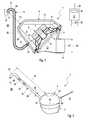
- FIGS. 1 to 3 comprises a sound generator 1, which is responsible for an in FIG. 3 partially shown exhaust system 2 of an internal combustion engine, not shown in a FIG. 3 recognizable vehicle 3 is provided, a housing 4, in which at least one electro-acoustic transducer 5, for example in Shape of a speaker, is arranged.
- the transducer 5 has a diaphragm 6, a diaphragm drive 7 and a cage 8.
- the diaphragm 6 separates in the housing 4 a back volume 9 from a pre-volume 10.
- the diaphragm drive 7 operates, for example, electromagnetically and serves to drive the membrane 6.
- the cage 8 biases the Membrane 6 and carries the membrane drive. 7
- the sound generator 1 also has a connection pipe 11, by means of which the sound generator 1 can be connected to an exhaust gas-carrying exhaust pipe 12 of the exhaust system 2.
- the connecting pipe 11 serves for the fluidic and acoustic coupling of the pre-volume 10 with the exhaust pipe 12 and with the interior of the exhaust pipe 12. In this way, sound waves generated by means of the membrane 6, through the pre-volume 10 and through the Connecting pipe 11 enter the exhaust pipe 12 to change there transported sound.
- the housing 4 may have a pot-shaped housing part 13 and a cover-shaped housing part 14, which is firmly attached to it for closing an opening of the cup-shaped housing part 13.
- the transducer 5 are mounted on the cage 8 and the connecting pipe 11 on the cover-shaped housing part 14.
- the cover-shaped housing part 14 defines the pre-volume 10.
- the cup-shaped housing part 13 defines the rear volume. 9
- the sound generator 1 presented here also has a pressure compensation line 15, which has a proximal end 16 and a distal end 17 with respect to the housing 4.
- the pressure equalization line 15 is connected at its proximal end 16 outside to the housing 4 and there by a housing opening 18 fluidly connected to the rear volume 9.
- the distal end 17 is spaced from the housing 4.
- the pressure equalization line 15 has an in FIG. 2 indicated line length 19, which is large compared to a diameter 20.
- the line length 19 is at least ten times greater than the line diameter 20. Due to the large line length 19 can be according to FIG. 1 set a distance 21 for the distal end 17 relative to the housing 4, which is greater than a diameter 22 of the connecting pipe 11 at a pipe end 23 facing away from the housing 4.
- This distance 21 can according to the embodiments of FIGS. 2 and 3 also be bigger than one in FIG. 1 Plotted diameter 24 of the membrane 6.
- this distance 21 may be greater than a in FIG. 2 registered diameter 25 of the housing 4 in the region of the rear volume 9.
- the pressure compensation line 15 may have at least one throttle device 27.
- the throttling device 27 is designed to allow static pressure equalization between the back volume 9 and the environment 26 while hindering dynamic pressure equalization between the back volume 9 and the environment 26 while being permeable to gas.
- the pressure equalization line 15 may include a filter device 28 configured to inhibit the ingress of liquid and / or solid contaminants into the back volume 9 while permeable to gas.
- the pressure equalization line 15 Between their ends 16, 17, the pressure equalization line 15 according to FIG. 2 have a rigid tube 29. Alternatively, according to FIG. 1 between the ends 16, 17 an elastic hose 30 may be provided.
- the sound generator 1 may also be equipped with a control device 31, which is provided for actuating the membrane drive 7.
- the control device 31 is expediently arranged outside the housing 4, for example at a suitable periphery of the vehicle 3.
- a cable strand 32 is provided, which is passed through a housing wall 33 in a suitable manner.
- the wiring harness 32 serves for the power supply and for the electrical control of the membrane drive 7 and optionally further electrical and / or electronic components of the transducer 5 and the sound generator. 1
- the control device 31 has an emergency shutdown 34, which is designed or programmed such that it reduces or preferably interrupts a current supply to the membrane drive 7 when the pre-volume 10 floats with a liquid, preferably until the flooding is over.
- the control device 31 for this purpose can be coupled via corresponding signal lines 35 with a sensor system suitable for this purpose, not shown here.
- the control device 31 can recognize from the current consumption of the membrane drive 7 whether a flooding of the antechamber 10 is present.
- the aforementioned harness 32 can according to FIG. 2 be passed through the housing wall 33 in a conventional manner by means of a cable bushing 36.
- a cable bushing 36 it is according to the in FIG. 1 shown, preferred solution possible to pass the cable strand 32 through the pressure equalization line 15, so that no separate cable bushing 36 is required for the wiring harness 32.
- the wiring harness 32 is passed through the entire pressure equalization line 15.
- vehicle 3 has in a conventional manner an internal combustion engine, not shown here for driving the vehicle 3.
- the vehicle 3 is in FIG. 3 shown in a rear area 38.
- the internal combustion engine is preferably located in a front area, which is not shown here.
- the vehicle 3 has an exhaust system 2, which, however, is partially shown here only in the rear region 38.
- the exhaust system 2 is used in a conventional manner for discharging exhaust gas from the internal combustion engine.
- the vehicle 3 further has an underbody 39, which is located in a conventional manner on a vehicle underside 40, which faces a substrate 41 on which the vehicle 3 is or drives.
- the exhaust system 2 is now arranged, at least in an end section 42 remote from the internal combustion engine, on a bottom bottom side 43 facing the substrate 41. In this end portion 42, the exhaust system 2 on the sound generator 1 and the exhaust pipe 12.
- the exhaust pipe 12 is in this case an end pipe 44, the outlet end 45 opens into an environment 46.
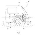
- the pressure equalization line 15 is arranged on the vehicle 3 so that its distal end 17 is located above the housing 4. In the example of FIG. 3 the distal end 17 is disposed on the underbody bottom 43.
- FIGS. 1 to 3 is a distal end portion 47 of the pressure equalization line 15 having the distal end 17, bent so that the distal end 17 is open at the bottom.
- the distal end portion 47 for this purpose has a curved piece 48 which defines an arc of about 180 °.
- the distal end portion 47 is positioned in a wheel well 49.
- the distal end 17 is above a predetermined maximum Waiting depth 50, the in FIG. 3 is indicated by a dashed line. This maximum wading depth 50 may, for example, be spaced 500 mm from the base 41.
- the pressure equalization line 15 can penetrate the subfloor 39 sufficiently sealed, such that the distal end 17 is disposed on a side facing away from the bottom surface 41 top 51.
- the distal end 17 can then open open in a trunk or in a rear compartment or in an interior of the vehicle 3.
- the aforementioned end portion 42 of the exhaust system 2 is at least in the region of the exhaust pipe 12 and thus of the tail pipe 44 and in the region of the housing 4 of the sound generator 1 below the maximum wading depth 50.
- the outlet opening 45 of the tail pipe 44 is likewise arranged below this wading depth 50.
- the exhaust system 2 When driving through a water hole, it can according FIG. 3 Thus come about that on the one hand, the exhaust system 2 is flooded in the region of the end portion 42 from the outside. A possible water level is in Fig. 3 denoted by 52.
- said end section 42 can also be flooded through the end pipe 44 from the inside.
- the flooding from the outside leads to a rapid cooling of the housing 4 and thus to a pressure reduction in the rear volume 9. This pressure reduction can be compensated statically via the pressure equalization line 15, whereby damage to the membrane 6 of the converter 5 can be avoided.
- the flooding of the end region 42 of the exhaust system 2 can also lead to a flooding of the pre-volume 10 from the inside, which can also lead to an undesirable deflection of the membrane 6 in the direction of rear volume 9.
- the control device 31 can detect the flooding of the pilot volume 10 and accordingly react to reduce or interrupt the power supply of the diaphragm drive 7, in order to avoid overheating of the diaphragm drive 7 in this way.
Landscapes
- Engineering & Computer Science (AREA)
- Chemical & Material Sciences (AREA)
- Combustion & Propulsion (AREA)
- Mechanical Engineering (AREA)
- General Engineering & Computer Science (AREA)
- Physics & Mathematics (AREA)
- Acoustics & Sound (AREA)
- Multimedia (AREA)
- Signal Processing (AREA)
- Exhaust Silencers (AREA)
- Cooling, Air Intake And Gas Exhaust, And Fuel Tank Arrangements In Propulsion Units (AREA)
Abstract
Description
- Die vorliegende Erfindung betrifft einen Schallerzeuger für eine Abgasanlage einer Brennkraftmaschine eines Kraftfahrzeugs. Die Erfindung betrifft außerdem ein mit einem derartigen Schallerzeuger ausgestattetes Kraftfahrzeug.
- Ein Schallerzeuger dieser Art besitzt in einem Gehäuse zumindest einen elektroakustischen Wandler, vorzugsweise in Form eines Lautsprechers. Eine Membran des Wandlers trennt im Gehäuse ein Rückvolumen von einem Vorvolumen. Über ein Anschlussrohr kann der Schallerzeuger an eine abgasführende Abgasleitung der Abgasanlage angeschlossen werden, wobei dann das Anschlussrohr im angeschlossenen Zustand das Vorvolumen fluidisch und akustisch mit der Abgasleitung verbindet.
- Ein derartiger Schallerzeuger kann beispielsweise als aktiver Schalldämpfer verwendet werden, um unerwünschte Geräusche zu reduzieren, die sich als Luftschall in der Abgasleitung ausbreiten. Mit Hilfe des elektroakustischen Wandlers wird hierzu entsprechender Gegenschall oder Antischall erzeugt und phasenverschoben abgestrahlt, so dass sich Schall und Antischall überlagern, was zu einer Reduzierung der Amplituden des störenden Schalls führt. Zusätzlich oder alternativ lässt sich ein derartiger Schallerzeuger auch dazu nutzen, gezielt bestimmte Motorgeräusche zu verstärken bzw. zu erzeugen. Auf diese Weise kann mit Hilfe eines derartigen Schallerzeugers der Sound einer Abgasanlage bzw. der Brennkraftmaschine gezielt beeinflusst werden.
- Das im Gehäuse des Schallerzeugers eingeschlossene Rückvolumen besitzt einen Gehäuseinnendruck, der bei ruhender Membran im Wesentlichen mit einem im Vorvolumen herrschenden Außendruck im Gleichgewicht sein muss, damit die Membran ihre neutrale Mittellage einnehmen kann. Damit sich bei Wetteränderungen, die mit einer Änderung des Umgebungsdrucks einhergehen, und bei Temperaturänderungen keine dauerhaften Auslenkungen der Membran aus ihrer Neutrallage einstellen können, die zu einer Beschädigung der Membran führen können, kann das Gehäuse in herkömmlicher Weise mit einer Druckausgleichsöffnung ausgestattet sein, die einen statischen Druckausgleich zwischen dem Rückvolumen und einer Umgebung des Gehäuses ermöglicht. Damit eine derartige Druckausgleichsöffnung nur einen statischen Druckausgleich ermöglicht, während sie einen dynamischen Druckausgleich verhindert, ist eine derartige Druckausgleichsöffnung in der Regel mit einem entsprechend kleinen Öffnungsquerschnitt ausgestattet. Ein statischer Druckausgleich erfolgt üblicherweise mit einer Frequenz von weniger als 1 Hz. Im Unterschied dazu erfolgt ein dynamischer Druckausgleich in der Regel mit einer Frequenz von mehr als 10 Hz. Ein dynamischer Druckausgleich muss vermieden werden, um die Funktionsfähigkeit des Wandlers gewährleisten zu können.
- Damit in einem Fahrzeugbetrieb Spritzwasser nicht durch die Druckausgleichsöffnung in das Gehäuse eindringen kann, ist es grundsätzlich möglich, die Druckausgleichsöffnung mit einem entsprechenden Spritzwasserschutz auszustatten. Ebenso ist denkbar, die Druckausgleichsöffnung mit einer semipermeablen Membran auszustatten, die für Flüssigkeit undurchlässig ist, während sie für Gas durchlässig ist. Die Gasdurchlässigkeit einer derartigen semipermeablen Membran ist dabei so gewählt, dass der erwünschte statische Druckausgleich möglich ist.
- Bei Geländefahrzeugen sowie bei geländefähigen Fahrzeugen, insbesondere bei sogenannten SUVs, wobei es SUV für "Sport Utility Vehicle" steht, besteht außerdem das Problem, dass beim Durchfahren einer Wasserstelle das gesamte Gehäuse des Schallerzeugers von Wasser umspült sein kann. Zwar schützt eine semipermeable Membran auch dann noch vor einem Wassereintritt in das Gehäuse, jedoch kann sie gegen den außen anliegenden Wasserdruck keinen Druckausgleich für das Rückvolumen mehr sicherstellen. Insbesondere ist ein Strömungsweg für Umgebungsluft in das Rückvolumen durch das das Gehäuse umspülende Wasser versperrt. Während eines Normalbetriebs des Fahrzeugs heizt sich die Abgasanlage gegenüber der Umgebung deutlich auf. Insbesondere heizt sich auch das Gehäuse des Schallerzeugers auf. Dabei kann der im Rückvolumen proportional zur Temperatur ansteigende Druck permanent mit der Umgebung ausgeglichen werden, indem Luft aus dem Rückvolumen proportional zur Temperatur durch die Druckausgleichsöffnung in die Umgebung austritt. Durchfährt das Fahrzeug nun eine Wasserstelle, die so tief ist, dass es zu einer Überflutung des Gehäuses kommt, kühlt sich das Gehäuse in kurzer Zeit relativ stark ab, ebenso die im Rückvolumen eingeschlossene Luft. Für einen Druckausgleich müsste nun Luft aus der Umgebung in das Rückvolumen eintreten. Dieser Weg ist jedoch durch das Wasser blockiert, welches das Gehäuse umspült. Somit ist ein statischer Druckausgleich in diesem speziellen Fall nicht möglich. Die Membran wird dabei stark in Richtung Rückvolumen verstellt, wobei es zu einer dauerhaften Beschädigung der Membran kommen kann.
- Des Weiteren kann es beim Durchfahren einer Wasserstelle dazu kommen, dass Wasser durch ein Endrohr der Abgasanlage in diese eindringt und dabei bis zum Schallerzeuger gelangt, wodurch dieser quasi auf der Seite seines Vorvolumens geflutet wird. Der Staudruck des Wassers drückt die Membran dabei ebenfalls in das Rückvolumen hinein. Gegen diesen Staudruck kann ein Membranantrieb des Wandlers die Membran nicht mehr antreiben oder nur noch sehr eingeschränkt. Da in diesem Fall die Leistung des in der Regel elektromagnetischen Membranantriebs nicht in Membranbewegungen gewandelt werden kann, kann es zu einer Überhitzung des Membranantriebs kommen.
- Die vorliegende Erfindung beschäftigt sich mit dem Problem, für einen Schallerzeuger der eingangs genannten Art bzw. für ein damit ausgestattetes Fahrzeug eine verbesserte Ausführungsform anzugeben, die sich insbesondere dadurch auszeichnet, dass die Gefahr einer Beschädigung des Schallerzeugers beim Durchfahren einer Wasserstelle reduziert ist.
- Dieses Problem wird erfindungsgemäß durch die Gegenstände der unabhängigen Ansprüche gelöst. Vorteilhafte Ausführungsformen sind Gegenstand der abhängigen Ansprüche.
- Die Erfindung beruht auf dem allgemeinen Gedanken, das Gehäuse mit einer Druckausgleichsleitung auszustatten, die mit einem proximalen Ende außen an das Gehäuse angeschlossen und dort durch eine Gehäuseöffnung hindurch fluidisch mit dem Rückvolumen verbunden ist, während gleichzeitig ein distales Ende der Druckausgleichsleitung vom Gehäuse beabstandet angeordnet und zur jeweiligen Umgebung offen ist. Durch die Verwendung einer derartigen Druckausgleichsleitung lässt sich bei entsprechender Länge der Druckausgleichsleitung ohne Weiteres das distale Ende der Druckausgleichsleitung so weit oberhalb des Gehäuses positionieren, dass auch bei vollständig überspültem Gehäuse ein Druckausgleich mit der Umgebung möglich ist, da sich das distale Ende der Druckausgleichsleitung auch dann noch oberhalb der Wasserlinie befindet. Die Druckausgleichsleitung funktioniert daher wie eine Art Schnorchel und ermöglicht einen statischen Druckausgleich für das Rückvolumen auch bei vollständig untergetauchtem Gehäuse.
- Gemäß einer vorteilhaften Ausführungsform kann eine Leitungslänge der Druckausgleichsleitung so groß sein, dass für das distale Ende ein Abstand zum Gehäuse einstellbar ist, der größer ist als ein Durchmesser des Anschlussrohrs an einem vom Gehäuse abgewandten Rohrende oder der größer ist als ein Durchmesser der Membran oder der größer ist als ein Durchmesser des Gehäuses im Bereich des Rückvolumens. Somit ist klargestellt, dass die Druckausgleichsleitung deutlich größer dimensioniert ist, als beispielsweise ein Anschlussstutzen, der an das Gehäuse zur Realisierung einer herkömmlichen Druckausgleichsöffnung angebaut sein kann. Durch eine entsprechend gewählte Leitungslänge lässt sich das distale Ende der Druckausgleichsleitung grundsätzlich an jeder beliebigen Stelle innerhalb und außerhalb des Fahrzeugs positionieren. Mit ihrem distalen Ende ist die Druckausgleichsleitung mit einer Umgebung der Druckausgleichsleitung fluidisch verbunden, wodurch insbesondere ein Luftaustausch und somit ein Druckausgleich zwischen dieser Umgebung und dem Rückvolumen möglich ist.
- Bei einer anderen vorteilhaften Ausführungsform kann in der Druckausgleichsleitung wenigstens eine Drosseleinrichtung angeordnet sein, die für das Rückvolumen einen statischen Druckausgleich ermöglicht und einen dynamischen Druckausgleich behindert. Auf diese Weise lässt sich die Druckausgleichsleitung selbst mit einem vergleichsweise großen offenen Querschnitt realisieren, insbesondere derart, dass grundsätzlich auch ein dynamischer Druckausgleich möglich wäre. Die Verwendung einer Drosseleinrichtung ermöglicht dabei das Einstellen einer gezielten Drosselwirkung, wodurch die Druckausgleichsleitung eine erhöhte Funktionssicherheit besitzt. Eine derartige Drosseleinrichtung kann beispielsweise mit Hilfe einer semipermeablen Membran gebildet sein, die für Gas durchlässig und für Flüssigkeit undurchlässig ist.
- Bei einer anderen vorteilhaften Ausführungsform kann in der Druckausgleichsleitung wenigstens eine Filtereinrichtung angeordnet sein, die ein Eindringen von Verunreinigungen in das Rückvolumen behindert. Eine derartige Filtereinrichtung kann beispielsweise durch eine semipermeable Membran gebildet sein. Alternativ kann eine Filtereinrichtung auch durch einen offenporigen Schaumkörper gebildet sein.
- Bei einer anderen vorteilhaften Ausführungsform kann die Druckausgleichsleitung zwischen ihren Enden einen elastischen Schlauch oder ein steifes Rohr aufweisen. Die Verwendung eines elastischen Schlauchs zur Realisierung der Druckausgleichsleitung eröffnet eine vereinfachte Verlegemöglichkeit für die Druckausgleichsleitung am Fahrzeug. Die Verwendung eines steifen Rohrs zur Realisierung der Druckausgleichsleitung kann beispielsweise dazu genutzt werden, das Gehäuse an einer Peripherie des Fahrzeugs zu befestigen.
- Entsprechend einer anderen vorteilhaften Ausführungsform, die auch eine eigenständige Lösung des Problems repräsentieren kann, da sie grundsätzlich auch ohne die vorgenannte Druckausgleichsleitung realisierbar ist, kann eine Steuereinrichtung zum Ansteuern eines Membranantriebs des Lautsprechers vorgesehen sein, die eine Notabschaltung besitzt. Die Notabschaltung ist so konfiguriert, dass sie im Falle einer Flutung des Vorvolumens mit einer Flüssigkeit zu einer Reduzierung oder Unterbrechung einer Stromzufuhr zum Membranantrieb führt. Zweckmäßig wird dabei die Stromzufuhr solange reduziert oder unterbrochen, bis die Flutung vorüber ist. Beispielsweise kann die Steuereinrichtung den Stromverbrauch des Membranantriebs überwachen und anhand eines sich signifikant verändernden Stromverbrauchs eine Flutung des Vorvolumens identifizieren. Ebenso ist es möglich, eine entsprechende Sensorik vorzusehen, die eine Flutung der Abgasanlage identifiziert. Eine derartige Sensorik kann am Fahrzeug ohnehin vorhanden sein. Die Steuereinrichtung des Schallerzeugers kann dann auf entsprechende Weise beispielsweise mit einem Steuergerät des Fahrzeugs verbunden sein, um so die Flutung des Vorraums detektieren zu können.
- Entsprechend einer anderen vorteilhaften Ausführungsform kann ein Kabelstrang zur Stromversorgung und/oder zur elektrischen Ansteuerung wenigstens einer im Rückvolumen angeordneten elektrischen Komponente des Schallerzeugers, wie zum Beispiel eines Membranantriebs, durch die ganze Druckausgleichsleitung oder zumindest durch einen das proximale Ende aufweisenden proximalen Endabschnitt der Druckausgleichsleitung hindurchgeführt sein. Auf diese Weise kann die Druckausgleichsleitung zusätzlich dazu genutzt werden, den Kabelstrang durch eine Gehäusewand hindurchzuführen, so dass auf eine separate Wanddurchführung für den Kabelstrang verzichtet werden kann. Zumindest für den Fall, dass der Kabelstrang durch die ganze Druckausgleichsleitung hindurchgeführt wird, kann auf eine separate Abdichtung für die Kabeldurchführung verzichtet werden, die beispielsweise bei einer separaten Wanddurchführung zwingend erforderlich ist.
- Der hier vorgestellte Schallerzeuger kann als aktiver Schalldämpfer ausgelegt sein, so dass der mit Hilfe des jeweiligen Wandlers generierte Schall bei entsprechender Phasenverschiebung eine Reduzierung der Amplituden unerwünschter Frequenzen von Schall ermöglicht, der sich in der Abgasanlage ausbreitet. Zusätzlich oder alternativ kann der Schallerzeuger auch als Soundgenerator verwendet werden, um gezielt bestimmte Frequenzen zu verstärken bzw. zu erzeugen. Besonders vorteilhaft ist eine kombinierte Anwendung, bei welcher mit Hilfe des Schallerzeugers bei bestimmten Frequenzen die Amplituden mit Antischall reduziert werden, während gleichzeitig bei bestimmten anderen Frequenzen die Amplituden verstärkt bzw. erzeugt werden.
- Ein erfindungsgemäßes Fahrzeug umfasst eine Brennkraftmaschine zum Antreiben des Fahrzeugs sowie eine Abgasanlage zum Abführen von Abgas von der Brennkraftmaschine. Das Fahrzeug besitzt außerdem einen Unterboden, der an einer Fahrzeugunterseite angeordnet ist, die ihrerseits einem Untergrund zugewandt ist, auf dem das Fahrzeug steht oder fährt. Die Abgasanlage ist zumindest in einem von der Brennkraftmaschine entfernten Endabschnitt an einer dem Untergrund zugewandten Unterbodenunterseite angeordnet. Ferner weist die Abgasanlage in ihrem Endabschnitt zumindest einen Schallerzeuger der vorstehend beschriebenen Art auf. Die Abgasanlage besitzt in ihrem Endabschnitt eine abgasführende Abgasleitung, an die das Anschlussrohr des Schallerzeugers angeschlossen ist. Ferner ist vorgesehen, dass die Druckausgleichsleitung des Schallerzeugers mit ihrem distalen Ende oberhalb des Gehäuses des Schallerzeugers am Fahrzeug angeordnet ist.
- Gemäß einer vorteilhaften Ausführungsform kann das distale Ende der Druckausgleichsleitung an der Unterbodenunterseite angeordnet sein, wobei ein das distale Ende aufweisender distaler Endabschnitt der Druckausgleichsleitung so gebogen oder gekrümmt ist, dass das distale Ende nach unten offen ist. Hierdurch ergibt sich ein verbesserter Spritzwasserschutz.
- Gemäß einer vorteilhaften Weiterbildung kann der distale Endabschnitt ein Bogenstück aufweisen, das einen Bogen von mindestens 90° und insbesondere einen Bogen von maximal 180° definiert.
- Sofern das distale Ende der Druckausgleichsleitung an der Unterbodenunterseite angeordnet ist, lässt sich das distale Ende beispielsweise im Bereich eines Radkastens positionieren, und zwar zweckmäßig in einem oberen Bereich des jeweiligen Radkastens. Ferner erfolgt die Positionierung des distalen Endes der Druckausgleichsleitung zweckmäßig oberhalb einer vorbestimmten maximalen Wattiefe, die für das jeweilige Fahrzeug vorgesehen ist. Beispielsweise kann eine Wattiefe von mindestens 500 mm ab dem Untergrund gewünscht sein.
- Bei einer anderen Ausführungsform kann die Druckausgleichsleitung den Unterboden abgedichtet durchdringen, so dass das distale Ende an einer vom Untergrund abgewandten Unterbodenoberseite angeordnet ist. Beispielsweise kann das distale Ende dann in einem heckseitigen Kofferraum des Fahrzeugs oder in einem Innenraum des Fahrzeugs münden. Auf diese Weise ist ein Eindringen von Wasser in die Druckausgleichsleitung nahezu ausgeschlossen.
- Bei einer anderen vorteilhaften Ausführungsform kann der Endabschnitt der Abgasanlage mit der Abgasleitung und mit dem Gehäuse des Schallerzeugers unterhalb einer vorbestimmten maximalen Wattiefe des Fahrzeugs angeordnet sein. Auch das Endrohr kann unterhalb der Wattiefe angeordnet sein. Im Unterschied dazu ist das distale Ende der Druckausgleichsleitung oberhalb der Wattiefe angeordnet.
- Entsprechend einer vorteilhaften Weiterbildung kann die Abgasleitung zu einem zur Umgebung offenen Endrohr der Abgasanlage führen oder durch das Endrohr gebildet sein, das ebenfalls unterhalb der maximalen Wattiefe mündet. In diesem Fall ist es möglich, dass der Endabschnitt der Abgasanlage beim Durchfahren einer Wasserstelle geflutet wird, derart, dass Wasser bis zum Vorraum des Schallerzeugers gelangt.
- Die vorliegende Erfindung betrifft schließlich außerdem ein Verfahren zum Betreiben eines Fahrzeugs der vorstehend beschriebenen Art. Dieses Betriebsverfahren charakterisiert sich dadurch, dass eine Stromzufuhr zu einem Membranantrieb des elektroakustischen Wandlers reduziert oder unterbrochen wird, sobald und solange das Vorvolumen des Gehäuses durch das Endrohr hindurch geflutet wird. Auf diese Weise kann effizient eine Überhitzung des Membranantriebs vermieden werden.
- Weitere wichtige Merkmale und Vorteile der Erfindung ergeben sich aus den Unteransprüchen, aus den Zeichnungen und aus der zugehörigen Figurenbeschreibung anhand der Zeichnungen.
- Es versteht sich, dass die vorstehend genannten und die nachstehend noch zu erläuternden Merkmale nicht nur in der jeweils angegebenen Kombination, sondern auch in anderen Kombinationen oder in Alleinstellung verwendbar sind, ohne den Rahmen der vorliegenden Erfindung zu verlassen.
- Bevorzugte Ausführungsbeispiele der Erfindung sind in den Zeichnungen dargestellt und werden in der nachfolgenden Beschreibung näher erläutert, wobei sich gleiche Bezugszeichen auf gleiche oder ähnliche oder funktional gleiche Komponenten beziehen.
- Es zeigen, jeweils schematisch
- Fig. 1
- eine stark vereinfachte Schnittansicht eines Schallerzeugers,
- Fig. 2
- eine isometrische Ansicht des Schallerzeugers, jedoch bei einer anderen Ausführungsform,
- Fig. 3
- eine stark vereinfachte Seitenansicht eines Fahrzeugs in einem Heckbereich, das mit einem derartigen Schallerzeuger ausgestattet ist.
- Entsprechend den
Figuren 1 bis 3 umfasst ein Schallerzeuger 1, der für eine inFigur 3 teilweise dargestellte Abgasanlage 2 einer nicht dargestellten Brennkraftmaschine eines nur inFigur 3 erkennbaren Fahrzeugs 3 vorgesehen ist, ein Gehäuse 4, in dem zumindest ein elektroakustischer Wandler 5, zum Beispiel in Form eines Lautsprechers, angeordnet ist. Der Wandler 5 besitzt eine Membran 6, einen Membranantrieb 7 und einen Käfig 8. Die Membran 6 trennt im Gehäuse 4 ein Rückvolumen 9 von einem Vorvolumen 10. Der Membranantrieb 7 arbeitet beispielsweise elektromagnetisch und dient zum Antreiben der Membran 6. Der Käfig 8 spannt die Membran 6 auf und trägt den Membranantrieb 7. - Der Schallerzeuger 1 weist außerdem ein Anschlussrohr 11 auf, mit dessen Hilfe der Schallerzeuger 1 an eine abgasführende Abgasleitung 12 der Abgasanlage 2 anschließbar ist. Im angeschlossenen Zustand dient das Anschlussrohr 11 zur fluidischen und akustischen Kopplung des Vorvolumens 10 mit der Abgasleitung 12 bzw. mit dem Inneren der Abgasleitung 12. Auf diese Weise können Schallwellen, die mit Hilfe der Membran 6 erzeugt werden, durch das Vorvolumen 10 und durch das Anschlussrohr 11 in die Abgasleitung 12 gelangen, um dort darin transportierten Schall zu verändern.
- Gemäß
Figur 1 kann das Gehäuse 4 ein topfförmiges Gehäuseteil 13 und ein deckelförmiges Gehäuseteil 14 aufweisen, das zum Verschließen einer Öffnung des topfförmigen Gehäuseteils 13 an dieses fest angebaut ist. Im Beispiel sind der Wandler 5 über dessen Käfig 8 sowie das Anschlussrohr 11 am deckelförmigen Gehäuseteil 14 angebracht. Ferner definiert das deckelförmige Gehäuseteil 14 das Vorvolumen 10. Im Unterschied dazu definiert das topfförmige Gehäuseteil 13 das Rückvolumen 9. - Der hier vorgestellte Schallerzeuger 1 weist außerdem eine Druckausgleichsleitung 15 auf, die bezüglich des Gehäuses 4 ein proximales Ende 16 sowie ein distales Ende 17 aufweist. Die Druckausgleichsleitung 15 ist mit ihrem proximalen Ende 16 außen an das Gehäuse 4 angeschlossen und dort durch eine Gehäuseöffnung 18 hindurch fluidisch mit dem Rückvolumen 9 verbunden. Im Unterschied dazu ist das distale Ende 17 vom Gehäuse 4 beabstandet angeordnet.
- Die Druckausgleichsleitung 15 besitzt eine in
Figur 2 angedeutete Leitungslänge 19, die im Vergleich zu einem Durchmesser 20 groß ist. Insbesondere ist die Leitungslänge 19 mindestens zehnmal größer als der Leitungsdurchmesser 20. Durch die große Leitungslänge 19 lässt sich gemäßFigur 1 für das distale Ende 17 gegenüber dem Gehäuse 4 ein Abstand 21 einstellen, der größer ist als ein Durchmesser 22 des Anschlussrohrs 11 an einem vom Gehäuse 4 abgewandten Rohrende 23. Dieser Abstand 21 kann gemäß den Ausführungsformen derFiguren 2 und 3 auch größer sein als ein inFigur 1 eingezeichneter Durchmesser 24 der Membran 6. Ebenso kann dieser Abstand 21 größer sein als ein inFigur 2 eingetragener Durchmesser 25 des Gehäuses 4 im Bereich des Rückvolumens 9. Somit lässt sich das distale Ende 17, das zu einer Umgebung 26 offen ist, relativ weit vom Gehäuse 4 beabstandet anordnen. - Gemäß
Figur 2 kann die Druckausgleichsleitung 15 zumindest eine Drosseleinrichtung 27 aufweisen. Die Drosseleinrichtung 27 ist so ausgelegt, dass sie einen statischen Druckausgleich zwischen dem Rückvolumen 9 und der Umgebung 26 ermöglicht, während sie einen dynamischen Druckausgleich zwischen dem Rückvolumen 9 und der Umgebung 26 behindert, während sie für Gas durchlässig ist. - Gemäß
Figur 2 kann die Druckausgleichsleitung 15 außerdem eine Filtereinrichtung 28 aufweisen, die so gestaltet ist, dass sie ein Eindringen von flüssigen und/oder festen Verunreinigungen in das Rückvolumen 9 behindert, während sie für Gas durchlässig ist. - Zwischen ihren Enden 16, 17 kann die Druckausgleichsleitung 15 gemäß
Figur 2 ein steifes Rohr 29 aufweisen. Alternativ dazu kann gemäßFigur 1 zwischen den Enden 16, 17 ein elastischer Schlauch 30 vorgesehen sein. - Gemäß
Figur 1 kann der Schallerzeuger 1 außerdem mit einer Steuereinrichtung 31 ausgestattet sein, die zum Ansteuern des Membranantriebs 7 vorgesehen ist. Die Steuereinrichtung 31 ist zweckmäßig außerhalb des Gehäuses 4 angeordnet, beispielsweise an einer geeigneten Peripherie des Fahrzeugs 3. Zur Kopplung der Steuereinrichtung 31 mit dem Membranantrieb 7 ist ein Kabelstrang 32 vorgesehen, der auf geeignete Weise durch eine Gehäusewand 33 hindurchgeführt ist. Der Kabelstrang 32 dient dabei zur Stromversorgung sowie zur elektrischen Ansteuerung des Membranantriebs 7 sowie gegebenenfalls weiterer elektrischer und/oder elektronischer Komponenten des Wandlers 5 bzw. des Schallerzeugers 1. - Die Steuereinrichtung 31 weist eine Notabschaltung 34 auf, die so ausgestaltet bzw. programmiert ist, dass sie bei einer Flutung des Vorvolumens 10 mit einer Flüssigkeit eine Stromzufuhr zum Membranantrieb 7 reduziert oder bevorzugt unterbricht, vorzugsweise solange, bis die Flutung vorüber ist. Beispielsweise kann die Steuereinrichtung 31 hierzu über entsprechende Signalleitungen 35 mit einer hierzu geeigneten, hier nicht gezeigten Sensorik gekoppelt sein. Ebenso kann die Steuereinrichtung 31 an der Stromaufnahme des Membranantriebs 7 erkennen, ob eine Flutung des Vorraums 10 vorliegt.
- Der zuvor genannte Kabelstrang 32 kann gemäß
Figur 2 auf konventionelle Weise mit Hilfe einer Kabeldurchführung 36 durch die Gehäusewand 33 dicht hindurchgeführt sein. Alternativ ist es gemäß der inFigur 1 gezeigten, bevorzugten Lösung möglich, den Kabelstrang 32 durch die Druckausgleichsleitung 15 hindurchzuführen, so dass keine separate Kabeldurchführung 36 für den Kabelstrang 32 erforderlich ist. InFigur 1 ist der Kabelstrang 32 durch die ganze Druckausgleichsleitung 15 hindurchgeführt. Grundsätzlich ist auch denkbar, den Kabelstrang 32 nur durch einen Teil der Druckausgleichsleitung 15 hindurchzuführen, vorzugsweise zumindest durch einen das proximale Ende 16 aufweisenden proximalen Endabschnitt 37 der Druckausgleichsleitung 15. - Das in
Figur 3 gezeigt Fahrzeug 3 besitzt in üblicher Weise eine hier nicht dargestellte Brennkraftmaschine zum Antreiben des Fahrzeugs 3. Das Fahrzeug 3 ist inFigur 3 in einem Heckbereich 38 dargestellt. Die Brennkraftmaschine befindet sich vorzugsweise in einem Frontbereich, der hier jedoch nicht dargestellt ist. Wie erwähnt weist das Fahrzeug 3 eine Abgasanlage 2 auf, die hier jedoch nur im Heckbereich 38 teilweise dargestellt ist. Die Abgasanlage 2 dient in üblicher Weise zum Abführen von Abgas von der Brennkraftmaschine. - Das Fahrzeug 3 besitzt ferner einen Unterboden 39, der sich in üblicher Weise an einer Fahrzeugunterseite 40 befindet, die einem Untergrund 41 zugewandt ist, auf dem das Fahrzeug 3 steht bzw. fährt. Die Abgasanlage 2 ist nun zumindest in einem von der Brennkraftmaschine entfernten Endabschnitt 42 an einer dem Untergrund 41 zugewandten Unterbodenunterseite 43 angeordnet. In diesem Endabschnitt 42 weist die Abgasanlage 2 den Schallerzeuger 1 auf sowie die Abgasleitung 12 auf. Die Abgasleitung 12 ist im vorliegenden Fall ein Endrohr 44, dessen Austrittsende 45 in eine Umgebung 46 mündet. Die Druckausgleichsleitung 15 ist am Fahrzeug 3 so angeordnet, dass sich ihr distales Ende 17 oberhalb des Gehäuses 4 befindet. Im Beispiel der
Figur 3 ist das distale Ende 17 an der Unterbodenunterseite 43 angeordnet. - Gemäß den
Figuren 1 bis 3 ist ein distaler Endabschnitt 47 der Druckausgleichsleitung 15, der das distale Ende 17 aufweist, so gebogen, dass das distale Ende 17 nach unten offen ist. Im Beispiel weist der distale Endabschnitt 47 hierzu ein Bogenstück 48 auf, das einen Bogen von etwa 180° definiert. Im Beispiel derFigur 3 ist der distale Endabschnitt 47 in einem Radkasten 49 positioniert. Jedenfalls befindet sich das distale Ende 17 oberhalb einer vorbestimmten maximalen Warttiefe 50, die inFigur 3 durch eine strichpunktierte Linie angedeutet ist. Diese maximale Wattiefe 50 kann beispielsweise 500 mm vom Untergrund 41 beabstandet sein. - Bei einer hier nicht gezeigten alternativen Ausführungsform kann die Druckausgleichsleitung 15 den Unterboden 39 hinreichend abgedichtet durchdringen, derart, dass das distale Ende 17 an einer vom Untergrund 41 abgewandten Unterbodenoberseite 51 angeordnet ist. Beispielsweise kann das distale Ende 17 dann offen in einem Kofferraum oder in einem Heckraum oder in einem Innenraum des Fahrzeugs 3 münden.
- Wie sich
Figur 3 entnehmen lässt, ist der zuvor genannte Endabschnitt 42 der Abgasanlage 2 zumindest im Bereich der Abgasleitung 12 und somit des Endrohrs 44 sowie im Bereich des Gehäuses 4 des Schallerzeugers 1 unterhalb der maximalen Wattiefe 50 angeordnet. Insbesondere ist die Austrittsöffnung 45 des Endrohrs 44 ebenfalls unterhalb dieser Wattiefe 50 angeordnet. - Beim Durchfahren einer Wasserstelle kann es gemäß
Figur 3 somit dazu kommen, dass zum einen die Abgasanlage 2 im Bereich des Endabschnitts 42 von außen überflutet wird. Ein möglicher Wasserstand ist inFig. 3 mit 52 bezeichnet. Zum anderen kann besagter Endabschnitt 42 durch das Endrohr 44 hindurch auch von innen geflutet werden. Die Überflutung von außen führt zu einer raschen Abkühlung des Gehäuses 4 und somit zu einem Druckabbau im Rückvolumen 9. Dieser Druckabbau kann über die Druckausgleichsleitung 15 statisch ausgeglichen werden, wodurch eine Beschädigung der Membran 6 des Wandlers 5 vermieden werden kann. Die Flutung des Endbereichs 42 der Abgasanlage 2 kann auch zu einer Flutung des Vorvolumens 10 von innen führen, was ebenfalls zu einer unerwünschten Auslenkung der Membran 6 in Richtung Rückvolumen 9 führen kann. Gravierender ist in diesem Fall jedoch, dass der Membranantrieb 7 bei geflutetem Vorvolumen 10 die Membran 6 nicht mehr antreiben kann, wodurch der Membranantrieb 7 überhitzen kann. Wie weiter oben erläutert, kann die Steuereinrichtung 31 das Fluten des Vorvolumens 10 erkennen und dementsprechend zum Reduzieren bzw. zum Unterbrechen der Stromversorgung des Membranantriebs 7 reagieren, um auf diese Weise eine Überhitzung des Membranantriebs 7 zu vermeiden.
Claims (14)
- Schallerzeuger für eine Abgasanlage (2) einer Brennkraftmaschine eines Kraftfahrzeugs (3),- mit einem Gehäuse (4),- mit wenigstens einem im Gehäuse (4) angeordneten elektroakustischen Wandler (5), dessen Membran (6) im Gehäuse (4) ein Rückvolumen (9) von einem Vorvolumen (10) trennt,- mit einem Anschlussrohr (11) zum Anschließen des Schallerzeugers (1) an eine abgasführende Abgasleitung (12) der Abgasanlage (2),- wobei das Anschlussrohr (11) im angeschlossenen Zustand das Vorvolumen (10) fluidisch und akustisch mit der Abgasleitung (12) verbindet,gekennzeichnet durch eine Druckausgleichsleitung (15), die mit einem proximalen Ende (16) außen an das Gehäuse (4) angeschlossen und dort durch eine Gehäuseöffnung (18) hindurch fluidisch mit dem Rückvolumen (9) verbunden ist, wobei ein distales Ende (17) der Druckausgleichsleitung (15) vom Gehäuse (4) beabstandet angeordnet ist.
- Schallerzeuger nach Anspruch 1,
dadurch gekennzeichnet,
dass eine Leitungslänge (19) der Druckausgleichsleitung (15) so groß ist, dass für das distale Ende (17) ein Abstand (21) zum Gehäuse (4) einstellbar ist, der größer ist als ein Durchmesser (22) des Anschlussrohrs (11) an einem vom Gehäuse (4) abgewandten Rohrende (23) oder als ein Durchmesser (24) der Membran (6) oder als ein Durchmesser (25) des Gehäuses (4) im Bereich des Rückvolumens (9). - Schallerzeuger nach Anspruch 1 oder 2,
dadurch gekennzeichnet,
dass in der Druckausgleichsleitung (15) wenigstens eine Drosseleinrichtung (27) angeordnet ist, die für das Rückvolumen (9) einen statischen Druckausgleich ermöglicht und einen dynamischen Druckausgleich behindert. - Schallerzeuger nach einem der Ansprüche 1 bis 3,
dadurch gekennzeichnet,
dass in der Druckausgleichsleitung (15) wenigstens eine Filtereinrichtung (28) angeordnet ist, die ein Eindringen von Verunreinigungen in das Rückvolumen (9) behindert. - Schallerzeuger nach einem der Ansprüche 1 bis 4,
dadurch gekennzeichnet,
dass die Druckausgleichsleitung (15) zwischen ihren Enden (16, 17) einen elastischen Schlauch (30) oder ein steifes Rohr (29) aufweist. - Schallerzeuger nach einem der Ansprüche 1 bis 5,
dadurch gekennzeichnet,
dass eine Steuereinrichtung (31) zum Ansteuern eines Membranantriebs (7) des elektroakustischen Wandlers (5) eine Notabschaltung (34) aufweist, die bei einer Flutung des Vorvolumens (10) mit einer Flüssigkeit eine Stromzufuhr zum Membranantrieb (7) reduziert oder unterbricht bis die Flutung vorüber ist. - Schallerzeuger nach einem der Ansprüche 1 bis 6,
dadurch gekennzeichnet,
dass ein Kabelstrang (32) zur Stromversorgung und/oder elektrischen Ansteuerung wenigstens einer im Rückvolumen (9) angeordneten elektrischen Komponente (7) des Schallerzeugers (1) durch die ganze Druckausgleichsleitung (15) oder zumindest durch einen das proximale Ende (16) aufweisenden proximalen Endabschnitt (37) der Druckausgleichsleitung (15) hindurchgeführt ist. - Fahrzeug, insbesondere Personenkraftwagen,- mit einer Abgasanlage (2) zum Abführen von Abgas von einer Brennkraftmaschine des Fahrzeugs (3),- mit einem Unterboden (39), der an einer Fahrzeugunterseite (40) angeordnet ist, die einem Untergrund (41) zugewandt ist, auf dem das Fahrzeug (3) steht oder fährt,- wobei die Abgasanlage (2) zumindest in einem von der Brennkraftmaschine entfernten Endabschnitts (42) an einer dem Untergrund (41) zugewandten Unterbodenunterseite (43) angeordnet ist,- wobei die Abgasanlage (2) in ihrem Endabschnitt (42) wenigstens einen Schallerzeuger (1) nach einem der Ansprüche 1 bis 7 aufweist,- wobei die Abgasanlage (2) in ihrem Endabschnitt (42) eine abgasführende Abgasleitung (12) aufweist, an die das Anschlussrohr (11) des Schallerzeugers (1) angeschlossen ist,- wobei die Druckausgleichsleitung (15) mit ihrem distalen Ende (17) oberhalb des Gehäuses (4) des Schallerzeugers (1) angeordnet ist.
- Fahrzeug nach Anspruch 8,
dadurch gekennzeichnet,- dass das distale Ende (17) der Druckausgleichsleitung (15) an der Unterbodenunterseite (43) angeordnet ist,- dass ein das distale Ende (17) aufweisender distaler Endabschnitt (47) der Druckausgleichsleitung (15) gebogen ist, so dass das distale Ende (17) nach unten offen ist. - Fahrzeug nach Anspruch 9,
dadurch gekennzeichnet,
dass der distale Endabschnitt (47) ein Bogenstück (48) aufweist, das einen Bogen von mindestens 90° definiert. - Fahrzeug nach Anspruch 8,
dadurch gekennzeichnet,
dass die Druckausgleichsleitung (15) den Unterboden (39) durchdringt, so dass das distale Ende (17) an einer vom Untergrund (41) abgewandten Unterbodenoberseite (51) angeordnet ist. - Fahrzeug nach einem der Ansprüche 8 bis 11,
dadurch gekennzeichnet,
dass der Endabschnitt (42) der Abgasanlage (2) mit der Abgasleitung (12) und mit dem Gehäuse (4) des Schallerzeugers (1) unterhalb einer vorbestimmten maximalen Wattiefe (50) des Fahrzeugs (3) angeordnet ist, während das distale Ende (17) der Druckausgleichsleitung (15) oberhalb der Wattiefe (50) angeordnet ist. - Fahrzeug nach Anspruch 12,
dadurch gekennzeichnet,
dass die Abgasleitung (12) zu einem zur Umgebung (46) offenen Endrohr (44) der Abgasanlage (2) führt oder durch das Endrohr (44) gebildet ist, das ebenfalls unterhalb der maximalen Wattiefe (50) mündet. - Verfahren zum Betreiben eines Fahrzeugs (3) nach Anspruch 13, bei dem eine Stromzufuhr zu einem Membranantrieb (7) des elektroakustischen Wandlers (5) reduziert oder unterbrochen wird, sobald und solange das Vorvolumen (10) des Gehäuses (4) durch das Endrohr (44) hindurch geflutet wird.
Applications Claiming Priority (1)
| Application Number | Priority Date | Filing Date | Title |
|---|---|---|---|
| DE102013208186.3A DE102013208186B4 (de) | 2013-05-03 | 2013-05-03 | Schallerzeuger für eine Abgasanlage |
Publications (3)
| Publication Number | Publication Date |
|---|---|
| EP2800090A2 true EP2800090A2 (de) | 2014-11-05 |
| EP2800090A3 EP2800090A3 (de) | 2015-04-15 |
| EP2800090B1 EP2800090B1 (de) | 2017-09-06 |
Family
ID=50542859
Family Applications (1)
| Application Number | Title | Priority Date | Filing Date |
|---|---|---|---|
| EP14165579.5A Not-in-force EP2800090B1 (de) | 2013-05-03 | 2014-04-23 | Schallerzeuger für eine Abgasanlage |
Country Status (5)
| Country | Link |
|---|---|
| US (1) | US9462363B2 (de) |
| EP (1) | EP2800090B1 (de) |
| JP (1) | JP5791754B2 (de) |
| CN (1) | CN104131862B (de) |
| DE (1) | DE102013208186B4 (de) |
Cited By (2)
| Publication number | Priority date | Publication date | Assignee | Title |
|---|---|---|---|---|
| DE102017203183B4 (de) | 2017-02-28 | 2021-09-02 | Audi Ag | Klangerzeugungsvorrichtung zur Erzeugung von Abgasanlagensound sowie ein zugehöriges Kraftfahrzeug |
| DE102019002654B4 (de) | 2019-04-11 | 2023-02-16 | Paragon Gmbh & Co. Kgaa | "Lautsprecher für Kraftfahrzeuge" |
Families Citing this family (14)
| Publication number | Priority date | Publication date | Assignee | Title |
|---|---|---|---|---|
| DE102013104810A1 (de) * | 2013-05-08 | 2014-11-13 | Eberspächer Exhaust Technology GmbH & Co. KG | Schallerzeuger für ein antischall-system zur beeinflussung von abgasgeräuschen und/oder ansauggeräuschen eines kraftfahrzeugs |
| DE102014113940A1 (de) | 2014-09-25 | 2016-03-31 | Eberspächer Exhaust Technology GmbH & Co. KG | Überlastungsschutz für einen Aktor eines Systems zur Beeinflussung von in einer Abgasanlage geführtem Schall |
| GB2535731B (en) * | 2015-02-25 | 2019-05-08 | Jaguar Land Rover Ltd | Active noise control for vehicles |
| GB201513555D0 (en) | 2015-07-31 | 2015-09-16 | Pss Belgium Nv | Audio system |
| DE102015119191A1 (de) | 2015-11-06 | 2017-05-11 | Eberspächer Exhaust Technology GmbH & Co. KG | Schallerzeuger zur Befestigung an einem Fahrzeug zur Beeinflussung von Geräuschen des Fahrzeugs |
| EP3436752B1 (de) | 2016-03-30 | 2021-06-30 | Marine Canada Acquisition Inc. | Fahrzeugheizgerät und steuerungen dafür |
| US10017008B1 (en) * | 2017-06-16 | 2018-07-10 | Liang Fei Industry Co., Ltd. | Subsidiary loudspeaker for vehicles and bikes |
| DE102017113878A1 (de) * | 2017-06-22 | 2018-12-27 | Eberspächer Exhaust Technology GmbH & Co. KG | Schallerzeugungsbaugruppe |
| US10724410B1 (en) | 2017-11-14 | 2020-07-28 | Brunswick Corporation | Exhaust sound enhancement assembly and method for a marine propulsion device |
| DE102017127454A1 (de) * | 2017-11-21 | 2019-05-23 | Faurecia Emissions Control Technologies, Germany Gmbh | Schallerzeugungsvorrichtung sowie Fahrzeugabgasanlage |
| US10699693B1 (en) * | 2019-07-08 | 2020-06-30 | Hyundai Motor Company | Sound generator for vehicle |
| DE202020005760U1 (de) | 2019-08-27 | 2022-06-10 | Limited Liability Company "Car Systems" | System zur Simulation der von einer Auspuffanlage wiedergegebenen Motorgeräusche eines Fahrzeugs |
| KR102750739B1 (ko) * | 2020-05-25 | 2025-01-06 | 현대자동차주식회사 | 음파 증폭장치 |
| DE102022131534A1 (de) | 2022-11-29 | 2024-05-29 | Bayerische Motoren Werke Aktiengesellschaft | Abführeinrichtung zum Abführen von Kondensat aus einer Abgasanlage, Abgasanlage sowie Kraftfahrzeug |
Family Cites Families (13)
| Publication number | Priority date | Publication date | Assignee | Title |
|---|---|---|---|---|
| JPS5973517U (ja) * | 1982-11-08 | 1984-05-18 | 日産自動車株式会社 | 自動車用内燃機関の排気消音装置 |
| US5097923A (en) * | 1988-02-19 | 1992-03-24 | Noise Cancellation Technologies, Inc. | Active sound attenation system for engine exhaust systems and the like |
| KR950004674B1 (ko) * | 1992-05-28 | 1995-05-04 | 아시아자동차공업주식회사 | 이동식 액체용기의 에어브리더용 액체누출 방지장치 |
| US5408221A (en) * | 1993-07-27 | 1995-04-18 | Inventech, Inc. | Downed water skier warning system |
| JP3223727B2 (ja) * | 1994-11-08 | 2001-10-29 | 日本鋼管株式会社 | 粉粒体切出し移送装置 |
| WO2000011312A1 (en) * | 1998-08-19 | 2000-03-02 | Songdo Technopark | Grouting pipe equipment and method of grouting using the same for an underground water well |
| EP1059830A3 (de) * | 1999-05-19 | 2003-12-17 | Faurecia Abgastechnik GmbH | Elektrodynamischer Lautsprecher mit einer Regeleinrichtung für einen aktiven Kraftfahrzeug-Schalldämpfer |
| FR2803625B1 (fr) * | 2000-01-10 | 2002-05-03 | Ecia Equip Composants Ind Auto | Systeme d'echappement d'un moteur thermique comportant un capteur de son |
| DE102008018085A1 (de) * | 2008-04-09 | 2009-10-15 | J. Eberspächer GmbH & Co. KG | Aktiver Schalldämpfer |
| DE102009011516A1 (de) * | 2009-03-06 | 2010-09-16 | Kautex Textron Gmbh & Co. Kg | Betriebsflüssigkeitsbehälter |
| US9227479B2 (en) * | 2011-03-15 | 2016-01-05 | Jaguar Land Rover Limited | Wading vehicle control system |
| DE102011084567C5 (de) * | 2011-10-14 | 2019-08-14 | Eberspächer Exhaust Technology GmbH & Co. KG | Aktiver Schalldämpfer |
| DE102011089283A1 (de) * | 2011-12-20 | 2013-06-20 | Bayerische Motoren Werke Aktiengesellschaft | Aktoranordnung für aktive Abgasanlagen und Verfahren zum Betreiben derselben |
-
2013
- 2013-05-03 DE DE102013208186.3A patent/DE102013208186B4/de not_active Expired - Fee Related
-
2014
- 2014-04-23 EP EP14165579.5A patent/EP2800090B1/de not_active Not-in-force
- 2014-04-30 JP JP2014093878A patent/JP5791754B2/ja not_active Expired - Fee Related
- 2014-04-30 CN CN201410182128.4A patent/CN104131862B/zh not_active Expired - Fee Related
- 2014-05-02 US US14/268,074 patent/US9462363B2/en active Active
Non-Patent Citations (1)
| Title |
|---|
| None |
Cited By (2)
| Publication number | Priority date | Publication date | Assignee | Title |
|---|---|---|---|---|
| DE102017203183B4 (de) | 2017-02-28 | 2021-09-02 | Audi Ag | Klangerzeugungsvorrichtung zur Erzeugung von Abgasanlagensound sowie ein zugehöriges Kraftfahrzeug |
| DE102019002654B4 (de) | 2019-04-11 | 2023-02-16 | Paragon Gmbh & Co. Kgaa | "Lautsprecher für Kraftfahrzeuge" |
Also Published As
| Publication number | Publication date |
|---|---|
| JP5791754B2 (ja) | 2015-10-07 |
| EP2800090B1 (de) | 2017-09-06 |
| EP2800090A3 (de) | 2015-04-15 |
| DE102013208186A1 (de) | 2014-11-06 |
| CN104131862A (zh) | 2014-11-05 |
| JP2014219003A (ja) | 2014-11-20 |
| DE102013208186B4 (de) | 2016-09-22 |
| US9462363B2 (en) | 2016-10-04 |
| US20140328493A1 (en) | 2014-11-06 |
| CN104131862B (zh) | 2017-06-09 |
Similar Documents
| Publication | Publication Date | Title |
|---|---|---|
| EP2800090B1 (de) | Schallerzeuger für eine Abgasanlage | |
| EP2623737B1 (de) | Aktiver Schalldämpfer | |
| DE4435296C2 (de) | Kraftfahrzeug mit einer Brennkraftmaschine | |
| EP3143777B1 (de) | Mems-lautsprecher mit aktuatorstruktur und davon beabstandeter membran | |
| EP2817175B1 (de) | Lautsprechersystem für ein kraftfahrzeug | |
| EP2581567B1 (de) | Aktiver Schalldämpfer | |
| EP2817174B1 (de) | Lautsprechersystem für ein kraftfahrzeug | |
| EP2617956B1 (de) | Abgasvorrichtung für eine Brennkraftmaschine | |
| DE102011007854A1 (de) | Abgasanlagenkomponente | |
| DE102008016579A1 (de) | Brennstoffzelleneinrichtung und Verfahren zum Betreiben einer Brennstoffzelleneinrichtung | |
| EP2891775A1 (de) | Abgasanlage mit einem System zur Abfuhr von Kondensat | |
| DE102012101145A1 (de) | Vorrichtung zur aktiven Geräuschsteuerung eines Ansaugsystems eines Fahrzeuges | |
| DE10144972C1 (de) | Fluidführung, insbesondere in Form eines Rohluftschlauchs zum Einsaugen von Rohluft in einen Luftfilter eines Kraftfahrzeuges | |
| DE112011103989T5 (de) | Auslassventil in Kombination mit einem aktiven Geräuschdämpfungssystem | |
| DE102016002687A1 (de) | Vorrichtung zur Verminderung von Heckscheiben-Geräusch | |
| EP1507682B1 (de) | Vorrichtung zur geräuschgestaltung bei einem kraftfahrzeug | |
| EP2138700A2 (de) | Luftfilter und damit ausgestattete Frischluftanlage | |
| DE102017129245A1 (de) | Lufteinlassvorrichtung für eine Kühlvorrichtung eines Elektrofahrzeugs | |
| DE102009060081B4 (de) | Vakuumabwassersystemschalldämpfer | |
| DE102009023890A1 (de) | Vorrichtung zur Reduzierung von Wummergeräuschen bei einem Kraftfahrzeug | |
| DE102017126883A1 (de) | Arbeitsfahrzeug mit Lärmreduzierung in einer Fahrerkabine | |
| DE102010023649A1 (de) | Membranversteifung durch Verrippung für die Vorrichtung zur Übertragung des Motorengeräusches | |
| WO2003049493A1 (de) | Displayfenster zur schallabstrahlung in kommunikations- und multimediageräten | |
| EP2476871A2 (de) | Auspuffanordnung zur Verwendung mit einem Verbrennungsmotor | |
| DE102017127454A1 (de) | Schallerzeugungsvorrichtung sowie Fahrzeugabgasanlage |
Legal Events
| Date | Code | Title | Description |
|---|---|---|---|
| PUAI | Public reference made under article 153(3) epc to a published international application that has entered the european phase |
Free format text: ORIGINAL CODE: 0009012 |
|
| 17P | Request for examination filed |
Effective date: 20140423 |
|
| AK | Designated contracting states |
Kind code of ref document: A2 Designated state(s): AL AT BE BG CH CY CZ DE DK EE ES FI FR GB GR HR HU IE IS IT LI LT LU LV MC MK MT NL NO PL PT RO RS SE SI SK SM TR |
|
| AX | Request for extension of the european patent |
Extension state: BA ME |
|
| PUAL | Search report despatched |
Free format text: ORIGINAL CODE: 0009013 |
|
| AK | Designated contracting states |
Kind code of ref document: A3 Designated state(s): AL AT BE BG CH CY CZ DE DK EE ES FI FR GB GR HR HU IE IS IT LI LT LU LV MC MK MT NL NO PL PT RO RS SE SI SK SM TR |
|
| AX | Request for extension of the european patent |
Extension state: BA ME |
|
| RIC1 | Information provided on ipc code assigned before grant |
Ipc: G10K 11/178 20060101AFI20150310BHEP Ipc: F01N 1/06 20060101ALI20150310BHEP |
|
| R17P | Request for examination filed (corrected) |
Effective date: 20151007 |
|
| RBV | Designated contracting states (corrected) |
Designated state(s): AL AT BE BG CH CY CZ DE DK EE ES FI FR GB GR HR HU IE IS IT LI LT LU LV MC MK MT NL NO PL PT RO RS SE SI SK SM TR |
|
| REG | Reference to a national code |
Ref country code: DE Ref legal event code: R079 Ref document number: 502014005301 Country of ref document: DE Free format text: PREVIOUS MAIN CLASS: G10K0011178000 Ipc: F01N0013080000 |
|
| GRAP | Despatch of communication of intention to grant a patent |
Free format text: ORIGINAL CODE: EPIDOSNIGR1 |
|
| RIC1 | Information provided on ipc code assigned before grant |
Ipc: F01N 13/08 20100101AFI20170322BHEP Ipc: F01N 1/06 20060101ALI20170322BHEP Ipc: F01N 13/18 20100101ALI20170322BHEP |
|
| INTG | Intention to grant announced |
Effective date: 20170411 |
|
| GRAS | Grant fee paid |
Free format text: ORIGINAL CODE: EPIDOSNIGR3 |
|
| GRAA | (expected) grant |
Free format text: ORIGINAL CODE: 0009210 |
|
| AK | Designated contracting states |
Kind code of ref document: B1 Designated state(s): AL AT BE BG CH CY CZ DE DK EE ES FI FR GB GR HR HU IE IS IT LI LT LU LV MC MK MT NL NO PL PT RO RS SE SI SK SM TR |
|
| REG | Reference to a national code |
Ref country code: GB Ref legal event code: FG4D Free format text: NOT ENGLISH |
|
| REG | Reference to a national code |
Ref country code: CH Ref legal event code: EP Ref country code: AT Ref legal event code: REF Ref document number: 926160 Country of ref document: AT Kind code of ref document: T Effective date: 20170915 |
|
| REG | Reference to a national code |
Ref country code: IE Ref legal event code: FG4D Free format text: LANGUAGE OF EP DOCUMENT: GERMAN |
|
| REG | Reference to a national code |
Ref country code: DE Ref legal event code: R096 Ref document number: 502014005301 Country of ref document: DE |
|
| REG | Reference to a national code |
Ref country code: SE Ref legal event code: TRGR |
|
| REG | Reference to a national code |
Ref country code: NL Ref legal event code: MP Effective date: 20170906 |
|
| REG | Reference to a national code |
Ref country code: LT Ref legal event code: MG4D |
|
| PG25 | Lapsed in a contracting state [announced via postgrant information from national office to epo] |
Ref country code: HR Free format text: LAPSE BECAUSE OF FAILURE TO SUBMIT A TRANSLATION OF THE DESCRIPTION OR TO PAY THE FEE WITHIN THE PRESCRIBED TIME-LIMIT Effective date: 20170906 Ref country code: NO Free format text: LAPSE BECAUSE OF FAILURE TO SUBMIT A TRANSLATION OF THE DESCRIPTION OR TO PAY THE FEE WITHIN THE PRESCRIBED TIME-LIMIT Effective date: 20171206 Ref country code: LT Free format text: LAPSE BECAUSE OF FAILURE TO SUBMIT A TRANSLATION OF THE DESCRIPTION OR TO PAY THE FEE WITHIN THE PRESCRIBED TIME-LIMIT Effective date: 20170906 Ref country code: FI Free format text: LAPSE BECAUSE OF FAILURE TO SUBMIT A TRANSLATION OF THE DESCRIPTION OR TO PAY THE FEE WITHIN THE PRESCRIBED TIME-LIMIT Effective date: 20170906 |
|
| PG25 | Lapsed in a contracting state [announced via postgrant information from national office to epo] |
Ref country code: ES Free format text: LAPSE BECAUSE OF FAILURE TO SUBMIT A TRANSLATION OF THE DESCRIPTION OR TO PAY THE FEE WITHIN THE PRESCRIBED TIME-LIMIT Effective date: 20170906 Ref country code: LV Free format text: LAPSE BECAUSE OF FAILURE TO SUBMIT A TRANSLATION OF THE DESCRIPTION OR TO PAY THE FEE WITHIN THE PRESCRIBED TIME-LIMIT Effective date: 20170906 Ref country code: GR Free format text: LAPSE BECAUSE OF FAILURE TO SUBMIT A TRANSLATION OF THE DESCRIPTION OR TO PAY THE FEE WITHIN THE PRESCRIBED TIME-LIMIT Effective date: 20171207 Ref country code: BG Free format text: LAPSE BECAUSE OF FAILURE TO SUBMIT A TRANSLATION OF THE DESCRIPTION OR TO PAY THE FEE WITHIN THE PRESCRIBED TIME-LIMIT Effective date: 20171206 Ref country code: RS Free format text: LAPSE BECAUSE OF FAILURE TO SUBMIT A TRANSLATION OF THE DESCRIPTION OR TO PAY THE FEE WITHIN THE PRESCRIBED TIME-LIMIT Effective date: 20170906 |
|
| PG25 | Lapsed in a contracting state [announced via postgrant information from national office to epo] |
Ref country code: NL Free format text: LAPSE BECAUSE OF FAILURE TO SUBMIT A TRANSLATION OF THE DESCRIPTION OR TO PAY THE FEE WITHIN THE PRESCRIBED TIME-LIMIT Effective date: 20170906 |
|
| REG | Reference to a national code |
Ref country code: FR Ref legal event code: PLFP Year of fee payment: 5 |
|
| PG25 | Lapsed in a contracting state [announced via postgrant information from national office to epo] |
Ref country code: RO Free format text: LAPSE BECAUSE OF FAILURE TO SUBMIT A TRANSLATION OF THE DESCRIPTION OR TO PAY THE FEE WITHIN THE PRESCRIBED TIME-LIMIT Effective date: 20170906 Ref country code: CZ Free format text: LAPSE BECAUSE OF FAILURE TO SUBMIT A TRANSLATION OF THE DESCRIPTION OR TO PAY THE FEE WITHIN THE PRESCRIBED TIME-LIMIT Effective date: 20170906 Ref country code: PL Free format text: LAPSE BECAUSE OF FAILURE TO SUBMIT A TRANSLATION OF THE DESCRIPTION OR TO PAY THE FEE WITHIN THE PRESCRIBED TIME-LIMIT Effective date: 20170906 |
|
| PG25 | Lapsed in a contracting state [announced via postgrant information from national office to epo] |
Ref country code: IS Free format text: LAPSE BECAUSE OF FAILURE TO SUBMIT A TRANSLATION OF THE DESCRIPTION OR TO PAY THE FEE WITHIN THE PRESCRIBED TIME-LIMIT Effective date: 20180106 Ref country code: SM Free format text: LAPSE BECAUSE OF FAILURE TO SUBMIT A TRANSLATION OF THE DESCRIPTION OR TO PAY THE FEE WITHIN THE PRESCRIBED TIME-LIMIT Effective date: 20170906 Ref country code: EE Free format text: LAPSE BECAUSE OF FAILURE TO SUBMIT A TRANSLATION OF THE DESCRIPTION OR TO PAY THE FEE WITHIN THE PRESCRIBED TIME-LIMIT Effective date: 20170906 Ref country code: SK Free format text: LAPSE BECAUSE OF FAILURE TO SUBMIT A TRANSLATION OF THE DESCRIPTION OR TO PAY THE FEE WITHIN THE PRESCRIBED TIME-LIMIT Effective date: 20170906 |
|
| REG | Reference to a national code |
Ref country code: DE Ref legal event code: R097 Ref document number: 502014005301 Country of ref document: DE |
|
| PLBE | No opposition filed within time limit |
Free format text: ORIGINAL CODE: 0009261 |
|
| STAA | Information on the status of an ep patent application or granted ep patent |
Free format text: STATUS: NO OPPOSITION FILED WITHIN TIME LIMIT |
|
| PG25 | Lapsed in a contracting state [announced via postgrant information from national office to epo] |
Ref country code: DK Free format text: LAPSE BECAUSE OF FAILURE TO SUBMIT A TRANSLATION OF THE DESCRIPTION OR TO PAY THE FEE WITHIN THE PRESCRIBED TIME-LIMIT Effective date: 20170906 |
|
| 26N | No opposition filed |
Effective date: 20180607 |
|
| PG25 | Lapsed in a contracting state [announced via postgrant information from national office to epo] |
Ref country code: SI Free format text: LAPSE BECAUSE OF FAILURE TO SUBMIT A TRANSLATION OF THE DESCRIPTION OR TO PAY THE FEE WITHIN THE PRESCRIBED TIME-LIMIT Effective date: 20170906 |
|
| PGFP | Annual fee paid to national office [announced via postgrant information from national office to epo] |
Ref country code: IT Payment date: 20180420 Year of fee payment: 5 |
|
| PG25 | Lapsed in a contracting state [announced via postgrant information from national office to epo] |
Ref country code: MT Free format text: LAPSE BECAUSE OF FAILURE TO SUBMIT A TRANSLATION OF THE DESCRIPTION OR TO PAY THE FEE WITHIN THE PRESCRIBED TIME-LIMIT Effective date: 20170906 |
|
| PG25 | Lapsed in a contracting state [announced via postgrant information from national office to epo] |
Ref country code: MC Free format text: LAPSE BECAUSE OF FAILURE TO SUBMIT A TRANSLATION OF THE DESCRIPTION OR TO PAY THE FEE WITHIN THE PRESCRIBED TIME-LIMIT Effective date: 20170906 |
|
| REG | Reference to a national code |
Ref country code: CH Ref legal event code: PL |
|
| REG | Reference to a national code |
Ref country code: BE Ref legal event code: MM Effective date: 20180430 |
|
| REG | Reference to a national code |
Ref country code: IE Ref legal event code: MM4A |
|
| PG25 | Lapsed in a contracting state [announced via postgrant information from national office to epo] |
Ref country code: LU Free format text: LAPSE BECAUSE OF NON-PAYMENT OF DUE FEES Effective date: 20180423 |
|
| PG25 | Lapsed in a contracting state [announced via postgrant information from national office to epo] |
Ref country code: LI Free format text: LAPSE BECAUSE OF NON-PAYMENT OF DUE FEES Effective date: 20180430 Ref country code: CH Free format text: LAPSE BECAUSE OF NON-PAYMENT OF DUE FEES Effective date: 20180430 Ref country code: BE Free format text: LAPSE BECAUSE OF NON-PAYMENT OF DUE FEES Effective date: 20180430 |
|
| PG25 | Lapsed in a contracting state [announced via postgrant information from national office to epo] |
Ref country code: IE Free format text: LAPSE BECAUSE OF NON-PAYMENT OF DUE FEES Effective date: 20180423 |
|
| PG25 | Lapsed in a contracting state [announced via postgrant information from national office to epo] |
Ref country code: TR Free format text: LAPSE BECAUSE OF FAILURE TO SUBMIT A TRANSLATION OF THE DESCRIPTION OR TO PAY THE FEE WITHIN THE PRESCRIBED TIME-LIMIT Effective date: 20170906 |
|
| PG25 | Lapsed in a contracting state [announced via postgrant information from national office to epo] |
Ref country code: IT Free format text: LAPSE BECAUSE OF NON-PAYMENT OF DUE FEES Effective date: 20190423 |
|
| PG25 | Lapsed in a contracting state [announced via postgrant information from national office to epo] |
Ref country code: HU Free format text: LAPSE BECAUSE OF FAILURE TO SUBMIT A TRANSLATION OF THE DESCRIPTION OR TO PAY THE FEE WITHIN THE PRESCRIBED TIME-LIMIT; INVALID AB INITIO Effective date: 20140423 Ref country code: PT Free format text: LAPSE BECAUSE OF FAILURE TO SUBMIT A TRANSLATION OF THE DESCRIPTION OR TO PAY THE FEE WITHIN THE PRESCRIBED TIME-LIMIT Effective date: 20170906 |
|
| PG25 | Lapsed in a contracting state [announced via postgrant information from national office to epo] |
Ref country code: MK Free format text: LAPSE BECAUSE OF NON-PAYMENT OF DUE FEES Effective date: 20170906 Ref country code: CY Free format text: LAPSE BECAUSE OF FAILURE TO SUBMIT A TRANSLATION OF THE DESCRIPTION OR TO PAY THE FEE WITHIN THE PRESCRIBED TIME-LIMIT Effective date: 20170906 |
|
| PG25 | Lapsed in a contracting state [announced via postgrant information from national office to epo] |
Ref country code: AL Free format text: LAPSE BECAUSE OF FAILURE TO SUBMIT A TRANSLATION OF THE DESCRIPTION OR TO PAY THE FEE WITHIN THE PRESCRIBED TIME-LIMIT Effective date: 20170906 |
|
| REG | Reference to a national code |
Ref country code: AT Ref legal event code: MM01 Ref document number: 926160 Country of ref document: AT Kind code of ref document: T Effective date: 20190423 |
|
| PG25 | Lapsed in a contracting state [announced via postgrant information from national office to epo] |
Ref country code: AT Free format text: LAPSE BECAUSE OF NON-PAYMENT OF DUE FEES Effective date: 20190423 |
|
| REG | Reference to a national code |
Ref country code: DE Ref legal event code: R081 Ref document number: 502014005301 Country of ref document: DE Owner name: PUREM GMBH, DE Free format text: FORMER OWNER: EBERSPAECHER EXHAUST TECHNOLOGY GMBH & CO. KG, 66539 NEUNKIRCHEN, DE |
|
| PGFP | Annual fee paid to national office [announced via postgrant information from national office to epo] |
Ref country code: SE Payment date: 20220422 Year of fee payment: 9 |
|
| REG | Reference to a national code |
Ref country code: SE Ref legal event code: EUG |
|
| PG25 | Lapsed in a contracting state [announced via postgrant information from national office to epo] |
Ref country code: SE Free format text: LAPSE BECAUSE OF NON-PAYMENT OF DUE FEES Effective date: 20230424 |
|
| PGFP | Annual fee paid to national office [announced via postgrant information from national office to epo] |
Ref country code: GB Payment date: 20240423 Year of fee payment: 11 |
|
| PGFP | Annual fee paid to national office [announced via postgrant information from national office to epo] |
Ref country code: DE Payment date: 20240418 Year of fee payment: 11 |
|
| PGFP | Annual fee paid to national office [announced via postgrant information from national office to epo] |
Ref country code: FR Payment date: 20240422 Year of fee payment: 11 |
|
| REG | Reference to a national code |
Ref country code: DE Ref legal event code: R119 Ref document number: 502014005301 Country of ref document: DE |
|
| GBPC | Gb: european patent ceased through non-payment of renewal fee |
Effective date: 20250423 |
|
| PG25 | Lapsed in a contracting state [announced via postgrant information from national office to epo] |
Ref country code: DE Free format text: LAPSE BECAUSE OF NON-PAYMENT OF DUE FEES Effective date: 20251104 |
|
| PG25 | Lapsed in a contracting state [announced via postgrant information from national office to epo] |
Ref country code: GB Free format text: LAPSE BECAUSE OF NON-PAYMENT OF DUE FEES Effective date: 20250423 |
|
| PG25 | Lapsed in a contracting state [announced via postgrant information from national office to epo] |
Ref country code: FR Free format text: LAPSE BECAUSE OF NON-PAYMENT OF DUE FEES Effective date: 20250430 |