EP2799849A1 - Nmr imaging device and nmr imaging method - Google Patents
Nmr imaging device and nmr imaging method Download PDFInfo
- Publication number
- EP2799849A1 EP2799849A1 EP12860186.1A EP12860186A EP2799849A1 EP 2799849 A1 EP2799849 A1 EP 2799849A1 EP 12860186 A EP12860186 A EP 12860186A EP 2799849 A1 EP2799849 A1 EP 2799849A1
- Authority
- EP
- European Patent Office
- Prior art keywords
- sample
- pulse
- relaxation time
- time interval
- nmr
- Prior art date
- Legal status (The legal status is an assumption and is not a legal conclusion. Google has not performed a legal analysis and makes no representation as to the accuracy of the status listed.)
- Granted
Links
Images


Classifications
-
- G—PHYSICS
- G01—MEASURING; TESTING
- G01R—MEASURING ELECTRIC VARIABLES; MEASURING MAGNETIC VARIABLES
- G01R33/00—Arrangements or instruments for measuring magnetic variables
- G01R33/20—Arrangements or instruments for measuring magnetic variables involving magnetic resonance
- G01R33/44—Arrangements or instruments for measuring magnetic variables involving magnetic resonance using nuclear magnetic resonance [NMR]
- G01R33/48—NMR imaging systems
- G01R33/50—NMR imaging systems based on the determination of relaxation times, e.g. T1 measurement by IR sequences; T2 measurement by multiple-echo sequences
-
- G—PHYSICS
- G01—MEASURING; TESTING
- G01N—INVESTIGATING OR ANALYSING MATERIALS BY DETERMINING THEIR CHEMICAL OR PHYSICAL PROPERTIES
- G01N24/00—Investigating or analyzing materials by the use of nuclear magnetic resonance, electron paramagnetic resonance or other spin effects
- G01N24/08—Investigating or analyzing materials by the use of nuclear magnetic resonance, electron paramagnetic resonance or other spin effects by using nuclear magnetic resonance
-
- G—PHYSICS
- G01—MEASURING; TESTING
- G01R—MEASURING ELECTRIC VARIABLES; MEASURING MAGNETIC VARIABLES
- G01R33/00—Arrangements or instruments for measuring magnetic variables
- G01R33/20—Arrangements or instruments for measuring magnetic variables involving magnetic resonance
- G01R33/28—Details of apparatus provided for in groups G01R33/44 - G01R33/64
- G01R33/32—Excitation or detection systems, e.g. using radio frequency signals
- G01R33/34—Constructional details, e.g. resonators, specially adapted to MR
-
- G—PHYSICS
- G01—MEASURING; TESTING
- G01R—MEASURING ELECTRIC VARIABLES; MEASURING MAGNETIC VARIABLES
- G01R33/00—Arrangements or instruments for measuring magnetic variables
- G01R33/20—Arrangements or instruments for measuring magnetic variables involving magnetic resonance
- G01R33/44—Arrangements or instruments for measuring magnetic variables involving magnetic resonance using nuclear magnetic resonance [NMR]
- G01R33/48—NMR imaging systems
- G01R33/54—Signal processing systems, e.g. using pulse sequences ; Generation or control of pulse sequences; Operator console
- G01R33/56—Image enhancement or correction, e.g. subtraction or averaging techniques, e.g. improvement of signal-to-noise ratio and resolution
-
- H—ELECTRICITY
- H10—SEMICONDUCTOR DEVICES; ELECTRIC SOLID-STATE DEVICES NOT OTHERWISE PROVIDED FOR
- H10P—GENERIC PROCESSES OR APPARATUS FOR THE MANUFACTURE OR TREATMENT OF DEVICES COVERED BY CLASS H10
- H10P74/00—Testing or measuring during manufacture or treatment of wafers, substrates or devices
- H10P74/20—Testing or measuring during manufacture or treatment of wafers, substrates or devices characterised by the properties tested or measured, e.g. structural or electrical properties
- H10P74/203—Structural properties, e.g. testing or measuring thicknesses, line widths, warpage, bond strengths or physical defects
Definitions
- This invention relates to an NMR imaging device and an NMR imaging method.
- Nuclear magnetic resonance is a phenomenon that a resonance occurs between a magnetic field and an atomic nucleus when a nuclear spin that is precessing in the magnetic field is applied with a rotating magnetic field having the same frequency as a Larmor frequency of the precession.
- an oscillating magnetic field resonating in a pulse-like manner is applied to a nuclear spin directed to be parallel or antiparallel to a magnetic field in a static magnetic field, the static magnetic field is applied in a center axis (Z axis) direction, so as to change the spin direction in an XY axis direction.
- a period of time for the spin direction to return to the original direction is referred to as "a relaxation time" is measured so as to identify the bonding structure or the physical properties of the object to be measured.
- the relaxation time includes a vertical relaxation time T 1 that is a relaxation time of a component in a center axis direction (Z axis direction) of the spin precession before the pulse is introduced, and a transverse relaxation time T 2 that is a relaxation time of a component in a direction (XY axis direction) perpendicular to the center axis direction.
- a measurement result of this nuclear spin relaxation state is imaged to be a magnetic resonance image (MRI).
- the bonding structure or the physical properties of the object to be measured are imaged based on the vertical relaxation time T 1 and/or the transverse relaxation time T 2 .
- Patent Document 1 when imaging is performed based on the transverse relaxation time T 2 , a method of measuring T 2 by Hahn echo is usually adopted (Patent Document 1).
- Patent Document 1 JP-A-H10-277006
- T 2 H T 2 H
- T 2 H is affected by static noise received by the object to be measured. Therefore, there is a problem in that a difference of T 2 H is so small that it becomes difficult to distinguish substances by MRI, depending on a bonding state of the object to be measured or an external environment.
- the difference of T 2 H becomes smaller as a difference of an electron density of the object to be measured becomes smaller in a case where the object to be measured is a semiconductor substrate. Therefore, it may be difficult to distinguish by MRI a substance such as a semiconductor in which different impurities are doped.
- This invention has been made in view of the above-mentioned problem, and an object thereof is to provide an NMR imaging device capable of distinguishing substances that cannot be distinguished by T 2 H .
- the inventors of this invention found after keen examination that there is a predetermined relationship between a signal attenuation constant T 2 L (generalized transverse relaxation time) of an NMR signal in a case where a ⁇ pulse is applied to the object to be measured at a predetermined interval (in a multiplexed manner) and dynamic noise received by the spin of the object to be measured from an external environment.
- T 2 L generally transverse relaxation time
- the inventors found that it is possible to realize the MRI capable of clearly distinguishing the object to be measured that cannot be distinguished by T 2 H , in which the relaxation characteristics reflecting not the static noise due to the external environment but dynamic noise are extracted through imaging of T 2 L by applying the ⁇ pulse signal to the sample at a predetermined time interval considering noise received by nuclear species of the object to be measured from the external environment.
- this invention has been made.
- an NMR imaging device which comprises:
- an NMR imaging method which comprises the steps of:
- the NMR imaging device capable of distinguishing substances that cannot be distinguished by T 2 H .
- a magnetic pulse (here, ⁇ pulse) is applied to a sample as an object to be measured.
- the magnetic pulse having a Larmor frequency corresponding to a static magnetic field at a point to be measured.
- a pulse applying interval is 2 ⁇ in this embodiment.
- ⁇ means a half time of a ⁇ pulse interval, that is, the pulse applying interval (see FIG. 1 ).
- a signal attenuation constant (here, referred to as a generalized transverse relaxation time) T 2 L depends on the ⁇ pulse interval 2 ⁇ , and further, the following relationship (2) is satisfied between the ⁇ pulse interval 2 ⁇ and a frequency f related to measurement among frequencies of noise received by a nuclear spin from an external environment (fluctuation of fluctuating magnetic field).
- f 1 4 ⁇ ⁇ f : frequency of noise received by nuclear spin ⁇ : (a half of) ⁇ pulse interval.
- noise contributing to the generalized transverse relaxation time T 2 L is limited to one satisfying the relationship (2). Therefore, by changing the ⁇ pulse interval 2 ⁇ so as to obtain the NMR signal, it is possible to measure a spectrum of the noise.
- the ⁇ pulse having a predetermined pulse interval considering the noise received by the nuclear species of the object to be measured from the external environment is introduced to the sample, so as to obtain the generalized transverse relaxation time T 2 L for performing imaging.
- the NMR imaging device 1 includes a probe 3 configured to house the object to be measured, to which a static gradient magnetic field is applied (the sample can be housed in the static gradient magnetic field), an application portion 5 configured to apply the magnetic pulse to the probe 3, and an image processing portion 7 configured to perform imaging of the generalized transverse relaxation time T 2 L based on the nuclear magnetic resonance signal output from the sample.
- FIG. 2 a coil for applying the static magnetic field and the static gradient magnetic field, an amplifier for amplifying the magnetic pulse, a cooling device for cooling the device, and the like are not illustrated.
- the object to be measured is placed in the probe 3 illustrated in FIG. 2 , and the static gradient magnetic field is applied by using the coil (not shown) and the like, while the magnetic pulse is introduced into the probe 3 by using the application portion 5 so that the sample is applied with the multiplexed ⁇ pulse (S1 in FIG. 3 ).
- the ⁇ pulse interval 2 ⁇ in this case is determined in accordance with the external environment of the sample considering the noise sensed by the nuclear species of the object to be measured (received from the external environment). Specifically, if the sample is a semiconductor as an example described later, for example, the ⁇ pulse interval 2 ⁇ corresponding to a frequency range in which an interaction between carriers and the nuclear spins causes noise is selected.
- the ⁇ pulse interval 2 ⁇ corresponding to a frequency range supporting a biological reaction and a response speed of a specific part of an organ is selected.
- the signal attenuation constant T 2 L is determined from the NMR signal (S2 in FIG. 3 ).
- the sample applied with the multiplexed ⁇ pulse outputs the NMR signal.
- a predetermined period of time elapses in other words, a sufficient number of ⁇ pulses are introduced
- a logarithm of intensity of the NMR signal is attenuated in proportion to time as shown in FIG. 4 (see expression (1)).
- the image processing portion 7 performs imaging of T 2 L by expressing a length of the generalized transverse relaxation time T 2 L with density of color, for example (S3 in FIG. 3 ).
- the NMR imaging device 1 applies the ⁇ pulse to the sample at the predetermined time interval 2 ⁇ in a multiplexed manner so as to perform imaging of the generalized (transverse) relaxation time based on the nuclear magnetic resonance signal of the sample.
- the MRI imaging suitable for the object to be measured can be performed by selecting the ⁇ pulse interval 2 ⁇ corresponding to the object to be measured.
- the second embodiment is an example in which an image of generalized relaxation time is obtained by changing a measurement position and the ⁇ pulse interval 2 ⁇ with respect to the object to be measured in the first embodiment.
- the NMR imaging device 1 used in the second embodiment is the same as that used in the first embodiment, and therefore a description thereof is omitted.
- the object to be measured is placed in the probe 3 illustrated in FIG. 2 , and the static gradient magnetic field is applied by using the coil (not shown) or the like (S21 in FIG. 10 ).
- the interval 2 ⁇ of the multiplexed ⁇ pulse to be applied to the sample namely a frequency of the dynamic noise f to be measured is determined (S22 in FIG. 10 ).
- the measurement position corresponding to a gradient of the applied magnetic field is determined (S23 in FIG. 10 ). Specifically, a frequency and a phase of an RF magnetic field are determined.
- the magnetic pulse is introduced into the probe 3, and the multiplexed ⁇ pulse is applied to the sample at the interval 2 ⁇ determined in Step S22 (S24 in FIG. 10 ).
- the generalized transverse relaxation time T 2 L is determined from the NMR signal (S25 in FIG. 10 ).
- Step S23 (S26 in FIG. 10 ), and the measurement position is determined again. In accordance with the number of positions to be measured, Steps S23 to S25 are repeated.
- the generalized transverse relaxation time T 2 L of the sample corresponding to the frequency of the dynamic noise f determined in Step S22 is determined (S27 in FIG. 10 ).
- Step S22 (S28 in FIG. 10 ), and the multiplexed ⁇ pulse interval 2 ⁇ is determined again. Steps S22 to S27 are repeated in accordance with the number of frequencies to be measured.
- the measurement position and the ⁇ pulse interval 2 ⁇ may be variable.
- the image of the generalized transverse relaxation time T 2 L can be obtained at various measurement positions and ⁇ pulse intervals 2 ⁇ for the same object to be measured, and hence characteristics of the object to be measured can be understood in more detail.
- the NMR imaging device 1 applies the ⁇ pulse to the sample at a predetermined time interval 2 ⁇ in a multiplexed manner, so as to perform imaging of the generalized (transverse) relaxation time based on the nuclear magnetic resonance signal of the sample.
- the NMR imaging device 1 can obtain the image of the generalized transverse relaxation time T 2 L at various measurement positions and ⁇ pulse intervals 2 ⁇ .
- characteristics of the object to be measured can be understood in more detail.
- the nuclear magnetic resonance was generated by using the multiplexed ⁇ pulse so as to perform imaging of the generalized transverse relaxation time T 2 L , and the result was compared to a case where the imaging of the signal attenuation constant T 2 H corresponding to the static transverse relaxation time was performed by using the Hahn echo that was used in a related-art MRI.
- a proton used for the MRI of a living body has a sensitivity of at least 200 times of that of As (because sensitivity is proportional to cube of nuclear gyromagnetic ratio in theory).
- the generalized transverse relaxation time T 2 L can be determined for a living body sample having dimensions sufficiently smaller than 1 mm3.
- the nuclear magnetic resonance device has been manufactured by the applicant et al, which includes an Oxford room temperature bore high resolution NMR superconducting magnet (Oxford 300/89 made in UK), an RF signal generator (HP8656B made in USA), a DC pulse programmer (THAMWAY Corp, N210-1026S made in Japan), a programmable attenuator (TAMAGAWA ELECTRONICS, TPA-410 made in Japan), an RF power amplifier (Doty DSI1000B made in USA), an RF preamplifier (Doty 2L Series made in USA), and the like.
- the sample was set in the nuclear magnetic resonance device illustrated in FIG. 2 so as to introduce the multiplexed ⁇ pulse to the sample in the static magnetic field, and the generalized transverse relaxation time T 2 L of 75 As was determined from the NMR signal.
- the multiplexed ⁇ pulse was introduced to the sample, and temporal change of intensity of the NMR signal output from the sample was plotted on a logarithm graph as shown in FIGS. 4 to 6 .
- the ⁇ pulse interval 2 ⁇ was set to be 100 ⁇ s as an interval corresponding to the frequency range in which the interaction between the carriers and the nuclear spins significantly affects noise.
- T 2 L obtained in the example is the same as that in the actual MRI.
- nuclear magnetic resonance was generated in the above-mentioned three types of samples by using the Hahn echo, and the signal attenuation constant T 2 H was obtained.
- the measurement condition was entirely the same as that of the multiplexed pulse measurement except that the number of accumulation times was 64 and that the signal intensity of the spin echo was measured as a function of ⁇ for first two pulses of the pulse application in FIG. 1 (general Hahn echo measurement).
- the sample was set to have a flat square shape of dimensions of 5 mm by 5 mm (having a thickness of 1 mm), and simulation of imaging was performed for the samples arranged in 3x3 in the layout illustrated in FIG. 7 .
- the T 2 L imaged image of this example is shown in FIG. 8
- the T 2 H imaged image of the comparative example is shown in FIG. 9
- the imaged image is a gray scale image in which the color density becomes higher as a value of T 2 H or T 2 L is larger (gradation).
- T 2 H there was a difference of value of T 2 H between GaAs (Si-doped) having a large electron density of 10 18 cm -2 and GaAs (undoped) having insulation as well as GaAs (Cr-doped).
- T 2 H of GaAs (undoped) was 220 ⁇ s
- T 2 H of GaAs (Cr-doped) was 230 ⁇ s, and a difference therebetween was very small (10 ⁇ s order). Therefore, it was difficult to distinguish between the two samples by T 2 H based on Hahn echo.
- this invention can be applied to 1 H (proton) or 13 C imaging that is widely used for a living body and in medical MRI.
- frequencies of noise that can be detected by the current pulse technology are 100 Hz to a few kHz order, and the frequencies are overlapped with a biological reaction and a response speed of a small part of an organ. Also from this viewpoint, it is expected that it is advantageous to apply this invention to 1 H (proton) or 13 C imaging.
Landscapes
- Physics & Mathematics (AREA)
- High Energy & Nuclear Physics (AREA)
- General Physics & Mathematics (AREA)
- Condensed Matter Physics & Semiconductors (AREA)
- Health & Medical Sciences (AREA)
- General Health & Medical Sciences (AREA)
- Analytical Chemistry (AREA)
- Life Sciences & Earth Sciences (AREA)
- Chemical & Material Sciences (AREA)
- Biochemistry (AREA)
- Immunology (AREA)
- Pathology (AREA)
- Radiology & Medical Imaging (AREA)
- Engineering & Computer Science (AREA)
- Signal Processing (AREA)
- Nuclear Medicine, Radiotherapy & Molecular Imaging (AREA)
- Magnetic Resonance Imaging Apparatus (AREA)
Abstract
Description
- This invention relates to an NMR imaging device and an NMR imaging method.
- Nuclear magnetic resonance (NMR) is a phenomenon that a resonance occurs between a magnetic field and an atomic nucleus when a nuclear spin that is precessing in the magnetic field is applied with a rotating magnetic field having the same frequency as a Larmor frequency of the precession.
- Because relaxation characteristics for the nuclear spin to return to an original state after changing the state due to the resonance are different depending on a situation of the nuclear spin, it is possible to identify a bonding structure or physical properties of an object to be measured.
- More specifically, for example, an oscillating magnetic field resonating in a pulse-like manner is applied to a nuclear spin directed to be parallel or antiparallel to a magnetic field in a static magnetic field, the static magnetic field is applied in a center axis (Z axis) direction, so as to change the spin direction in an XY axis direction. After that, a period of time for the spin direction to return to the original direction (the period of time is referred to as "a relaxation time") is measured so as to identify the bonding structure or the physical properties of the object to be measured.
- Further, the relaxation time includes a vertical relaxation time T1 that is a relaxation time of a component in a center axis direction (Z axis direction) of the spin precession before the pulse is introduced, and a transverse relaxation time T2 that is a relaxation time of a component in a direction (XY axis direction) perpendicular to the center axis direction.
- A measurement result of this nuclear spin relaxation state is imaged to be a magnetic resonance image (MRI). The bonding structure or the physical properties of the object to be measured are imaged based on the vertical relaxation time T1 and/or the transverse relaxation time T2.
- Here, when imaging is performed based on the transverse relaxation time T2, a method of measuring T2 by Hahn echo is usually adopted (Patent Document 1).
- Patent Document 1:
JP-A-H10-277006 - However, when imaging is performed by measuring T2(T2 H) by Hahn echo, T2 H is affected by static noise received by the object to be measured. Therefore, there is a problem in that a difference of T2 H is so small that it becomes difficult to distinguish substances by MRI, depending on a bonding state of the object to be measured or an external environment.
- Specifically, for example, the difference of T2 H becomes smaller as a difference of an electron density of the object to be measured becomes smaller in a case where the object to be measured is a semiconductor substrate. Therefore, it may be difficult to distinguish by MRI a substance such as a semiconductor in which different impurities are doped.
- This invention has been made in view of the above-mentioned problem, and an object thereof is to provide an NMR imaging device capable of distinguishing substances that cannot be distinguished by T2 H.
- In order to achieve the above-mentioned object, the inventors of this invention found after keen examination that there is a predetermined relationship between a signal attenuation constant T2 L (generalized transverse relaxation time) of an NMR signal in a case where a π pulse is applied to the object to be measured at a predetermined interval (in a multiplexed manner) and dynamic noise received by the spin of the object to be measured from an external environment.
- Further, the inventors found that it is possible to realize the MRI capable of clearly distinguishing the object to be measured that cannot be distinguished by T2 H, in which the relaxation characteristics reflecting not the static noise due to the external environment but dynamic noise are extracted through imaging of T2 L by applying the π pulse signal to the sample at a predetermined time interval considering noise received by nuclear species of the object to be measured from the external environment. Thus, this invention has been made.
- According to a first aspect of this invention, there is provided an NMR imaging device, which comprises:
- a probe capable of housing a sample in a static gradient magnetic field;
- an application portion configured to apply a π pulse to the sample in a multiplexed manner at a predetermined time interval, the π pulse having a Larmor frequency corresponding to the static gradient magnetic field at a predetermined position of the sample; and
- an image processing portion configured to determine a relaxation time based on a nuclear magnetic resonance (NMR) signal of the sample, and to perform imaging of the relaxation time. In the first aspect of this invention, the NMR signal and the relaxation time have a relationship shown in the following expression (1). The predetermined time interval of the π pulse and a frequency of noise are expressed by the following expression (2).
- According to a second aspect of this invention, there is provided an NMR imaging method, which comprises the steps of:
- (a) placing a sample in a static gradient magnetic field;
- (b) applying a π pulse to the sample in a multiplexed manner at a predetermined time interval, the π pulse having a Larmor frequency corresponding to the static gradient magnetic field at a predetermined position of the sample; and
- (c) determining a relaxation time based on a nuclear magnetic resonance signal of the sample, and performing imaging of the relaxation time. In the second aspect of this invention, the nuclear magnetic resonance signal and the relaxation time have a relationship shown in the following expression (1). The predetermined time interval of the π pulse and the noise are expressed by the following expression (2).
- According to this invention, it is possible to provide the NMR imaging device capable of distinguishing substances that cannot be distinguished by T2 H.
-
-
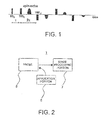
FIG. 1 is a view showing an example of a multiplexed π pulse for use in this invention. -
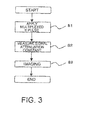
FIG. 2 is a schematic diagram illustrating a structure of anNMR imaging device 1 according to a first embodiment of this invention. -
FIG. 3 is a flowchart illustrating an operation of theNMR imaging device 1. -
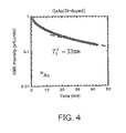
FIG. 4 is a graph showing a relationship between an NMR signal and time when the multiplexed π pulse shown inFIG. 1 is applied to Si-doped GaAs in an example of this invention. -
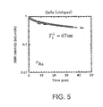
FIG. 5 is a graph showing a relationship between the NMR signal and time when the multiplexed π pulse shown inFIG. 1 is applied to undoped GaAs in the example. -
FIG. 6 is a graph showing a relationship between the NMR signal and time when the multiplexed π pulse shown inFIG. 1 is applied to Cr-doped GaAs in the example. -
FIG. 7 is a diagram illustrating a layout shape and dimensions of the sample on a plane in the example and a comparative example. -
FIG. 8 is a view showing a T2 L image ofFIG. 7 in the example. -
FIG. 9 is a view showing a T2 H image ofFIG. 7 in the comparative example. -
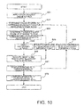
FIG. 10 is a flowchart illustrating a procedure of a second embodiment of this invention. - Now, descriptions will be made as regards embodiments of this invention in detail with reference to the drawings.
- First, a first embodiment of this invention is described.
- To begin with, a principle of nuclear magnetic resonance imaging of this invention is described.
- First, a magnetic pulse (here, π pulse) is applied to a sample as an object to be measured. The magnetic pulse having a Larmor frequency corresponding to a static magnetic field at a point to be measured.
- Specifically, a multiplexed π pulse as shown in
FIG. 1 is applied. A pulse applying interval is 2τ in this embodiment. - Further, τ means a half time of a π pulse interval, that is, the pulse applying interval (see
FIG. 1 ). - In nuclear species of the object to be measured applied with the magnetic pulse, which resonate with the magnetic pulse, a spin direction of the precession changes due to the nuclear magnetic resonance, and then, uniform phases of spins become disturbed while outputting a nuclear magnetic resonance signal (NMR signal). After the π pulse is applied in a multiplexed manner for a sufficiently long period of time (in sufficient amount), the following relationship (1) is satisfied between intensity of the nuclear magnetic resonance signal and time.

W(t): NMR signal intensity
T2 L: signal attenuation constant (relaxation time)
t: time - In this case, a signal attenuation constant (here, referred to as a generalized transverse relaxation time) T2 L depends on the π pulse interval 2τ, and further, the following relationship (2) is satisfied between the π pulse interval 2τ and a frequency f related to measurement among frequencies of noise received by a nuclear spin from an external environment (fluctuation of fluctuating magnetic field).

f : frequency of noise received by nuclear spin
τ : (a half of) π pulse interval. - As understood from the relationships (1) and (2), noise contributing to the generalized transverse relaxation time T2 L is limited to one satisfying the relationship (2). Therefore, by changing the π pulse interval 2τ so as to obtain the NMR signal, it is possible to measure a spectrum of the noise.
- In this invention, utilizing this fact, the π pulse having a predetermined pulse interval considering the noise received by the nuclear species of the object to be measured from the external environment is introduced to the sample, so as to obtain the generalized transverse relaxation time T2 L for performing imaging.
- Next, with reference to
FIG. 2 , a structure of anNMR imaging device 1 according to a first embodiment is described. - As illustrated in
FIG. 2 , theNMR imaging device 1 includes aprobe 3 configured to house the object to be measured, to which a static gradient magnetic field is applied (the sample can be housed in the static gradient magnetic field), anapplication portion 5 configured to apply the magnetic pulse to theprobe 3, and animage processing portion 7 configured to perform imaging of the generalized transverse relaxation time T2 L based on the nuclear magnetic resonance signal output from the sample. - Here, in
FIG. 2 , a coil for applying the static magnetic field and the static gradient magnetic field, an amplifier for amplifying the magnetic pulse, a cooling device for cooling the device, and the like are not illustrated. - Next, with reference to
FIGS. 2 to 4 , an imaging method using theNMR imaging device 1 according to the first embodiment is described. - First, the object to be measured is placed in the
probe 3 illustrated inFIG. 2 , and the static gradient magnetic field is applied by using the coil (not shown) and the like, while the magnetic pulse is introduced into theprobe 3 by using theapplication portion 5 so that the sample is applied with the multiplexed π pulse (S1 inFIG. 3 ). - Further, the π pulse interval 2τ in this case is determined in accordance with the external environment of the sample considering the noise sensed by the nuclear species of the object to be measured (received from the external environment). Specifically, if the sample is a semiconductor as an example described later, for example, the π pulse interval 2τ corresponding to a frequency range in which an interaction between carriers and the nuclear spins causes noise is selected.
- In addition, if the sample is a living body, the π pulse interval 2τ corresponding to a frequency range supporting a biological reaction and a response speed of a specific part of an organ is selected.
- Next, the signal attenuation constant T2 L is determined from the NMR signal (S2 in
FIG. 3 ). - Specifically, the sample applied with the multiplexed π pulse outputs the NMR signal. When a predetermined period of time elapses (in other words, a sufficient number of π pulses are introduced), a logarithm of intensity of the NMR signal is attenuated in proportion to time as shown in
FIG. 4 (see expression (1)). - In this attenuation curve, a proportionality constant (the reciprocal thereof) that is the generalized transverse relaxation time T2 L is determined.
- Finally, the
image processing portion 7 performs imaging of T2 L by expressing a length of the generalized transverse relaxation time T2 L with density of color, for example (S3 inFIG. 3 ). - In this way, according to the first embodiment, the
NMR imaging device 1 applies the π pulse to the sample at the predetermined time interval 2τ in a multiplexed manner so as to perform imaging of the generalized (transverse) relaxation time based on the nuclear magnetic resonance signal of the sample. - Therefore, it is possible to perform imaging while considering a dynamic noise f sensed by the nuclear species of the object to be measured (received from the external environment). Therefore, even if a static noise due to a bonding state of the object to be measured or the external environment is the same, it is possible to distinguish the object.
- In addition, because the π pulse interval 2τ can be controlled in a wide range, the MRI imaging suitable for the object to be measured can be performed by selecting the π pulse interval 2τ corresponding to the object to be measured.
- Next, a second embodiment of this invention is described with reference to
FIG. 10 . - The second embodiment is an example in which an image of generalized relaxation time is obtained by changing a measurement position and the π pulse interval 2τ with respect to the object to be measured in the first embodiment.
- Further, the
NMR imaging device 1 used in the second embodiment is the same as that used in the first embodiment, and therefore a description thereof is omitted. - First, the object to be measured is placed in the
probe 3 illustrated inFIG. 2 , and the static gradient magnetic field is applied by using the coil (not shown) or the like (S21 inFIG. 10 ). - Next, the interval 2τ of the multiplexed π pulse to be applied to the sample, namely a frequency of the dynamic noise f to be measured is determined (S22 in
FIG. 10 ). - Next, the measurement position corresponding to a gradient of the applied magnetic field is determined (S23 in
FIG. 10 ). Specifically, a frequency and a phase of an RF magnetic field are determined. - Next, using the
application portion 5, the magnetic pulse is introduced into theprobe 3, and the multiplexed π pulse is applied to the sample at the interval 2τ determined in Step S22 (S24 inFIG. 10 ). - Next, the generalized transverse relaxation time T2 L is determined from the NMR signal (S25 in
FIG. 10 ). - Thus, the generalized transverse relaxation time T2 L at the measurement position determined in Step S23 is determined.
- Next, in order to determine the generalized transverse relaxation time T2 L at a different measurement position, the flow returns to Step S23 (S26 in
FIG. 10 ), and the measurement position is determined again. In accordance with the number of positions to be measured, Steps S23 to S25 are repeated. - When measurement at every position is finished, the generalized transverse relaxation time T2 L of the sample corresponding to the frequency of the dynamic noise f determined in Step S22 is determined (S27 in
FIG. 10 ). - Next, in order to determine the generalized transverse relaxation time T2 L at a different frequency of the dynamic noise f, the flow returns to Step S22 (S28 in
FIG. 10 ), and the multiplexed π pulse interval 2τ is determined again. Steps S22 to S27 are repeated in accordance with the number of frequencies to be measured. - When measurement at every frequency is finished, finally, an image of the generalized transverse relaxation time T2 L of the sample corresponding to various frequencies determined in Step S22 is determined (S29 in
FIG. 10 ). - In this way, the measurement position and the π pulse interval 2τ may be variable.
- Thus, the image of the generalized transverse relaxation time T2 L can be obtained at various measurement positions and π pulse intervals 2τ for the same object to be measured, and hence characteristics of the object to be measured can be understood in more detail.
- In this way, according to the second embodiment, the
NMR imaging device 1 applies the π pulse to the sample at a predetermined time interval 2τ in a multiplexed manner, so as to perform imaging of the generalized (transverse) relaxation time based on the nuclear magnetic resonance signal of the sample. - Therefore, the same effect as the first embodiment can be obtained.
- In addition, according to the second embodiment, the
NMR imaging device 1 can obtain the image of the generalized transverse relaxation time T2 L at various measurement positions and π pulse intervals 2τ. - Therefore, compared to the first embodiment, characteristics of the object to be measured can be understood in more detail.
- In the following, this invention is specifically described based on an example.
- For each of three types of GaAs, the nuclear magnetic resonance was generated by using the multiplexed π pulse so as to perform imaging of the generalized transverse relaxation time T2 L, and the result was compared to a case where the imaging of the signal attenuation constant T2 H corresponding to the static transverse relaxation time was performed by using the Hahn echo that was used in a related-art MRI.
- First, as samples, three types of materials of substrates were prepared, which include GaAs (undoped), GaAs (Si-doped with a dose of 1018 cm-3), and GaAs (Cr-doped with a dose of 1015 cm-3).
- In this example in which the generalized transverse relaxation time T2 L was determined, an experiment was carried out with such four substrates (each having a thickness of 0.3 mm) that were each cut out to have a size of 10.5 mm by 3.8 mm and stacked.
- Further, a capacity of the sample was large so that the experiment in various parameters was able to be carried out in short time in this example, but it is confirmed that the generalized transverse relaxation time T2 L can be sufficiently determined even if a total amount of target nuclear spins is 1/40 of that at this time.
- Therefore, the proposal of this patent application can be applied to a sample of GaAs of at least 1 mm3.
- Further, a proton used for the MRI of a living body has a sensitivity of at least 200 times of that of As (because sensitivity is proportional to cube of nuclear gyromagnetic ratio in theory).
- Therefore, the generalized transverse relaxation time T2 L can be determined for a living body sample having dimensions sufficiently smaller than 1 mm3.
- Further, the nuclear magnetic resonance device has been manufactured by the applicant et al, which includes an Oxford room temperature bore high resolution NMR superconducting magnet (Oxford 300/89 made in UK), an RF signal generator (HP8656B made in USA), a DC pulse programmer (THAMWAY Corp, N210-1026S made in Japan), a programmable attenuator (TAMAGAWA ELECTRONICS, TPA-410 made in Japan), an RF power amplifier (Doty DSI1000B made in USA), an RF preamplifier (Doty 2L Series made in USA), and the like.
- Next, the sample was set in the nuclear magnetic resonance device illustrated in
FIG. 2 so as to introduce the multiplexed π pulse to the sample in the static magnetic field, and the generalized transverse relaxation time T2 L of 75As was determined from the NMR signal. - Specifically, first, the multiplexed π pulse was introduced to the sample, and temporal change of intensity of the NMR signal output from the sample was plotted on a logarithm graph as shown in
FIGS. 4 to 6 . - Next, from the plotted data, an area in which an initial large attenuation was eliminated so that the logarithm of the intensity of the NMR signal was attenuated in proportion to time was determined and fitted by a straight line as shown by a broken line of
FIGS. 4 to 6 , and hence the signal attenuation constant T2 L was determined from a gradient of the straight line. - Here, not from the first 180° pulse but a time domain is used in which the intensity of the NMR signal is sufficiently attenuated and the signal intensity is fitted by M(t)∼exp(-t/T2L).
- Further, the π pulse interval 2τ was set to be 100 µs as an interval corresponding to the frequency range in which the interaction between the carriers and the nuclear spins significantly affects noise.
- In addition, although the gradient of the static magnetic field is used for obtaining an image in a usual MRI, this experiment was carried out under a constant static magnetic field. This condition is as follows: static magnetic field is 6.16578 T, measuring temperature is 300K, repetition time is 3.0 seconds, and the number of accumulation times is 512 (APCP pulse).
- However, because ununiformity of the static magnetic field does not affect the obtaining of T2 L, T2 L obtained in the example is the same as that in the actual MRI.
- Further, as a comparative example, nuclear magnetic resonance was generated in the above-mentioned three types of samples by using the Hahn echo, and the signal attenuation constant T2 H was obtained. The measurement condition was entirely the same as that of the multiplexed pulse measurement except that the number of accumulation times was 64 and that the signal intensity of the spin echo was measured as a function of τ for first two pulses of the pulse application in
FIG. 1 (general Hahn echo measurement). - Next, based on the obtained T2 L and T2 H, the sample was set to have a flat square shape of dimensions of 5 mm by 5 mm (having a thickness of 1 mm), and simulation of imaging was performed for the samples arranged in 3x3 in the layout illustrated in
FIG. 7 . - Results of calculation of T2 L and T2 H are shown in Table 1.
- In addition, the T2 L imaged image of this example is shown in
FIG. 8 , and the T2 H imaged image of the comparative example is shown inFIG. 9 . Further, the imaged image is a gray scale image in which the color density becomes higher as a value of T2 H or T2 L is larger (gradation).[Table 1] Sample GaAs (Si doped) GaAs (Undoped) GaAs (Cr) doped T2 H 360 µs 230 µs 220 µs T2 L(τ=100 µs) 33 ms 67 ms 94 ms - As understood from Table 1 and
FIG. 8 , a difference of value of T2 L among samples is obvious (ms order), and the samples were distinguished clearly also in the images. - On the other hand, as shown in Table 1 and
FIG. 9 , there was a difference of value of T2 H between GaAs (Si-doped) having a large electron density of 1018 cm-2 and GaAs (undoped) having insulation as well as GaAs (Cr-doped). However, T2 H of GaAs (undoped) was 220 µs while T2 H of GaAs (Cr-doped) was 230 µs, and a difference therebetween was very small (10 µs order). Therefore, it was difficult to distinguish between the two samples by T2 H based on Hahn echo. - From this result, it was found that it was possible to distinguish substances, which was difficult to be distinguished by T2 H, by selecting the appropriate π pulse interval 2τ corresponding to the noise (f) so as to perform the T2 L imaging.
- In this example described above, there is described the case where 75As imaging of GaAs was performed by using this invention, but this invention is not particularly limited to this example.
- For instance, this invention can be applied to 1H (proton) or 13C imaging that is widely used for a living body and in medical MRI.
- This is because most of current MRIs detect the NMR signal of water protons in the living body, and protons have higher sensitivity of nuclear to be probed than As that is the object to be measured in this example.
- Therefore, it is expected that the noise sensed by protons in the living body (received from the external environment) is also changed significantly depending on a situation in the environment. Thus, by applying this invention to the 1H (proton) or 13C imaging, it can be highly expected in a medical field that lesions that have not hitherto been able to be distinguished can be distinguished similarly to this example in which a difference between GaAs substrates can be distinguished by 75As.
- Further, frequencies of noise that can be detected by the current pulse technology are 100 Hz to a few kHz order, and the frequencies are overlapped with a biological reaction and a response speed of a small part of an organ. Also from this viewpoint, it is expected that it is advantageous to apply this invention to 1H (proton) or 13C imaging.
- In addition, it is also expected to apply the solid-state MRI of this example to imaging of many nuclear species other than 75As.
-
- 1
- NMR imaging device
- 3
- probe
- 5
- application portion
- 7
- image processing portion
Claims (14)
- An NMR imaging device, comprising:a probe capable of housing a sample in a static gradient magnetic field;an application portion configured to apply a π pulse to the sample in a multiplexed manner at a predetermined time interval, the π pulse having a Larmor frequency corresponding to the static gradient magnetic field at a predetermined position of the sample; andan image processing portion configured to determine a relaxation time based on a nuclear magnetic resonance (NMR) signal of the sample, and perform imaging of the relaxation time,wherein the NMR signal and the relaxation time have a relationship shown in the following expression (1), and the predetermined time interval of the π pulse and a frequency of noise are expressed by the following expression (2):f : frequency of noise received by nuclear spin

W(t): NMR signal intensity
T2 L : signal attenuation constant (relaxation time)
t: time
τ : (a half of) π pulse interval. - An NMR imaging device according to claim 1, wherein the application portion applies the π pulse having a time interval determined in accordance with an external environment of the sample by utilizing a fact that a transverse relaxation time of the nuclear magnetic resonance signal depends on the time interval of the π pulse and further that the transverse relaxation time depending on the time interval of the π pulse depends on noise received by the sample from the external environment.
- An NMR imaging device according to claim 2, wherein the image processing portion performs imaging of the relaxation time by displaying a length of the transverse relaxation time by color gradation.
- An NMR imaging device according to any one of claims 1 to 3,
wherein the sample comprises a semiconductor, and the time interval of the π pulse comprises an interval corresponding to a frequency range in which an interaction between a carrier of the semiconductor and a nuclear spin causes noise. - An NMR imaging device according to any one of claims 1 to 3,
wherein the sample comprises a living body, and the time interval of the π pulse comprises an interval corresponding to a frequency range corresponding to a biological reaction or a response speed of a specific part of an organ. - An NMR imaging device according to any one of claims 1 to 5,
wherein the application portion is capable of applying the π pulse having a Larmor frequency corresponding to the static gradient magnetic field at a plurality of different positions of the sample to the sample in a multiplexed manner at a predetermined time interval, and
wherein the image processing portion is capable of determining the relaxation time based on the nuclear magnetic resonance signal of the sample for each of the plurality of different positions of the sample so as to perform imaging of the relaxation time. - An NMR imaging device according to any one of claims 1 to 6,
wherein the application portion is capable of applying a plurality of π pulses having different time intervals, and
wherein the image processing portion is capable of determining the relaxation time based on the nuclear magnetic resonance signal of the sample for each of the plurality of π pulses having different time intervals so as to perform imaging of the relaxation time. - An NMR imaging method, comprising the steps of:(a) placing a sample in a static gradient magnetic field;(b) applying a π pulse to the sample in a multiplexed manner at a predetermined time interval, the π pulse having a Larmor frequency corresponding to the static gradient magnetic field at a predetermined position of the sample; and(c) determining a relaxation time based on a nuclear magnetic resonance signal of the sample, and performing imaging of the relaxation time,
wherein the nuclear magnetic resonance signal and the relaxation time have a relationship shown in the following expression (1), and the predetermined time interval of the π pulse and the noise are expressed by the following expression (2):
W(t): NMR signal intensity
T2 L: signal attenuation constant (relaxation time)
t : time
f : frequency of noise received by nuclear spin
τ : (a half of) π pulse interval. - An NMR imaging method according to claim 8, wherein the step (b) comprises applying the π pulse having a time interval determined in accordance with an external environment of the sample by utilizing a fact that a transverse relaxation time of the nuclear magnetic resonance signal depends on the time interval of the π pulse and further that the transverse relaxation time depending on the time interval of the π pulse depends on noise received by the sample from the external environment.
- An NMR imaging method according to claim 9, wherein the step (c) comprises performing imaging of the relaxation time by displaying a length of the transverse relaxation time by color gradation.
- An NMR imaging method according to any one of claims 8 to 10, wherein the sample comprises a semiconductor, and the step (b) comprises using, as the time interval of the π pulse, a time interval corresponding to a frequency range in which an interaction between a carrier of the semiconductor and a nuclear spin causes noise.
- An NMR imaging method according to any one of claims 8 to 11, wherein the sample comprises a living body, and the step (b) comprises using, as the time interval of the π pulse, a time interval corresponding to a frequency range corresponding to a biological reaction or a response speed of a specific part of an organ.
- An NMR imaging method according to any one of claims 8 to 12, wherein the step (b) and the step (c) are repeated while changing the predetermined position of the sample, thereby determining the relaxation time based on the nuclear magnetic resonance signal of the sample for each of a plurality of different positions of the sample, and performing imaging of the relaxation time.
- An NMR imaging method according to any one of claims 8 to 13, wherein the step (b) and the step (c) are repeated while changing the time interval of the π pulse to be applied to the sample, thereby determining the relaxation time based on the nuclear magnetic resonance signal of the sample for each time interval of the π pulse so as to perform imaging of the relaxation time.
Applications Claiming Priority (2)
| Application Number | Priority Date | Filing Date | Title |
|---|---|---|---|
| JP2011280016 | 2011-12-21 | ||
| PCT/JP2012/082739 WO2013094582A1 (en) | 2011-12-21 | 2012-12-18 | Nmr imaging device and nmr imaging method |
Publications (3)
| Publication Number | Publication Date |
|---|---|
| EP2799849A1 true EP2799849A1 (en) | 2014-11-05 |
| EP2799849A4 EP2799849A4 (en) | 2015-07-08 |
| EP2799849B1 EP2799849B1 (en) | 2020-12-02 |
Family
ID=48668471
Family Applications (1)
| Application Number | Title | Priority Date | Filing Date |
|---|---|---|---|
| EP12860186.1A Active EP2799849B1 (en) | 2011-12-21 | 2012-12-18 | Nmr imaging device and nmr imaging method |
Country Status (6)
| Country | Link |
|---|---|
| US (1) | US9733327B2 (en) |
| EP (1) | EP2799849B1 (en) |
| JP (1) | JP6023084B2 (en) |
| CN (1) | CN104094105B (en) |
| CA (1) | CA2860157C (en) |
| WO (1) | WO2013094582A1 (en) |
Families Citing this family (6)
| Publication number | Priority date | Publication date | Assignee | Title |
|---|---|---|---|---|
| CN105509777B (en) * | 2015-12-09 | 2018-04-06 | 天津大学 | With reference to the programmable implementation method and encoder of processor and Magnetic Sensor |
| CN108267407A (en) * | 2018-01-29 | 2018-07-10 | 中国人民解放军国防科技大学 | Device and method for measuring transverse spin relaxation time of alkali metal atoms |
| US11320507B2 (en) | 2018-03-01 | 2022-05-03 | Niigata University | Nuclear magnetic resonance apparatus, magnetic resonance imaging apparatus, nuclear magnetic resonance method, magnetic resonance imaging method, method for determining measurement conditions, and program |
| US11121302B2 (en) | 2018-10-11 | 2021-09-14 | SeeQC, Inc. | System and method for superconducting multi-chip module |
| WO2020235505A1 (en) * | 2019-05-17 | 2020-11-26 | 国立大学法人新潟大学 | Nuclear magnetic resonance imaging device, nuclear magnetic resonance imaging method, and program |
| CN115775745B (en) * | 2022-11-14 | 2025-08-08 | 天狼芯半导体(杭州)有限公司 | A channel defect detection method and a wafer detection method |
Family Cites Families (9)
| Publication number | Priority date | Publication date | Assignee | Title |
|---|---|---|---|---|
| JPS63311943A (en) * | 1987-06-15 | 1988-12-20 | Hitachi Ltd | Transversal relax time image calculation system |
| US5245286A (en) * | 1991-04-18 | 1993-09-14 | The Regents Of The University Of California | Apparatus and method for stabilizing the background magnetic field during mri |
| JP3679892B2 (en) | 1997-04-10 | 2005-08-03 | 株式会社東芝 | Magnetic resonance imaging system |
| DE10333795B4 (en) | 2003-07-24 | 2008-01-31 | Siemens Ag | Method and device for avoiding peripheral interference signals in spin-echo images with non-monotonic magnetic field profile in magnetic resonance tomography imaging |
| DE10333656B3 (en) | 2003-07-24 | 2004-10-14 | Groz-Beckert Kg | Knitting needle, for the production of industrial fabrics by stitch-knitting, has a hooked recess to hold a yarn and a structured tapering point for a longer life without breakages and less yarn damage |
| JP3968352B2 (en) | 2004-02-03 | 2007-08-29 | ジーイー・メディカル・システムズ・グローバル・テクノロジー・カンパニー・エルエルシー | MRI equipment |
| JP4597857B2 (en) | 2005-12-26 | 2010-12-15 | ジーイー・メディカル・システムズ・グローバル・テクノロジー・カンパニー・エルエルシー | RF pulse applying method and MRI apparatus |
| CN101545877B (en) | 2008-03-28 | 2013-08-28 | 普拉德研究及开发股份有限公司 | Method and device for improving NMR spectral resolution in non-uniform magnetic field |
| US8513945B2 (en) * | 2009-04-03 | 2013-08-20 | New York University | System, method and computer-accessible medium for providing breath-hold multi-echo fast spin-echo pulse sequence for accurate R2 measurement |
-
2012
- 2012-12-18 CN CN201280060866.0A patent/CN104094105B/en active Active
- 2012-12-18 US US14/367,411 patent/US9733327B2/en active Active
- 2012-12-18 WO PCT/JP2012/082739 patent/WO2013094582A1/en not_active Ceased
- 2012-12-18 EP EP12860186.1A patent/EP2799849B1/en active Active
- 2012-12-18 JP JP2013550279A patent/JP6023084B2/en active Active
- 2012-12-18 CA CA2860157A patent/CA2860157C/en active Active
Also Published As
| Publication number | Publication date |
|---|---|
| WO2013094582A1 (en) | 2013-06-27 |
| EP2799849A4 (en) | 2015-07-08 |
| JP6023084B2 (en) | 2016-11-09 |
| US20140375317A1 (en) | 2014-12-25 |
| JPWO2013094582A1 (en) | 2015-04-27 |
| CA2860157A1 (en) | 2013-06-27 |
| CN104094105A (en) | 2014-10-08 |
| US9733327B2 (en) | 2017-08-15 |
| CN104094105B (en) | 2017-07-18 |
| CA2860157C (en) | 2018-07-10 |
| EP2799849B1 (en) | 2020-12-02 |
Similar Documents
| Publication | Publication Date | Title |
|---|---|---|
| Ullmann et al. | Experimental analysis of parallel excitation using dedicated coil setups and simultaneous RF transmission on multiple channels | |
| EP0605948B1 (en) | Improvements relating to sample monitoring | |
| CN102866371B (en) | The Chemical Exchange saturation transfer imaging that magnetic field is insensitive | |
| US8558547B2 (en) | System and method for magnetic resonance radio-frequency field mapping | |
| US9733327B2 (en) | NMR imaging device with probe, magnetic field generator and image processor using transverse relaxation time (T2L) and NMR imaging method for performing T2L imaging | |
| EP1047950B1 (en) | On-line nmr imaging of a solid or liquid object undergoing continuous translational motion | |
| JP5566298B2 (en) | How to perform an MRI reference scan | |
| US7772844B2 (en) | System and method for tissue specific MR imaging of metabolites using spectral-spatially formed stimulated echo | |
| US9389193B1 (en) | Spatially resolved magnetic resonance spin-spin relaxation distribution measurement methods | |
| CN103364747B (en) | For controlling method and control equipment, the magnetic resonance system of magnetic resonance system and controlling sequence determination device | |
| US20060213283A1 (en) | NMR methods for measuring fluid flow rates | |
| JP2001515736A (en) | Apparatus and method for determining relaxation parameter value | |
| JP5212972B2 (en) | Measuring device and measuring method | |
| KR101627706B1 (en) | Method to determine a subject-specific b1 distribution of an examination subject in a measurement volume in the magnetic resonance technique, magnetic resonance system, and computer-readable recording medium | |
| JPH08266515A (en) | Nuclear spin tomography device | |
| JP3164367B2 (en) | Magnetic field generating assembly | |
| JPS6346146A (en) | Magnetic resonance measuring apparatus | |
| US20140218025A1 (en) | Transverse volume coils and related magnetic resonance systems and methods | |
| Glickstein et al. | An automated instrument for polarization-enhanced broadband nuclear quadrupole resonance (NQR) spectroscopy | |
| Chen et al. | Active shimming for a 25 T NMR superconducting magnet by spectrum convergence method | |
| US9864031B2 (en) | Measurement of NMR characteristics of an object containing fast transversal relaxation components | |
| US5317262A (en) | Single shot magnetic resonance method to measure diffusion, flow and/or motion | |
| US4769604A (en) | Method of mapping the material properties of an object to be examined | |
| US5068611A (en) | Measuring procedure for the elimination of faults from an NMR signal by comparing RF field components spinning in opposite directions | |
| CN102955143B (en) | Operating method for magnetic resonance system by control unit with software, involves impinging transmitting coil system with high frequency transmission pulse, such that atom nucleus of atom nucleus-type inspection object is excited |
Legal Events
| Date | Code | Title | Description |
|---|---|---|---|
| PUAI | Public reference made under article 153(3) epc to a published international application that has entered the european phase |
Free format text: ORIGINAL CODE: 0009012 |
|
| 17P | Request for examination filed |
Effective date: 20140721 |
|
| AK | Designated contracting states |
Kind code of ref document: A1 Designated state(s): AL AT BE BG CH CY CZ DE DK EE ES FI FR GB GR HR HU IE IS IT LI LT LU LV MC MK MT NL NO PL PT RO RS SE SI SK SM TR |
|
| DAX | Request for extension of the european patent (deleted) | ||
| RA4 | Supplementary search report drawn up and despatched (corrected) |
Effective date: 20150609 |
|
| RIC1 | Information provided on ipc code assigned before grant |
Ipc: G01N 24/08 20060101AFI20150602BHEP Ipc: H01L 21/66 20060101ALI20150602BHEP Ipc: A61B 5/055 20060101ALI20150602BHEP Ipc: G01R 33/48 20060101ALI20150602BHEP Ipc: G01R 33/50 20060101ALI20150602BHEP |
|
| STAA | Information on the status of an ep patent application or granted ep patent |
Free format text: STATUS: EXAMINATION IS IN PROGRESS |
|
| 17Q | First examination report despatched |
Effective date: 20191016 |
|
| GRAP | Despatch of communication of intention to grant a patent |
Free format text: ORIGINAL CODE: EPIDOSNIGR1 |
|
| STAA | Information on the status of an ep patent application or granted ep patent |
Free format text: STATUS: GRANT OF PATENT IS INTENDED |
|
| INTG | Intention to grant announced |
Effective date: 20200526 |
|
| GRAJ | Information related to disapproval of communication of intention to grant by the applicant or resumption of examination proceedings by the epo deleted |
Free format text: ORIGINAL CODE: EPIDOSDIGR1 |
|
| STAA | Information on the status of an ep patent application or granted ep patent |
Free format text: STATUS: EXAMINATION IS IN PROGRESS |
|
| GRAR | Information related to intention to grant a patent recorded |
Free format text: ORIGINAL CODE: EPIDOSNIGR71 |
|
| GRAS | Grant fee paid |
Free format text: ORIGINAL CODE: EPIDOSNIGR3 |
|
| STAA | Information on the status of an ep patent application or granted ep patent |
Free format text: STATUS: GRANT OF PATENT IS INTENDED |
|
| GRAA | (expected) grant |
Free format text: ORIGINAL CODE: 0009210 |
|
| STAA | Information on the status of an ep patent application or granted ep patent |
Free format text: STATUS: THE PATENT HAS BEEN GRANTED |
|
| INTC | Intention to grant announced (deleted) | ||
| AK | Designated contracting states |
Kind code of ref document: B1 Designated state(s): AL AT BE BG CH CY CZ DE DK EE ES FI FR GB GR HR HU IE IS IT LI LT LU LV MC MK MT NL NO PL PT RO RS SE SI SK SM TR |
|
| INTG | Intention to grant announced |
Effective date: 20201023 |
|
| REG | Reference to a national code |
Ref country code: GB Ref legal event code: FG4D |
|
| REG | Reference to a national code |
Ref country code: AT Ref legal event code: REF Ref document number: 1341475 Country of ref document: AT Kind code of ref document: T Effective date: 20201215 Ref country code: CH Ref legal event code: EP |
|
| REG | Reference to a national code |
Ref country code: DE Ref legal event code: R096 Ref document number: 602012073556 Country of ref document: DE |
|
| REG | Reference to a national code |
Ref country code: IE Ref legal event code: FG4D |
|
| PG25 | Lapsed in a contracting state [announced via postgrant information from national office to epo] |
Ref country code: NO Free format text: LAPSE BECAUSE OF FAILURE TO SUBMIT A TRANSLATION OF THE DESCRIPTION OR TO PAY THE FEE WITHIN THE PRESCRIBED TIME-LIMIT Effective date: 20210302 Ref country code: FI Free format text: LAPSE BECAUSE OF FAILURE TO SUBMIT A TRANSLATION OF THE DESCRIPTION OR TO PAY THE FEE WITHIN THE PRESCRIBED TIME-LIMIT Effective date: 20201202 Ref country code: RS Free format text: LAPSE BECAUSE OF FAILURE TO SUBMIT A TRANSLATION OF THE DESCRIPTION OR TO PAY THE FEE WITHIN THE PRESCRIBED TIME-LIMIT Effective date: 20201202 Ref country code: GR Free format text: LAPSE BECAUSE OF FAILURE TO SUBMIT A TRANSLATION OF THE DESCRIPTION OR TO PAY THE FEE WITHIN THE PRESCRIBED TIME-LIMIT Effective date: 20210303 |
|
| REG | Reference to a national code |
Ref country code: NL Ref legal event code: MP Effective date: 20201202 |
|
| REG | Reference to a national code |
Ref country code: AT Ref legal event code: MK05 Ref document number: 1341475 Country of ref document: AT Kind code of ref document: T Effective date: 20201202 |
|
| PG25 | Lapsed in a contracting state [announced via postgrant information from national office to epo] |
Ref country code: PL Free format text: LAPSE BECAUSE OF FAILURE TO SUBMIT A TRANSLATION OF THE DESCRIPTION OR TO PAY THE FEE WITHIN THE PRESCRIBED TIME-LIMIT Effective date: 20201202 Ref country code: SE Free format text: LAPSE BECAUSE OF FAILURE TO SUBMIT A TRANSLATION OF THE DESCRIPTION OR TO PAY THE FEE WITHIN THE PRESCRIBED TIME-LIMIT Effective date: 20201202 Ref country code: LV Free format text: LAPSE BECAUSE OF FAILURE TO SUBMIT A TRANSLATION OF THE DESCRIPTION OR TO PAY THE FEE WITHIN THE PRESCRIBED TIME-LIMIT Effective date: 20201202 Ref country code: BG Free format text: LAPSE BECAUSE OF FAILURE TO SUBMIT A TRANSLATION OF THE DESCRIPTION OR TO PAY THE FEE WITHIN THE PRESCRIBED TIME-LIMIT Effective date: 20210302 |
|
| PG25 | Lapsed in a contracting state [announced via postgrant information from national office to epo] |
Ref country code: NL Free format text: LAPSE BECAUSE OF FAILURE TO SUBMIT A TRANSLATION OF THE DESCRIPTION OR TO PAY THE FEE WITHIN THE PRESCRIBED TIME-LIMIT Effective date: 20201202 Ref country code: HR Free format text: LAPSE BECAUSE OF FAILURE TO SUBMIT A TRANSLATION OF THE DESCRIPTION OR TO PAY THE FEE WITHIN THE PRESCRIBED TIME-LIMIT Effective date: 20201202 |
|
| REG | Reference to a national code |
Ref country code: LT Ref legal event code: MG9D |
|
| PG25 | Lapsed in a contracting state [announced via postgrant information from national office to epo] |
Ref country code: LT Free format text: LAPSE BECAUSE OF FAILURE TO SUBMIT A TRANSLATION OF THE DESCRIPTION OR TO PAY THE FEE WITHIN THE PRESCRIBED TIME-LIMIT Effective date: 20201202 Ref country code: RO Free format text: LAPSE BECAUSE OF FAILURE TO SUBMIT A TRANSLATION OF THE DESCRIPTION OR TO PAY THE FEE WITHIN THE PRESCRIBED TIME-LIMIT Effective date: 20201202 Ref country code: PT Free format text: LAPSE BECAUSE OF FAILURE TO SUBMIT A TRANSLATION OF THE DESCRIPTION OR TO PAY THE FEE WITHIN THE PRESCRIBED TIME-LIMIT Effective date: 20210405 Ref country code: SK Free format text: LAPSE BECAUSE OF FAILURE TO SUBMIT A TRANSLATION OF THE DESCRIPTION OR TO PAY THE FEE WITHIN THE PRESCRIBED TIME-LIMIT Effective date: 20201202 Ref country code: SM Free format text: LAPSE BECAUSE OF FAILURE TO SUBMIT A TRANSLATION OF THE DESCRIPTION OR TO PAY THE FEE WITHIN THE PRESCRIBED TIME-LIMIT Effective date: 20201202 Ref country code: CZ Free format text: LAPSE BECAUSE OF FAILURE TO SUBMIT A TRANSLATION OF THE DESCRIPTION OR TO PAY THE FEE WITHIN THE PRESCRIBED TIME-LIMIT Effective date: 20201202 Ref country code: EE Free format text: LAPSE BECAUSE OF FAILURE TO SUBMIT A TRANSLATION OF THE DESCRIPTION OR TO PAY THE FEE WITHIN THE PRESCRIBED TIME-LIMIT Effective date: 20201202 |
|
| REG | Reference to a national code |
Ref country code: CH Ref legal event code: PL |
|
| PG25 | Lapsed in a contracting state [announced via postgrant information from national office to epo] |
Ref country code: AT Free format text: LAPSE BECAUSE OF FAILURE TO SUBMIT A TRANSLATION OF THE DESCRIPTION OR TO PAY THE FEE WITHIN THE PRESCRIBED TIME-LIMIT Effective date: 20201202 |
|
| REG | Reference to a national code |
Ref country code: DE Ref legal event code: R097 Ref document number: 602012073556 Country of ref document: DE Ref country code: BE Ref legal event code: MM Effective date: 20201231 |
|
| PG25 | Lapsed in a contracting state [announced via postgrant information from national office to epo] |
Ref country code: MC Free format text: LAPSE BECAUSE OF FAILURE TO SUBMIT A TRANSLATION OF THE DESCRIPTION OR TO PAY THE FEE WITHIN THE PRESCRIBED TIME-LIMIT Effective date: 20201202 Ref country code: IS Free format text: LAPSE BECAUSE OF FAILURE TO SUBMIT A TRANSLATION OF THE DESCRIPTION OR TO PAY THE FEE WITHIN THE PRESCRIBED TIME-LIMIT Effective date: 20210402 |
|
| PLBE | No opposition filed within time limit |
Free format text: ORIGINAL CODE: 0009261 |
|
| STAA | Information on the status of an ep patent application or granted ep patent |
Free format text: STATUS: NO OPPOSITION FILED WITHIN TIME LIMIT |
|
| PG25 | Lapsed in a contracting state [announced via postgrant information from national office to epo] |
Ref country code: AL Free format text: LAPSE BECAUSE OF FAILURE TO SUBMIT A TRANSLATION OF THE DESCRIPTION OR TO PAY THE FEE WITHIN THE PRESCRIBED TIME-LIMIT Effective date: 20201202 Ref country code: IE Free format text: LAPSE BECAUSE OF NON-PAYMENT OF DUE FEES Effective date: 20201218 Ref country code: IT Free format text: LAPSE BECAUSE OF FAILURE TO SUBMIT A TRANSLATION OF THE DESCRIPTION OR TO PAY THE FEE WITHIN THE PRESCRIBED TIME-LIMIT Effective date: 20201202 Ref country code: LU Free format text: LAPSE BECAUSE OF NON-PAYMENT OF DUE FEES Effective date: 20201218 |
|
| 26N | No opposition filed |
Effective date: 20210903 |
|
| PG25 | Lapsed in a contracting state [announced via postgrant information from national office to epo] |
Ref country code: ES Free format text: LAPSE BECAUSE OF FAILURE TO SUBMIT A TRANSLATION OF THE DESCRIPTION OR TO PAY THE FEE WITHIN THE PRESCRIBED TIME-LIMIT Effective date: 20201202 Ref country code: CH Free format text: LAPSE BECAUSE OF NON-PAYMENT OF DUE FEES Effective date: 20201231 Ref country code: DK Free format text: LAPSE BECAUSE OF FAILURE TO SUBMIT A TRANSLATION OF THE DESCRIPTION OR TO PAY THE FEE WITHIN THE PRESCRIBED TIME-LIMIT Effective date: 20201202 Ref country code: SI Free format text: LAPSE BECAUSE OF FAILURE TO SUBMIT A TRANSLATION OF THE DESCRIPTION OR TO PAY THE FEE WITHIN THE PRESCRIBED TIME-LIMIT Effective date: 20201202 Ref country code: LI Free format text: LAPSE BECAUSE OF NON-PAYMENT OF DUE FEES Effective date: 20201231 |
|
| PG25 | Lapsed in a contracting state [announced via postgrant information from national office to epo] |
Ref country code: IS Free format text: LAPSE BECAUSE OF FAILURE TO SUBMIT A TRANSLATION OF THE DESCRIPTION OR TO PAY THE FEE WITHIN THE PRESCRIBED TIME-LIMIT Effective date: 20210402 Ref country code: TR Free format text: LAPSE BECAUSE OF FAILURE TO SUBMIT A TRANSLATION OF THE DESCRIPTION OR TO PAY THE FEE WITHIN THE PRESCRIBED TIME-LIMIT Effective date: 20201202 Ref country code: MT Free format text: LAPSE BECAUSE OF FAILURE TO SUBMIT A TRANSLATION OF THE DESCRIPTION OR TO PAY THE FEE WITHIN THE PRESCRIBED TIME-LIMIT Effective date: 20201202 Ref country code: CY Free format text: LAPSE BECAUSE OF FAILURE TO SUBMIT A TRANSLATION OF THE DESCRIPTION OR TO PAY THE FEE WITHIN THE PRESCRIBED TIME-LIMIT Effective date: 20201202 |
|
| PG25 | Lapsed in a contracting state [announced via postgrant information from national office to epo] |
Ref country code: MK Free format text: LAPSE BECAUSE OF FAILURE TO SUBMIT A TRANSLATION OF THE DESCRIPTION OR TO PAY THE FEE WITHIN THE PRESCRIBED TIME-LIMIT Effective date: 20201202 |
|
| PG25 | Lapsed in a contracting state [announced via postgrant information from national office to epo] |
Ref country code: BE Free format text: LAPSE BECAUSE OF NON-PAYMENT OF DUE FEES Effective date: 20201231 |
|
| PGFP | Annual fee paid to national office [announced via postgrant information from national office to epo] |
Ref country code: DE Payment date: 20251105 Year of fee payment: 14 |
|
| PGFP | Annual fee paid to national office [announced via postgrant information from national office to epo] |
Ref country code: GB Payment date: 20251105 Year of fee payment: 14 |
|
| PGFP | Annual fee paid to national office [announced via postgrant information from national office to epo] |
Ref country code: FR Payment date: 20251111 Year of fee payment: 14 |