EP2799744A1 - Fluid control valve - Google Patents
Fluid control valve Download PDFInfo
- Publication number
- EP2799744A1 EP2799744A1 EP20120862585 EP12862585A EP2799744A1 EP 2799744 A1 EP2799744 A1 EP 2799744A1 EP 20120862585 EP20120862585 EP 20120862585 EP 12862585 A EP12862585 A EP 12862585A EP 2799744 A1 EP2799744 A1 EP 2799744A1
- Authority
- EP
- European Patent Office
- Prior art keywords
- valve
- fluid
- fluid control
- control valve
- valve seat
- Prior art date
- Legal status (The legal status is an assumption and is not a legal conclusion. Google has not performed a legal analysis and makes no representation as to the accuracy of the status listed.)
- Granted
Links
Images


Classifications
-
- F—MECHANICAL ENGINEERING; LIGHTING; HEATING; WEAPONS; BLASTING
- F01—MACHINES OR ENGINES IN GENERAL; ENGINE PLANTS IN GENERAL; STEAM ENGINES
- F01P—COOLING OF MACHINES OR ENGINES IN GENERAL; COOLING OF INTERNAL-COMBUSTION ENGINES
- F01P7/00—Controlling of coolant flow
- F01P7/14—Controlling of coolant flow the coolant being liquid
- F01P7/16—Controlling of coolant flow the coolant being liquid by thermostatic control
-
- F—MECHANICAL ENGINEERING; LIGHTING; HEATING; WEAPONS; BLASTING
- F16—ENGINEERING ELEMENTS AND UNITS; GENERAL MEASURES FOR PRODUCING AND MAINTAINING EFFECTIVE FUNCTIONING OF MACHINES OR INSTALLATIONS; THERMAL INSULATION IN GENERAL
- F16K—VALVES; TAPS; COCKS; ACTUATING-FLOATS; DEVICES FOR VENTING OR AERATING
- F16K1/00—Lift valves or globe valves, i.e. cut-off apparatus with closure members having at least a component of their opening and closing motion perpendicular to the closing faces
- F16K1/32—Details
- F16K1/34—Cutting-off parts, e.g. valve members, seats
- F16K1/36—Valve members
-
- F—MECHANICAL ENGINEERING; LIGHTING; HEATING; WEAPONS; BLASTING
- F16—ENGINEERING ELEMENTS AND UNITS; GENERAL MEASURES FOR PRODUCING AND MAINTAINING EFFECTIVE FUNCTIONING OF MACHINES OR INSTALLATIONS; THERMAL INSULATION IN GENERAL
- F16K—VALVES; TAPS; COCKS; ACTUATING-FLOATS; DEVICES FOR VENTING OR AERATING
- F16K1/00—Lift valves or globe valves, i.e. cut-off apparatus with closure members having at least a component of their opening and closing motion perpendicular to the closing faces
- F16K1/30—Lift valves or globe valves, i.e. cut-off apparatus with closure members having at least a component of their opening and closing motion perpendicular to the closing faces specially adapted for pressure containers
- F16K1/301—Lift valves or globe valves, i.e. cut-off apparatus with closure members having at least a component of their opening and closing motion perpendicular to the closing faces specially adapted for pressure containers only shut-off valves, i.e. valves without additional means
- F16K1/302—Lift valves or globe valves, i.e. cut-off apparatus with closure members having at least a component of their opening and closing motion perpendicular to the closing faces specially adapted for pressure containers only shut-off valves, i.e. valves without additional means with valve member and actuator on the same side of the seat
-
- F—MECHANICAL ENGINEERING; LIGHTING; HEATING; WEAPONS; BLASTING
- F16—ENGINEERING ELEMENTS AND UNITS; GENERAL MEASURES FOR PRODUCING AND MAINTAINING EFFECTIVE FUNCTIONING OF MACHINES OR INSTALLATIONS; THERMAL INSULATION IN GENERAL
- F16K—VALVES; TAPS; COCKS; ACTUATING-FLOATS; DEVICES FOR VENTING OR AERATING
- F16K1/00—Lift valves or globe valves, i.e. cut-off apparatus with closure members having at least a component of their opening and closing motion perpendicular to the closing faces
- F16K1/32—Details
- F16K1/34—Cutting-off parts, e.g. valve members, seats
- F16K1/42—Valve seats
-
- F—MECHANICAL ENGINEERING; LIGHTING; HEATING; WEAPONS; BLASTING
- F16—ENGINEERING ELEMENTS AND UNITS; GENERAL MEASURES FOR PRODUCING AND MAINTAINING EFFECTIVE FUNCTIONING OF MACHINES OR INSTALLATIONS; THERMAL INSULATION IN GENERAL
- F16K—VALVES; TAPS; COCKS; ACTUATING-FLOATS; DEVICES FOR VENTING OR AERATING
- F16K17/00—Safety valves; Equalising valves, e.g. pressure relief valves
- F16K17/02—Safety valves; Equalising valves, e.g. pressure relief valves opening on surplus pressure on one side; closing on insufficient pressure on one side
- F16K17/04—Safety valves; Equalising valves, e.g. pressure relief valves opening on surplus pressure on one side; closing on insufficient pressure on one side spring-loaded
-
- F—MECHANICAL ENGINEERING; LIGHTING; HEATING; WEAPONS; BLASTING
- F16—ENGINEERING ELEMENTS AND UNITS; GENERAL MEASURES FOR PRODUCING AND MAINTAINING EFFECTIVE FUNCTIONING OF MACHINES OR INSTALLATIONS; THERMAL INSULATION IN GENERAL
- F16K—VALVES; TAPS; COCKS; ACTUATING-FLOATS; DEVICES FOR VENTING OR AERATING
- F16K27/00—Construction of housing; Use of materials therefor
- F16K27/02—Construction of housing; Use of materials therefor of lift valves
-
- F—MECHANICAL ENGINEERING; LIGHTING; HEATING; WEAPONS; BLASTING
- F16—ENGINEERING ELEMENTS AND UNITS; GENERAL MEASURES FOR PRODUCING AND MAINTAINING EFFECTIVE FUNCTIONING OF MACHINES OR INSTALLATIONS; THERMAL INSULATION IN GENERAL
- F16K—VALVES; TAPS; COCKS; ACTUATING-FLOATS; DEVICES FOR VENTING OR AERATING
- F16K31/00—Actuating devices; Operating means; Releasing devices
- F16K31/002—Actuating devices; Operating means; Releasing devices actuated by temperature variation
-
- G—PHYSICS
- G05—CONTROLLING; REGULATING
- G05D—SYSTEMS FOR CONTROLLING OR REGULATING NON-ELECTRIC VARIABLES
- G05D23/00—Control of temperature
- G05D23/01—Control of temperature without auxiliary power
- G05D23/13—Control of temperature without auxiliary power by varying the mixing ratio of two fluids having different temperatures
- G05D23/1306—Control of temperature without auxiliary power by varying the mixing ratio of two fluids having different temperatures for liquids
- G05D23/132—Control of temperature without auxiliary power by varying the mixing ratio of two fluids having different temperatures for liquids with temperature sensing element
- G05D23/1333—Control of temperature without auxiliary power by varying the mixing ratio of two fluids having different temperatures for liquids with temperature sensing element measuring the temperature of incoming fluid
-
- Y—GENERAL TAGGING OF NEW TECHNOLOGICAL DEVELOPMENTS; GENERAL TAGGING OF CROSS-SECTIONAL TECHNOLOGIES SPANNING OVER SEVERAL SECTIONS OF THE IPC; TECHNICAL SUBJECTS COVERED BY FORMER USPC CROSS-REFERENCE ART COLLECTIONS [XRACs] AND DIGESTS
- Y10—TECHNICAL SUBJECTS COVERED BY FORMER USPC
- Y10T—TECHNICAL SUBJECTS COVERED BY FORMER US CLASSIFICATION
- Y10T137/00—Fluid handling
- Y10T137/7722—Line condition change responsive valves
- Y10T137/7737—Thermal responsive
Definitions
- the present invention relates to an optimal fluid control valve used to control the flow of liquid coolant employed in a thermostat device that is a temperature-sensitive automatic valve used to control the temperature of engine liquid coolant by switching the flow of engine liquid coolant and which is actuated by changes in the temperature of the liquid coolant, in an engine liquid coolant circuit that circulates liquid coolant that cools an internal combustion engine (hereinafter referred to as an engine) used in automobiles or the like between a heat exchanger (hereinafter referred to as a radiator) and the engine.
- an engine liquid coolant circuit that circulates liquid coolant that cools an internal combustion engine (hereinafter referred to as an engine) used in automobiles or the like between a heat exchanger (hereinafter referred to as a radiator) and the engine.
- Liquid-cooled systems using a radiator are widely used to cool automobile engines.
- a thermostat valve or the like using a thermal expansion unit that regulates the amount of liquid coolant to be circulated to the radiator has conventionally been used.
- a fluid control valve such as the thermostat valve using the thermal expansion unit described above is installed in a part of the liquid coolant passage such as the engine intake or outlet.
- the control valve When the temperature of the liquid coolant is low, the control valve is closed and the liquid coolant is circulated through a bypass without passing through the radiator.
- the control valve When the temperature of the liquid coolant has increased, the control valve is opened and the liquid coolant is circulated through the radiator. Thus, the temperature of the engine liquid coolant can be maintained at the required state.
- the thermostat valve described above is typically provided with a thermo-element, in which is enclosed a thermal expansion unit that is actuated by changes in temperature of a fluid, and a frame that acts as a housing that houses the thermo-element.
- First and second valves, umbrella-shaped, flat, or the like, are provided at both ends of the thermo-element to complete the thermostat device.
- the above-described first valve functions as a main valve that controls the flow of liquid coolant from the radiator to the engine, for example, whereas the second valve functions as a secondary valve that becomes the bypass valve that controls the flow of liquid coolant from the bypass to the engine.
- thermo-element is also equipped with a piston as a first valve stem that the thermal expansion unit, which senses the temperature of a fluid, causes to advance and retreat, and in conjunction with this movement of the piston the aforementioned valves open and close the fluid passage (see, for example, Patent Document 1).
- the second valve 1 which functions as a relief valve, is fitted onto the end of the rod 2 that is the second valve stem and which is biased by a coil spring 3 so as to be elastically supported.
- the movement of the rod 2 in the axial direction opens and closes a fluid passage 4 comprising and provided along the fluid passage.
- reference numeral 5 is a valve seat for the second valve 1.
- Patent Document 1 JP-H03-41123-U
- the valve is made bigger than the fluid passage in order to obtain secure valve closure.
- the seat formed by the flat surface of the second valve 1 is wider (has a larger surface area) than the valve seat, thereby extending the length of a constricted portion of the passage formed just before closing or just after opening of the valve (indicated by the reference symbol P in the drawing).
- the negative pressure generated by the change in speed of the flow of the coolant passing through this constricted portion sometimes caused the second valve 1 to flutter. When this flutter occurs, the device vibrates during operation and this vibration can cause friction with and damage to surrounding parts such as the rod, piston, E-ring, etc., friction with and deformation of the housing, breakage of the coil spring, and noise.
- the present invention was conceived in light of the circumstances described above and has as its object to provide a fluid control valve with an uncomplicated structure capable of preventing valve flutter, that is, vibration and friction with and damage to surrounding parts such as the rod, piston, E-ring, etc., friction with and deformation of the housing, breakage of the coil spring, and noise caused by this vibration.
- the present invention provides a fluid control valve characterized by having a valve supported in a state in which it is biased by a spring against a tip of a valve shaft that moves reciprocally back and forth in a direction orthogonal to a valve seat, configured so as to minimize the length of a constricted portion of a fluid passage defined by the valve and the valve seat.
- the fluid control valve (the invention according to claim 2) is the fluid control valve as claimed in claim 1, characterized in that a concave portion is formed on a part of the valve that is seated against the valve seat to widen an area that receives pressure of a flow of fluid through the fluid control valve.
- the fluid control valve (the invention according to claim 3) is the fluid control valve as claimed in claim 1 or claim 2, characterized in that an annular convex portion to minimize the length of the constricted portion of the fluid passage defined by the valve and the valve seat is provided on at least one of the valve and the valve seat.
- the fluid control valve (the invention according to claim 4) is the internal combustion engine cooling device as claimed in claim 1, claim 2, or claim 3, characterized in that the annular convex portion is configured so that a state of contact between the valve and the valve seat is in the form of a line.
- the fluid control valve (the invention according to claim 5) is the fluid control valve as claimed in claim 3 or claim 4, characterized in that multiple outwardly radiating grooves are formed in the annular convex portion at predetermined intervals to form a passage that communicates between upstream and downstream sides of the valve.
- the fluid control valve (the invention according to claim 6) is the fluid control valve as claimed in claim 3, claim 4, or claim 5, characterized in that the annular convex portion is configured as an L-shaped bent portion along a rim of the valve.
- the fluid control valve according to the present invention as described above is configured to minimize the length of the constricted portion of the fluid passage defined between the valve and the valve seat upon closing and the like of the valve, the fluid control valve according to the present invention as described above provides the following various superior effects despite having an uncomplicated configuration.
- the present invention eliminates the negative pressure generated by the change in the speed of the flow of the fluid and is capable of preventing valve flutter, that is, vibration and friction with and damage to surrounding parts such as the rod, piston, E-ring, etc., friction with and deformation of the housing, breakage of the coil spring, and noise caused by this vibration.
- the pressure distribution during closing of the valve is such that, even when the valve and the valve seat are not coaxial but offset, the contact during seating can be maintained as a line contact, the area that receives the pressure of the fluid becomes uniform, and the valve can operate evenly without increasing the number of parts and without the valve tilting.
- the fluid control valve of the present embodiment since the fluid control valve of the present embodiment leaves a minimum essential portion of the valve that is seated against the valve seat and forms a concave portion that broadens the area receiving the pressure of the fluid, the valve receives the pressure evenly without being affected by axial offset or the diameter of the bypass valve opening and can prevent valve flutter, that is, vibration and the friction with and damage to surrounding parts such as the rod, piston, E-ring, etc., friction with and deformation of the housing, breakage of the coil spring, and noise caused by this vibration.
- gently sloping the above-described concave portion and the annular convex portion has the same rectifying effect of smoothing the fluid flow as heretofore.
- gently sloping the annular convex portion has the advantage of smoothing the flow of fluid to the temperature-sensitive portion of the thermostat.
- the above-described concave portion can also be used as a spring seat for the coil spring that elastically supports the valve.
- the present invention forms multiple outwardly radiating grooves in the annular convex portion at predetermined intervals to form a passage that communicates between upstream and downstream sides of the valve to allow the fluid to leak through even when the second valve (the flat valve) is closed, thereby eliminating any fluctuation in temperature due to the sudden inflow of fluid when the valve is opened and thus improving temperature control and preventing hunting by the bypass valve.
- the pressure of the fluid is kept substantially uniform during opening and closing of the valve by providing a concave portion, a convex portion, etc., on one of the valve and the valve seat so as to minimize the length of a constricted portion of a fluid passage defined by the valve and the valve seat, thereby preventing valve flutter.
- FIG. 1 through FIG. 3 show an embodiment of a fluid control valve according to the present invention.
- thermostat device 10 which is a temperature-sensitive automatic valve, used, for example, in the cooling system of an automobile engine (not shown), mounted at the intersection between a radiator side liquid coolant passage and a bypass on the engine outlet side, used to control the temperature of the liquid coolant at the intake of the engine by selectively switching the flow of the coolant in the fluid passage defined by these passages.
- the thermostat device 10 as shown in FIG. 1(a) includes a thermo-element 11 that operates in response to changes in the temperature of a fluid.
- a substantially umbrella-shaped first valve 12 is fitted to one end (the top in the drawing) of the thermo-element 11, while a substantially flat second valve 13 is fitted to the tip of the valve stem (to be described below) extending toward the other end (the bottom in the drawing),
- a coil spring 14 as a biasing means that biases the first valve 12 toward the closed position, and a frame 15 that also serves to compress the spring is fitted thereto.
- the frame 15 engages support stands on a valve housing that is a fixed part and which is described later in such as way as to continuously bias the first valve 12 toward the open position against the coil spring 14, while at the same time is a member that slidably supports the thermo-element 11.
- the thermo-element 11 has a temperature-sensitive part that encloses a thermal expansion unit of wax or the like that senses the temperature of a fluid and expands or contracts accordingly.
- Reference numeral 20 in the drawing is a housing that forms the passage through which flows the liquid coolant that flows in from the radiator that is the fluid intake and outlet to the engine intake, and at the same time contains the thermostat device 10.
- a valve chamber 21 that contains the thermostat device 10 is formed in the interior of the housing 20, and defines a fluid passage 25 constructed of a liquid coolant passage 21A from the radiator at the top of the drawing and a liquid coolant passage 21 B toward the engine at the right in the drawing.
- a flange is provided at approximately the center in the long direction of the thermostat device 10, inside which is formed a valve seat 22, opposite the first valve 12 and against which the first valve 12 can be seated.
- the thermo-element 11 and the frame 15 are assembled in a state in which the valve 12 can be seated against the valve seat 22.
- Reference numeral 23 in the drawing is an engagement part that engages the tip of the piston rod 11 a.
- the thermo-element 11 and the first valve 12 move downward, the first valve 12 opens accordingly, and liquid coolant from the radiator is conducted into the engine.
- the second valve 13 having a substantially flat shape is fitted to the bottom of the rod 18 that is the valve shaft and which extends downward from the thermo-element 11 and is engaged by an E-ring or the like, and elastically supported by biasing by a coil spring 19.
- the fluid passage 25, which is opened and closed by the second valve 13, opens at the bottom of the housing 20, with the rim of the opening 25a forming a valve seat 26.
- the structure is one in which the second valve 13 is normally seated against the aforementioned valve seat 26, with the second valve 13 functioning as a relief valve that is opened in response to liquid coolant pressure on the bypass side.
- a relief valve 28 as a fluid control valve defined by the second valve 13 and the valve seat 26 has the following configuration.
- the relief valve 28 is configured with the second valve 13 supported in a state in which it is biased by the coil spring 19 against the tip of the rod 18 that moves reciprocally back and forth in a direction orthogonal to the valve seat 26, so as to minimize the length of a constricted portion of a fluid passage defined by the second valve 13 and the valve seat 26 in the fluid control valve 28 that controls the flow of fluid in the fluid passage 25.
- a concave portion 31 is provided to broaden the area of the passage so as to widen the area that receives the pressure of the fluid, while leaving a minimum essential portion of the second valve 13 that is seated against the valve seat 26.
- annular convex portion 32 is provided on that portion of the valve 13 which is seated against the valve seat 26 and which is continuous with the concave portion 31 to minimize the length of a constricted portion of a fluid passage defined by the opening and closing of the relief valve 28.
- the annular convex portion 32 is formed in the shape of a projecting hemisphere.
- the length of the constricted portion is shortened and the negative pressure generated by the change in the speed of the flow of the coolant can be eliminated.
- the annular convex portion 34 shapes the state of contact of the valve 13 against the valve seat 26 into a line, thereby obviously keeping the constricted portion to an absolute minimum.
- valve flutter that is, vibration and friction with and damage to surrounding parts such as the rod, piston, E-ring, etc., friction with and deformation of the housing, breakage of the coil spring, and noise caused by this vibration during opening and closing of the valve.
- the pressure distribution during closing of the valve 13 is such that, even when the valve 13 and the valve seat 26 are not coaxial but offset, the contact during seating can be maintained as a line contact, the area that receives the pressure of the fluid becomes uniform, and the valve can operate evenly without increasing the number of parts and without the valve tilting.
- the fluid control valve of the present embodiment prevents vibration and the friction with and damage to surrounding parts such as the rod 18, piston, E-ring, etc., friction with and deformation of the housing, breakage of the coil spring 19, and noise caused by this vibration.
- the fluid control valve of the present embodiment leaves a minimum essential portion of the second valve 13 that is seated against the valve seat 26 and forms a concave portion 31 that broadens the area receiving the pressure of the fluid, as shown in FIG. 2 and elsewhere, the valve 13 receives the pressure evenly without being affected by axial offset or the diameter of the bypass valve opening and can prevent vibration and the friction with and damage to surrounding parts such as the rod, piston, E-ring, etc., friction with and deformation of the housing, breakage of the coil spring, and noise caused by this vibration.
- gently sloping the above-described concave portion 31 and the annular convex portion 32 has the same rectifying effect of smoothing the fluid flow as heretofore.
- gently sloping the annular convex portion 32 has the advantage of smoothing the flow of fluid to the temperature-sensitive portion of the thermostat.
- the above-described concave portion 31 can also be used as a spring seat for the coil spring 19 that elastically supports the valve 13.
- Patent Document 1 described above, although the drawings show a configuration providing a projection on the part of the valve that is seated against the valve seat that appears to be similar to the distinctive annular convex portion 32 of the present invention, there is no suggestion whatsoever of such in Patent Document 1, nor is there any suggestion of minimizing the length of the passage at the closure between the valve and the valve seat.
- multiple outwardly radiating grooves 38 may be formed in the above-described annular convex portion 32 at predetermined intervals to form a passage that communicates between upstream and downstream sides of the valve.
- the multiple grooves 38 formed in the annular convex portion 32 allow the fluid to leak through even when the second valve (the flat valve) 13 is closed, thereby eliminating any fluctuation in temperature due to the sudden inflow of fluid when the valve is opened and thus improving temperature control and preventing hunting by the bypass valve 28.
- FIGS. 4(a), (b) show other embodiments of the present invention.
- FIG. 4(a) shows a case in which an annular convex portion 34 is formed as a hemispherical projecting portion formed on the valve seat 26 against which the valve 13 is seated. It can be easily understood that substantially the same effect as with the above-described embodiment can be obtained with this configuration as well.
- FIG. 4(b) shows a case in which an annular convex portion 36 is formed on the valve 13 as a bent, L-shaped portion along the rim of the valve 13. It goes without saying that the same effect can be achieved with this configuration as well.
- the present invention is not limited to the structure described in the embodiments described above, and accordingly, the shapes and structures of the parts that constitute the thermostat device 10 and moreover the relief valve as the fluid control valve 28 may be modified and changed as convenient.
- thermo-element 11 and the first and second valves 12 and 13 move downward in FIG. 1(a) , and the first valve 12 opens and the second valve 1 closes.
- the present invention is described with reference to an example using the flat valve 13 as the fluid control valve 28, the present invention is not limited thereto and of course the valve may be any appropriate shape.
- the valve may be of any shape or structure.
- the present invention is described with reference to an example of an annular convex portion 32 formed on that portion of the substantially flat second valve 13 which is seated against the valve seat 26, the present invention is not limited thereto and alternatively the convex portion 32 may be triangular, rectangular, pentagonal, hexagonal, octagonal, star-shaped or otherwise multilateral in cross-section.
- the concave portion 31 and moreover the convex portion 32 is formed on the portion of the valve 13 that is seated against the valve seat so as to minimize the length of the constricted portion of the fluid passage defined by the second valve 13 and the valve seat 26,
- the present invention is not limited thereto and alternatively a structure may be adopted in which the housing 20 having the valve seat 26 has a shape that reduces the area of the constricted portion, such as the teeth of a gear.
- the present invention is not limited thereto and it goes without saying that the same effect can be obtained in a case in which the thermostat device 10 is installed on the engine outlet side.
Landscapes
- Engineering & Computer Science (AREA)
- General Engineering & Computer Science (AREA)
- Mechanical Engineering (AREA)
- Chemical & Material Sciences (AREA)
- Combustion & Propulsion (AREA)
- Physics & Mathematics (AREA)
- General Physics & Mathematics (AREA)
- Automation & Control Theory (AREA)
- Temperature-Responsive Valves (AREA)
- Lift Valve (AREA)
- Safety Valves (AREA)
Abstract
Description
- The present invention relates to an optimal fluid control valve used to control the flow of liquid coolant employed in a thermostat device that is a temperature-sensitive automatic valve used to control the temperature of engine liquid coolant by switching the flow of engine liquid coolant and which is actuated by changes in the temperature of the liquid coolant, in an engine liquid coolant circuit that circulates liquid coolant that cools an internal combustion engine (hereinafter referred to as an engine) used in automobiles or the like between a heat exchanger (hereinafter referred to as a radiator) and the engine.
- As a conventional fluid control valve of this type, a thermostat valve used in an automobile engine cooling device like that described in
Patent Document 1, for example, is known. - To explain this briefly: Liquid-cooled systems using a radiator are widely used to cool automobile engines. In this type of cooling system, in order to be able to control the temperature of the liquid coolant introduced into the engine, a thermostat valve or the like using a thermal expansion unit that regulates the amount of liquid coolant to be circulated to the radiator has conventionally been used.
- A fluid control valve such as the thermostat valve using the thermal expansion unit described above is installed in a part of the liquid coolant passage such as the engine intake or outlet. When the temperature of the liquid coolant is low, the control valve is closed and the liquid coolant is circulated through a bypass without passing through the radiator. When the temperature of the liquid coolant has increased, the control valve is opened and the liquid coolant is circulated through the radiator. Thus, the temperature of the engine liquid coolant can be maintained at the required state.
- The thermostat valve described above is typically provided with a thermo-element, in which is enclosed a thermal expansion unit that is actuated by changes in temperature of a fluid, and a frame that acts as a housing that houses the thermo-element. First and second valves, umbrella-shaped, flat, or the like, are provided at both ends of the thermo-element to complete the thermostat device.
- The above-described first valve functions as a main valve that controls the flow of liquid coolant from the radiator to the engine, for example, whereas the second valve functions as a secondary valve that becomes the bypass valve that controls the flow of liquid coolant from the bypass to the engine.
- The above-described thermo-element is also equipped with a piston as a first valve stem that the thermal expansion unit, which senses the temperature of a fluid, causes to advance and retreat, and in conjunction with this movement of the piston the aforementioned valves open and close the fluid passage (see, for example, Patent Document 1).
- However, for example, as shown in
FIG. 5(a) , of the first and second valves described above, thesecond valve 1, which functions as a relief valve, is fitted onto the end of therod 2 that is the second valve stem and which is biased by acoil spring 3 so as to be elastically supported. The movement of therod 2 in the axial direction opens and closes afluid passage 4 comprising and provided along the fluid passage. Note that, in the drawing,reference numeral 5 is a valve seat for thesecond valve 1. - The reason for this type of construction is that, when the movement of the
rod 2 seats thesecond valve 1 on thevalve seat 5 on the rim of thefluid passage 4, the valve can be securely closed. - Patent Document 1:
JP-H03-41123-U - However, with the bypass valve that is the
second valve 1 in the fluid control valve used inPatent Document 1 described above, as shown inFIG. 5(b) , the valve is made bigger than the fluid passage in order to obtain secure valve closure. As a result, the seat formed by the flat surface of thesecond valve 1 is wider (has a larger surface area) than the valve seat, thereby extending the length of a constricted portion of the passage formed just before closing or just after opening of the valve (indicated by the reference symbol P in the drawing). The negative pressure generated by the change in speed of the flow of the coolant passing through this constricted portion sometimes caused thesecond valve 1 to flutter. When this flutter occurs, the device vibrates during operation and this vibration can cause friction with and damage to surrounding parts such as the rod, piston, E-ring, etc., friction with and deformation of the housing, breakage of the coil spring, and noise. - Moreover, with respect to the pressure of the fluid when the
second valve 1 is closed, as shown inFIGS. 6(a), 6(b) , between the seat formed by the flat surface of thesecond valve 1 and thefluid passage 4 that is opened and closed as needed by thissecond valve 1 there occurs an offset in axis by an amount indicated by the reference symbol G and the two are not always coaxial, with the result that the fluid pressure becomes unbalanced and the valve does not open evenly. Once this type of axial offset G occurs, it promotes the fluttering of thesecond valve 1 described above, upon which the device vibrates during operation and can cause friction with and damage to surrounding parts such as the rod, piston, E-ring, etc., friction with and deformation of the housing, and breakage of the coil spring. Some solution that solves this sort of problem at a stroke has been sought. - The present invention was conceived in light of the circumstances described above and has as its object to provide a fluid control valve with an uncomplicated structure capable of preventing valve flutter, that is, vibration and friction with and damage to surrounding parts such as the rod, piston, E-ring, etc., friction with and deformation of the housing, breakage of the coil spring, and noise caused by this vibration.
- To achieve this objective, the present invention (the invention according to claim 1) provides a fluid control valve characterized by having a valve supported in a state in which it is biased by a spring against a tip of a valve shaft that moves reciprocally back and forth in a direction orthogonal to a valve seat, configured so as to minimize the length of a constricted portion of a fluid passage defined by the valve and the valve seat.
- The fluid control valve (the invention according to claim 2) is the fluid control valve as claimed in
claim 1, characterized in that a concave portion is formed on a part of the valve that is seated against the valve seat to widen an area that receives pressure of a flow of fluid through the fluid control valve. - The fluid control valve (the invention according to claim 3) is the fluid control valve as claimed in
claim 1 orclaim 2, characterized in that an annular convex portion to minimize the length of the constricted portion of the fluid passage defined by the valve and the valve seat is provided on at least one of the valve and the valve seat. - The fluid control valve (the invention according to claim 4) is the internal combustion engine cooling device as claimed in
claim 1,claim 2, orclaim 3, characterized in that the annular convex portion is configured so that a state of contact between the valve and the valve seat is in the form of a line. - The fluid control valve (the invention according to claim 5) is the fluid control valve as claimed in
claim 3 orclaim 4, characterized in that multiple outwardly radiating grooves are formed in the annular convex portion at predetermined intervals to form a passage that communicates between upstream and downstream sides of the valve. - The fluid control valve (the invention according to claim 6) is the fluid control valve as claimed in
claim 3,claim 4, orclaim 5, characterized in that the annular convex portion is configured as an L-shaped bent portion along a rim of the valve. - Since the fluid control valve according to the present invention as described above is configured to minimize the length of the constricted portion of the fluid passage defined between the valve and the valve seat upon closing and the like of the valve, the fluid control valve according to the present invention as described above provides the following various superior effects despite having an uncomplicated configuration.
- That is, because the length of the constricted portion of the passage defined by the valve and the valve seat is kept to the minimum necessary, the present invention eliminates the negative pressure generated by the change in the speed of the flow of the fluid and is capable of preventing valve flutter, that is, vibration and friction with and damage to surrounding parts such as the rod, piston, E-ring, etc., friction with and deformation of the housing, breakage of the coil spring, and noise caused by this vibration.
- In addition, according to the present invention, the pressure distribution during closing of the valve is such that, even when the valve and the valve seat are not coaxial but offset, the contact during seating can be maintained as a line contact, the area that receives the pressure of the fluid becomes uniform, and the valve can operate evenly without increasing the number of parts and without the valve tilting.
- In addition, according to the present invention, since the fluid control valve of the present embodiment leaves a minimum essential portion of the valve that is seated against the valve seat and forms a concave portion that broadens the area receiving the pressure of the fluid, the valve receives the pressure evenly without being affected by axial offset or the diameter of the bypass valve opening and can prevent valve flutter, that is, vibration and the friction with and damage to surrounding parts such as the rod, piston, E-ring, etc., friction with and deformation of the housing, breakage of the coil spring, and noise caused by this vibration.
- Further, gently sloping the above-described concave portion and the annular convex portion (see part A in
FIG. 2 ) has the same rectifying effect of smoothing the fluid flow as heretofore. In the thermostat valve, gently sloping the annular convex portion has the advantage of smoothing the flow of fluid to the temperature-sensitive portion of the thermostat. In addition, the above-described concave portion can also be used as a spring seat for the coil spring that elastically supports the valve. - The present invention forms multiple outwardly radiating grooves in the annular convex portion at predetermined intervals to form a passage that communicates between upstream and downstream sides of the valve to allow the fluid to leak through even when the second valve (the flat valve) is closed, thereby eliminating any fluctuation in temperature due to the sudden inflow of fluid when the valve is opened and thus improving temperature control and preventing hunting by the bypass valve.
-
-
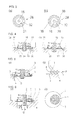
FIG. 1 shows an embodiment of a fluid control valve according to the present invention, in which (a) is a schematic sectional view and (b) is an enlarged view of a section A in (a); -
FIG. 2 is an enlarged view of an essential portion of the fluid control valve, for illustrating the effect of a concave portion of the valve shown inFIG. 1 ; -
FIG. 3(a) is a schematic bottom plan view of the valve, illustrating an annular convex portion shown inFIG. 1, and (b) shows a variation thereof; -
FIGS. 4(a), (b) are sectional views of essential portions of the fluid control valve just after the valve is opened, each showing other embodiments of the fluid control valve according to the present invention; -
FIGS. 5(a), (b) are a schematic sectional view and an enlarged view of an essential portion, respectively, illustrating a constricted portion of a conventional valve; and -
FIGS. 6(a), 6(b) are a schematic sectional view and an enlarged view of an essential portion, respectively, illustrating an axial offset G in the case of using a conventional valve. - In a fluid control valve, the pressure of the fluid is kept substantially uniform during opening and closing of the valve by providing a concave portion, a convex portion, etc., on one of the valve and the valve seat so as to minimize the length of a constricted portion of a fluid passage defined by the valve and the valve seat, thereby preventing valve flutter.
-
FIG. 1 through FIG. 3 show an embodiment of a fluid control valve according to the present invention. - In these drawings, that which is indicated as a whole by
reference numeral 10 is a thermostat device, which is a temperature-sensitive automatic valve, used, for example, in the cooling system of an automobile engine (not shown), mounted at the intersection between a radiator side liquid coolant passage and a bypass on the engine outlet side, used to control the temperature of the liquid coolant at the intake of the engine by selectively switching the flow of the coolant in the fluid passage defined by these passages. - The
thermostat device 10, as shown inFIG. 1(a) includes a thermo-element 11 that operates in response to changes in the temperature of a fluid. A substantially umbrella-shapedfirst valve 12 is fitted to one end (the top in the drawing) of the thermo-element 11, while a substantially flatsecond valve 13 is fitted to the tip of the valve stem (to be described below) extending toward the other end (the bottom in the drawing), At the center along the axis of the thermo-element 11 is provided acoil spring 14 as a biasing means that biases thefirst valve 12 toward the closed position, and aframe 15 that also serves to compress the spring is fitted thereto. Theframe 15 engages support stands on a valve housing that is a fixed part and which is described later in such as way as to continuously bias thefirst valve 12 toward the open position against thecoil spring 14, while at the same time is a member that slidably supports the thermo-element 11. - The thermo-
element 11 has a temperature-sensitive part that encloses a thermal expansion unit of wax or the like that senses the temperature of a fluid and expands or contracts accordingly. -
Reference numeral 20 in the drawing is a housing that forms the passage through which flows the liquid coolant that flows in from the radiator that is the fluid intake and outlet to the engine intake, and at the same time contains thethermostat device 10. Avalve chamber 21 that contains thethermostat device 10 is formed in the interior of thehousing 20, and defines afluid passage 25 constructed of aliquid coolant passage 21A from the radiator at the top of the drawing and aliquid coolant passage 21 B toward the engine at the right in the drawing. - A flange is provided at approximately the center in the long direction of the
thermostat device 10, inside which is formed avalve seat 22, opposite thefirst valve 12 and against which thefirst valve 12 can be seated. The thermo-element 11 and theframe 15 are assembled in a state in which thevalve 12 can be seated against thevalve seat 22. -
Reference numeral 23 in the drawing is an engagement part that engages the tip of thepiston rod 11 a. In the state shown inFIG. 1(a) , as thepiston rod 11 a protrudes upward due to the expansion of the thermal expansion unit, the thermo-element 11 and thefirst valve 12 move downward, thefirst valve 12 opens accordingly, and liquid coolant from the radiator is conducted into the engine. - At the same time, the
second valve 13 having a substantially flat shape is fitted to the bottom of therod 18 that is the valve shaft and which extends downward from the thermo-element 11 and is engaged by an E-ring or the like, and elastically supported by biasing by acoil spring 19. Thefluid passage 25, which is opened and closed by thesecond valve 13, opens at the bottom of thehousing 20, with the rim of theopening 25a forming avalve seat 26. - In the present embodiment, the structure is one in which the
second valve 13 is normally seated against theaforementioned valve seat 26, with thesecond valve 13 functioning as a relief valve that is opened in response to liquid coolant pressure on the bypass side. - In the
thermostat device 10 configured as described above, arelief valve 28 as a fluid control valve defined by thesecond valve 13 and thevalve seat 26 has the following configuration. - That is, according to the present invention, the
relief valve 28 is configured with thesecond valve 13 supported in a state in which it is biased by thecoil spring 19 against the tip of therod 18 that moves reciprocally back and forth in a direction orthogonal to thevalve seat 26, so as to minimize the length of a constricted portion of a fluid passage defined by thesecond valve 13 and thevalve seat 26 in thefluid control valve 28 that controls the flow of fluid in thefluid passage 25. - In particular, according to the present invention, as shown in
FIG. 1(b) ,FIG. 2 , andFIG. 3(a) , aconcave portion 31 is provided to broaden the area of the passage so as to widen the area that receives the pressure of the fluid, while leaving a minimum essential portion of thesecond valve 13 that is seated against thevalve seat 26. - Further, an annular
convex portion 32 is provided on that portion of thevalve 13 which is seated against thevalve seat 26 and which is continuous with theconcave portion 31 to minimize the length of a constricted portion of a fluid passage defined by the opening and closing of therelief valve 28. The annularconvex portion 32 is formed in the shape of a projecting hemisphere. - With a configuration such as this, in contrast to the conventional simple valve seating involving two flat planes, the length of the constricted portion is shortened and the negative pressure generated by the change in the speed of the flow of the coolant can be eliminated. In particular, with this configuration, the annular
convex portion 34 shapes the state of contact of thevalve 13 against thevalve seat 26 into a line, thereby obviously keeping the constricted portion to an absolute minimum. - Since the constricted portion of the fluid passage defined by the
valve 13 and thevalve seat 26 is kept to the essential minimum, the negative pressure generated by the change in the speed of the flow of the coolant is eliminated, thereby preventing valve flutter, that is, vibration and friction with and damage to surrounding parts such as the rod, piston, E-ring, etc., friction with and deformation of the housing, breakage of the coil spring, and noise caused by this vibration during opening and closing of the valve. - In addition, the pressure distribution during closing of the
valve 13 is such that, even when thevalve 13 and thevalve seat 26 are not coaxial but offset, the contact during seating can be maintained as a line contact, the area that receives the pressure of the fluid becomes uniform, and the valve can operate evenly without increasing the number of parts and without the valve tilting. Further, by eliminating the conventional valve flutter, the fluid control valve of the present embodiment prevents vibration and the friction with and damage to surrounding parts such as therod 18, piston, E-ring, etc., friction with and deformation of the housing, breakage of thecoil spring 19, and noise caused by this vibration. - In addition, since the fluid control valve of the present embodiment leaves a minimum essential portion of the
second valve 13 that is seated against thevalve seat 26 and forms aconcave portion 31 that broadens the area receiving the pressure of the fluid, as shown inFIG. 2 and elsewhere, thevalve 13 receives the pressure evenly without being affected by axial offset or the diameter of the bypass valve opening and can prevent vibration and the friction with and damage to surrounding parts such as the rod, piston, E-ring, etc., friction with and deformation of the housing, breakage of the coil spring, and noise caused by this vibration. - Further, gently sloping the above-described
concave portion 31 and the annular convex portion 32 (see part A inFIG. 2 ) has the same rectifying effect of smoothing the fluid flow as heretofore. In thethermostat valve 10, gently sloping the annularconvex portion 32 has the advantage of smoothing the flow of fluid to the temperature-sensitive portion of the thermostat. In addition, the above-describedconcave portion 31 can also be used as a spring seat for thecoil spring 19 that elastically supports thevalve 13. -
Patent Document 1 described above, although the drawings show a configuration providing a projection on the part of the valve that is seated against the valve seat that appears to be similar to the distinctive annularconvex portion 32 of the present invention, there is no suggestion whatsoever of such inPatent Document 1, nor is there any suggestion of minimizing the length of the passage at the closure between the valve and the valve seat. - It should be noted that, as shown in
FIG. 3(b) , multiple outwardly radiatinggrooves 38 may be formed in the above-described annularconvex portion 32 at predetermined intervals to form a passage that communicates between upstream and downstream sides of the valve. - With this sort of configuration, the
multiple grooves 38 formed in the annularconvex portion 32 allow the fluid to leak through even when the second valve (the flat valve) 13 is closed, thereby eliminating any fluctuation in temperature due to the sudden inflow of fluid when the valve is opened and thus improving temperature control and preventing hunting by thebypass valve 28. -
FIGS. 4(a), (b) show other embodiments of the present invention. - More specifically,
FIG. 4(a) shows a case in which an annularconvex portion 34 is formed as a hemispherical projecting portion formed on thevalve seat 26 against which thevalve 13 is seated. It can be easily understood that substantially the same effect as with the above-described embodiment can be obtained with this configuration as well. -
FIG. 4(b) shows a case in which an annularconvex portion 36 is formed on thevalve 13 as a bent, L-shaped portion along the rim of thevalve 13. It goes without saying that the same effect can be achieved with this configuration as well. - It should be noted that the present invention is not limited to the structure described in the embodiments described above, and accordingly, the shapes and structures of the parts that constitute the
thermostat device 10 and moreover the relief valve as thefluid control valve 28 may be modified and changed as convenient. - For example, it is also possible to adopt a thermostat device having a structure in which the
first valve 12 is installed closed and thesecond valve 13 open, thepiston 11 a projects upward in the drawing due to thermal expansion, the thermo-element 11 and the first andsecond valves FIG. 1(a) , and thefirst valve 12 opens and thesecond valve 1 closes. - In addition, although in the above-described embodiments the present invention is described with reference to an example using the
flat valve 13 as thefluid control valve 28, the present invention is not limited thereto and of course the valve may be any appropriate shape. In short, provided that the tip of the valve is elastically supported by a spring and there is a risk that flutter might occur, the valve may be of any shape or structure. - Further, although in the above-described embodiments the present invention is described with reference to an example of an annular
convex portion 32 formed on that portion of the substantially flatsecond valve 13 which is seated against thevalve seat 26, the present invention is not limited thereto and alternatively theconvex portion 32 may be triangular, rectangular, pentagonal, hexagonal, octagonal, star-shaped or otherwise multilateral in cross-section. - In addition, although in the above-described embodiments the
concave portion 31 and moreover theconvex portion 32 is formed on the portion of thevalve 13 that is seated against the valve seat so as to minimize the length of the constricted portion of the fluid passage defined by thesecond valve 13 and thevalve seat 26, the present invention is not limited thereto and alternatively a structure may be adopted in which thehousing 20 having thevalve seat 26 has a shape that reduces the area of the constricted portion, such as the teeth of a gear. - Although the above-described embodiments are described as applied to the
fluid control valve 28 installed as a relief valve in athermostat device 10, the present invention is not limited thereto and is applicable also to a valve device having the sole function of a relief valve. - Although the above-described embodiments describe an example in which the
thermostat device 10 is installed on the engine intake side in an engine cooling circuit, the present invention is not limited thereto and it goes without saying that the same effect can be obtained in a case in which thethermostat device 10 is installed on the engine outlet side. -
- 10
- Thermostat device
- 13
- Second valve (flat valve)
- 25
- Bypass fluid passage
- 25a
- Opening
- 26
- Valve seat
- 28
- Fluid control valve (relief valve)
- 31
- Concave portion
- 32, 34, 36
- Convex portion
Claims (6)
- A fluid control valve (28) characterized by having a valve (13) supported in a state in which it is biased by a spring (19) against a tip of a valve shaft (18) that moves reciprocally back and forth in a direction orthogonal to a valve seat (26),
configured so as to minimize the length of a constricted portion of a fluid passage (25) defined by the valve (13) and the valve seat (26). - The fluid control valve (28) as claimed in claim 1, characterized in that a concave portion (31) is formed on a part of the valve (13) that is seated against the valve seat (26) to widen an area that receives pressure of a flow of fluid through the fluid control valve (28).
- The fluid control valve (28) as claimed in claim 1 or claim 2, characterized in that an annular convex portion (32, 34, 36) to minimize the length of the constricted portion of the fluid passage (25) defined by the valve (13) and the valve seat (26) is provided on at least one of the valve (13) and the valve seat (26).
- The fluid control valve (28) as claimed in claim 1, claim 2, or claim 3, characterized in that the annular convex portion (32, 34, 36) is configured so that a state of contact between the valve (13) and the valve seat (26) is in the form of a line.
- The fluid control valve (28) as claimed in claim 3 or claim 4, characterized in that multiple outwardly radiating grooves (38) are formed in the annular convex portion (32, 34, 36) at predetermined intervals to form a passage that communicates between upstream and downstream sides of the valve (13).
- The fluid control valve (28) as claimed in claim 3, claim 4, or claim 5, characterized in that the annular convex portion (32, 34, 36) is configured as an L-shaped bent portion along a rim of the valve (13).
Applications Claiming Priority (2)
| Application Number | Priority Date | Filing Date | Title |
|---|---|---|---|
| JP2011288643A JP5912523B2 (en) | 2011-12-28 | 2011-12-28 | Fluid control valve |
| PCT/JP2012/075769 WO2013099386A1 (en) | 2011-12-28 | 2012-10-04 | Fluid control valve |
Publications (4)
| Publication Number | Publication Date |
|---|---|
| EP2799744A1 true EP2799744A1 (en) | 2014-11-05 |
| EP2799744A4 EP2799744A4 (en) | 2015-08-26 |
| EP2799744B1 EP2799744B1 (en) | 2020-12-09 |
| EP2799744B8 EP2799744B8 (en) | 2021-10-13 |
Family
ID=48696891
Family Applications (1)
| Application Number | Title | Priority Date | Filing Date |
|---|---|---|---|
| EP12862585.2A Active EP2799744B8 (en) | 2011-12-28 | 2012-10-04 | Fluid control valve |
Country Status (6)
| Country | Link |
|---|---|
| US (1) | US20140345711A1 (en) |
| EP (1) | EP2799744B8 (en) |
| JP (1) | JP5912523B2 (en) |
| KR (1) | KR102092946B1 (en) |
| CN (1) | CN104145146A (en) |
| WO (1) | WO2013099386A1 (en) |
Families Citing this family (13)
| Publication number | Priority date | Publication date | Assignee | Title |
|---|---|---|---|---|
| JP6274984B2 (en) * | 2014-06-25 | 2018-02-07 | 日本サーモスタット株式会社 | Thermostat valve |
| FR3024518B1 (en) * | 2014-07-29 | 2016-09-02 | Vernet | THERMOSTATIC SLEEVE VALVE |
| DE102014012688B4 (en) * | 2014-09-01 | 2022-04-21 | Acs Air Compressor Systeme Gmbh | multi-way valve |
| FR3034162B1 (en) * | 2015-03-24 | 2018-09-21 | Vernet | THERMOSTATIC DEVICE FOR CONTROLLING CIRCULATION OF A FLUID, AND THERMOSTATIC VALVE COMPRISING SUCH A DEVICE |
| US20160298763A1 (en) * | 2015-04-09 | 2016-10-13 | Bendix Commercial Vehicle Systems Llc | Piston assembly for an unloader valve of an air compressor |
| FR3044782B1 (en) | 2015-12-07 | 2018-01-12 | Vernet | THERMOSTATIC MONOCOMMANDE CARTRIDGE AND MIXER FAUCET WITH SUCH A CARTRIDGE |
| FR3050510B1 (en) | 2016-04-26 | 2018-09-21 | Vernet | MIXING UNIT AND MIXER TAP COMPRISING SUCH A MIXING UNIT |
| FR3050512B1 (en) | 2016-04-26 | 2018-09-28 | Vernet | MIXING UNIT AND MIXER TAP COMPRISING SUCH A MIXING UNIT |
| FR3054282B1 (en) | 2016-07-21 | 2018-08-31 | Vernet | MIXING UNIT AND MIXER TAP COMPRISING SUCH A MIXING UNIT |
| JP6867918B2 (en) * | 2017-09-08 | 2021-05-12 | 本田技研工業株式会社 | Check valve |
| KR20200073565A (en) * | 2018-12-14 | 2020-06-24 | 현대자동차주식회사 | Thermostat for an engine cooling system |
| JP7027367B2 (en) * | 2019-03-25 | 2022-03-01 | 株式会社鷺宮製作所 | Thermal expansion valve and refrigeration cycle system equipped with it |
| JP6947879B1 (en) * | 2020-06-09 | 2021-10-13 | 株式会社ソディック | Backflow prevention device for light metal injection equipment and backflow prevention method for light metal injection equipment |
Family Cites Families (28)
| Publication number | Priority date | Publication date | Assignee | Title |
|---|---|---|---|---|
| US1620524A (en) * | 1927-03-08 | of flint | ||
| US2643671A (en) * | 1952-06-21 | 1953-06-30 | Manning Maxwell & Moore Inc | Spring loaded pop-safety valve |
| JPS59101066U (en) * | 1982-12-27 | 1984-07-07 | 京三電機株式会社 | valve device |
| JPS62115576U (en) * | 1986-01-14 | 1987-07-22 | ||
| JPS62156684U (en) * | 1986-03-27 | 1987-10-05 | ||
| US4903939A (en) * | 1988-03-14 | 1990-02-27 | Fujikura Rubber, Ltd. | Pneumatically-operated valve |
| US5188150A (en) * | 1988-06-09 | 1993-02-23 | Esplin Trevor T | Valve assembly |
| JPH0341123A (en) | 1989-07-07 | 1991-02-21 | Agency Of Ind Science & Technol | Poly(disilene/ethylene) and its production |
| US5037277A (en) * | 1989-07-26 | 1991-08-06 | Flow International Corporation | Poppet valve for a high pressure fluid pump |
| JPH0746730Y2 (en) * | 1989-08-29 | 1995-10-25 | いすゞ自動車株式会社 | Engine cooling system |
| US5251871A (en) * | 1989-11-14 | 1993-10-12 | Isao Suzuki | Fluid flow control valve and valve disk |
| JPH0736213Y2 (en) * | 1992-02-28 | 1995-08-16 | 日信工業株式会社 | Check valve |
| JPH0622673U (en) * | 1992-08-27 | 1994-03-25 | エヌオーケー株式会社 | Valve device |
| JPH0810714Y2 (en) * | 1992-12-14 | 1996-03-29 | エヌテーシー工業株式会社 | Pressure relief valve for hot water supply facility |
| JP3401875B2 (en) * | 1993-10-29 | 2003-04-28 | 豊田合成株式会社 | Check valve |
| EP0716367B1 (en) * | 1994-12-09 | 2000-09-27 | NIPPON THERMOSTAT Co., Ltd. | Improved thermally controlled valve |
| SE523534C2 (en) * | 1998-03-10 | 2004-04-27 | Oehlins Racing Ab | Valve or pressure regulator device for effecting opening and / or closing functions or movements for two parts working against each other, eg cone / slide and seat / housing respectively. |
| JP2000250635A (en) * | 1999-02-26 | 2000-09-14 | Smc Corp | Regulator |
| DE19938249C2 (en) * | 1999-08-12 | 2002-03-07 | Stabilus Gmbh | Axially movable switching ring within a groove |
| JP2001248743A (en) * | 2000-03-02 | 2001-09-14 | Toyoda Gosei Co Ltd | Check valve |
| JP2004340275A (en) * | 2003-05-15 | 2004-12-02 | Kinjo Rubber Co Ltd | Valve body |
| JP4171900B2 (en) * | 2003-05-19 | 2008-10-29 | Smc株式会社 | Vacuum pressure control valve |
| DE102004008456B4 (en) * | 2004-02-13 | 2015-02-12 | Behr Thermot-Tronik Gmbh | Thermostatic valve, which forms a structural unit with a cover-like housing part |
| JP2006250239A (en) * | 2005-03-10 | 2006-09-21 | Kawasaki Precision Machinery Ltd | Seat block and valve device |
| JP4324946B2 (en) * | 2007-03-13 | 2009-09-02 | Smc株式会社 | Pilot type 3 port valve |
| US20080223316A1 (en) * | 2007-03-16 | 2008-09-18 | International Engine Intellectual Property Company, Llc | Engine thermostat having bypass pressure-dampening fluid passage |
| JP4945392B2 (en) * | 2007-09-20 | 2012-06-06 | 株式会社豊田自動織機 | Relief valve manufacturing method |
| DE102010034490B4 (en) * | 2010-08-17 | 2017-06-08 | BorgWarner Esslingen GmbH | Thermostatic valve for temperature control of an engine coolant |
-
2011
- 2011-12-28 JP JP2011288643A patent/JP5912523B2/en active Active
-
2012
- 2012-10-04 KR KR1020147018002A patent/KR102092946B1/en active Active
- 2012-10-04 EP EP12862585.2A patent/EP2799744B8/en active Active
- 2012-10-04 US US14/368,798 patent/US20140345711A1/en not_active Abandoned
- 2012-10-04 WO PCT/JP2012/075769 patent/WO2013099386A1/en not_active Ceased
- 2012-10-04 CN CN201280070081.1A patent/CN104145146A/en active Pending
Also Published As
| Publication number | Publication date |
|---|---|
| CN104145146A (en) | 2014-11-12 |
| EP2799744B8 (en) | 2021-10-13 |
| JP5912523B2 (en) | 2016-04-27 |
| KR102092946B1 (en) | 2020-03-25 |
| JP2013137070A (en) | 2013-07-11 |
| EP2799744B1 (en) | 2020-12-09 |
| WO2013099386A1 (en) | 2013-07-04 |
| KR20140107341A (en) | 2014-09-04 |
| EP2799744A4 (en) | 2015-08-26 |
| US20140345711A1 (en) | 2014-11-27 |
Similar Documents
| Publication | Publication Date | Title |
|---|---|---|
| EP2799744B1 (en) | Fluid control valve | |
| US10443482B2 (en) | Thermostat valve with temperature responsive thermo-element | |
| US9133952B2 (en) | Thermostatic bypass valve with a unique valve seat | |
| US8893979B2 (en) | Thermostat device | |
| JP5680601B2 (en) | Piston cooling jet | |
| US20150240795A1 (en) | Control valve for variable displacement compressor | |
| US20060163373A1 (en) | Thermostat device | |
| US20090183696A1 (en) | Liquid cooling system for internal combustion engine | |
| KR101733466B1 (en) | Bypass valve and bypass valve assembly having the same | |
| KR102463203B1 (en) | Coolant control valve unit, and cooling system having this | |
| US5549244A (en) | Thermally controlled valve for internal combustion engines | |
| KR102463202B1 (en) | Coolant control valve unit, and cooling system having this | |
| WO2024247512A1 (en) | Thermostat device | |
| JP2017186927A (en) | Temperature-sensitive valve mechanism and method of using the same | |
| JP2014070609A (en) | Piston cooling jet | |
| JP5574180B2 (en) | Fluid control valve | |
| JP6954101B2 (en) | Cooling device for additive injection valve | |
| JP2014070605A (en) | Piston cooling jet | |
| US5515815A (en) | Self-flushing thermostat | |
| JP2014070607A (en) | Piston cooling jet | |
| JP2014145341A (en) | Thermostat device | |
| US2353546A (en) | Oil cooler controlling structure | |
| US2165136A (en) | Temperature regulator | |
| JP5618141B2 (en) | Fluid control valve | |
| US20070290059A1 (en) | Flow control thermostat for internal combustion engines and method of using same |
Legal Events
| Date | Code | Title | Description |
|---|---|---|---|
| PUAI | Public reference made under article 153(3) epc to a published international application that has entered the european phase |
Free format text: ORIGINAL CODE: 0009012 |
|
| 17P | Request for examination filed |
Effective date: 20140625 |
|
| AK | Designated contracting states |
Kind code of ref document: A1 Designated state(s): AL AT BE BG CH CY CZ DE DK EE ES FI FR GB GR HR HU IE IS IT LI LT LU LV MC MK MT NL NO PL PT RO RS SE SI SK SM TR |
|
| DAX | Request for extension of the european patent (deleted) | ||
| RA4 | Supplementary search report drawn up and despatched (corrected) |
Effective date: 20150727 |
|
| RIC1 | Information provided on ipc code assigned before grant |
Ipc: F16K 17/04 20060101ALI20150721BHEP Ipc: F16K 1/36 20060101AFI20150721BHEP Ipc: F16K 1/42 20060101ALI20150721BHEP Ipc: F16K 31/68 20060101ALI20150721BHEP Ipc: F01P 7/16 20060101ALI20150721BHEP |
|
| STAA | Information on the status of an ep patent application or granted ep patent |
Free format text: STATUS: EXAMINATION IS IN PROGRESS |
|
| 17Q | First examination report despatched |
Effective date: 20180628 |
|
| GRAP | Despatch of communication of intention to grant a patent |
Free format text: ORIGINAL CODE: EPIDOSNIGR1 |
|
| STAA | Information on the status of an ep patent application or granted ep patent |
Free format text: STATUS: GRANT OF PATENT IS INTENDED |
|
| INTG | Intention to grant announced |
Effective date: 20200603 |
|
| GRAS | Grant fee paid |
Free format text: ORIGINAL CODE: EPIDOSNIGR3 |
|
| GRAA | (expected) grant |
Free format text: ORIGINAL CODE: 0009210 |
|
| STAA | Information on the status of an ep patent application or granted ep patent |
Free format text: STATUS: THE PATENT HAS BEEN GRANTED |
|
| AK | Designated contracting states |
Kind code of ref document: B1 Designated state(s): AL AT BE BG CH CY CZ DE DK EE ES FI FR GB GR HR HU IE IS IT LI LT LU LV MC MK MT NL NO PL PT RO RS SE SI SK SM TR |
|
| REG | Reference to a national code |
Ref country code: GB Ref legal event code: FG4D |
|
| REG | Reference to a national code |
Ref country code: AT Ref legal event code: REF Ref document number: 1343790 Country of ref document: AT Kind code of ref document: T Effective date: 20201215 Ref country code: CH Ref legal event code: EP |
|
| REG | Reference to a national code |
Ref country code: DE Ref legal event code: R096 Ref document number: 602012073689 Country of ref document: DE |
|
| REG | Reference to a national code |
Ref country code: IE Ref legal event code: FG4D |
|
| PG25 | Lapsed in a contracting state [announced via postgrant information from national office to epo] |
Ref country code: FI Free format text: LAPSE BECAUSE OF FAILURE TO SUBMIT A TRANSLATION OF THE DESCRIPTION OR TO PAY THE FEE WITHIN THE PRESCRIBED TIME-LIMIT Effective date: 20201209 Ref country code: RS Free format text: LAPSE BECAUSE OF FAILURE TO SUBMIT A TRANSLATION OF THE DESCRIPTION OR TO PAY THE FEE WITHIN THE PRESCRIBED TIME-LIMIT Effective date: 20201209 Ref country code: NO Free format text: LAPSE BECAUSE OF FAILURE TO SUBMIT A TRANSLATION OF THE DESCRIPTION OR TO PAY THE FEE WITHIN THE PRESCRIBED TIME-LIMIT Effective date: 20210309 Ref country code: GR Free format text: LAPSE BECAUSE OF FAILURE TO SUBMIT A TRANSLATION OF THE DESCRIPTION OR TO PAY THE FEE WITHIN THE PRESCRIBED TIME-LIMIT Effective date: 20210310 |
|
| REG | Reference to a national code |
Ref country code: AT Ref legal event code: MK05 Ref document number: 1343790 Country of ref document: AT Kind code of ref document: T Effective date: 20201209 |
|
| PG25 | Lapsed in a contracting state [announced via postgrant information from national office to epo] |
Ref country code: BG Free format text: LAPSE BECAUSE OF FAILURE TO SUBMIT A TRANSLATION OF THE DESCRIPTION OR TO PAY THE FEE WITHIN THE PRESCRIBED TIME-LIMIT Effective date: 20210309 Ref country code: LV Free format text: LAPSE BECAUSE OF FAILURE TO SUBMIT A TRANSLATION OF THE DESCRIPTION OR TO PAY THE FEE WITHIN THE PRESCRIBED TIME-LIMIT Effective date: 20201209 Ref country code: SE Free format text: LAPSE BECAUSE OF FAILURE TO SUBMIT A TRANSLATION OF THE DESCRIPTION OR TO PAY THE FEE WITHIN THE PRESCRIBED TIME-LIMIT Effective date: 20201209 |
|
| REG | Reference to a national code |
Ref country code: NL Ref legal event code: MP Effective date: 20201209 |
|
| PG25 | Lapsed in a contracting state [announced via postgrant information from national office to epo] |
Ref country code: HR Free format text: LAPSE BECAUSE OF FAILURE TO SUBMIT A TRANSLATION OF THE DESCRIPTION OR TO PAY THE FEE WITHIN THE PRESCRIBED TIME-LIMIT Effective date: 20201209 Ref country code: NL Free format text: LAPSE BECAUSE OF FAILURE TO SUBMIT A TRANSLATION OF THE DESCRIPTION OR TO PAY THE FEE WITHIN THE PRESCRIBED TIME-LIMIT Effective date: 20201209 |
|
| REG | Reference to a national code |
Ref country code: LT Ref legal event code: MG9D |
|
| PG25 | Lapsed in a contracting state [announced via postgrant information from national office to epo] |
Ref country code: PT Free format text: LAPSE BECAUSE OF FAILURE TO SUBMIT A TRANSLATION OF THE DESCRIPTION OR TO PAY THE FEE WITHIN THE PRESCRIBED TIME-LIMIT Effective date: 20210409 Ref country code: RO Free format text: LAPSE BECAUSE OF FAILURE TO SUBMIT A TRANSLATION OF THE DESCRIPTION OR TO PAY THE FEE WITHIN THE PRESCRIBED TIME-LIMIT Effective date: 20201209 Ref country code: SK Free format text: LAPSE BECAUSE OF FAILURE TO SUBMIT A TRANSLATION OF THE DESCRIPTION OR TO PAY THE FEE WITHIN THE PRESCRIBED TIME-LIMIT Effective date: 20201209 Ref country code: LT Free format text: LAPSE BECAUSE OF FAILURE TO SUBMIT A TRANSLATION OF THE DESCRIPTION OR TO PAY THE FEE WITHIN THE PRESCRIBED TIME-LIMIT Effective date: 20201209 Ref country code: SM Free format text: LAPSE BECAUSE OF FAILURE TO SUBMIT A TRANSLATION OF THE DESCRIPTION OR TO PAY THE FEE WITHIN THE PRESCRIBED TIME-LIMIT Effective date: 20201209 Ref country code: EE Free format text: LAPSE BECAUSE OF FAILURE TO SUBMIT A TRANSLATION OF THE DESCRIPTION OR TO PAY THE FEE WITHIN THE PRESCRIBED TIME-LIMIT Effective date: 20201209 |
|
| PG25 | Lapsed in a contracting state [announced via postgrant information from national office to epo] |
Ref country code: AT Free format text: LAPSE BECAUSE OF FAILURE TO SUBMIT A TRANSLATION OF THE DESCRIPTION OR TO PAY THE FEE WITHIN THE PRESCRIBED TIME-LIMIT Effective date: 20201209 Ref country code: PL Free format text: LAPSE BECAUSE OF FAILURE TO SUBMIT A TRANSLATION OF THE DESCRIPTION OR TO PAY THE FEE WITHIN THE PRESCRIBED TIME-LIMIT Effective date: 20201209 |
|
| GRAT | Correction requested after decision to grant or after decision to maintain patent in amended form |
Free format text: ORIGINAL CODE: EPIDOSNCDEC |
|
| REG | Reference to a national code |
Ref country code: DE Ref legal event code: R097 Ref document number: 602012073689 Country of ref document: DE |
|
| REG | Reference to a national code |
Ref country code: CH Ref legal event code: PK Free format text: BERICHTIGUNGEN Ref country code: CH Ref legal event code: PK Free format text: BERICHTIGUNG B8 |
|
| PG25 | Lapsed in a contracting state [announced via postgrant information from national office to epo] |
Ref country code: IS Free format text: LAPSE BECAUSE OF FAILURE TO SUBMIT A TRANSLATION OF THE DESCRIPTION OR TO PAY THE FEE WITHIN THE PRESCRIBED TIME-LIMIT Effective date: 20210409 |
|
| RIN2 | Information on inventor provided after grant (corrected) |
Inventor name: NISHINO, YOSHINORI Inventor name: ONUMA, KEIKI Inventor name: UENO, SHOZO |
|
| PLBE | No opposition filed within time limit |
Free format text: ORIGINAL CODE: 0009261 |
|
| STAA | Information on the status of an ep patent application or granted ep patent |
Free format text: STATUS: NO OPPOSITION FILED WITHIN TIME LIMIT |
|
| PG25 | Lapsed in a contracting state [announced via postgrant information from national office to epo] |
Ref country code: AL Free format text: LAPSE BECAUSE OF FAILURE TO SUBMIT A TRANSLATION OF THE DESCRIPTION OR TO PAY THE FEE WITHIN THE PRESCRIBED TIME-LIMIT Effective date: 20201209 |
|
| 26N | No opposition filed |
Effective date: 20210910 |
|
| PG25 | Lapsed in a contracting state [announced via postgrant information from national office to epo] |
Ref country code: SI Free format text: LAPSE BECAUSE OF FAILURE TO SUBMIT A TRANSLATION OF THE DESCRIPTION OR TO PAY THE FEE WITHIN THE PRESCRIBED TIME-LIMIT Effective date: 20201209 Ref country code: DK Free format text: LAPSE BECAUSE OF FAILURE TO SUBMIT A TRANSLATION OF THE DESCRIPTION OR TO PAY THE FEE WITHIN THE PRESCRIBED TIME-LIMIT Effective date: 20201209 Ref country code: ES Free format text: LAPSE BECAUSE OF FAILURE TO SUBMIT A TRANSLATION OF THE DESCRIPTION OR TO PAY THE FEE WITHIN THE PRESCRIBED TIME-LIMIT Effective date: 20201209 |
|
| REG | Reference to a national code |
Ref country code: CH Ref legal event code: PL |
|
| PG25 | Lapsed in a contracting state [announced via postgrant information from national office to epo] |
Ref country code: IS Free format text: LAPSE BECAUSE OF FAILURE TO SUBMIT A TRANSLATION OF THE DESCRIPTION OR TO PAY THE FEE WITHIN THE PRESCRIBED TIME-LIMIT Effective date: 20210409 |
|
| REG | Reference to a national code |
Ref country code: BE Ref legal event code: MM Effective date: 20211031 |
|
| PG25 | Lapsed in a contracting state [announced via postgrant information from national office to epo] |
Ref country code: MC Free format text: LAPSE BECAUSE OF FAILURE TO SUBMIT A TRANSLATION OF THE DESCRIPTION OR TO PAY THE FEE WITHIN THE PRESCRIBED TIME-LIMIT Effective date: 20201209 |
|
| PG25 | Lapsed in a contracting state [announced via postgrant information from national office to epo] |
Ref country code: LU Free format text: LAPSE BECAUSE OF NON-PAYMENT OF DUE FEES Effective date: 20211004 Ref country code: BE Free format text: LAPSE BECAUSE OF NON-PAYMENT OF DUE FEES Effective date: 20211031 |
|
| PG25 | Lapsed in a contracting state [announced via postgrant information from national office to epo] |
Ref country code: LI Free format text: LAPSE BECAUSE OF NON-PAYMENT OF DUE FEES Effective date: 20211031 Ref country code: CH Free format text: LAPSE BECAUSE OF NON-PAYMENT OF DUE FEES Effective date: 20211031 |
|
| PG25 | Lapsed in a contracting state [announced via postgrant information from national office to epo] |
Ref country code: IE Free format text: LAPSE BECAUSE OF NON-PAYMENT OF DUE FEES Effective date: 20211004 |
|
| PG25 | Lapsed in a contracting state [announced via postgrant information from national office to epo] |
Ref country code: HU Free format text: LAPSE BECAUSE OF FAILURE TO SUBMIT A TRANSLATION OF THE DESCRIPTION OR TO PAY THE FEE WITHIN THE PRESCRIBED TIME-LIMIT; INVALID AB INITIO Effective date: 20121004 Ref country code: CY Free format text: LAPSE BECAUSE OF FAILURE TO SUBMIT A TRANSLATION OF THE DESCRIPTION OR TO PAY THE FEE WITHIN THE PRESCRIBED TIME-LIMIT Effective date: 20201209 |
|
| P01 | Opt-out of the competence of the unified patent court (upc) registered |
Effective date: 20230420 |
|
| PG25 | Lapsed in a contracting state [announced via postgrant information from national office to epo] |
Ref country code: MK Free format text: LAPSE BECAUSE OF FAILURE TO SUBMIT A TRANSLATION OF THE DESCRIPTION OR TO PAY THE FEE WITHIN THE PRESCRIBED TIME-LIMIT Effective date: 20201209 |
|
| PG25 | Lapsed in a contracting state [announced via postgrant information from national office to epo] |
Ref country code: MT Free format text: LAPSE BECAUSE OF FAILURE TO SUBMIT A TRANSLATION OF THE DESCRIPTION OR TO PAY THE FEE WITHIN THE PRESCRIBED TIME-LIMIT Effective date: 20201209 |
|
| PGFP | Annual fee paid to national office [announced via postgrant information from national office to epo] |
Ref country code: IT Payment date: 20250922 Year of fee payment: 14 |
|
| PGFP | Annual fee paid to national office [announced via postgrant information from national office to epo] |
Ref country code: GB Payment date: 20250828 Year of fee payment: 14 |
|
| PGFP | Annual fee paid to national office [announced via postgrant information from national office to epo] |
Ref country code: FR Payment date: 20250908 Year of fee payment: 14 |
|
| PGFP | Annual fee paid to national office [announced via postgrant information from national office to epo] |
Ref country code: CZ Payment date: 20250923 Year of fee payment: 14 |
|
| PG25 | Lapsed in a contracting state [announced via postgrant information from national office to epo] |
Ref country code: TR Free format text: LAPSE BECAUSE OF FAILURE TO SUBMIT A TRANSLATION OF THE DESCRIPTION OR TO PAY THE FEE WITHIN THE PRESCRIBED TIME-LIMIT Effective date: 20201209 |
|
| PGFP | Annual fee paid to national office [announced via postgrant information from national office to epo] |
Ref country code: DE Payment date: 20250902 Year of fee payment: 14 |