EP2799721A1 - Axial turbomachine stator guide with ailerons on the vane feet - Google Patents
Axial turbomachine stator guide with ailerons on the vane feet Download PDFInfo
- Publication number
- EP2799721A1 EP2799721A1 EP20130166527 EP13166527A EP2799721A1 EP 2799721 A1 EP2799721 A1 EP 2799721A1 EP 20130166527 EP20130166527 EP 20130166527 EP 13166527 A EP13166527 A EP 13166527A EP 2799721 A1 EP2799721 A1 EP 2799721A1
- Authority
- EP
- European Patent Office
- Prior art keywords
- main
- blades
- auxiliary
- vanes
- blade
- Prior art date
- Legal status (The legal status is an assumption and is not a legal conclusion. Google has not performed a legal analysis and makes no representation as to the accuracy of the status listed.)
- Granted
Links
Images
Classifications
-
- F—MECHANICAL ENGINEERING; LIGHTING; HEATING; WEAPONS; BLASTING
- F01—MACHINES OR ENGINES IN GENERAL; ENGINE PLANTS IN GENERAL; STEAM ENGINES
- F01D—NON-POSITIVE DISPLACEMENT MACHINES OR ENGINES, e.g. STEAM TURBINES
- F01D5/00—Blades; Blade-carrying members; Heating, heat-insulating, cooling or antivibration means on the blades or the members
- F01D5/12—Blades
- F01D5/14—Form or construction
- F01D5/141—Shape, i.e. outer, aerodynamic form
- F01D5/142—Shape, i.e. outer, aerodynamic form of the blades of successive rotor or stator blade-rows
-
- F—MECHANICAL ENGINEERING; LIGHTING; HEATING; WEAPONS; BLASTING
- F04—POSITIVE - DISPLACEMENT MACHINES FOR LIQUIDS; PUMPS FOR LIQUIDS OR ELASTIC FLUIDS
- F04D—NON-POSITIVE-DISPLACEMENT PUMPS
- F04D29/00—Details, component parts, or accessories
- F04D29/40—Casings; Connections of working fluid
- F04D29/52—Casings; Connections of working fluid for axial pumps
- F04D29/54—Fluid-guiding means, e.g. diffusers
- F04D29/541—Specially adapted for elastic fluid pumps
- F04D29/542—Bladed diffusers
- F04D29/544—Blade shapes
-
- F—MECHANICAL ENGINEERING; LIGHTING; HEATING; WEAPONS; BLASTING
- F01—MACHINES OR ENGINES IN GENERAL; ENGINE PLANTS IN GENERAL; STEAM ENGINES
- F01D—NON-POSITIVE DISPLACEMENT MACHINES OR ENGINES, e.g. STEAM TURBINES
- F01D5/00—Blades; Blade-carrying members; Heating, heat-insulating, cooling or antivibration means on the blades or the members
- F01D5/12—Blades
- F01D5/14—Form or construction
- F01D5/141—Shape, i.e. outer, aerodynamic form
- F01D5/146—Shape, i.e. outer, aerodynamic form of blades with tandem configuration, split blades or slotted blades
-
- F—MECHANICAL ENGINEERING; LIGHTING; HEATING; WEAPONS; BLASTING
- F01—MACHINES OR ENGINES IN GENERAL; ENGINE PLANTS IN GENERAL; STEAM ENGINES
- F01D—NON-POSITIVE DISPLACEMENT MACHINES OR ENGINES, e.g. STEAM TURBINES
- F01D9/00—Stators
- F01D9/02—Nozzles; Nozzle boxes; Stator blades; Guide conduits, e.g. individual nozzles
- F01D9/04—Nozzles; Nozzle boxes; Stator blades; Guide conduits, e.g. individual nozzles forming ring or sector
- F01D9/041—Nozzles; Nozzle boxes; Stator blades; Guide conduits, e.g. individual nozzles forming ring or sector using blades
-
- F—MECHANICAL ENGINEERING; LIGHTING; HEATING; WEAPONS; BLASTING
- F04—POSITIVE - DISPLACEMENT MACHINES FOR LIQUIDS; PUMPS FOR LIQUIDS OR ELASTIC FLUIDS
- F04D—NON-POSITIVE-DISPLACEMENT PUMPS
- F04D29/00—Details, component parts, or accessories
- F04D29/40—Casings; Connections of working fluid
- F04D29/52—Casings; Connections of working fluid for axial pumps
- F04D29/54—Fluid-guiding means, e.g. diffusers
- F04D29/541—Specially adapted for elastic fluid pumps
- F04D29/542—Bladed diffusers
-
- F—MECHANICAL ENGINEERING; LIGHTING; HEATING; WEAPONS; BLASTING
- F04—POSITIVE - DISPLACEMENT MACHINES FOR LIQUIDS; PUMPS FOR LIQUIDS OR ELASTIC FLUIDS
- F04D—NON-POSITIVE-DISPLACEMENT PUMPS
- F04D29/00—Details, component parts, or accessories
- F04D29/66—Combating cavitation, whirls, noise, vibration or the like; Balancing
- F04D29/68—Combating cavitation, whirls, noise, vibration or the like; Balancing by influencing boundary layers
- F04D29/681—Combating cavitation, whirls, noise, vibration or the like; Balancing by influencing boundary layers especially adapted for elastic fluid pumps
-
- Y—GENERAL TAGGING OF NEW TECHNOLOGICAL DEVELOPMENTS; GENERAL TAGGING OF CROSS-SECTIONAL TECHNOLOGIES SPANNING OVER SEVERAL SECTIONS OF THE IPC; TECHNICAL SUBJECTS COVERED BY FORMER USPC CROSS-REFERENCE ART COLLECTIONS [XRACs] AND DIGESTS
- Y02—TECHNOLOGIES OR APPLICATIONS FOR MITIGATION OR ADAPTATION AGAINST CLIMATE CHANGE
- Y02T—CLIMATE CHANGE MITIGATION TECHNOLOGIES RELATED TO TRANSPORTATION
- Y02T50/00—Aeronautics or air transport
- Y02T50/60—Efficient propulsion technologies, e.g. for aircraft
Definitions
- the invention relates to an axial compressor rectifier. More particularly, the invention relates to a turbomachine rectifier comprising main blades and auxiliary blades associated with the main blades. The invention also relates to an axial turbomachine provided with a rectifier according to the invention.
- the axial turbomachines In order to straighten their annular flows, the axial turbomachines have rectifiers. These blade grids are disposed downstream of each annular row of rotor blades. They deviate an annular flow so as to transform its tangential component into an axial component. This flow becomes able to be accelerated again by another annular row of rotor blades placed downstream.
- a rectifier generally has an inner ferrule and an outer ferrule between which the stator blades radially extend.
- the annular flow can be detached from the blades, creating the passage of the entropy that reduces the efficiency of the turbomachine.
- the document FR 2 939 852 A1 discloses a bladed stator with intermediate blades. These can be carried by an inner shell or an outer shell. Their dimensions are smaller than those of the stator vanes and they are arranged in the downstream portion of the rectifier, set back with respect to the main vanes.
- This rectifier architecture is intended to reduce the detachments at the ferrule. However, detachments can still occur on the upper surface of the blades. They cause eddies that further reduce the efficiency of the turbomachine.
- the document EP 1927 723 B1 discloses an axial compressor stator stage of a turbomachine.
- a series of slats is arranged on the extrados side of each blade.
- the slats reduce secondary flows between the blades. However, they are arranged axially at the blades.
- a detachment can however be observed on the surface extrados of the dawn, with the approach of its trailing edge. This detachment generates entropy which reduces the efficiency of the turbomachine.
- the presence of a plurality of lamellae reduces the passage section in the annular vein, which creates pressure losses.
- the invention aims to solve at least one of the problems raised by the prior art. More specifically, the invention aims to improve the ability of a rectifier to straighten a flow. More specifically, the object of the invention is to be able to increase the outlet pressure of a bladed rectifier. The invention also aims to improve the efficiency of a compressor with a bladed rectifier.
- the invention relates to an axial axial turbomachine rectifier, comprising: an annular row of radially extending main stator vanes, each of said vanes comprising a pressure face and a vacuum face; a series of auxiliary stator vanes disposed between the main vanes; remarkable in that each of the auxiliary vanes is associated with one of the main vanes extending along and downstream from the pressure face of the associated main vane, at a distance, in a circumferential direction, which is less than 30 % of the distance between two neighboring main blades.
- the auxiliary blades extend substantially parallel to their associated main blades, respectively.
- the auxiliary blades axially overlap the main blades associated over a distance C of between 5% and 50%, preferably between 10% and 30%, of their axial length.
- the axial overlap between the auxiliary blades and the associated main blades is limited to the distance C.
- the portion of the auxiliary blades extending from their leading edge on 30% of the rope is at a height, in an axial direction, the trailing edge of the respective associated main blades.
- the length of the rope of the auxiliary blades is less, preferably 50%, more preferably 40%, more preferably 30%, than that of the associated main blades.
- the rope of each of the auxiliary blades forms an angle ⁇ with the rope of the respective associated main blades which is between 5 ° and 45 °, preferably between 5 ° and 20 °.
- the auxiliary blades are configured and positioned to generate, during operation of the turbomachine, a vacuum at the trailing edge of the associated main blades, said vacuum deviating a part of the circulating flow of the side of the negative side of the associated main blades towards said trailing edge.
- each of the auxiliary blades comprises a pressure face and a vacuum face, the latter being opposite the pressure face of the associated main blade, the vacuum face of the auxiliary blade generating a depression at the trailing edge of the associated main blade.
- the rope of the auxiliary blades forms an angle with the tangent of the pressure face of the blades main associated with the trailing edge is less than 20 °, preferably 15 °, more preferably 10 °.
- the auxiliary blades axially overlap the main blades associated over a distance C of between 5% and 50%, preferably between 10% and 30%, of their axial length.
- the auxiliary blades have a radial height of between 10% and 100%, preferably between 10% and 50%, more preferably between 15% and 25%, of the radial height of the associated main blades.
- each main blade comprises a first portion and a second portion arranged radially relative to each other, at the level of the second portion, the pressure face is more axially curved than at the first portion, each auxiliary blade extending radially substantially along 80% to 120%, preferably 90% to 110%, of the radial height of the second portion of the associated main blade.
- each auxiliary blade has a radial height of between 80% and 120%, preferably between 90% and 110%, of the radial height of the second portion of the associated main blade.
- the rectifier comprises an outer annular wall and preferably an inner annular wall coaxial with the outer annular wall, the main vanes extending radially from the outer annular wall, the auxiliary vanes extending radially from the outer annular wall and / or from the inner annular wall.
- the auxiliary blades and the annular wall or one of the annular walls from which said blades extend are made of material, preferably of composite material or metal material.
- only one auxiliary blade is associated with each of the main blades.
- only one auxiliary blade is present between two adjacent main blades.
- the invention also relates to a turbomachine comprising a compressor and / or a turbine with at least one rectifier, characterized in that the or at least one of the rectifiers is in accordance with the invention.
- the surface of each main blade is greater than the surface of the auxiliary blade.
- the annular row of main blades comprises at least one main blade different and / or differently arranged relative to the other main blades of the row.
- the invention makes it possible to reduce and / or delay the stall of a flow bypassing a main blade on the side of its depression face.
- the stall can be removed.
- the invention thus increases the support provided by the blades within a rectifier and the ability of the latter to straighten a flow is improved.
- Auxiliary blades contribute indirectly to the recovery of the flow. It contributes to a main dawn by sucking a part of the flow that bypasses the latter by the face of depression. It also contributes in a direct way thanks to its geometry and its own surface which extends in the flow.
- the invention makes it possible to improve the efficiency of a compressor or a turbine provided with such rectifiers.
- a turbomachine equipped with such a compressor and / or such a turbine will have a better efficiency.
- the figure 1 represents an axial turbomachine according to the invention.
- the figure 2 is a sectional view of a turbomachine compressor according to the invention.
- the figure 3 is an elevation view of one of the compressor's rectifiers of the figure 1 according to the invention.
- the figure 4 has a main blade and an auxiliary stator blade according to the invention.
- the figure 5 represents a rectifier according to the invention whose blades are seen tangentially to the annular shape of the rectifier.
- inner or inner and outer or outer refer to a positioning relative to the axis of rotation of an axial turbomachine.
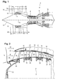
- the figure 1 represents in simplified manner an axial turbomachine. It is in this case a double-flow turbojet engine.
- the turbojet engine 2 comprises a first compression level, called a low-pressure compressor 4, a second compression level, called a high-pressure compressor 6, a combustion chamber 8 and one or more levels of turbines 10.
- the mechanical power the turbine 10 transmitted via the central shaft to the rotor 12 sets in motion the two compressors 4 and 6.
- Reducing means can increase the speed of rotation transmitted to the compressors.
- the different turbine stages can each be connected to the compressor stages via concentric shafts.
- the latter comprise several rows of rotor blades associated with rows of stator vanes. The rotation of the rotor about its axis of rotation 14 thus makes it possible to generate an air flow and to compress it progressively until it reaches the combustion chamber 10.
- a commonly designated fan inlet fan 16 is coupled to the rotor 12 and generates a flow of air which is divided into a primary flow 18 passing through the various levels mentioned above of the turbomachine, and a secondary flow 20 passing through an annular duct (partially represented) along the machine to then join the primary flow at the turbine outlet.
- the primary 18 and secondary 20 streams are annular flows, they are channeled by the casing of the turbomachine.
- the casing has cylindrical walls or inner and outer ferrules.
- the figure 2 is a sectional view of a low-pressure compressor 4 of an axial turbomachine 2 such as that of the figure 1 . There can be observed a portion of the fan 16 and the separation nozzle 22 of the primary flow 18 and the secondary flow 20.
- the rotor 12 comprises several, in this case three rows of rotor blades 24.
- the low pressure compressor 4 comprises several rectifiers, in this case four, each containing a row of stator vanes 26.
- the rectifiers are associated with the fan 16 or a row of rotor vanes to straighten the flow of air, so as to convert the speed of the flow into pressure.
- Each meeting of a rectifier and a row of rotor blades forms a compression stage.
- a rectifier comprises at least one annular wall, preferably two annular walls, which are capable of guiding the primary annular flow 18.
- the annular walls may be an inner shell 28 or an outer shell 30.
- At least one of the rectifiers may comprise one, preferably several layers of abradable material 32.
- the compressor comprises layers of abradable material 32 under each inner shell 28 and on the casing 30 at the ends of the outer ends of each row of rotor blades 24.
- stator vanes 26 extend substantially radially from the outer casing 30 to their associated inner ferrule 28. This is attached to the inner end of the stator vanes 26.
- the latter are regularly spaced from each other, and have the same angular orientation in the flow.
- these vanes are identical.
- the spacing between the stator vanes may vary locally as well as their angular orientation. Some stator vanes may be different from the rest of the vanes in the row.
- the stator vanes 26 are main stator vanes 26. At least one of the rectifiers is provided with at least one stator blade auxiliary 34, which is disposed downstream of one of its main blades 26. Preferably, each main blade 26 of the same rectifier is provided with an auxiliary blade 34.
- the set of auxiliary blades 34 of a rectifier forms an annular row of blades. Preferably, all the rectifiers are provided with auxiliary blades 34.
- the auxiliary blades 34 extend radially from an annular wall (28, 30).
- One main blade 26 may be provided with two auxiliary blades 34.
- the ends of these two auxiliary blades 34 are spaced apart from each other. the other.
- all the blades of the same rectifier are provided with two auxiliary blades 34.
- An inner shell 28 and its auxiliary blades 34 may be integral.
- An outer housing portion 30 and auxiliary blades 34 may be integral.
- the outer casing 30 may be formed of several outer rings each belonging to a rectifier.
- a rectifier can be segmented.
- a rectifier or a rectifier segment may have come from matter.
- a rectifier or a rectifier segment can be made of composite materials and be injected, or be made of metallic materials and be machined by electroerosion.
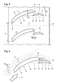
- the figure 3 is an elevational view of a portion of a compressor rectifier of the figure 2 .
- the rectifier comprises main blades 26 and auxiliary blades 34 which are each associated with a main blade 26.
- the main blades 26 each have a leading edge 36 and a trailing edge 38. They each have a face 40 intended to work. in pressure and a face 42 for working in depression. These faces extend from the leading edge 36 to the trailing edge 38 of the blade.
- the main blades can be arched locally or over their entire height.
- the ropes 44 of the main blades 26 are usually inclined relative to the axis 14 of rotation of the turbomachine.
- the auxiliary blades 34 are arranged axially at the level of the trailing edges 38 of the main vanes 26 between said vanes. Each of the auxiliary blades 34 is associated with a main blade 26 while being arranged in the vicinity of the trailing edge 38 of said blade.
- the auxiliary blades 34 each have a leading edge 46 and a trailing edge 48. They each comprise a face intended to work in pressure 50 and a face intended to work in depression 52. These faces extend from one edge to the other. attack 46 at a trailing edge 48 of dawn.
- the depression face 52 of an auxiliary blade 34 is opposite the pressure face 40 of the associated main blade 26.
- the spacing between the main blades 26 is greater than twice the distance between a main blade 26 and an associated auxiliary blade 34.
- the distance D1 between the leading edges 36 of the main blades 26 is greater than twice the tangential distance D2 between the trailing edge 38 of a main blade 26 and the leading edge 46 of an associated auxiliary blade 34, preferably greater than fourfold, more preferably greater than tenfold.
- the main blades 26 and the auxiliary blades 34 overlap axially.
- This axial overlap C is between 1% and 90% of the length of the auxiliary blades 34, preferably between 10% and 60%, more preferably between 20% and 40%.
- the ropes 54 of the auxiliary blades 34 are inclined relative to the ropes 44 of the main blades 26.
- the inclination ⁇ is between 1 ° and 30 °, preferably between 5 ° and 20 °, more preferably between 8 ° and 12 ° .
- the inclination of the ropes 44 of the main blades 26 relative to the axis 14 of the rectifier is greater than the inclination of the ropes 54 auxiliary blades relative to the axis 14 of the rectifier, preferably generally twice as high.
- the figure 4 represents a main blade 26 and an associated auxiliary blade 34.
- the auxiliary vane 34 is configured to create a local depression 56 in the flow rectified by the rectifier.
- This depression 56 occupies a vacuum space 56 which extends axially and radially. It extends radially on substantially the height of the auxiliary blade 34. It also extends tangentially to the pressure face of the main blade 26 and preferably beyond the vacuum face of the main blade 26. It extends axially downstream of the trailing edge 38 of the main blade 26.
- the primary flow 18 from the rotor blades further follows the depression face 42 of the main blade 26.
- the flow paths are represented using flow lines 58. These lines marry the depression face 42 of the main dawn. Those closest to this face are sucked up by the depression space 56 at the approach of the trailing edges 38 of the main blade 26.
- the flow line farthest from the main blade 26 is separated from the contour of the vacuum face. This flow line is not adjusted over the entire length of the main blade 26. It should be noted that in the absence of the auxiliary blade 34, the set of flow lines would decolorize before reaching the trailing edge of the main blade 26, which would reduce the efficiency of the rectifier.
- the invention therefore makes it possible to improve the capacity of the rectifier to straighten a flow. It delays and / or reduces flow declines. Eventually, he deletes them. Thus the support of each main dawn is improved. The efficiency provided by each main blade of a rectifier is increased, so that it becomes possible to reduce the number. In addition to representing a saving, this consequence further improves the efficiency of the rectifier.
- the auxiliary blade 34 may have different features. It may have a rope 54 which is inclined relative to the rope of the main blade 26, its inclination relative to the axis of the straightener being less marked than that of the main blade 26. In order to create a depression while participating in straightening the flow, the auxiliary blade 34 and / or its rope 54 may be generally parallel to the trailing edge 38 of the main blade 26.
- auxiliary blade 34 may have a camber. His profile can also show a variation in thickness. In this way, its pressure face 50 and its depression face 52 present significantly different lengths. The depression will be all the more important on the face of depression 52.
- the depression space 56 is generally generated in the upstream portion of the auxiliary blade 34. This follows from the fact that at this point the flow undergoes the strongest accelerations.
- the vacuum space 56 extends conventionally on the first upstream third of the auxiliary blade 34. It is therefore advisable to arrange the two blades relative to each other so that the trailing edge 38 of the main blade 26 is implanted axially in the first third upstream of the auxiliary blade 34.
- the vacuum space 56 may be generally axially symmetrical. Therefore, the trailing edge 38 of the main blade 26 may be axially disposed so as to be moved back from the leading edge 46 of the auxiliary blade 34 by one-sixth of its rope. Thus, the trailing edge 38 of the main blade 26 will be positioned at the maximum possible depression for a given distance D2.
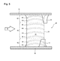
- the figure 5 represents a rectifier according to the invention whose blades are seen tangentially to the annular shape of the rectifier.
- the rectifier has a main blade 26 which extends radially between the inner ring 28 and the casing 30. At least one main blade 26 of the rectifier, preferably all the main blades of the rectifier have a first portion 60 and at least a second portion 62 arranged radially relative to each other.
- the first portion 60 may be an inner portion
- the second portion 62 may be an outer portion.
- the pressure face 40 is more axially curved than at the first portion 60. This feature allows the annular flow 18 to be moved away from the walls of the annular vein.
- the first portion 60 has profiles 64 whose neutral fibers 66 are essentially straight.
- the neutral fibers 66 of the profiles 64 of the second portion or portions 62 have mean radii of curvature less than the neutral fibers 66 of the profiles 64 of the first portion 60.
- the first portion 60 may be a central portion 60
- the second portion 62 may be a lateral portion 62.
- each main blade 26 comprises a second lateral portion 62, the central portion 60 being between the side portions.
- the pressure face 40 is more axially curved than at the first portion 60.
- the lateral portions 62 are connected to the annular walls of the rectifier.
- auxiliary blades 34 are associated with each second portion 62 of each main blade 26 of the rectifier.
- Auxiliary blades 34 extend radially mainly over the height of each second portion 62. They may extend, each, along 70% to 130%, preferably from 80% to 120%, more preferably from 90% to 110%. %, of the radial height of the second portion 62 associated with the associated main blade 26.
- each auxiliary blade 34 is between 70% and 130%, preferably between 80% and 120%, more preferably between 90% and 110%, of the radial height of the second portion 62 associated with the main blade 26. This feature aims to optimize the passage section in the primary flow 18 which is occupied by the auxiliary blades 34 with respect to the effect that they produce.
Abstract
L'invention a trait à un redresseur de compresseur ou de turbine de turbomachine axiale. Le redresseur comprend une rangée annulaire d'aubes statoriques principales (26) et des aubes auxiliaires (34) qui sont chacune associée à une aube principale (26). Les aubes auxiliaires (34) sont disposées au niveau des bords de fuite (38) des aubes principales (26) et sont à proximité des faces de pression (40) des aubes principales (26). Les aubes auxiliaires (34) sont configurées pour générer un espace en dépression (56) à hauteur des bords de fuite (38) des aubes principales (26). Ainsi, un flux contournant une aube principale (26) par sa face de dépression (42) est aspiré par l'espace en dépression (56) lorsqu'il se rapproche du bord de fuite (38) de l'aube principale (26). Son décollement est ainsi évité et le rendement de la machine est amélioré.The invention relates to a compressor or turbine turbomachine rectifier axial. The rectifier comprises an annular row of main stator vanes (26) and auxiliary vanes (34) which are each associated with a main vane (26). The auxiliary vanes (34) are disposed at the trailing edges (38) of the main vanes (26) and are proximate the pressure faces (40) of the main vanes (26). The auxiliary vanes (34) are configured to generate a vacuum space (56) at the trailing edges (38) of the main vanes (26). Thus, a flow bypassing a main blade (26) by its depression face (42) is sucked by the vacuum space (56) as it approaches the trailing edge (38) of the main blade (26) . Its detachment is thus avoided and the efficiency of the machine is improved.
Description
L'invention a trait à un redresseur de compresseur axial. Plus particulièrement, l'invention a trait à un redresseur de turbomachine comprenant des aubes principales et des aubes auxiliaires associées aux aubes principales. L'invention a trait également à une turbomachine axiale munie d'un redresseur selon l'invention.The invention relates to an axial compressor rectifier. More particularly, the invention relates to a turbomachine rectifier comprising main blades and auxiliary blades associated with the main blades. The invention also relates to an axial turbomachine provided with a rectifier according to the invention.
Afin de redresser leurs flux annulaires, les turbomachines axiales présentent des redresseurs. Ces grilles d'aubes sont disposées en aval de chaque rangée annulaire d'aubes rotoriques. Elles dévient un flux annulaire de sorte à transformer sa composante tangentielle en une composante axiale. Ce flux devient apte à être à nouveau accéléré par une autre rangée annulaire d'aubes rotoriques placée en aval.In order to straighten their annular flows, the axial turbomachines have rectifiers. These blade grids are disposed downstream of each annular row of rotor blades. They deviate an annular flow so as to transform its tangential component into an axial component. This flow becomes able to be accelerated again by another annular row of rotor blades placed downstream.
Un redresseur présente généralement une virole interne et une virole externe entre lesquelles s'étendent radialement les aubes statoriques. En fonctionnement, le flux annulaire peut se décoller des aubes, créant au passage de l'entropie qui réduit le rendement de la turbomachine.A rectifier generally has an inner ferrule and an outer ferrule between which the stator blades radially extend. In operation, the annular flow can be detached from the blades, creating the passage of the entropy that reduces the efficiency of the turbomachine.
Le document
Le document
L'invention a pour objectif de résoudre au moins un des problèmes soulevés par l'art antérieur. Plus précisément, l'invention a pour objectif d'améliorer la capacité d'un redresseur à redresser un flux. Plus précisément, l'invention a pour objectif de pouvoir augmenter la pression de sortie d'un redresseur aubagé. L'invention a également pour objectif d'améliorer le rendement d'un compresseur doté d'un redresseur aubagé.The invention aims to solve at least one of the problems raised by the prior art. More specifically, the invention aims to improve the ability of a rectifier to straighten a flow. More specifically, the object of the invention is to be able to increase the outlet pressure of a bladed rectifier. The invention also aims to improve the efficiency of a compressor with a bladed rectifier.
L'invention a trait à un redresseur axial de turbomachine axiale, comprenant: une rangée annulaire d'aubes statoriques principales s'étendant radialement, chacune desdits aubes comprenant une face de pression et une face de dépression; une série d'aubes statoriques auxiliaires disposées entre les aubes principales; remarquable en ce que chacune des aubes auxiliaires est associée à une des aubes principales en s'étendant le long et en aval de la face de pression de l'aube principale associée, à une distance, selon une direction circonférentielle, qui est inférieure à 30% de la distance entre deux aubes principales voisines.The invention relates to an axial axial turbomachine rectifier, comprising: an annular row of radially extending main stator vanes, each of said vanes comprising a pressure face and a vacuum face; a series of auxiliary stator vanes disposed between the main vanes; remarkable in that each of the auxiliary vanes is associated with one of the main vanes extending along and downstream from the pressure face of the associated main vane, at a distance, in a circumferential direction, which is less than 30 % of the distance between two neighboring main blades.
Selon un mode avantageux de l'invention, les aubes auxiliaires s'étendent essentiellement parallèlement à leurs aubes principales associées, respectivement.According to an advantageous embodiment of the invention, the auxiliary blades extend substantially parallel to their associated main blades, respectively.
Selon un mode avantageux de l'invention, les aubes auxiliaires chevauchent axialement les aubes principales associées sur une distance C comprise entre 5% et 50%, préférentiellement entre 10% et 30%, de leur longueur axiale.According to an advantageous embodiment of the invention, the auxiliary blades axially overlap the main blades associated over a distance C of between 5% and 50%, preferably between 10% and 30%, of their axial length.
Selon un mode avantageux de l'invention, le chevauchement axial entre les aubes auxiliaires et les aubes principales associées est limité à la distance C.According to an advantageous embodiment of the invention, the axial overlap between the auxiliary blades and the associated main blades is limited to the distance C.
Selon un mode avantageux de l'invention, la portion des aubes auxiliaires s'étendant depuis leur bord d'attaque sur 30% de la corde est à hauteur, selon une direction axiale, du bord de fuite des aubes principales associées respectives.According to an advantageous embodiment of the invention, the portion of the auxiliary blades extending from their leading edge on 30% of the rope is at a height, in an axial direction, the trailing edge of the respective associated main blades.
Selon un mode avantageux de l'invention, la longueur de la corde des aubes auxiliaires est inférieure, préférentiellement de 50%, plus préférentiellement de 40%, plus préférentiellement de 30%, à celle des aubes principales associées.According to an advantageous embodiment of the invention, the length of the rope of the auxiliary blades is less, preferably 50%, more preferably 40%, more preferably 30%, than that of the associated main blades.
Selon un mode avantageux de l'invention, la corde de chacune des aubes auxiliaires forme un angle α avec la corde des aubes principales associées respectives qui est compris entre 5° et 45°, préférentiellement entre 5° et 20°.According to an advantageous embodiment of the invention, the rope of each of the auxiliary blades forms an angle α with the rope of the respective associated main blades which is between 5 ° and 45 °, preferably between 5 ° and 20 °.
Selon un mode avantageux de l'invention, les aubes auxiliaires sont configurées et positionnées pour générer, lors du fonctionnement de la turbomachine, une dépression au niveau du bord de fuite des aubes principales associées, ladite dépression déviant par aspiration une partie du flux circulant du côté de la face en dépression des aubes principales associées vers ledit bord de fuite.According to an advantageous embodiment of the invention, the auxiliary blades are configured and positioned to generate, during operation of the turbomachine, a vacuum at the trailing edge of the associated main blades, said vacuum deviating a part of the circulating flow of the side of the negative side of the associated main blades towards said trailing edge.
Selon un mode avantageux de l'invention, chacune des aubes auxiliaires comporte une face de pression et une face de dépression, cette dernière étant en vis-à-vis de la face de pression de l'aube principale associée, la face de dépression de l'aube auxiliaire générant une dépression au niveau du bord de fuite de l'aube principale associée.According to an advantageous embodiment of the invention, each of the auxiliary blades comprises a pressure face and a vacuum face, the latter being opposite the pressure face of the associated main blade, the vacuum face of the auxiliary blade generating a depression at the trailing edge of the associated main blade.
Selon un mode avantageux de l'invention, la corde des aubes auxiliaires forme un angle avec la tangente de la face de pression des aubes principales associées au niveau du bord de fuite qui est inférieur à 20°, préférentiellement 15°, plus préférentiellement 10°.According to an advantageous embodiment of the invention, the rope of the auxiliary blades forms an angle with the tangent of the pressure face of the blades main associated with the trailing edge is less than 20 °, preferably 15 °, more preferably 10 °.
Selon un mode avantageux de l'invention, les aubes auxiliaires chevauchent axialement les aubes principales associées sur une distance C comprise entre 5% et 50%, préférentiellement entre 10% et 30%, de leur longueur axiale.According to an advantageous embodiment of the invention, the auxiliary blades axially overlap the main blades associated over a distance C of between 5% and 50%, preferably between 10% and 30%, of their axial length.
Selon un mode avantageux de l'invention, les aubes auxiliaires présentent une hauteur radiale comprise entre 10% et 100%, préférentiellement entre 10% et 50%, plus préférentiellement entre 15% et 25%, de la hauteur radiale des aubes principales associées.According to an advantageous embodiment of the invention, the auxiliary blades have a radial height of between 10% and 100%, preferably between 10% and 50%, more preferably between 15% and 25%, of the radial height of the associated main blades.
Selon un mode avantageux de l'invention, chaque aube principale comprend une première portion et une deuxième portion disposées radialement l'une par rapport à l'autre, à hauteur de la deuxième portion la face de pression est d'avantage incurvée axialement qu'au niveau de la première portion, chaque aube auxiliaire s'étendant radialement essentiellement le long de 80% à 120%, préférentiellement de 90% à 110%, de la hauteur radiale de la deuxième portion de l'aube principale associée.According to an advantageous embodiment of the invention, each main blade comprises a first portion and a second portion arranged radially relative to each other, at the level of the second portion, the pressure face is more axially curved than at the first portion, each auxiliary blade extending radially substantially along 80% to 120%, preferably 90% to 110%, of the radial height of the second portion of the associated main blade.
Selon un mode avantageux de l'invention, chaque aube auxiliaire présente une hauteur radiale comprise entre 80% et 120%, préférentiellement entre 90% et 110%, de la hauteur radiale de la deuxième portion de l'aube principale associée.According to an advantageous embodiment of the invention, each auxiliary blade has a radial height of between 80% and 120%, preferably between 90% and 110%, of the radial height of the second portion of the associated main blade.
Selon un mode avantageux de l'invention, le redresseur comprend une paroi annulaire externe et préférentiellement une paroi annulaire interne coaxiales avec la paroi annulaire externe, les aubes principales s'étendant radialement depuis la paroi annulaire externe, les aubes auxiliaires s'étendant radialement depuis la paroi annulaire externe et/ou depuis la paroi annulaire interne.According to an advantageous embodiment of the invention, the rectifier comprises an outer annular wall and preferably an inner annular wall coaxial with the outer annular wall, the main vanes extending radially from the outer annular wall, the auxiliary vanes extending radially from the outer annular wall and / or from the inner annular wall.
Selon un mode avantageux de l'invention, les aubes auxiliaires et la paroi annulaire ou une des parois annulaires depuis laquelle lesdites aubes s'étendent, sont venues de matière, préférentiellement en matériau composite ou en matériau métallique.According to an advantageous embodiment of the invention, the auxiliary blades and the annular wall or one of the annular walls from which said blades extend, are made of material, preferably of composite material or metal material.
Selon un mode avantageux de l'invention, une seule aube auxiliaire est associée à chacune des aubes principales.According to an advantageous embodiment of the invention, only one auxiliary blade is associated with each of the main blades.
Selon un mode avantageux de l'invention, une seule aube auxiliaire est présente entre deux aubes principales voisines.According to an advantageous embodiment of the invention, only one auxiliary blade is present between two adjacent main blades.
L'invention a également pour objet une turbomachine comprenant un compresseur et/ou une turbine avec au moins un redresseur, caractérisée en ce que le ou au moins un des redresseurs est conforme à l'invention.The invention also relates to a turbomachine comprising a compressor and / or a turbine with at least one rectifier, characterized in that the or at least one of the rectifiers is in accordance with the invention.
Suivant un mode avantageux de l'invention, la surface de chaque aube principale est supérieure à la surface de l'aube auxiliaire.According to an advantageous embodiment of the invention, the surface of each main blade is greater than the surface of the auxiliary blade.
Suivant un mode avantageux de l'invention, la rangée annulaire d'aubes principales comporte au moins une aube principale différente et/ou différemment agencée par rapport aux autres aubes principales de la rangée.According to an advantageous embodiment of the invention, the annular row of main blades comprises at least one main blade different and / or differently arranged relative to the other main blades of the row.
L'invention permet de réduire et/ou retarder le décrochage d'un flux contournant une aube principale du côté de sa face de dépression. Le décrochage peut être supprimé. L'invention permet ainsi d'augmenter l'appui procuré par les aubes au sein d'un redresseur et la capacité de ce dernier à redresser un flux est améliorée.The invention makes it possible to reduce and / or delay the stall of a flow bypassing a main blade on the side of its depression face. The stall can be removed. The invention thus increases the support provided by the blades within a rectifier and the ability of the latter to straighten a flow is improved.
Les aubes auxiliaires contribuent indirectement au redressement du flux. Elle apporte son concours à une aube principale en aspirant une partie du flux qui contourne cette dernière par la face de dépression. Elle contribue également de manière directe grâce à sa géométrie et à sa surface propre qui s'étend dans le flux.Auxiliary blades contribute indirectly to the recovery of the flow. It contributes to a main dawn by sucking a part of the flow that bypasses the latter by the face of depression. It also contributes in a direct way thanks to its geometry and its own surface which extends in the flow.
Le nombre d'aubes d'un tel redresseur pourra être réduit. Les couloirs entre ses aubes pourront être élargis, ce qui améliore à nouveau le rendement. En plus d'être allégé, ce redresseur sera plus économique à produire.The number of blades of such a rectifier can be reduced. The corridors between its vanes can be widened, which again improves the yield. In addition to being lightened, this rectifier will be more economical to produce.
L'invention permet d'améliorer le rendement d'un compresseur ou d'une turbine munis de tels redresseurs. Une turbomachine dotée d'un tel compresseur et/ou d'une telle turbine présentera une meilleure efficacité.The invention makes it possible to improve the efficiency of a compressor or a turbine provided with such rectifiers. A turbomachine equipped with such a compressor and / or such a turbine will have a better efficiency.
La
La
La
La
La
Dans la description qui va suivre, les termes intérieur ou interne et extérieur ou externe renvoient à un positionnement par rapport à l'axe de rotation d'une turbomachine axiale.In the following description, the terms inner or inner and outer or outer refer to a positioning relative to the axis of rotation of an axial turbomachine.
La
Un ventilateur d'entrée communément désigné fan 16 est couplé au rotor 12 et génère un flux d'air qui se divise en un flux primaire 18 traversant les différents niveaux sus mentionnés de la turbomachine, et un flux secondaire 20 traversant un conduit annulaire (partiellement représenté) le long de la machine pour ensuite rejoindre le flux primaire en sortie de turbine. Les flux primaire 18 et secondaire 20 sont des flux annulaires, ils sont canalisés par le carter de la turbomachine. A cet effet, le carter présente des parois cylindriques ou viroles internes et externes.A commonly designated fan inlet fan 16 is coupled to the rotor 12 and generates a flow of air which is divided into a
La
Le compresseur basse pression 4 comprend plusieurs redresseurs, en l'occurrence quatre, qui contiennent chacun une rangée d'aubes statoriques 26. Les redresseurs sont associés au fan 16 ou à une rangée d'aubes rotoriques pour redresser le flux d'air, de sorte à convertir la vitesse du flux en pression. Chaque réunion d'un redresseur et d'une rangée d'aubes rotoriques forme un étage de compression.The low pressure compressor 4 comprises several rectifiers, in this case four, each containing a row of
Un redresseur comprend au moins une paroi annulaire, préférentiellement deux parois annulaires, qui sont aptes à guider le flux annulaire primaire 18. Les parois annulaires peuvent être une virole interne 28 ou un carter extérieur 30. Au moins un des redresseurs peut comprendre une, préférentiellement plusieurs couches de matériau abradable 32. Avantageusement, le compresseur comprend des couches de matériau abradable 32 sous chaque virole interne 28 et sur le carter 30 au droit des extrémités externes de chaque rangée d'aubes rotoriques 24.A rectifier comprises at least one annular wall, preferably two annular walls, which are capable of guiding the primary
Les aubes statoriques 26 s'étendent essentiellement radialement depuis le carter extérieur 30 jusqu'à leur virole interne 28 associée. Celle-ci est fixée à l'extrémité intérieure des aubes statoriques 26. Ces dernières sont régulièrement espacés les unes des autres, et présentent une même orientation angulaire dans le flux. Avantageusement, ces aubes sont identiques. Eventuellement, l'espacement entre les aubes statoriques peut varier localement tout comme leur orientation angulaire. Certaines aubes statoriques peuvent être différentes du reste des aubes de la rangée.The stator vanes 26 extend substantially radially from the
Les aubes statoriques 26 sont des aubes statoriques principales 26. Au moins un des redresseurs est muni d'au moins une aube statorique auxiliaire 34, qui est disposée en aval d'une de ses aubes principales 26. Préférentiellement, chaque aube principale 26 d'un même redresseur est munie d'une aube auxiliaire 34. L'ensemble d'aubes auxiliaires 34 d'un redresseur forme une rangée annulaire d'aubes. Préférentiellement encore, tous les redresseurs sont munis d'aubes auxiliaires 34.The stator vanes 26 are main stator vanes 26. At least one of the rectifiers is provided with at least one
Les aubes auxiliaires 34 s'étendent radialement depuis une paroi annulaire (28, 30). Une même aube principale 26 peut être munie de deux aubes auxiliaires 34. L'une s'étend radialement depuis une virole interne 28, l'autre depuis le carter extérieur 30. Les extrémités de ces deux aubes auxiliaires 34 sont distantes l'une de l'autre. Eventuellement, toutes les aubes d'un même redresseur sont munies de deux aubes auxiliaires 34.The
Une virole interne 28 et ses aubes auxiliaires 34 peuvent être venues de matière. Une portion de carter extérieur 30 et ses aubes auxiliaires 34 peuvent être venues de matière. A cet effet, le carter extérieur 30 peut être formé de plusieurs viroles extérieures appartenant chacune à un redresseur. Un redresseur peut être segmenté. Un redresseur ou un segment de redresseur peut être venu de matière. Un redresseur ou un segment de redresseur peut être réalisé en matériaux composites et être injecté, ou être en matériaux métalliques et être usiné par électroérosion.An
La
Le redresseur comprend des aubes principales 26 et des aubes auxiliaires 34 qui sont chacune associées à une aube principale 26. Les aubes principales 26 présentent chacune un bord d'attaque 36 et un bord de fuite 38. Elles présentent chacune une face 40 destinée à travailler en pression et une face 42 destinée à travailler en dépression. Ces faces s'étendent du bord d'attaque 36 au bord de fuite 38 de l'aube. Les aubes principales peuvent être cambrées localement ou sur toute leur hauteur. Les cordes 44 des aubes principales 26 sont habituellement inclinées par rapport à l'axe 14 de rotation de la turbomachine.The rectifier comprises
Les aubes auxiliaires 34 sont disposées axialement à hauteur des bords de fuite 38 des aubes principales 26, entre lesdites aubes. Chacune des aubes auxiliaires 34 est associée à un aube principale 26 en étant disposée au voisinage du bord de fuite 38 de ladite aube. Les aubes auxiliaires 34 présentent chacune un bord d'attaque 46 et un bord de fuite 48. Elles comprennent chacune une face destinée à travailler en pression 50 et une face destinée à travailler en dépression 52. Ces faces s'étendent d'un bord d'attaque 46 à un bord de fuite 48 de l'aube. La face de dépression 52 d'une aube auxiliaire 34 est en regard de la face de pression 40 de l'aube principale 26 associée.The
L'écartement entre les aubes principales 26 est supérieur au double de la distance entre une aube principale 26 et une aube auxiliaire 34 associée. La distance D1 entre les bords d'attaque 36 des aubes principales 26 est supérieure au double de la distance tangentielle D2 entre le bord de fuite 38 d'une aube principale 26 et le bord d'attaque 46 d'une aube auxiliaire 34 associée, préferentiellement supérieure au quadruple, plus préférentiellement supérieure au décuple.The spacing between the
Les aubes principales 26 et les aubes auxiliaires 34 se chevauchent axialement. Ce chevauchement axial C est compris entre 1% et 90% de la longueur des aubes auxiliaires 34, préférentiellement compris entre 10% et 60%, plus préférentiellement compris entre 20% et 40%.The
Les cordes 54 des aubes auxiliaires 34 sont inclinées par rapport aux cordes 44 des aubes principales 26. L'inclinaison α est comprise entre 1° et 30°, préférentiellement comprise entre 5° et 20°, plus préférentiellement comprise entre 8° et 12°. L'inclinaison des cordes 44 des aubes principales 26 par rapport à l'axe 14 du redresseur est supérieure à l'inclinaison des cordes 54 aubes auxiliaires par rapport à l'axe 14 du redresseur, préférentiellement généralement deux fois supérieure.The
La
L'aube auxiliaire 34 est configurée pour créer une dépression 56 locale dans le flux redressé par le redresseur. Cette dépression 56 occupe un espace en dépression 56 qui s'étend axialement et radialement. Il s'étend radialement sur essentiellement la hauteur de l'aube auxiliaire 34. Il s'étend également tangentiellement jusqu'à la face de pression de l'aube principale 26 et préférentiellement au-delà de la face de dépression de l'aube principale 26. Il s'étend axialement en aval du bord de fuite 38 de l'aube principale 26.The
Grâce à cette configuration, le flux primaire 18 issu des aubes de rotor suit davantage la face de dépression 42 de l'aube principale 26. De ce côté, les trajectoires du flux sont représentées à l'aide de lignes de flux 58. Certaines de ces lignes épousent la face de dépression 42 de l'aube principale. Celles qui sont le plus proches de cette face sont mêmes aspirées par l'espace en dépression 56 à l'approche des bords de fuite 38 de l'aube principale 26.With this configuration, the
Remarquons que la ligne de flux la plus éloignée de l'aube principale 26 se décole du contour de la face de dépression. Cette ligne de flux n'est pas redressée sur toute la longueur de l'aube principale 26. Il est à préciser qu'en l'absence de l'aube auxiliaire 34, l'ensemble des lignes de flux se décoleraient avant d'atteindre le bord de fuite de l'aube principale 26, ce qui réduirait l'efficacité du redresseur. L'invention permet donc d'améliorer la capacité du redresseur à redresser un flux. Il retarde et/ou réduit les décolements de flux. Eventuellement, il les supprime. Ainsi l'appui de chaque aube principale est amélioré. L'efficacité apportée par chaque aube principale d'un redresseur est accru, si bien qu'il devient possible d'en réduire le nombre. En plus de représenter une économie, cette conséquence permet encore d'améliorer le rendement du redresseur.Note that the flow line farthest from the
Pour générer un espace en dépression 56, l'aube auxiliaire 34 peut présenter différentes particularités. Elle peut présenter une corde 54 qui est inclinée par rapport à la corde de l'aube principale 26, son inclinaison par rapport à l'axe du redresseur étant moins marquée que celle de l'aube principale 26. Afin de créer une dépression tout en participant à redresser le flux, l'aube auxiliaire 34 et/ou sa corde 54 peuvent être généralement parallèles au bord de fuite 38 de l'aube principale 26.To generate a
En complément ou en alternative, l'aube auxiliaire 34 peut présenter une cambrure. Son profil peut également montrer une variation d'épaisseur. De la sorte, sa face de pression 50 et sa face de dépression 52 présentent des longueurs significativement différentes. La dépression sera d'autant plus importante sur la face de dépression 52.In addition or alternatively, the
L'espace en dépression 56 est généralement généré en partie amont de l'aube auxiliaire 34. Ceci découle du fait qu'à cet endroit le flux subit les accélérations les plus fortes. L'espace en dépression 56 s'étend conventionnellement sur le premier tiers amont de l'aube auxiliaire 34. Il est donc judicieux de disposer les deux aubes l'une par rapport à l'autre de sorte à ce que le bord de fuite 38 de l'aube principale 26 soit implanté axialement dans le premier tiers amont de l'aube auxiliaire 34.The
L'espace en dépression 56 peut être généralement symétrique axialement. Par conséquent, le bord de fuite 38 de l'aube principale 26 peut être disposé axialement de sorte à être reculé par rapport au bord d'attaque 46 de l'aube auxiliaire 34 d'un sixième de sa corde. Ainsi, le bord de fuite 38 de l'aube principale 26 sera positionnée au maximum de dépression possible pour une distance D2 donnée.The
La
Le redresseur présente une aube principale 26 qui s'étend radialement entre la virole interne 28 et le carter 30. Au moins une aube principale 26 du redresseur, préférentiellement toutes les aubes principales du redresseur présentent une première portion 60 et au moins une deuxième portion 62 disposées radialement l'une par rapport à l'autre. La première portion 60 peut être une portion intérieure, et la deuxième portion 62 peut être une portion externe. A hauteur radialement de la ou d'au moins une des deuxièmes portions 62, la face de pression 40 est d'avantage incurvée axialement qu'au niveau de la première portion 60. Cette particularité permet d'éloigner le flux annulaire 18 de la ou des parois de la veine annulaire.The rectifier has a
Le caractère incurvé axialement s'observe dans la direction tangentielle en se déplaçant axialement le long de la face de pression 40 de l'aube principale. Eventuellement, la première portion 60 présente des profils 64 dont les fibres neutres 66 sont essentiellement droites. Les fibres neutres 66 des profils 64 de la ou des deuxièmes portions 62 présentent des rayons de courbure moyens inférieurs aux fibres neutres 66 des profils 64 de la première portion 60.The axially curved character is observed in the tangential direction by moving axially along the
La première portion 60 peut être une portion centrale 60, et la deuxième portion 62 peut être une portion latérale 62. Suivant un mode avantageux de l'invention, chaque aube principale 26 comprend une deuxième portion latérale 62, la portion centrale 60 étant entre les portions latérales. Au niveau des deux portions latérales 62, la face de pression 40 est d'avantage incurvée axialement qu'au niveau de la première portion 60. Les portions latérale 62 sont reliées aux parois annulaires du redresseur.The
Les portions latérales 62 sont celles où un décolement de flux sur la face de dépression 40 est le plus susceptibles de se produire. Il est donc judicieux d'y disposer des aubes auxiliaires 34 au droit des bords de fuite 38. Avantageusement, une aube auxiliaire 34 est associée à chaque deuxième portion 62 de chaque aube principale 26 du redresseur. Les aubes auxiliaires 34 s'étendent radialement principalement sur la hauteur de chaque deuxième portion 62. Elles peuvent s'étendre, chacune, le long de 70% à 130%, préférentiellement de 80% à 120%, plus préférentiellement de 90% à 110%, de la hauteur radiale de la deuxième portion 62 associée de l'aube principale associée 26. La hauteur radiale de chaque aube auxiliaire 34 est comprise entre 70% et 130%, préférentiellement entre 80% et 120%, plus préférentiellement entre 90% et 110%, de la hauteur radiale de la deuxième portion 62 associée de l'aube principale 26. Cette particularité vise à optimiser la section de passage dans le flux primaire 18 qui est occupé par les aubes auxiliaires 34 par rapport à l'effet qu'elles produisent.The
Claims (15)
caractérisé en ce que
chacune des aubes auxiliaires (34) est associée à une des aubes principales (26) en s'étendant le long et en aval de la face de pression (40) de l'aube principale associée, à une distance, selon une direction circonférentielle, qui est inférieure à 30% de la distance entre deux aubes principales (26) voisines.
characterized in that
each of the auxiliary blades (34) is associated with one of the main blades (26) extending along and downstream of the pressure face (40) of the associated main blade, at a distance, in a circumferential direction, which is less than 30% of the distance between two adjacent main blades (26).
Priority Applications (5)
| Application Number | Priority Date | Filing Date | Title |
|---|---|---|---|
| EP13166527.5A EP2799721B8 (en) | 2013-05-03 | 2013-05-03 | Axial turbomachine stator guide with auxiliary vanes on the vane feet |
| CA2849651A CA2849651C (en) | 2013-05-03 | 2014-04-23 | Axial turbomachine stator with ailerons at the blade roots |
| CN201410178090.3A CN104131845B (en) | 2013-05-03 | 2014-04-29 | There is the axial-flow turbine machine stator of aileron in root of blade |
| RU2014117435/06A RU2586426C2 (en) | 2013-05-03 | 2014-04-30 | Stator of axial turbo machine with ailerons in blade roots |
| US14/268,799 US9739154B2 (en) | 2013-05-03 | 2014-05-02 | Axial turbomachine stator with ailerons at the blade roots |
Applications Claiming Priority (1)
| Application Number | Priority Date | Filing Date | Title |
|---|---|---|---|
| EP13166527.5A EP2799721B8 (en) | 2013-05-03 | 2013-05-03 | Axial turbomachine stator guide with auxiliary vanes on the vane feet |
Publications (3)
| Publication Number | Publication Date |
|---|---|
| EP2799721A1 true EP2799721A1 (en) | 2014-11-05 |
| EP2799721B1 EP2799721B1 (en) | 2016-09-07 |
| EP2799721B8 EP2799721B8 (en) | 2016-12-07 |
Family
ID=48288885
Family Applications (1)
| Application Number | Title | Priority Date | Filing Date |
|---|---|---|---|
| EP13166527.5A Active EP2799721B8 (en) | 2013-05-03 | 2013-05-03 | Axial turbomachine stator guide with auxiliary vanes on the vane feet |
Country Status (5)
| Country | Link |
|---|---|
| US (1) | US9739154B2 (en) |
| EP (1) | EP2799721B8 (en) |
| CN (1) | CN104131845B (en) |
| CA (1) | CA2849651C (en) |
| RU (1) | RU2586426C2 (en) |
Cited By (3)
| Publication number | Priority date | Publication date | Assignee | Title |
|---|---|---|---|---|
| EP3163028A1 (en) * | 2015-10-26 | 2017-05-03 | General Electric Company | Compressor apparatus |
| US9938984B2 (en) | 2014-12-29 | 2018-04-10 | General Electric Company | Axial compressor rotor incorporating non-axisymmetric hub flowpath and splittered blades |
| FR3116299A1 (en) * | 2020-11-13 | 2022-05-20 | Safran Helicopter Engines | turbomachine compressor |
Families Citing this family (22)
| Publication number | Priority date | Publication date | Assignee | Title |
|---|---|---|---|---|
| DE102014203604A1 (en) * | 2014-02-27 | 2015-08-27 | Rolls-Royce Deutschland Ltd & Co Kg | Blade row group |
| US9874221B2 (en) * | 2014-12-29 | 2018-01-23 | General Electric Company | Axial compressor rotor incorporating splitter blades |
| CN105422186B (en) * | 2015-12-18 | 2017-10-24 | 清华大学 | Axial-flow turbine with leaflet chip architecture |
| CN105864105A (en) * | 2016-04-25 | 2016-08-17 | 西北工业大学 | Axial flow compressor stator with in-vitro small blades in hub corner area |
| US10151322B2 (en) * | 2016-05-20 | 2018-12-11 | United Technologies Corporation | Tandem tip blade |
| US20180017079A1 (en) * | 2016-07-15 | 2018-01-18 | General Electric Company | Variable-cycle compressor with a splittered rotor |
| US20180017019A1 (en) * | 2016-07-15 | 2018-01-18 | General Electric Company | Turbofan engine wth a splittered rotor fan |
| US10502220B2 (en) | 2016-07-22 | 2019-12-10 | Solar Turbines Incorporated | Method for improving turbine compressor performance |
| US20180306041A1 (en) * | 2017-04-25 | 2018-10-25 | General Electric Company | Multiple turbine vane frame |
| US10883515B2 (en) | 2017-05-22 | 2021-01-05 | General Electric Company | Method and system for leading edge auxiliary vanes |
| US11002141B2 (en) * | 2017-05-22 | 2021-05-11 | General Electric Company | Method and system for leading edge auxiliary turbine vanes |
| US10385871B2 (en) * | 2017-05-22 | 2019-08-20 | General Electric Company | Method and system for compressor vane leading edge auxiliary vanes |
| DE102017212311A1 (en) | 2017-07-19 | 2019-01-24 | MTU Aero Engines AG | Umströmungsanordung for arranging in the hot gas duct of a turbomachine |
| WO2019236062A1 (en) * | 2018-06-05 | 2019-12-12 | Siemens Energy, Inc. | Arrangement of a last stage with flow blockers and corresponding method for suppressing rotating flow instability cells |
| EP3608505B1 (en) | 2018-08-08 | 2021-06-23 | General Electric Company | Turbine incorporating endwall fences |
| BE1026884B1 (en) | 2018-12-18 | 2020-07-22 | Safran Aero Boosters Sa | Stator stage of a compressor of an aircraft turbomachine |
| US11401824B2 (en) * | 2019-10-15 | 2022-08-02 | General Electric Company | Gas turbine engine outlet guide vane assembly |
| US11149552B2 (en) | 2019-12-13 | 2021-10-19 | General Electric Company | Shroud for splitter and rotor airfoils of a fan for a gas turbine engine |
| BE1027876B1 (en) * | 2019-12-18 | 2021-07-26 | Safran Aero Boosters Sa | TURBOMACHINE MODULE |
| BE1029074B1 (en) | 2021-02-02 | 2022-08-29 | Safran Aero Boosters | AIRCRAFT TURBOMACHINE COMPRESSOR RECTIFIER ASSEMBLY |
| IT202100002240A1 (en) | 2021-02-02 | 2022-08-02 | Gen Electric | TURBINE ENGINE WITH REDUCED TRANSVERSE FLOW VANES |
| FR3139854A1 (en) * | 2022-09-19 | 2024-03-22 | Safran Aircraft Engines | Inter-turbine casing |
Citations (7)
| Publication number | Priority date | Publication date | Assignee | Title |
|---|---|---|---|---|
| US3039736A (en) * | 1954-08-30 | 1962-06-19 | Pon Lemuel | Secondary flow control in fluid deflecting passages |
| GB1299686A (en) * | 1970-03-23 | 1972-12-13 | Cit Alcatel | A supersonic axial-flow compressor |
| JP2001027103A (en) * | 1999-07-14 | 2001-01-30 | Ishikawajima Harima Heavy Ind Co Ltd | Stationary blade structure for axial turbo-machine |
| EP1122407A2 (en) * | 2000-02-02 | 2001-08-08 | Rolls Royce Plc | Controllable guide vane apparatus for a gas turbine engine |
| EP1927723B1 (en) | 2006-11-28 | 2009-10-28 | Deutsches Zentrum für Luft- und Raumfahrt e.V. | Stator stage of an axial compressor in a flow engine with transverse fins to increase the action |
| FR2939852A1 (en) | 2008-12-15 | 2010-06-18 | Snecma | Stator blade stage for compressor of turboshaft engine e.g. turbopropeller engine, has intermediate blades with axial length or radial height less than that of rectifier blades and extend radially between rectifier blades |
| US20120243983A1 (en) * | 2011-03-25 | 2012-09-27 | Andrew Breeze-Stringfellow | High camber stator vane |
Family Cites Families (14)
| Publication number | Priority date | Publication date | Assignee | Title |
|---|---|---|---|---|
| GB628263A (en) * | 1943-06-01 | 1949-08-25 | Louis Breguet | Improvements in or relating to axial flow compressors |
| US2839239A (en) * | 1954-06-02 | 1958-06-17 | Edward A Stalker | Supersonic axial flow compressors |
| US3075743A (en) * | 1958-10-20 | 1963-01-29 | Gen Dynamics Corp | Turbo-machine with slotted blades |
| BE638547A (en) * | 1962-10-29 | 1900-01-01 | ||
| US3692425A (en) * | 1969-01-02 | 1972-09-19 | Gen Electric | Compressor for handling gases at velocities exceeding a sonic value |
| US4512718A (en) * | 1982-10-14 | 1985-04-23 | United Technologies Corporation | Tandem fan stage for gas turbine engines |
| SU1366722A1 (en) * | 1985-04-15 | 1988-01-15 | Университет дружбы народов им.Патриса Лумумбы | Double-row blade system of axial compressor |
| US4981414A (en) * | 1988-05-27 | 1991-01-01 | Sheets Herman E | Method and apparatus for producing fluid pressure and controlling boundary layer |
| JPH04287802A (en) * | 1991-03-19 | 1992-10-13 | Hitachi Ltd | Steam turbine nozzle |
| JPH06207504A (en) * | 1993-01-11 | 1994-07-26 | Ishikawajima Harima Heavy Ind Co Ltd | Stationary blade structure of compressor for engine |
| CN100494640C (en) * | 2007-11-29 | 2009-06-03 | 北京航空航天大学 | Big and small blade tandem blade cascade impeller and compressor |
| RU2397351C2 (en) * | 2008-08-01 | 2010-08-20 | Николай Евгеньевич Староверов | Turbine engine (versions) |
| DE102009013399A1 (en) * | 2009-03-16 | 2010-09-23 | Mtu Aero Engines Gmbh | Tandem blade design |
| CN102052095B (en) * | 2010-07-07 | 2013-12-04 | 北京全四维动力科技有限公司 | Asymmetric diaphragm static cascade and asymmetric blades in nozzle set for axial flow steam turbine |
-
2013
- 2013-05-03 EP EP13166527.5A patent/EP2799721B8/en active Active
-
2014
- 2014-04-23 CA CA2849651A patent/CA2849651C/en active Active
- 2014-04-29 CN CN201410178090.3A patent/CN104131845B/en active Active
- 2014-04-30 RU RU2014117435/06A patent/RU2586426C2/en active
- 2014-05-02 US US14/268,799 patent/US9739154B2/en active Active
Patent Citations (7)
| Publication number | Priority date | Publication date | Assignee | Title |
|---|---|---|---|---|
| US3039736A (en) * | 1954-08-30 | 1962-06-19 | Pon Lemuel | Secondary flow control in fluid deflecting passages |
| GB1299686A (en) * | 1970-03-23 | 1972-12-13 | Cit Alcatel | A supersonic axial-flow compressor |
| JP2001027103A (en) * | 1999-07-14 | 2001-01-30 | Ishikawajima Harima Heavy Ind Co Ltd | Stationary blade structure for axial turbo-machine |
| EP1122407A2 (en) * | 2000-02-02 | 2001-08-08 | Rolls Royce Plc | Controllable guide vane apparatus for a gas turbine engine |
| EP1927723B1 (en) | 2006-11-28 | 2009-10-28 | Deutsches Zentrum für Luft- und Raumfahrt e.V. | Stator stage of an axial compressor in a flow engine with transverse fins to increase the action |
| FR2939852A1 (en) | 2008-12-15 | 2010-06-18 | Snecma | Stator blade stage for compressor of turboshaft engine e.g. turbopropeller engine, has intermediate blades with axial length or radial height less than that of rectifier blades and extend radially between rectifier blades |
| US20120243983A1 (en) * | 2011-03-25 | 2012-09-27 | Andrew Breeze-Stringfellow | High camber stator vane |
Cited By (5)
| Publication number | Priority date | Publication date | Assignee | Title |
|---|---|---|---|---|
| US9938984B2 (en) | 2014-12-29 | 2018-04-10 | General Electric Company | Axial compressor rotor incorporating non-axisymmetric hub flowpath and splittered blades |
| EP3163028A1 (en) * | 2015-10-26 | 2017-05-03 | General Electric Company | Compressor apparatus |
| CN107035435A (en) * | 2015-10-26 | 2017-08-11 | 通用电气公司 | With reference to the compressor of current divider |
| CN107035435B (en) * | 2015-10-26 | 2019-05-31 | 通用电气公司 | In conjunction with the compressor of current divider |
| FR3116299A1 (en) * | 2020-11-13 | 2022-05-20 | Safran Helicopter Engines | turbomachine compressor |
Also Published As
| Publication number | Publication date |
|---|---|
| CA2849651A1 (en) | 2014-11-03 |
| US20140328675A1 (en) | 2014-11-06 |
| CA2849651C (en) | 2018-10-09 |
| EP2799721B8 (en) | 2016-12-07 |
| RU2586426C2 (en) | 2016-06-10 |
| RU2014117435A (en) | 2015-11-10 |
| CN104131845A (en) | 2014-11-05 |
| US9739154B2 (en) | 2017-08-22 |
| EP2799721B1 (en) | 2016-09-07 |
| CN104131845B (en) | 2017-04-05 |
Similar Documents
| Publication | Publication Date | Title |
|---|---|---|
| EP2799721B1 (en) | Axial turbomachine stator guide with auxiliary vanes on the vane feet | |
| CA2837819C (en) | Turbomachine element with swirl generating devices | |
| EP2977549B1 (en) | Axial turbomachine blading and corresponding turbomachine | |
| BE1024684B1 (en) | AXIAL TURBOMACHINE COMPRESSOR DEGIVER | |
| EP3273003B1 (en) | Vane segment of an axial turbomachine compressor | |
| FR3014943A1 (en) | TURBOMACHINE PIECE WITH NON-AXISYMETRIC SURFACE | |
| BE1026579B1 (en) | PROTUBERANCE VANE FOR TURBOMACHINE COMPRESSOR | |
| EP2803822B1 (en) | Air-bleeding system of an axial turbomachine | |
| EP2977548B1 (en) | Blade and corresponding turbomachine | |
| EP2795068B1 (en) | Turbomachine compressor guide vanes assembly | |
| EP2669475A1 (en) | S-shaped profile blade of axial turbomachine compressor, corresponding compressor and turbomachine | |
| EP3477050B1 (en) | Turbomachine compressor with asymmetricly contoured wall ring | |
| EP3477049B1 (en) | Turbine engine compressor with ring comprising elevations | |
| EP2979808B1 (en) | Method for manufacturing a stator of an axial turbomachine compressor | |
| FR3063118A1 (en) | TURBOMACHINE PIECE ASSEMBLY WITH AN INTEGRATED PLATFORM VANE AND CORRESPONDING TURBOMACHINE | |
| BE1023215A1 (en) | VORTEX INJECTOR CASING FOR AXIAL TURBOMACHINE COMPRESSOR | |
| EP3803055B1 (en) | Contoured shroud for a compressor of a turbomachine | |
| BE1025131B1 (en) | DOUBLE-CURVED TRANSMISSION SHAFT FOR TURBOMACHINE | |
| EP2977550B1 (en) | Axial turbomachine blade and corresponding turbomachine | |
| BE1024743B1 (en) | LOW AXIAL TURBOMACHINE COMPRESSOR | |
| BE1024523B1 (en) | ADJUSTABLE AUTON STATOR FOR AXIAL TURBOMACHINE COMPRESSOR | |
| JP6431674B2 (en) | Turbine casing inlet assembly structure | |
| BE1025984B1 (en) | LOW PRESSURE COMPRESSOR VEIN FOR TURBOMACHINE | |
| WO2024033065A1 (en) | Variable vane of an aircraft turbine engine stator, and aircraft turbine engine | |
| BE1024699B1 (en) | LOW MEMORY PRESSURE COMPRESSOR FOR AXIAL TURBOMACHINE |
Legal Events
| Date | Code | Title | Description |
|---|---|---|---|
| PUAI | Public reference made under article 153(3) epc to a published international application that has entered the european phase |
Free format text: ORIGINAL CODE: 0009012 |
|
| 17P | Request for examination filed |
Effective date: 20130503 |
|
| AK | Designated contracting states |
Kind code of ref document: A1 Designated state(s): AL AT BE BG CH CY CZ DE DK EE ES FI FR GB GR HR HU IE IS IT LI LT LU LV MC MK MT NL NO PL PT RO RS SE SI SK SM TR |
|
| AX | Request for extension of the european patent |
Extension state: BA ME |
|
| R17P | Request for examination filed (corrected) |
Effective date: 20150504 |
|
| RBV | Designated contracting states (corrected) |
Designated state(s): AL AT BE BG CH CY CZ DE DK EE ES FI FR GB GR HR HU IE IS IT LI LT LU LV MC MK MT NL NO PL PT RO RS SE SI SK SM TR |
|
| GRAP | Despatch of communication of intention to grant a patent |
Free format text: ORIGINAL CODE: EPIDOSNIGR1 |
|
| INTG | Intention to grant announced |
Effective date: 20160321 |
|
| GRAS | Grant fee paid |
Free format text: ORIGINAL CODE: EPIDOSNIGR3 |
|
| GRAA | (expected) grant |
Free format text: ORIGINAL CODE: 0009210 |
|
| RAP1 | Party data changed (applicant data changed or rights of an application transferred) |
Owner name: SAFRAN AERO BOOSTER S.A. |
|
| AK | Designated contracting states |
Kind code of ref document: B1 Designated state(s): AL AT BE BG CH CY CZ DE DK EE ES FI FR GB GR HR HU IE IS IT LI LT LU LV MC MK MT NL NO PL PT RO RS SE SI SK SM TR |
|
| REG | Reference to a national code |
Ref country code: GB Ref legal event code: FG4D Free format text: NOT ENGLISH |
|
| REG | Reference to a national code |
Ref country code: CH Ref legal event code: EP |
|
| GRAT | Correction requested after decision to grant or after decision to maintain patent in amended form |
Free format text: ORIGINAL CODE: EPIDOSNCDEC |
|
| REG | Reference to a national code |
Ref country code: IE Ref legal event code: FG4D Free format text: LANGUAGE OF EP DOCUMENT: FRENCH |
|
| REG | Reference to a national code |
Ref country code: AT Ref legal event code: REF Ref document number: 827151 Country of ref document: AT Kind code of ref document: T Effective date: 20161015 |
|
| REG | Reference to a national code |
Ref country code: DE Ref legal event code: R096 Ref document number: 602013011037 Country of ref document: DE |
|
| REG | Reference to a national code |
Ref country code: DE Ref legal event code: R081 Ref document number: 602013011037 Country of ref document: DE Owner name: SAFRAN AERO BOOSTERS S.A., BE Free format text: FORMER OWNER: SAFRAN AERO BOOSTER S.A., HERSTAL, BE |
|
| REG | Reference to a national code |
Ref country code: LT Ref legal event code: MG4D |
|
| REG | Reference to a national code |
Ref country code: NL Ref legal event code: MP Effective date: 20160907 |
|
| PG25 | Lapsed in a contracting state [announced via postgrant information from national office to epo] |
Ref country code: NO Free format text: LAPSE BECAUSE OF FAILURE TO SUBMIT A TRANSLATION OF THE DESCRIPTION OR TO PAY THE FEE WITHIN THE PRESCRIBED TIME-LIMIT Effective date: 20161207 Ref country code: RS Free format text: LAPSE BECAUSE OF FAILURE TO SUBMIT A TRANSLATION OF THE DESCRIPTION OR TO PAY THE FEE WITHIN THE PRESCRIBED TIME-LIMIT Effective date: 20160907 Ref country code: HR Free format text: LAPSE BECAUSE OF FAILURE TO SUBMIT A TRANSLATION OF THE DESCRIPTION OR TO PAY THE FEE WITHIN THE PRESCRIBED TIME-LIMIT Effective date: 20160907 Ref country code: LT Free format text: LAPSE BECAUSE OF FAILURE TO SUBMIT A TRANSLATION OF THE DESCRIPTION OR TO PAY THE FEE WITHIN THE PRESCRIBED TIME-LIMIT Effective date: 20160907 Ref country code: FI Free format text: LAPSE BECAUSE OF FAILURE TO SUBMIT A TRANSLATION OF THE DESCRIPTION OR TO PAY THE FEE WITHIN THE PRESCRIBED TIME-LIMIT Effective date: 20160907 |
|
| REG | Reference to a national code |
Ref country code: AT Ref legal event code: MK05 Ref document number: 827151 Country of ref document: AT Kind code of ref document: T Effective date: 20160907 |
|
| PG25 | Lapsed in a contracting state [announced via postgrant information from national office to epo] |
Ref country code: ES Free format text: LAPSE BECAUSE OF FAILURE TO SUBMIT A TRANSLATION OF THE DESCRIPTION OR TO PAY THE FEE WITHIN THE PRESCRIBED TIME-LIMIT Effective date: 20160907 Ref country code: NL Free format text: LAPSE BECAUSE OF FAILURE TO SUBMIT A TRANSLATION OF THE DESCRIPTION OR TO PAY THE FEE WITHIN THE PRESCRIBED TIME-LIMIT Effective date: 20160907 Ref country code: LV Free format text: LAPSE BECAUSE OF FAILURE TO SUBMIT A TRANSLATION OF THE DESCRIPTION OR TO PAY THE FEE WITHIN THE PRESCRIBED TIME-LIMIT Effective date: 20160907 Ref country code: SE Free format text: LAPSE BECAUSE OF FAILURE TO SUBMIT A TRANSLATION OF THE DESCRIPTION OR TO PAY THE FEE WITHIN THE PRESCRIBED TIME-LIMIT Effective date: 20160907 Ref country code: GR Free format text: LAPSE BECAUSE OF FAILURE TO SUBMIT A TRANSLATION OF THE DESCRIPTION OR TO PAY THE FEE WITHIN THE PRESCRIBED TIME-LIMIT Effective date: 20161208 |
|
| REG | Reference to a national code |
Ref country code: FR Ref legal event code: PLFP Year of fee payment: 5 |
|
| PG25 | Lapsed in a contracting state [announced via postgrant information from national office to epo] |
Ref country code: EE Free format text: LAPSE BECAUSE OF FAILURE TO SUBMIT A TRANSLATION OF THE DESCRIPTION OR TO PAY THE FEE WITHIN THE PRESCRIBED TIME-LIMIT Effective date: 20160907 Ref country code: RO Free format text: LAPSE BECAUSE OF FAILURE TO SUBMIT A TRANSLATION OF THE DESCRIPTION OR TO PAY THE FEE WITHIN THE PRESCRIBED TIME-LIMIT Effective date: 20160907 |
|
| PG25 | Lapsed in a contracting state [announced via postgrant information from national office to epo] |
Ref country code: AT Free format text: LAPSE BECAUSE OF FAILURE TO SUBMIT A TRANSLATION OF THE DESCRIPTION OR TO PAY THE FEE WITHIN THE PRESCRIBED TIME-LIMIT Effective date: 20160907 Ref country code: IS Free format text: LAPSE BECAUSE OF FAILURE TO SUBMIT A TRANSLATION OF THE DESCRIPTION OR TO PAY THE FEE WITHIN THE PRESCRIBED TIME-LIMIT Effective date: 20170107 Ref country code: SK Free format text: LAPSE BECAUSE OF FAILURE TO SUBMIT A TRANSLATION OF THE DESCRIPTION OR TO PAY THE FEE WITHIN THE PRESCRIBED TIME-LIMIT Effective date: 20160907 Ref country code: BG Free format text: LAPSE BECAUSE OF FAILURE TO SUBMIT A TRANSLATION OF THE DESCRIPTION OR TO PAY THE FEE WITHIN THE PRESCRIBED TIME-LIMIT Effective date: 20161207 Ref country code: SM Free format text: LAPSE BECAUSE OF FAILURE TO SUBMIT A TRANSLATION OF THE DESCRIPTION OR TO PAY THE FEE WITHIN THE PRESCRIBED TIME-LIMIT Effective date: 20160907 Ref country code: PT Free format text: LAPSE BECAUSE OF FAILURE TO SUBMIT A TRANSLATION OF THE DESCRIPTION OR TO PAY THE FEE WITHIN THE PRESCRIBED TIME-LIMIT Effective date: 20170109 Ref country code: CZ Free format text: LAPSE BECAUSE OF FAILURE TO SUBMIT A TRANSLATION OF THE DESCRIPTION OR TO PAY THE FEE WITHIN THE PRESCRIBED TIME-LIMIT Effective date: 20160907 Ref country code: PL Free format text: LAPSE BECAUSE OF FAILURE TO SUBMIT A TRANSLATION OF THE DESCRIPTION OR TO PAY THE FEE WITHIN THE PRESCRIBED TIME-LIMIT Effective date: 20160907 |
|
| REG | Reference to a national code |
Ref country code: DE Ref legal event code: R097 Ref document number: 602013011037 Country of ref document: DE |
|
| PG25 | Lapsed in a contracting state [announced via postgrant information from national office to epo] |
Ref country code: IT Free format text: LAPSE BECAUSE OF FAILURE TO SUBMIT A TRANSLATION OF THE DESCRIPTION OR TO PAY THE FEE WITHIN THE PRESCRIBED TIME-LIMIT Effective date: 20160907 |
|
| PLBE | No opposition filed within time limit |
Free format text: ORIGINAL CODE: 0009261 |
|
| STAA | Information on the status of an ep patent application or granted ep patent |
Free format text: STATUS: NO OPPOSITION FILED WITHIN TIME LIMIT |
|
| PG25 | Lapsed in a contracting state [announced via postgrant information from national office to epo] |
Ref country code: DK Free format text: LAPSE BECAUSE OF FAILURE TO SUBMIT A TRANSLATION OF THE DESCRIPTION OR TO PAY THE FEE WITHIN THE PRESCRIBED TIME-LIMIT Effective date: 20160907 |
|
| 26N | No opposition filed |
Effective date: 20170608 |
|
| PG25 | Lapsed in a contracting state [announced via postgrant information from national office to epo] |
Ref country code: SI Free format text: LAPSE BECAUSE OF FAILURE TO SUBMIT A TRANSLATION OF THE DESCRIPTION OR TO PAY THE FEE WITHIN THE PRESCRIBED TIME-LIMIT Effective date: 20160907 Ref country code: LU Free format text: LAPSE BECAUSE OF NON-PAYMENT OF DUE FEES Effective date: 20170531 |
|
| REG | Reference to a national code |
Ref country code: CH Ref legal event code: PL |
|
| PG25 | Lapsed in a contracting state [announced via postgrant information from national office to epo] |
Ref country code: MC Free format text: LAPSE BECAUSE OF FAILURE TO SUBMIT A TRANSLATION OF THE DESCRIPTION OR TO PAY THE FEE WITHIN THE PRESCRIBED TIME-LIMIT Effective date: 20160907 |
|
| REG | Reference to a national code |
Ref country code: IE Ref legal event code: MM4A |
|
| PG25 | Lapsed in a contracting state [announced via postgrant information from national office to epo] |
Ref country code: CH Free format text: LAPSE BECAUSE OF NON-PAYMENT OF DUE FEES Effective date: 20170531 Ref country code: LI Free format text: LAPSE BECAUSE OF NON-PAYMENT OF DUE FEES Effective date: 20170531 |
|
| PG25 | Lapsed in a contracting state [announced via postgrant information from national office to epo] |
Ref country code: LU Free format text: LAPSE BECAUSE OF NON-PAYMENT OF DUE FEES Effective date: 20170503 |
|
| REG | Reference to a national code |
Ref country code: FR Ref legal event code: PLFP Year of fee payment: 6 |
|
| PG25 | Lapsed in a contracting state [announced via postgrant information from national office to epo] |
Ref country code: IE Free format text: LAPSE BECAUSE OF NON-PAYMENT OF DUE FEES Effective date: 20170503 |
|
| PG25 | Lapsed in a contracting state [announced via postgrant information from national office to epo] |
Ref country code: MT Free format text: LAPSE BECAUSE OF FAILURE TO SUBMIT A TRANSLATION OF THE DESCRIPTION OR TO PAY THE FEE WITHIN THE PRESCRIBED TIME-LIMIT Effective date: 20160907 |
|
| PG25 | Lapsed in a contracting state [announced via postgrant information from national office to epo] |
Ref country code: AL Free format text: LAPSE BECAUSE OF FAILURE TO SUBMIT A TRANSLATION OF THE DESCRIPTION OR TO PAY THE FEE WITHIN THE PRESCRIBED TIME-LIMIT Effective date: 20160907 |
|
| PG25 | Lapsed in a contracting state [announced via postgrant information from national office to epo] |
Ref country code: HU Free format text: LAPSE BECAUSE OF FAILURE TO SUBMIT A TRANSLATION OF THE DESCRIPTION OR TO PAY THE FEE WITHIN THE PRESCRIBED TIME-LIMIT; INVALID AB INITIO Effective date: 20130503 |
|
| PG25 | Lapsed in a contracting state [announced via postgrant information from national office to epo] |
Ref country code: CY Free format text: LAPSE BECAUSE OF FAILURE TO SUBMIT A TRANSLATION OF THE DESCRIPTION OR TO PAY THE FEE WITHIN THE PRESCRIBED TIME-LIMIT Effective date: 20160907 |
|
| PG25 | Lapsed in a contracting state [announced via postgrant information from national office to epo] |
Ref country code: MK Free format text: LAPSE BECAUSE OF FAILURE TO SUBMIT A TRANSLATION OF THE DESCRIPTION OR TO PAY THE FEE WITHIN THE PRESCRIBED TIME-LIMIT Effective date: 20160907 |
|
| PG25 | Lapsed in a contracting state [announced via postgrant information from national office to epo] |
Ref country code: TR Free format text: LAPSE BECAUSE OF FAILURE TO SUBMIT A TRANSLATION OF THE DESCRIPTION OR TO PAY THE FEE WITHIN THE PRESCRIBED TIME-LIMIT Effective date: 20160907 |
|
| PGFP | Annual fee paid to national office [announced via postgrant information from national office to epo] |
Ref country code: FR Payment date: 20230420 Year of fee payment: 11 Ref country code: DE Payment date: 20230419 Year of fee payment: 11 |
|
| PGFP | Annual fee paid to national office [announced via postgrant information from national office to epo] |
Ref country code: BE Payment date: 20230419 Year of fee payment: 11 |
|
| PGFP | Annual fee paid to national office [announced via postgrant information from national office to epo] |
Ref country code: GB Payment date: 20230420 Year of fee payment: 11 |