EP2799678A1 - Exhaust gas after-treatment apparatus having improved durability and exhaust gas after-treatment method - Google Patents
Exhaust gas after-treatment apparatus having improved durability and exhaust gas after-treatment method Download PDFInfo
- Publication number
- EP2799678A1 EP2799678A1 EP20120861341 EP12861341A EP2799678A1 EP 2799678 A1 EP2799678 A1 EP 2799678A1 EP 20120861341 EP20120861341 EP 20120861341 EP 12861341 A EP12861341 A EP 12861341A EP 2799678 A1 EP2799678 A1 EP 2799678A1
- Authority
- EP
- European Patent Office
- Prior art keywords
- exhaust gas
- oxidation catalyst
- nitrogen compound
- selective catalyst
- selective
- Prior art date
- Legal status (The legal status is an assumption and is not a legal conclusion. Google has not performed a legal analysis and makes no representation as to the accuracy of the status listed.)
- Granted
Links
Images

Classifications
-
- F—MECHANICAL ENGINEERING; LIGHTING; HEATING; WEAPONS; BLASTING
- F01—MACHINES OR ENGINES IN GENERAL; ENGINE PLANTS IN GENERAL; STEAM ENGINES
- F01N—GAS-FLOW SILENCERS OR EXHAUST APPARATUS FOR MACHINES OR ENGINES IN GENERAL; GAS-FLOW SILENCERS OR EXHAUST APPARATUS FOR INTERNAL-COMBUSTION ENGINES
- F01N3/00—Exhaust or silencing apparatus having means for purifying, rendering innocuous, or otherwise treating exhaust
- F01N3/08—Exhaust or silencing apparatus having means for purifying, rendering innocuous, or otherwise treating exhaust for rendering innocuous
- F01N3/10—Exhaust or silencing apparatus having means for purifying, rendering innocuous, or otherwise treating exhaust for rendering innocuous by thermal or catalytic conversion of noxious components of exhaust
- F01N3/18—Exhaust or silencing apparatus having means for purifying, rendering innocuous, or otherwise treating exhaust for rendering innocuous by thermal or catalytic conversion of noxious components of exhaust characterised by methods of operation; Control
- F01N3/20—Exhaust or silencing apparatus having means for purifying, rendering innocuous, or otherwise treating exhaust for rendering innocuous by thermal or catalytic conversion of noxious components of exhaust characterised by methods of operation; Control specially adapted for catalytic conversion
-
- B—PERFORMING OPERATIONS; TRANSPORTING
- B01—PHYSICAL OR CHEMICAL PROCESSES OR APPARATUS IN GENERAL
- B01D—SEPARATION
- B01D53/00—Separation of gases or vapours; Recovering vapours of volatile solvents from gases; Chemical or biological purification of waste gases, e.g. engine exhaust gases, smoke, fumes, flue gases, aerosols
- B01D53/34—Chemical or biological purification of waste gases
- B01D53/74—General processes for purification of waste gases; Apparatus or devices specially adapted therefor
- B01D53/86—Catalytic processes
- B01D53/8621—Removing nitrogen compounds
- B01D53/8625—Nitrogen oxides
- B01D53/8631—Processes characterised by a specific device
-
- B—PERFORMING OPERATIONS; TRANSPORTING
- B01—PHYSICAL OR CHEMICAL PROCESSES OR APPARATUS IN GENERAL
- B01D—SEPARATION
- B01D53/00—Separation of gases or vapours; Recovering vapours of volatile solvents from gases; Chemical or biological purification of waste gases, e.g. engine exhaust gases, smoke, fumes, flue gases, aerosols
- B01D53/34—Chemical or biological purification of waste gases
- B01D53/92—Chemical or biological purification of waste gases of engine exhaust gases
- B01D53/94—Chemical or biological purification of waste gases of engine exhaust gases by catalytic processes
- B01D53/9459—Removing one or more of nitrogen oxides, carbon monoxide, or hydrocarbons by multiple successive catalytic functions; systems with more than one different function, e.g. zone coated catalysts
- B01D53/9477—Removing one or more of nitrogen oxides, carbon monoxide, or hydrocarbons by multiple successive catalytic functions; systems with more than one different function, e.g. zone coated catalysts with catalysts positioned on separate bricks, e.g. exhaust systems
-
- B—PERFORMING OPERATIONS; TRANSPORTING
- B01—PHYSICAL OR CHEMICAL PROCESSES OR APPARATUS IN GENERAL
- B01D—SEPARATION
- B01D53/00—Separation of gases or vapours; Recovering vapours of volatile solvents from gases; Chemical or biological purification of waste gases, e.g. engine exhaust gases, smoke, fumes, flue gases, aerosols
- B01D53/34—Chemical or biological purification of waste gases
- B01D53/74—General processes for purification of waste gases; Apparatus or devices specially adapted therefor
- B01D53/86—Catalytic processes
- B01D53/869—Multiple step processes
-
- B—PERFORMING OPERATIONS; TRANSPORTING
- B01—PHYSICAL OR CHEMICAL PROCESSES OR APPARATUS IN GENERAL
- B01D—SEPARATION
- B01D53/00—Separation of gases or vapours; Recovering vapours of volatile solvents from gases; Chemical or biological purification of waste gases, e.g. engine exhaust gases, smoke, fumes, flue gases, aerosols
- B01D53/34—Chemical or biological purification of waste gases
- B01D53/74—General processes for purification of waste gases; Apparatus or devices specially adapted therefor
- B01D53/86—Catalytic processes
- B01D53/8696—Controlling the catalytic process
-
- B—PERFORMING OPERATIONS; TRANSPORTING
- B01—PHYSICAL OR CHEMICAL PROCESSES OR APPARATUS IN GENERAL
- B01D—SEPARATION
- B01D53/00—Separation of gases or vapours; Recovering vapours of volatile solvents from gases; Chemical or biological purification of waste gases, e.g. engine exhaust gases, smoke, fumes, flue gases, aerosols
- B01D53/34—Chemical or biological purification of waste gases
- B01D53/92—Chemical or biological purification of waste gases of engine exhaust gases
- B01D53/94—Chemical or biological purification of waste gases of engine exhaust gases by catalytic processes
-
- B—PERFORMING OPERATIONS; TRANSPORTING
- B01—PHYSICAL OR CHEMICAL PROCESSES OR APPARATUS IN GENERAL
- B01D—SEPARATION
- B01D53/00—Separation of gases or vapours; Recovering vapours of volatile solvents from gases; Chemical or biological purification of waste gases, e.g. engine exhaust gases, smoke, fumes, flue gases, aerosols
- B01D53/34—Chemical or biological purification of waste gases
- B01D53/92—Chemical or biological purification of waste gases of engine exhaust gases
- B01D53/94—Chemical or biological purification of waste gases of engine exhaust gases by catalytic processes
- B01D53/9495—Controlling the catalytic process
-
- F—MECHANICAL ENGINEERING; LIGHTING; HEATING; WEAPONS; BLASTING
- F01—MACHINES OR ENGINES IN GENERAL; ENGINE PLANTS IN GENERAL; STEAM ENGINES
- F01N—GAS-FLOW SILENCERS OR EXHAUST APPARATUS FOR MACHINES OR ENGINES IN GENERAL; GAS-FLOW SILENCERS OR EXHAUST APPARATUS FOR INTERNAL-COMBUSTION ENGINES
- F01N3/00—Exhaust or silencing apparatus having means for purifying, rendering innocuous, or otherwise treating exhaust
- F01N3/02—Exhaust or silencing apparatus having means for purifying, rendering innocuous, or otherwise treating exhaust for cooling, or for removing solid constituents of, exhaust
- F01N3/021—Exhaust or silencing apparatus having means for purifying, rendering innocuous, or otherwise treating exhaust for cooling, or for removing solid constituents of, exhaust by means of filters
- F01N3/023—Exhaust or silencing apparatus having means for purifying, rendering innocuous, or otherwise treating exhaust for cooling, or for removing solid constituents of, exhaust by means of filters using means for regenerating the filters, e.g. by burning trapped particles
- F01N3/0231—Exhaust or silencing apparatus having means for purifying, rendering innocuous, or otherwise treating exhaust for cooling, or for removing solid constituents of, exhaust by means of filters using means for regenerating the filters, e.g. by burning trapped particles using special exhaust apparatus upstream of the filter for producing nitrogen dioxide, e.g. for continuous filter regeneration systems [CRT]
-
- F—MECHANICAL ENGINEERING; LIGHTING; HEATING; WEAPONS; BLASTING
- F01—MACHINES OR ENGINES IN GENERAL; ENGINE PLANTS IN GENERAL; STEAM ENGINES
- F01N—GAS-FLOW SILENCERS OR EXHAUST APPARATUS FOR MACHINES OR ENGINES IN GENERAL; GAS-FLOW SILENCERS OR EXHAUST APPARATUS FOR INTERNAL-COMBUSTION ENGINES
- F01N3/00—Exhaust or silencing apparatus having means for purifying, rendering innocuous, or otherwise treating exhaust
- F01N3/02—Exhaust or silencing apparatus having means for purifying, rendering innocuous, or otherwise treating exhaust for cooling, or for removing solid constituents of, exhaust
- F01N3/021—Exhaust or silencing apparatus having means for purifying, rendering innocuous, or otherwise treating exhaust for cooling, or for removing solid constituents of, exhaust by means of filters
- F01N3/033—Exhaust or silencing apparatus having means for purifying, rendering innocuous, or otherwise treating exhaust for cooling, or for removing solid constituents of, exhaust by means of filters in combination with other devices
- F01N3/035—Exhaust or silencing apparatus having means for purifying, rendering innocuous, or otherwise treating exhaust for cooling, or for removing solid constituents of, exhaust by means of filters in combination with other devices with catalytic reactors
-
- F—MECHANICAL ENGINEERING; LIGHTING; HEATING; WEAPONS; BLASTING
- F01—MACHINES OR ENGINES IN GENERAL; ENGINE PLANTS IN GENERAL; STEAM ENGINES
- F01N—GAS-FLOW SILENCERS OR EXHAUST APPARATUS FOR MACHINES OR ENGINES IN GENERAL; GAS-FLOW SILENCERS OR EXHAUST APPARATUS FOR INTERNAL-COMBUSTION ENGINES
- F01N3/00—Exhaust or silencing apparatus having means for purifying, rendering innocuous, or otherwise treating exhaust
- F01N3/08—Exhaust or silencing apparatus having means for purifying, rendering innocuous, or otherwise treating exhaust for rendering innocuous
- F01N3/10—Exhaust or silencing apparatus having means for purifying, rendering innocuous, or otherwise treating exhaust for rendering innocuous by thermal or catalytic conversion of noxious components of exhaust
- F01N3/105—General auxiliary catalysts, e.g. upstream or downstream of the main catalyst
- F01N3/106—Auxiliary oxidation catalysts
-
- F—MECHANICAL ENGINEERING; LIGHTING; HEATING; WEAPONS; BLASTING
- F01—MACHINES OR ENGINES IN GENERAL; ENGINE PLANTS IN GENERAL; STEAM ENGINES
- F01N—GAS-FLOW SILENCERS OR EXHAUST APPARATUS FOR MACHINES OR ENGINES IN GENERAL; GAS-FLOW SILENCERS OR EXHAUST APPARATUS FOR INTERNAL-COMBUSTION ENGINES
- F01N3/00—Exhaust or silencing apparatus having means for purifying, rendering innocuous, or otherwise treating exhaust
- F01N3/08—Exhaust or silencing apparatus having means for purifying, rendering innocuous, or otherwise treating exhaust for rendering innocuous
- F01N3/10—Exhaust or silencing apparatus having means for purifying, rendering innocuous, or otherwise treating exhaust for rendering innocuous by thermal or catalytic conversion of noxious components of exhaust
- F01N3/18—Exhaust or silencing apparatus having means for purifying, rendering innocuous, or otherwise treating exhaust for rendering innocuous by thermal or catalytic conversion of noxious components of exhaust characterised by methods of operation; Control
- F01N3/20—Exhaust or silencing apparatus having means for purifying, rendering innocuous, or otherwise treating exhaust for rendering innocuous by thermal or catalytic conversion of noxious components of exhaust characterised by methods of operation; Control specially adapted for catalytic conversion
- F01N3/2053—By-passing catalytic reactors, e.g. to prevent overheating
-
- F—MECHANICAL ENGINEERING; LIGHTING; HEATING; WEAPONS; BLASTING
- F01—MACHINES OR ENGINES IN GENERAL; ENGINE PLANTS IN GENERAL; STEAM ENGINES
- F01N—GAS-FLOW SILENCERS OR EXHAUST APPARATUS FOR MACHINES OR ENGINES IN GENERAL; GAS-FLOW SILENCERS OR EXHAUST APPARATUS FOR INTERNAL-COMBUSTION ENGINES
- F01N3/00—Exhaust or silencing apparatus having means for purifying, rendering innocuous, or otherwise treating exhaust
- F01N3/08—Exhaust or silencing apparatus having means for purifying, rendering innocuous, or otherwise treating exhaust for rendering innocuous
- F01N3/10—Exhaust or silencing apparatus having means for purifying, rendering innocuous, or otherwise treating exhaust for rendering innocuous by thermal or catalytic conversion of noxious components of exhaust
- F01N3/18—Exhaust or silencing apparatus having means for purifying, rendering innocuous, or otherwise treating exhaust for rendering innocuous by thermal or catalytic conversion of noxious components of exhaust characterised by methods of operation; Control
- F01N3/20—Exhaust or silencing apparatus having means for purifying, rendering innocuous, or otherwise treating exhaust for rendering innocuous by thermal or catalytic conversion of noxious components of exhaust characterised by methods of operation; Control specially adapted for catalytic conversion
- F01N3/206—Adding periodically or continuously substances to exhaust gases for promoting purification, e.g. catalytic material in liquid form, NOx reducing agents
- F01N3/2066—Selective catalytic reduction [SCR]
-
- B—PERFORMING OPERATIONS; TRANSPORTING
- B01—PHYSICAL OR CHEMICAL PROCESSES OR APPARATUS IN GENERAL
- B01D—SEPARATION
- B01D53/00—Separation of gases or vapours; Recovering vapours of volatile solvents from gases; Chemical or biological purification of waste gases, e.g. engine exhaust gases, smoke, fumes, flue gases, aerosols
- B01D53/34—Chemical or biological purification of waste gases
- B01D53/92—Chemical or biological purification of waste gases of engine exhaust gases
- B01D53/94—Chemical or biological purification of waste gases of engine exhaust gases by catalytic processes
- B01D53/9404—Removing only nitrogen compounds
- B01D53/9409—Nitrogen oxides
- B01D53/9413—Processes characterised by a specific catalyst
- B01D53/9418—Processes characterised by a specific catalyst for removing nitrogen oxides by selective catalytic reduction [SCR] using a reducing agent in a lean exhaust gas
-
- B—PERFORMING OPERATIONS; TRANSPORTING
- B01—PHYSICAL OR CHEMICAL PROCESSES OR APPARATUS IN GENERAL
- B01D—SEPARATION
- B01D53/00—Separation of gases or vapours; Recovering vapours of volatile solvents from gases; Chemical or biological purification of waste gases, e.g. engine exhaust gases, smoke, fumes, flue gases, aerosols
- B01D53/34—Chemical or biological purification of waste gases
- B01D53/92—Chemical or biological purification of waste gases of engine exhaust gases
- B01D53/94—Chemical or biological purification of waste gases of engine exhaust gases by catalytic processes
- B01D53/9404—Removing only nitrogen compounds
- B01D53/9436—Ammonia
-
- B—PERFORMING OPERATIONS; TRANSPORTING
- B01—PHYSICAL OR CHEMICAL PROCESSES OR APPARATUS IN GENERAL
- B01D—SEPARATION
- B01D53/00—Separation of gases or vapours; Recovering vapours of volatile solvents from gases; Chemical or biological purification of waste gases, e.g. engine exhaust gases, smoke, fumes, flue gases, aerosols
- B01D53/34—Chemical or biological purification of waste gases
- B01D53/92—Chemical or biological purification of waste gases of engine exhaust gases
- B01D53/94—Chemical or biological purification of waste gases of engine exhaust gases by catalytic processes
- B01D53/944—Simultaneously removing carbon monoxide, hydrocarbons or carbon making use of oxidation catalysts
-
- F—MECHANICAL ENGINEERING; LIGHTING; HEATING; WEAPONS; BLASTING
- F01—MACHINES OR ENGINES IN GENERAL; ENGINE PLANTS IN GENERAL; STEAM ENGINES
- F01N—GAS-FLOW SILENCERS OR EXHAUST APPARATUS FOR MACHINES OR ENGINES IN GENERAL; GAS-FLOW SILENCERS OR EXHAUST APPARATUS FOR INTERNAL-COMBUSTION ENGINES
- F01N11/00—Monitoring or diagnostic devices for exhaust-gas treatment apparatus
-
- F—MECHANICAL ENGINEERING; LIGHTING; HEATING; WEAPONS; BLASTING
- F01—MACHINES OR ENGINES IN GENERAL; ENGINE PLANTS IN GENERAL; STEAM ENGINES
- F01N—GAS-FLOW SILENCERS OR EXHAUST APPARATUS FOR MACHINES OR ENGINES IN GENERAL; GAS-FLOW SILENCERS OR EXHAUST APPARATUS FOR INTERNAL-COMBUSTION ENGINES
- F01N2550/00—Monitoring or diagnosing the deterioration of exhaust systems
- F01N2550/02—Catalytic activity of catalytic converters
-
- F—MECHANICAL ENGINEERING; LIGHTING; HEATING; WEAPONS; BLASTING
- F01—MACHINES OR ENGINES IN GENERAL; ENGINE PLANTS IN GENERAL; STEAM ENGINES
- F01N—GAS-FLOW SILENCERS OR EXHAUST APPARATUS FOR MACHINES OR ENGINES IN GENERAL; GAS-FLOW SILENCERS OR EXHAUST APPARATUS FOR INTERNAL-COMBUSTION ENGINES
- F01N2560/00—Exhaust systems with means for detecting or measuring exhaust gas components or characteristics
- F01N2560/02—Exhaust systems with means for detecting or measuring exhaust gas components or characteristics the means being an exhaust gas sensor
- F01N2560/026—Exhaust systems with means for detecting or measuring exhaust gas components or characteristics the means being an exhaust gas sensor for measuring or detecting NOx
-
- F—MECHANICAL ENGINEERING; LIGHTING; HEATING; WEAPONS; BLASTING
- F01—MACHINES OR ENGINES IN GENERAL; ENGINE PLANTS IN GENERAL; STEAM ENGINES
- F01N—GAS-FLOW SILENCERS OR EXHAUST APPARATUS FOR MACHINES OR ENGINES IN GENERAL; GAS-FLOW SILENCERS OR EXHAUST APPARATUS FOR INTERNAL-COMBUSTION ENGINES
- F01N2560/00—Exhaust systems with means for detecting or measuring exhaust gas components or characteristics
- F01N2560/14—Exhaust systems with means for detecting or measuring exhaust gas components or characteristics having more than one sensor of one kind
-
- F—MECHANICAL ENGINEERING; LIGHTING; HEATING; WEAPONS; BLASTING
- F01—MACHINES OR ENGINES IN GENERAL; ENGINE PLANTS IN GENERAL; STEAM ENGINES
- F01N—GAS-FLOW SILENCERS OR EXHAUST APPARATUS FOR MACHINES OR ENGINES IN GENERAL; GAS-FLOW SILENCERS OR EXHAUST APPARATUS FOR INTERNAL-COMBUSTION ENGINES
- F01N2570/00—Exhaust treating apparatus eliminating, absorbing or adsorbing specific elements or compounds
- F01N2570/18—Ammonia
-
- F—MECHANICAL ENGINEERING; LIGHTING; HEATING; WEAPONS; BLASTING
- F01—MACHINES OR ENGINES IN GENERAL; ENGINE PLANTS IN GENERAL; STEAM ENGINES
- F01N—GAS-FLOW SILENCERS OR EXHAUST APPARATUS FOR MACHINES OR ENGINES IN GENERAL; GAS-FLOW SILENCERS OR EXHAUST APPARATUS FOR INTERNAL-COMBUSTION ENGINES
- F01N2610/00—Adding substances to exhaust gases
- F01N2610/02—Adding substances to exhaust gases the substance being ammonia or urea
-
- Y—GENERAL TAGGING OF NEW TECHNOLOGICAL DEVELOPMENTS; GENERAL TAGGING OF CROSS-SECTIONAL TECHNOLOGIES SPANNING OVER SEVERAL SECTIONS OF THE IPC; TECHNICAL SUBJECTS COVERED BY FORMER USPC CROSS-REFERENCE ART COLLECTIONS [XRACs] AND DIGESTS
- Y02—TECHNOLOGIES OR APPLICATIONS FOR MITIGATION OR ADAPTATION AGAINST CLIMATE CHANGE
- Y02T—CLIMATE CHANGE MITIGATION TECHNOLOGIES RELATED TO TRANSPORTATION
- Y02T10/00—Road transport of goods or passengers
- Y02T10/10—Internal combustion engine [ICE] based vehicles
- Y02T10/12—Improving ICE efficiencies
Definitions
- the present disclosure relates to an exhaust gas after-treatment apparatus and an exhaust gas after-treatment method including a selective catalytic reduction (SCR) process, and more particularly, to an exhaust gas after-treatment apparatus having improved durability and an exhaust gas after-treatment method, which selectively determine to operate a selective catalyst reducing part and an ammonia oxidation catalyst (AOC) part on the basis of a generated amount and a rate of change of a nitrogen compound (NOx) in exhaust gas.
- SCR selective catalytic reduction
- AOC ammonia oxidation catalyst
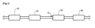
- FIG. 1 is a configuration diagram of an exhaust gas after-treatment apparatus in the related art.
- an after-treatment apparatus for exhaust gas generated in a diesel vehicle includes an exhaust gas oxidation catalyst part 10, an exhaust gas filtering part 20, a selective catalyst reducing part 30, an ammonia oxidation catalyst part 40, and the like that are disposed in this order.
- a dosing valve 31 is connected to a front side of a selective catalyst reducing part 30.
- the nitrogen compound reaches the selective catalyst reducing part 30 while the exhaust gas passes through the exhaust gas oxidation catalyst part 10 and the exhaust gas filtering part 20.
- the after-treatment apparatus in the related art has a manner in which the exhaust gas enters the selective catalyst reducing part 30 regardless of a generated amount of the nitrogen compound. That is, there is a problem in that there is no structure which may control an inflow of gas into the selective catalyst reducing part 30 and an operation of the selective catalyst reducing part 30 on the basis of the generated amount of the nitrogen compound.
- the selective catalyst reducing part 30 is continuously operated regardless of the generated amount of nitrogen compound even if the generated amount of nitrogen compound is small or there is no nitrogen compound, which causes a problem with deterioration in durability.
- ammonia oxidation catalyst part 40 a location to which the nitrogen compound passing through the selective catalyst reducing part 30 flows is the ammonia oxidation catalyst part 40.
- the ammonia oxidation catalyst part 40 is a location where the ammonia is input and reacts with the nitrogen compound.
- the ammonia oxidation catalyst part 40 is operated regardless of a rate of change of the nitrogen compound such that a problem with durability may occur, and this problem occurs because no detecting and calculating means, which may detect the nitrogen compound, is provided at a front side of the ammonia oxidation catalyst part 40.
- an object of the present disclosure is to provide an exhaust gas after-treatment apparatus having improved durability and an exhaust gas after-treatment method in which a detection means and a bypass valve are mounted at front sides of a selective catalyst reducing part and an ammonia oxidation catalyst part so that determination to operate the selective catalyst reducing part and the ammonia oxidation catalyst part may be selectively performed on the basis of a generated amount and a rate of change of nitrogen compound.
- an exhaust gas after-treatment apparatus having improved durability, which includes an exhaust gas oxidation catalyst part which oxidizes exhaust gas; an exhaust gas filtering part which is connected to the exhaust gas oxidation catalyst part, and filters the exhaust gas; a selective catalyst reducing part which is connected to the exhaust gas filtering part; and an ammonia oxidation catalyst part which is connected to the selective catalyst reducing part, in which a first gas detection sensor for detecting a generated amount of nitrogen compound in the exhaust gas flowing from the exhaust gas filtering part, and a selective catalyst reducing bypass valve for selectively blocking the exhaust gas from flowing into the selective catalyst reducing part are installed at a front side of the selective catalyst reducing part, and the exhaust gas after-treatment apparatus includes a control part which is electrically connected so as to control whether to operate the selective catalyst reducing bypass valve and the selective catalyst reducing part on the basis of a gas amount detection signal.
- a second gas detection sensor for detecting nitrogen compound gas, and an ammonia oxidation catalyst bypass valve for selectively blocking the exhaust gas from flowing into the ammonia oxidation catalyst part may be further electrically connected and installed to the control part at a front side of the ammonia oxidation catalyst part.
- an exhaust gas after-treatment method including: detecting, by a first gas detection sensor, a nitrogen compound from exhaust gas passing through an exhaust gas oxidation catalyst part and an exhaust gas filtering part (S100); determining, by a control part, to open and close a selective catalyst reducing bypass valve on the basis of a detection signal (S200); detecting, by a second gas detection sensor, nitrogen compound gas passing through the selective catalyst reducing part (S300); and determining to open and close an ammonia oxidation catalyst bypass valve depending on a calculation of a rate of change of the nitrogen compound of the control part on the basis of the detection signal (S400).
- the exhaust gas after-treatment apparatus having improved durability according to the present disclosure, when a generated amount of nitrogen compound is detected before the exhaust gas flows into the selective catalyst reducing part, and is smaller than a reference value, it is possible to remarkably improve durability of the selective catalyst reducing part by discharging the exhaust gas without allowing the exhaust gas to flow into the selective catalyst reducing part.
- a structure for measuring a rate of change of the nitrogen compound is provided, and thus an inflow of the exhaust gas into the ammonia oxidation catalyst part may be selectively opened and closed, thereby improving durability of the ammonia oxidation catalyst part.
- FIG. 2 is a configuration diagram of an exhaust gas after-treatment apparatus having improved durability according to the present disclosure.
- an exhaust gas after-treatment apparatus having improved durability according to the present disclosure serves to after-treat and discharge exhaust gas of a vehicle, and particularly, includes: gas detection sensors 320 and 420 and bypass valves 330 and 410 which are provided to adjust an inflow of the exhaust gas into a selective catalyst reducing part 300 and an ammonia oxidation catalyst part 400 on the basis of a generated amount and a rate of change of a nitrogen compound; and a control part 500 which controls the gas detection sensors 320 and 420 and the bypass valves 330 and 410.
- the exhaust gas after-treatment apparatus includes an exhaust gas oxidation catalyst part 100 which oxidizes the exhaust gas, and an exhaust gas filtering part 200 which is connected to the exhaust gas oxidation catalyst part 100 and filters the exhaust gas, a selective catalyst reducing part 300 which is connected to the exhaust gas filtering part 200, and has a dosing valve 310 installed at a front side of the selective catalyst reducing part 300, and an ammonia oxidation catalyst part 400 which is connected to the selective catalyst reducing part 300.
- the exhaust gas passing through the exhaust gas oxidation catalyst part 100 and the exhaust gas filtering part 200 flows into the selective catalyst reducing part 300, and when a nitrogen compound is generated from the exhaust gas, the nitrogen compound is decomposed while passing through the selective catalyst reducing part 300, and when a small amount of nitrogen compound is generated or no nitrogen compound is generated, the process in which the exhaust gas flows into the selective catalyst reducing part 300 and the nitrogen compound is decomposed is not necessary.
- a structure which detects a generated amount of nitrogen compound and discharges the nitrogen compound to the outside when the generated amount is smaller than a reference value, is provided at the front side of the selective catalyst reducing part 300, and the structure has a first gas detection sensor 320 and a selective catalyst reducing bypass valve 330.
- a control part 500 is electrically connected to the first gas detection sensor 320 and the selective catalyst reducing bypass valve 330, and the reference value regarding the generated amount of nitrogen compound is stored in the control part 500.
- the control part 500 has an ECU logic calculation structure which determines to open and close the selective catalyst reducing bypass valve 330 through a comparative calculation with the reference value.
- the control part 500 performs the comparative calculation with the stored reference value, and when the generated amount is greater than the reference value, commands the selective catalyst reducing bypass valve 330 to be opened so as to control the corresponding nitrogen compound to pass through the selective catalyst reducing part 300.
- the control part 500 commands the selective catalyst reducing bypass valve 330 to be closed so as to allow the corresponding nitrogen compound to be discharged into the atmosphere, such that it is possible to provide a structure which determines to open and close the selective catalyst reducing bypass valve 330 and to allow the nitrogen compound to flow into the selective catalyst reducing part 300 on the basis of the generated amount of nitrogen compound.
- ammonia oxidation catalyst part 400 is connected to a rear side of the selective catalyst reducing part 300.
- a second gas detection sensor 420 and an ammonia oxidation catalyst bypass valve 410 are installed at a front side of the ammonia oxidation catalyst part 400.
- the second gas detection sensor 420 and the ammonia oxidation catalyst bypass valve 410 are structures that are provided so that determination to allow the nitrogen compound to flow into the ammonia oxidation catalyst part 400 is performed depending on a rate of change of the nitrogen compound, and both the second gas detection sensor 420 and the ammonia oxidation catalyst bypass valve 410 are electrically connected to the control part 500.
- control part 500 stores a reference value regarding the rate of change of the nitrogen compound, and may have a structure, which determines to open and close the ammonia oxidation catalyst bypass valve 410 and to allow the nitrogen compound to flow into the ammonia oxidation catalyst part 400 depending on percentage calculation processing in which values after and before a change of the nitrogen compound are divided by a value before the change of the nitrogen compound, and depending on a comparative calculation with the reference value.
- factor variables which are multiplied depending on a temperature of an engine and atmospheric pressure in order to correct a result of the calculation processing, may be used to perform the calculation of the control part 500, and relevant optimal values may be obtained by reflecting test result values.
- the nitrogen compound as corresponding nitrogen compound gas is detected by the second gas detection sensor 420, and the detection signal is sent to the control part 500.
- the control part 500 opens the ammonia oxidation catalyst bypass valve 410 so that the nitrogen compound flows into the ammonia oxidation catalyst part 400 and then is decomposed, and in a case in which the generated amount of nitrogen compound is the reference value or less, the control part 500 commands the ammonia oxidation catalyst bypass valve 410 to be closed so that the nitrogen compound, which has an amount equal to or smaller than the reference value, is discharged into the atmosphere, such that it is possible to implement a structure in which determination to allow the nitrogen compound to flow into the ammonia oxidation catalyst part 400 may be performed by the comparison with the reference value set to the control part.
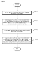
- FIG. 3 is a flowchart regarding an exhaust gas after-treatment method according to the present disclosure.
- an exhaust gas after-treatment method of the present disclosure is a process which is configured to perform selective catalytic reduction and an operation of an ammonia oxidation catalyst on the basis of the generated amount and the rate of change of the nitrogen compound generated in the exhaust gas.
- the generated amount of exhaust gas nitrogen compound is detected before the exhaust gas discharged from the vehicle flows into the selective catalyst reducing part 300 from the exhaust gas oxidation catalyst part 100 and the exhaust gas filtering part 200 (S100).
- the generated amount of nitrogen compound is detected by the first gas detection sensor 320 installed at the front side of the selective catalyst reducing part 300.
- control part 500 performs comparative calculation processing with the reference value on the basis of the detection signal of the nitrogen compound, and determines to open and close the selective catalyst reducing bypass valve 330 with respect to the selective catalyst reducing part 300 depending on the corresponding result.
- the control part 500 compares the detection signal of the first gas detection sensor 320 with the stored reference value, and opens the selective catalyst reducing bypass valve 330 when the detection signal is greater than the reference value, so as to allow the corresponding nitrogen compound to flow into the selective catalyst reducing part 300.
- control part 500 closes the selective catalyst reducing bypass valve 330 so as to allow the nitrogen compound to be discharged into the atmosphere (S200).
- the second gas detection sensor 420 detects the nitrogen compound gas passing through the selective catalyst reducing part 300, and sends the corresponding detection signal to the control part 500.
- the second gas detection sensor 420 is installed at the front side of the ammonia oxidation catalyst part 400 together with the ammonia oxidation catalyst bypass valve 410.
- the nitrogen compound gas may be detected by the second gas detection sensor 420 (S300)
- control part 500 has an ECU logic manner and stores a calculation formula of (a value before change - a value after change) / a value before change ⁇ 100 together with the reference value regarding a rate of change, and a temperature of the engine and the atmospheric pressure at the corresponding time as corrected values, and a next step is a step of measuring the rate of change of the corresponding nitrogen compound on the basis of the detection signal of the second gas detection sensor 420, and determining to open and close the ammonia oxidation catalyst bypass valve 410 by comparing the detection signal with the reference value.
- the control part 500 stores the reference value regarding the rate of change of the nitrogen compound, and compares the calculated rate of change and the reference value on the basis of the corresponding detection signal. In this case, when the rate of change is higher than the reference value, the control part 500 commands the ammonia oxidation catalyst bypass valve 410 to be opened so as to allow the corresponding nitrogen compound to flow into the ammonia oxidation catalyst part 410, and when the rate of change is the reference value or less, the control part 500 commands the ammonia oxidation catalyst bypass valve 410 to be closed to allow the nitrogen compound to be discharged into the atmosphere (S400).
- the processes of the after-treatment method according to the present disclosure it is possible to determine to perform a selective catalyst reducing reaction or an ammonia oxidation catalyst reaction of the nitrogen compound on the basis of the generated amount and the rate of change of the nitrogen compound.
- the present disclosure may be used to purify nitrogen oxide included in exhaust gas using selective catalytic reduction (SCR).
- SCR selective catalytic reduction
Landscapes
- Engineering & Computer Science (AREA)
- Chemical & Material Sciences (AREA)
- Chemical Kinetics & Catalysis (AREA)
- Health & Medical Sciences (AREA)
- Combustion & Propulsion (AREA)
- Environmental & Geological Engineering (AREA)
- Mechanical Engineering (AREA)
- General Engineering & Computer Science (AREA)
- Biomedical Technology (AREA)
- Analytical Chemistry (AREA)
- General Chemical & Material Sciences (AREA)
- Oil, Petroleum & Natural Gas (AREA)
- Toxicology (AREA)
- Materials Engineering (AREA)
- Exhaust Gas After Treatment (AREA)
- Exhaust Gas Treatment By Means Of Catalyst (AREA)
Abstract
Description
- The present disclosure relates to an exhaust gas after-treatment apparatus and an exhaust gas after-treatment method including a selective catalytic reduction (SCR) process, and more particularly, to an exhaust gas after-treatment apparatus having improved durability and an exhaust gas after-treatment method, which selectively determine to operate a selective catalyst reducing part and an ammonia oxidation catalyst (AOC) part on the basis of a generated amount and a rate of change of a nitrogen compound (NOx) in exhaust gas.
-
FIG. 1 is a configuration diagram of an exhaust gas after-treatment apparatus in the related art. In general, as illustrated inFIG. 1 , an after-treatment apparatus for exhaust gas generated in a diesel vehicle includes an exhaust gasoxidation catalyst part 10, an exhaust gas filteringpart 20, a selectivecatalyst reducing part 30, an ammoniaoxidation catalyst part 40, and the like that are disposed in this order. - Here, a
dosing valve 31 is connected to a front side of a selectivecatalyst reducing part 30. - In the after-treatment apparatus and a process of using the after-treatment apparatus in the related art, the nitrogen compound reaches the selective
catalyst reducing part 30 while the exhaust gas passes through the exhaust gasoxidation catalyst part 10 and the exhaust gas filteringpart 20. - In this case, the after-treatment apparatus in the related art has a manner in which the exhaust gas enters the selective
catalyst reducing part 30 regardless of a generated amount of the nitrogen compound. That is, there is a problem in that there is no structure which may control an inflow of gas into the selectivecatalyst reducing part 30 and an operation of the selectivecatalyst reducing part 30 on the basis of the generated amount of the nitrogen compound. - Accordingly, the selective
catalyst reducing part 30 is continuously operated regardless of the generated amount of nitrogen compound even if the generated amount of nitrogen compound is small or there is no nitrogen compound, which causes a problem with deterioration in durability. - In addition, a location to which the nitrogen compound passing through the selective
catalyst reducing part 30 flows is the ammoniaoxidation catalyst part 40. The ammoniaoxidation catalyst part 40 is a location where the ammonia is input and reacts with the nitrogen compound. - Even in this case, the ammonia
oxidation catalyst part 40 is operated regardless of a rate of change of the nitrogen compound such that a problem with durability may occur, and this problem occurs because no detecting and calculating means, which may detect the nitrogen compound, is provided at a front side of the ammoniaoxidation catalyst part 40. - Therefore, it is urgently needed to develop an apparatus having a structure in which determination to operate the selective
catalyst reducing part 30 and the ammoniaoxidation catalyst part 40 is performed on the basis of the generated amount or the rate of change of nitrogen compound. - Accordingly, the present disclosure has been made in consideration of the aforementioned problem in the related art, and an object of the present disclosure is to provide an exhaust gas after-treatment apparatus having improved durability and an exhaust gas after-treatment method in which a detection means and a bypass valve are mounted at front sides of a selective catalyst reducing part and an ammonia oxidation catalyst part so that determination to operate the selective catalyst reducing part and the ammonia oxidation catalyst part may be selectively performed on the basis of a generated amount and a rate of change of nitrogen compound.
- The aforementioned object of the present disclosure is achieved by an exhaust gas after-treatment apparatus having improved durability, which includes an exhaust gas oxidation catalyst part which oxidizes exhaust gas; an exhaust gas filtering part which is connected to the exhaust gas oxidation catalyst part, and filters the exhaust gas; a selective catalyst reducing part which is connected to the exhaust gas filtering part; and an ammonia oxidation catalyst part which is connected to the selective catalyst reducing part, in which a first gas detection sensor for detecting a generated amount of nitrogen compound in the exhaust gas flowing from the exhaust gas filtering part, and a selective catalyst reducing bypass valve for selectively blocking the exhaust gas from flowing into the selective catalyst reducing part are installed at a front side of the selective catalyst reducing part, and the exhaust gas after-treatment apparatus includes a control part which is electrically connected so as to control whether to operate the selective catalyst reducing bypass valve and the selective catalyst reducing part on the basis of a gas amount detection signal.
- Here, a second gas detection sensor for detecting nitrogen compound gas, and an ammonia oxidation catalyst bypass valve for selectively blocking the exhaust gas from flowing into the ammonia oxidation catalyst part may be further electrically connected and installed to the control part at a front side of the ammonia oxidation catalyst part.
- Meanwhile, the aforementioned object of the present disclosure is achieved by an exhaust gas after-treatment method including: detecting, by a first gas detection sensor, a nitrogen compound from exhaust gas passing through an exhaust gas oxidation catalyst part and an exhaust gas filtering part (S100); determining, by a control part, to open and close a selective catalyst reducing bypass valve on the basis of a detection signal (S200); detecting, by a second gas detection sensor, nitrogen compound gas passing through the selective catalyst reducing part (S300); and determining to open and close an ammonia oxidation catalyst bypass valve depending on a calculation of a rate of change of the nitrogen compound of the control part on the basis of the detection signal (S400).
- According to the exhaust gas after-treatment apparatus having improved durability according to the present disclosure, when a generated amount of nitrogen compound is detected before the exhaust gas flows into the selective catalyst reducing part, and is smaller than a reference value, it is possible to remarkably improve durability of the selective catalyst reducing part by discharging the exhaust gas without allowing the exhaust gas to flow into the selective catalyst reducing part.
- In addition, a structure for measuring a rate of change of the nitrogen compound is provided, and thus an inflow of the exhaust gas into the ammonia oxidation catalyst part may be selectively opened and closed, thereby improving durability of the ammonia oxidation catalyst part.
- Other problems, specific advantages and novel features of the present disclosure will be more clearer through the following detailed description and preferred exemplary embodiments associated with the accompanying drawings.
-
-
FIG. 1 is a configuration diagram of an exhaust gas after-treatment apparatus in the related art. -
FIG. 2 is a configuration diagram of an exhaust gas after-treatment apparatus having improved durability according to the present disclosure. -
FIG. 3 is a flowchart regarding an exhaust gas after-treatment method according to the present disclosure. -
- 10: Exhaust gas oxidation catalyst part
- 20: Exhaust gas filtering part
- 30: Selective catalyst reducing part
- 31: Dosing valve
- 40: Ammonia oxidation catalyst part
- 100: Exhaust gas oxidation catalyst part
- 200: Exhaust gas filtering part
- 300: Selective catalyst reducing part
- 310: Dosing valve
- 320: First gas detection sensor
- 330: Selective catalyst reducing bypass valve
- 400: Ammonia oxidation catalyst part
- 410: Ammonia oxidation catalyst bypass valve
- 420: Second gas detection sensor
- 500: Control part
- Hereinafter, an exhaust gas after-treatment apparatus having improved durability according to the present disclosure will be described with reference to the accompanying drawings.
-
FIG. 2 is a configuration diagram of an exhaust gas after-treatment apparatus having improved durability according to the present disclosure. As illustrated inFIG. 2 , an exhaust gas after-treatment apparatus having improved durability according to the present disclosure serves to after-treat and discharge exhaust gas of a vehicle, and particularly, includes:gas detection sensors bypass valves catalyst reducing part 300 and an ammoniaoxidation catalyst part 400 on the basis of a generated amount and a rate of change of a nitrogen compound; and acontrol part 500 which controls thegas detection sensors bypass valves - The exhaust gas after-treatment apparatus according to the present disclosure includes an exhaust gas
oxidation catalyst part 100 which oxidizes the exhaust gas, and an exhaust gas filteringpart 200 which is connected to the exhaust gasoxidation catalyst part 100 and filters the exhaust gas, a selectivecatalyst reducing part 300 which is connected to the exhaust gas filteringpart 200, and has adosing valve 310 installed at a front side of the selectivecatalyst reducing part 300, and an ammoniaoxidation catalyst part 400 which is connected to the selectivecatalyst reducing part 300. - Here, the exhaust gas passing through the exhaust gas
oxidation catalyst part 100 and the exhaust gas filteringpart 200 flows into the selectivecatalyst reducing part 300, and when a nitrogen compound is generated from the exhaust gas, the nitrogen compound is decomposed while passing through the selectivecatalyst reducing part 300, and when a small amount of nitrogen compound is generated or no nitrogen compound is generated, the process in which the exhaust gas flows into the selectivecatalyst reducing part 300 and the nitrogen compound is decomposed is not necessary. - In the after-treatment apparatus according to the present disclosure, a structure, which detects a generated amount of nitrogen compound and discharges the nitrogen compound to the outside when the generated amount is smaller than a reference value, is provided at the front side of the selective
catalyst reducing part 300, and the structure has a firstgas detection sensor 320 and a selective catalyst reducingbypass valve 330. - In addition, a
control part 500 is electrically connected to the firstgas detection sensor 320 and the selective catalyst reducingbypass valve 330, and the reference value regarding the generated amount of nitrogen compound is stored in thecontrol part 500. - The
control part 500 has an ECU logic calculation structure which determines to open and close the selective catalyst reducingbypass valve 330 through a comparative calculation with the reference value. - Therefore, in a case in which the first
gas detection sensor 320 detects the nitrogen compound, and sends the detection signal to thecontrol part 500, thecontrol part 500 performs the comparative calculation with the stored reference value, and when the generated amount is greater than the reference value, commands the selective catalyst reducingbypass valve 330 to be opened so as to control the corresponding nitrogen compound to pass through the selectivecatalyst reducing part 300. - On the contrary, when the generated amount is the reference value or less, the
control part 500 commands the selective catalyst reducingbypass valve 330 to be closed so as to allow the corresponding nitrogen compound to be discharged into the atmosphere, such that it is possible to provide a structure which determines to open and close the selective catalyst reducingbypass valve 330 and to allow the nitrogen compound to flow into the selectivecatalyst reducing part 300 on the basis of the generated amount of nitrogen compound. - In addition, the ammonia
oxidation catalyst part 400 is connected to a rear side of the selectivecatalyst reducing part 300. A secondgas detection sensor 420 and an ammonia oxidationcatalyst bypass valve 410 are installed at a front side of the ammoniaoxidation catalyst part 400. - The second
gas detection sensor 420 and the ammonia oxidationcatalyst bypass valve 410 are structures that are provided so that determination to allow the nitrogen compound to flow into the ammoniaoxidation catalyst part 400 is performed depending on a rate of change of the nitrogen compound, and both the secondgas detection sensor 420 and the ammonia oxidationcatalyst bypass valve 410 are electrically connected to thecontrol part 500. - In this case, the
control part 500 stores a reference value regarding the rate of change of the nitrogen compound, and may have a structure, which determines to open and close the ammonia oxidationcatalyst bypass valve 410 and to allow the nitrogen compound to flow into the ammoniaoxidation catalyst part 400 depending on percentage calculation processing in which values after and before a change of the nitrogen compound are divided by a value before the change of the nitrogen compound, and depending on a comparative calculation with the reference value. - In this case, factor variables, which are multiplied depending on a temperature of an engine and atmospheric pressure in order to correct a result of the calculation processing, may be used to perform the calculation of the
control part 500, and relevant optimal values may be obtained by reflecting test result values. - Therefore, in a case in which the nitrogen compound flows into the ammonia
oxidation catalyst part 400, the nitrogen compound as corresponding nitrogen compound gas is detected by the secondgas detection sensor 420, and the detection signal is sent to thecontrol part 500. - Then, through the aforementioned calculation processing and the comparison with the reference value on the basis of the detection signal, in a case in which the generated amount of nitrogen compound is greater than the reference value, the
control part 500 opens the ammonia oxidationcatalyst bypass valve 410 so that the nitrogen compound flows into the ammoniaoxidation catalyst part 400 and then is decomposed, and in a case in which the generated amount of nitrogen compound is the reference value or less, thecontrol part 500 commands the ammonia oxidationcatalyst bypass valve 410 to be closed so that the nitrogen compound, which has an amount equal to or smaller than the reference value, is discharged into the atmosphere, such that it is possible to implement a structure in which determination to allow the nitrogen compound to flow into the ammoniaoxidation catalyst part 400 may be performed by the comparison with the reference value set to the control part. -
FIG. 3 is a flowchart regarding an exhaust gas after-treatment method according to the present disclosure. As illustrated inFIG. 3 , an exhaust gas after-treatment method of the present disclosure is a process which is configured to perform selective catalytic reduction and an operation of an ammonia oxidation catalyst on the basis of the generated amount and the rate of change of the nitrogen compound generated in the exhaust gas. - First, the generated amount of exhaust gas nitrogen compound is detected before the exhaust gas discharged from the vehicle flows into the selective
catalyst reducing part 300 from the exhaust gasoxidation catalyst part 100 and the exhaust gas filtering part 200 (S100). - In this case, the generated amount of nitrogen compound is detected by the first
gas detection sensor 320 installed at the front side of the selectivecatalyst reducing part 300. - Next, the
control part 500 performs comparative calculation processing with the reference value on the basis of the detection signal of the nitrogen compound, and determines to open and close the selective catalyst reducingbypass valve 330 with respect to the selectivecatalyst reducing part 300 depending on the corresponding result. - The
control part 500 compares the detection signal of the firstgas detection sensor 320 with the stored reference value, and opens the selective catalyst reducingbypass valve 330 when the detection signal is greater than the reference value, so as to allow the corresponding nitrogen compound to flow into the selectivecatalyst reducing part 300. - On the contrary, when the corresponding detection signal is the reference value or less, the
control part 500 closes the selective catalyst reducingbypass valve 330 so as to allow the nitrogen compound to be discharged into the atmosphere (S200). - In a next step of detecting an inflow of nitrogen compound gas when the nitrogen compound gas of the selective
catalyst reducing part 300 flows into the ammoniaoxidation catalyst part 400, the secondgas detection sensor 420 detects the nitrogen compound gas passing through the selectivecatalyst reducing part 300, and sends the corresponding detection signal to thecontrol part 500. - The second
gas detection sensor 420 is installed at the front side of the ammoniaoxidation catalyst part 400 together with the ammonia oxidationcatalyst bypass valve 410. - Therefore, in a case in which the nitrogen compound reaches the ammonia
oxidation catalyst part 400, the nitrogen compound gas may be detected by the second gas detection sensor 420 (S300) - In this case, the
control part 500 has an ECU logic manner and stores a calculation formula of (a value before change - a value after change) / a value before change × 100 together with the reference value regarding a rate of change, and a temperature of the engine and the atmospheric pressure at the corresponding time as corrected values, and a next step is a step of measuring the rate of change of the corresponding nitrogen compound on the basis of the detection signal of the secondgas detection sensor 420, and determining to open and close the ammonia oxidationcatalyst bypass valve 410 by comparing the detection signal with the reference value. - The
control part 500 stores the reference value regarding the rate of change of the nitrogen compound, and compares the calculated rate of change and the reference value on the basis of the corresponding detection signal. In this case, when the rate of change is higher than the reference value, thecontrol part 500 commands the ammonia oxidationcatalyst bypass valve 410 to be opened so as to allow the corresponding nitrogen compound to flow into the ammoniaoxidation catalyst part 410, and when the rate of change is the reference value or less, thecontrol part 500 commands the ammonia oxidationcatalyst bypass valve 410 to be closed to allow the nitrogen compound to be discharged into the atmosphere (S400). - According to the processes of the after-treatment method according to the present disclosure, it is possible to determine to perform a selective catalyst reducing reaction or an ammonia oxidation catalyst reaction of the nitrogen compound on the basis of the generated amount and the rate of change of the nitrogen compound.
- The present disclosure may be used to purify nitrogen oxide included in exhaust gas using selective catalytic reduction (SCR).
Claims (3)
- An exhaust gas after-treatment apparatus having improved durability, comprising:an exhaust gas oxidation catalyst part 100 which oxidizes exhaust gas;an exhaust gas filtering part 200 which is connected to the exhaust gas oxidation catalyst part 100, and filters the exhaust gas;a selective catalyst reducing part 300 which is connected to the exhaust gas filtering part 200; andan ammonia oxidation catalyst part 400 which is connected to the selective catalyst reducing part 300,wherein a first gas detection sensor 320 for detecting a generated amount of nitrogen compound in the exhaust gas flowing from the exhaust gas filtering part 200, and a selective catalyst reducing bypass valve 330 for selectively blocking the exhaust gas from flowing into the selective catalyst reducing part 300 are installed at a front side of the selective catalyst reducing part 300, and the exhaust gas after-treatment apparatus includes a control part 500 which is electrically connected so as to control whether to operate the selective catalyst reducing bypass valve 330 and the selective catalyst reducing part 300 on the basis of a gas amount detection signal.
- The exhaust gas after-treatment apparatus of claim 1, wherein a second gas detection sensor 420 for detecting nitrogen compound gas, and an ammonia oxidation catalyst bypass valve 410 for selectively blocking the exhaust gas from flowing into the ammonia oxidation catalyst part 400 are further electrically connected and installed to the control part 500 at a front side of the ammonia oxidation catalyst part 400.
- An exhaust gas after-treatment method comprising:detecting, by a first gas detection sensor 320, a nitrogen compound from exhaust gas passing through an exhaust gas oxidation catalyst part 100 and an exhaust gas filtering part 200 (S100);determining, by a control part 500, to open and close a selective catalyst reducing bypass valve 330 with respect to a selective catalyst reducing part 300 on the basis of a detection signal (S200);detecting, by a second gas detection sensor 420, nitrogen compound gas passing through the selective catalyst reducing bypass valve 300 (S300); anddetermining to open and close an ammonia oxidation catalyst bypass valve 410 with respect to an ammonia oxidation catalyst part 400 depending on a calculation of a rate of change of the nitrogen compound of the control part 500 on the basis of the detection signal (S400).
Applications Claiming Priority (2)
| Application Number | Priority Date | Filing Date | Title |
|---|---|---|---|
| KR1020110143279A KR101840475B1 (en) | 2011-12-27 | 2011-12-27 | An after treatment device with a structure of improved durability and method thereof |
| PCT/KR2012/010984 WO2013100460A1 (en) | 2011-12-27 | 2012-12-17 | Exhaust gas after-treatment apparatus having improved durability and exhaust gas after-treatment method |
Publications (3)
| Publication Number | Publication Date |
|---|---|
| EP2799678A1 true EP2799678A1 (en) | 2014-11-05 |
| EP2799678A4 EP2799678A4 (en) | 2015-08-19 |
| EP2799678B1 EP2799678B1 (en) | 2018-08-29 |
Family
ID=48697842
Family Applications (1)
| Application Number | Title | Priority Date | Filing Date |
|---|---|---|---|
| EP12861341.1A Not-in-force EP2799678B1 (en) | 2011-12-27 | 2012-12-17 | Exhaust gas after-treatment apparatus having improved durability |
Country Status (5)
| Country | Link |
|---|---|
| US (1) | US9346014B2 (en) |
| EP (1) | EP2799678B1 (en) |
| KR (1) | KR101840475B1 (en) |
| CN (1) | CN104024595B (en) |
| WO (1) | WO2013100460A1 (en) |
Cited By (1)
| Publication number | Priority date | Publication date | Assignee | Title |
|---|---|---|---|---|
| FR3054600A1 (en) * | 2016-08-01 | 2018-02-02 | Peugeot Citroen Automobiles Sa | METHOD FOR PROTECTING A CATALYST FOR TREATING AMMONIA RELEASES IN AN EXHAUST LINE |
Families Citing this family (2)
| Publication number | Priority date | Publication date | Assignee | Title |
|---|---|---|---|---|
| JP2019094851A (en) * | 2017-11-24 | 2019-06-20 | スズキ株式会社 | Arrangement structure of exhaust gas sensor and exhaust control system |
| CN112742157A (en) * | 2020-12-11 | 2021-05-04 | 九江鑫星绝缘材料有限公司 | Exhaust treatment mechanism of adhesive tape dipping equipment |
Family Cites Families (12)
| Publication number | Priority date | Publication date | Assignee | Title |
|---|---|---|---|---|
| DE19855384A1 (en) * | 1998-12-01 | 2000-06-08 | Bosch Gmbh Robert | Device for the aftertreatment of exhaust gases from an internal combustion engine |
| JP4290037B2 (en) | 2004-03-02 | 2009-07-01 | 日産ディーゼル工業株式会社 | Engine exhaust purification system |
| JP2006046288A (en) * | 2004-08-09 | 2006-02-16 | Hino Motors Ltd | Exhaust purification device |
| JP2006207512A (en) | 2005-01-31 | 2006-08-10 | Bosch Corp | Exhaust emission control device and exhaust emission control method for internal combustion engine |
| JP2007100508A (en) | 2005-09-30 | 2007-04-19 | Bosch Corp | Exhaust emission control device of internal combustion engine, and exhaust emission control method for internal combustion engine |
| US7810316B2 (en) | 2006-12-29 | 2010-10-12 | Cummins Filtration Ip, Inc | Apparatus, system, and method for exhaust aftertreatment efficiency enhancement |
| US20100199634A1 (en) | 2007-05-02 | 2010-08-12 | David Mark Heaton | Exhaust treatment system implementing selective doc bypass |
| JP4788664B2 (en) | 2007-06-08 | 2011-10-05 | トヨタ自動車株式会社 | Exhaust gas purification system for internal combustion engine |
| US20090199537A1 (en) | 2008-02-11 | 2009-08-13 | Detroit Diesel Corporation | Methods to protect selective catalyst reducer aftertreatment devices during uncontrolled diesel particulate filter regeneration |
| WO2010032738A1 (en) | 2008-09-17 | 2010-03-25 | ヤンマー株式会社 | Exhaust gas purifying device |
| US10145283B2 (en) | 2009-03-05 | 2018-12-04 | Volvo Lastvagnar Ab | Diesel engine system and method and apparatus for handling diesel engine exhaust |
| US9038373B2 (en) | 2010-05-03 | 2015-05-26 | Cummins Inc. | Ammonia sensor control of an SCR aftertreatment system |
-
2011
- 2011-12-27 KR KR1020110143279A patent/KR101840475B1/en not_active Expired - Fee Related
-
2012
- 2012-12-17 US US14/369,578 patent/US9346014B2/en not_active Expired - Fee Related
- 2012-12-17 CN CN201280065220.1A patent/CN104024595B/en not_active Expired - Fee Related
- 2012-12-17 WO PCT/KR2012/010984 patent/WO2013100460A1/en not_active Ceased
- 2012-12-17 EP EP12861341.1A patent/EP2799678B1/en not_active Not-in-force
Cited By (1)
| Publication number | Priority date | Publication date | Assignee | Title |
|---|---|---|---|---|
| FR3054600A1 (en) * | 2016-08-01 | 2018-02-02 | Peugeot Citroen Automobiles Sa | METHOD FOR PROTECTING A CATALYST FOR TREATING AMMONIA RELEASES IN AN EXHAUST LINE |
Also Published As
| Publication number | Publication date |
|---|---|
| US20150004085A1 (en) | 2015-01-01 |
| KR101840475B1 (en) | 2018-03-21 |
| CN104024595B (en) | 2016-08-24 |
| WO2013100460A1 (en) | 2013-07-04 |
| KR20130075079A (en) | 2013-07-05 |
| CN104024595A (en) | 2014-09-03 |
| EP2799678B1 (en) | 2018-08-29 |
| US9346014B2 (en) | 2016-05-24 |
| EP2799678A4 (en) | 2015-08-19 |
Similar Documents
| Publication | Publication Date | Title |
|---|---|---|
| EP1811144B1 (en) | Exhaust gas purification apparatus | |
| CN105579679B (en) | Abnormality diagnosis device of exhaust purification system | |
| CN103703222B (en) | The quality containing ammonia reductant solution that is used for reducing nitrogen oxide is carried out to definite method | |
| EP2037090B1 (en) | Particulate filter failure detecting system | |
| EP3012426B1 (en) | Diagnostic device for urea water supply system | |
| EP3085909B1 (en) | Exhaust control system for internal combustion engine | |
| JP5170689B2 (en) | Exhaust gas purification device for internal combustion engine | |
| EP2278144A1 (en) | NOx SENSOR ABNORMALITY DIAGNOSING APPARATUS AND ABNORMALITY DIAGNOSING METHOD | |
| EP2915969B1 (en) | Exhaust purification device and exhaust purification method for internal combustion engine | |
| CN105579678A (en) | Sensor Abnormality Diagnosis Device | |
| US8091343B2 (en) | Exhaust gas purification apparatus for internal combustion engine | |
| CN101668931A (en) | Apparatus for diagnosis of abnormality in exhaust gas purification system | |
| US8490386B2 (en) | Method for detecting abnormality in reducing agent | |
| CN105579677A (en) | Diagnostic device for exhaust-gas purification device | |
| US20100175368A1 (en) | Method for checking an oxidation catalytic converter and exhaust gas after treatment arrangement for an internal combustion engine | |
| US10634032B2 (en) | Method and apparatus for monitoring an exhaust aftertreatment system for an internal combustion engine | |
| CN102817684B (en) | The diagnostic method of filter and diagnostic module for gas extraction system NOx sensor | |
| EP2843205A1 (en) | System for determining abnormality in exhaust emission control device for internal combustion engine | |
| EP2799678B1 (en) | Exhaust gas after-treatment apparatus having improved durability | |
| CN107131041A (en) | For the method for the exhausted gas post-processing system for diagnosing internal combustion engine | |
| JP5240065B2 (en) | Failure detection device for exhaust gas purification device | |
| US20210063270A1 (en) | Method of estimating oxygen storage capacity of catalyst | |
| CN104727913B (en) | Determine the method and system of the adaptability of the correction to the control logic of catalyst converter | |
| US8380353B2 (en) | Method for calculating loading amount of ammonia in selective catalytic reduction apparatus | |
| US12203398B2 (en) | Method and device for determining the sulphur content in an exhaust gas channel of a motor vehicle in relation to the supplied fuel |
Legal Events
| Date | Code | Title | Description |
|---|---|---|---|
| PUAI | Public reference made under article 153(3) epc to a published international application that has entered the european phase |
Free format text: ORIGINAL CODE: 0009012 |
|
| 17P | Request for examination filed |
Effective date: 20140707 |
|
| AK | Designated contracting states |
Kind code of ref document: A1 Designated state(s): AL AT BE BG CH CY CZ DE DK EE ES FI FR GB GR HR HU IE IS IT LI LT LU LV MC MK MT NL NO PL PT RO RS SE SI SK SM TR |
|
| RIN1 | Information on inventor provided before grant (corrected) |
Inventor name: LIM, JI HOON Inventor name: KO, MINSEOK Inventor name: OH, BYOUNGGUL Inventor name: PARK, KYUNGMIN Inventor name: KIM, SANGHOON |
|
| DAX | Request for extension of the european patent (deleted) | ||
| RA4 | Supplementary search report drawn up and despatched (corrected) |
Effective date: 20150720 |
|
| RIC1 | Information provided on ipc code assigned before grant |
Ipc: F01N 3/20 20060101AFI20150714BHEP Ipc: B01D 53/94 20060101ALI20150714BHEP Ipc: F01N 3/035 20060101ALI20150714BHEP |
|
| 17Q | First examination report despatched |
Effective date: 20161010 |
|
| STAA | Information on the status of an ep patent application or granted ep patent |
Free format text: STATUS: EXAMINATION IS IN PROGRESS |
|
| REG | Reference to a national code |
Ref country code: DE Ref legal event code: R079 Ref document number: 602012050505 Country of ref document: DE Free format text: PREVIOUS MAIN CLASS: F01N0003200000 Ipc: F01N0003100000 |
|
| GRAP | Despatch of communication of intention to grant a patent |
Free format text: ORIGINAL CODE: EPIDOSNIGR1 |
|
| STAA | Information on the status of an ep patent application or granted ep patent |
Free format text: STATUS: GRANT OF PATENT IS INTENDED |
|
| RIC1 | Information provided on ipc code assigned before grant |
Ipc: F01N 11/00 20060101ALI20180220BHEP Ipc: F01N 3/20 20060101ALI20180220BHEP Ipc: F01N 3/023 20060101ALI20180220BHEP Ipc: B01D 53/94 20060101ALI20180220BHEP Ipc: F01N 3/10 20060101AFI20180220BHEP |
|
| INTG | Intention to grant announced |
Effective date: 20180323 |
|
| GRAS | Grant fee paid |
Free format text: ORIGINAL CODE: EPIDOSNIGR3 |
|
| GRAA | (expected) grant |
Free format text: ORIGINAL CODE: 0009210 |
|
| STAA | Information on the status of an ep patent application or granted ep patent |
Free format text: STATUS: THE PATENT HAS BEEN GRANTED |
|
| AK | Designated contracting states |
Kind code of ref document: B1 Designated state(s): AL AT BE BG CH CY CZ DE DK EE ES FI FR GB GR HR HU IE IS IT LI LT LU LV MC MK MT NL NO PL PT RO RS SE SI SK SM TR |
|
| REG | Reference to a national code |
Ref country code: GB Ref legal event code: FG4D |
|
| REG | Reference to a national code |
Ref country code: CH Ref legal event code: EP |
|
| REG | Reference to a national code |
Ref country code: AT Ref legal event code: REF Ref document number: 1035377 Country of ref document: AT Kind code of ref document: T Effective date: 20180915 |
|
| REG | Reference to a national code |
Ref country code: IE Ref legal event code: FG4D |
|
| REG | Reference to a national code |
Ref country code: DE Ref legal event code: R096 Ref document number: 602012050505 Country of ref document: DE |
|
| REG | Reference to a national code |
Ref country code: NL Ref legal event code: MP Effective date: 20180829 |
|
| REG | Reference to a national code |
Ref country code: LT Ref legal event code: MG4D |
|
| PG25 | Lapsed in a contracting state [announced via postgrant information from national office to epo] |
Ref country code: NO Free format text: LAPSE BECAUSE OF FAILURE TO SUBMIT A TRANSLATION OF THE DESCRIPTION OR TO PAY THE FEE WITHIN THE PRESCRIBED TIME-LIMIT Effective date: 20181129 Ref country code: BG Free format text: LAPSE BECAUSE OF FAILURE TO SUBMIT A TRANSLATION OF THE DESCRIPTION OR TO PAY THE FEE WITHIN THE PRESCRIBED TIME-LIMIT Effective date: 20181129 Ref country code: SE Free format text: LAPSE BECAUSE OF FAILURE TO SUBMIT A TRANSLATION OF THE DESCRIPTION OR TO PAY THE FEE WITHIN THE PRESCRIBED TIME-LIMIT Effective date: 20180829 Ref country code: IS Free format text: LAPSE BECAUSE OF FAILURE TO SUBMIT A TRANSLATION OF THE DESCRIPTION OR TO PAY THE FEE WITHIN THE PRESCRIBED TIME-LIMIT Effective date: 20181229 Ref country code: LT Free format text: LAPSE BECAUSE OF FAILURE TO SUBMIT A TRANSLATION OF THE DESCRIPTION OR TO PAY THE FEE WITHIN THE PRESCRIBED TIME-LIMIT Effective date: 20180829 Ref country code: GR Free format text: LAPSE BECAUSE OF FAILURE TO SUBMIT A TRANSLATION OF THE DESCRIPTION OR TO PAY THE FEE WITHIN THE PRESCRIBED TIME-LIMIT Effective date: 20181130 Ref country code: NL Free format text: LAPSE BECAUSE OF FAILURE TO SUBMIT A TRANSLATION OF THE DESCRIPTION OR TO PAY THE FEE WITHIN THE PRESCRIBED TIME-LIMIT Effective date: 20180829 Ref country code: RS Free format text: LAPSE BECAUSE OF FAILURE TO SUBMIT A TRANSLATION OF THE DESCRIPTION OR TO PAY THE FEE WITHIN THE PRESCRIBED TIME-LIMIT Effective date: 20180829 Ref country code: FI Free format text: LAPSE BECAUSE OF FAILURE TO SUBMIT A TRANSLATION OF THE DESCRIPTION OR TO PAY THE FEE WITHIN THE PRESCRIBED TIME-LIMIT Effective date: 20180829 |
|
| REG | Reference to a national code |
Ref country code: AT Ref legal event code: MK05 Ref document number: 1035377 Country of ref document: AT Kind code of ref document: T Effective date: 20180829 |
|
| PG25 | Lapsed in a contracting state [announced via postgrant information from national office to epo] |
Ref country code: AL Free format text: LAPSE BECAUSE OF FAILURE TO SUBMIT A TRANSLATION OF THE DESCRIPTION OR TO PAY THE FEE WITHIN THE PRESCRIBED TIME-LIMIT Effective date: 20180829 Ref country code: HR Free format text: LAPSE BECAUSE OF FAILURE TO SUBMIT A TRANSLATION OF THE DESCRIPTION OR TO PAY THE FEE WITHIN THE PRESCRIBED TIME-LIMIT Effective date: 20180829 Ref country code: LV Free format text: LAPSE BECAUSE OF FAILURE TO SUBMIT A TRANSLATION OF THE DESCRIPTION OR TO PAY THE FEE WITHIN THE PRESCRIBED TIME-LIMIT Effective date: 20180829 |
|
| PG25 | Lapsed in a contracting state [announced via postgrant information from national office to epo] |
Ref country code: EE Free format text: LAPSE BECAUSE OF FAILURE TO SUBMIT A TRANSLATION OF THE DESCRIPTION OR TO PAY THE FEE WITHIN THE PRESCRIBED TIME-LIMIT Effective date: 20180829 Ref country code: AT Free format text: LAPSE BECAUSE OF FAILURE TO SUBMIT A TRANSLATION OF THE DESCRIPTION OR TO PAY THE FEE WITHIN THE PRESCRIBED TIME-LIMIT Effective date: 20180829 Ref country code: IT Free format text: LAPSE BECAUSE OF FAILURE TO SUBMIT A TRANSLATION OF THE DESCRIPTION OR TO PAY THE FEE WITHIN THE PRESCRIBED TIME-LIMIT Effective date: 20180829 Ref country code: CZ Free format text: LAPSE BECAUSE OF FAILURE TO SUBMIT A TRANSLATION OF THE DESCRIPTION OR TO PAY THE FEE WITHIN THE PRESCRIBED TIME-LIMIT Effective date: 20180829 Ref country code: RO Free format text: LAPSE BECAUSE OF FAILURE TO SUBMIT A TRANSLATION OF THE DESCRIPTION OR TO PAY THE FEE WITHIN THE PRESCRIBED TIME-LIMIT Effective date: 20180829 Ref country code: PL Free format text: LAPSE BECAUSE OF FAILURE TO SUBMIT A TRANSLATION OF THE DESCRIPTION OR TO PAY THE FEE WITHIN THE PRESCRIBED TIME-LIMIT Effective date: 20180829 Ref country code: ES Free format text: LAPSE BECAUSE OF FAILURE TO SUBMIT A TRANSLATION OF THE DESCRIPTION OR TO PAY THE FEE WITHIN THE PRESCRIBED TIME-LIMIT Effective date: 20180829 |
|
| PG25 | Lapsed in a contracting state [announced via postgrant information from national office to epo] |
Ref country code: SK Free format text: LAPSE BECAUSE OF FAILURE TO SUBMIT A TRANSLATION OF THE DESCRIPTION OR TO PAY THE FEE WITHIN THE PRESCRIBED TIME-LIMIT Effective date: 20180829 Ref country code: DK Free format text: LAPSE BECAUSE OF FAILURE TO SUBMIT A TRANSLATION OF THE DESCRIPTION OR TO PAY THE FEE WITHIN THE PRESCRIBED TIME-LIMIT Effective date: 20180829 Ref country code: SM Free format text: LAPSE BECAUSE OF FAILURE TO SUBMIT A TRANSLATION OF THE DESCRIPTION OR TO PAY THE FEE WITHIN THE PRESCRIBED TIME-LIMIT Effective date: 20180829 |
|
| REG | Reference to a national code |
Ref country code: DE Ref legal event code: R097 Ref document number: 602012050505 Country of ref document: DE |
|
| PLBE | No opposition filed within time limit |
Free format text: ORIGINAL CODE: 0009261 |
|
| STAA | Information on the status of an ep patent application or granted ep patent |
Free format text: STATUS: NO OPPOSITION FILED WITHIN TIME LIMIT |
|
| REG | Reference to a national code |
Ref country code: CH Ref legal event code: PL |
|
| 26N | No opposition filed |
Effective date: 20190531 |
|
| PG25 | Lapsed in a contracting state [announced via postgrant information from national office to epo] |
Ref country code: MC Free format text: LAPSE BECAUSE OF FAILURE TO SUBMIT A TRANSLATION OF THE DESCRIPTION OR TO PAY THE FEE WITHIN THE PRESCRIBED TIME-LIMIT Effective date: 20180829 Ref country code: LU Free format text: LAPSE BECAUSE OF NON-PAYMENT OF DUE FEES Effective date: 20181217 Ref country code: SI Free format text: LAPSE BECAUSE OF FAILURE TO SUBMIT A TRANSLATION OF THE DESCRIPTION OR TO PAY THE FEE WITHIN THE PRESCRIBED TIME-LIMIT Effective date: 20180829 |
|
| REG | Reference to a national code |
Ref country code: IE Ref legal event code: MM4A |
|
| REG | Reference to a national code |
Ref country code: BE Ref legal event code: MM Effective date: 20181231 |
|
| PG25 | Lapsed in a contracting state [announced via postgrant information from national office to epo] |
Ref country code: IE Free format text: LAPSE BECAUSE OF NON-PAYMENT OF DUE FEES Effective date: 20181217 Ref country code: FR Free format text: LAPSE BECAUSE OF NON-PAYMENT OF DUE FEES Effective date: 20181231 |
|
| PG25 | Lapsed in a contracting state [announced via postgrant information from national office to epo] |
Ref country code: BE Free format text: LAPSE BECAUSE OF NON-PAYMENT OF DUE FEES Effective date: 20181231 |
|
| PG25 | Lapsed in a contracting state [announced via postgrant information from national office to epo] |
Ref country code: CH Free format text: LAPSE BECAUSE OF NON-PAYMENT OF DUE FEES Effective date: 20181231 Ref country code: LI Free format text: LAPSE BECAUSE OF NON-PAYMENT OF DUE FEES Effective date: 20181231 |
|
| PG25 | Lapsed in a contracting state [announced via postgrant information from national office to epo] |
Ref country code: MT Free format text: LAPSE BECAUSE OF NON-PAYMENT OF DUE FEES Effective date: 20181217 |
|
| PG25 | Lapsed in a contracting state [announced via postgrant information from national office to epo] |
Ref country code: TR Free format text: LAPSE BECAUSE OF FAILURE TO SUBMIT A TRANSLATION OF THE DESCRIPTION OR TO PAY THE FEE WITHIN THE PRESCRIBED TIME-LIMIT Effective date: 20180829 |
|
| PG25 | Lapsed in a contracting state [announced via postgrant information from national office to epo] |
Ref country code: PT Free format text: LAPSE BECAUSE OF FAILURE TO SUBMIT A TRANSLATION OF THE DESCRIPTION OR TO PAY THE FEE WITHIN THE PRESCRIBED TIME-LIMIT Effective date: 20180829 |
|
| PG25 | Lapsed in a contracting state [announced via postgrant information from national office to epo] |
Ref country code: CY Free format text: LAPSE BECAUSE OF FAILURE TO SUBMIT A TRANSLATION OF THE DESCRIPTION OR TO PAY THE FEE WITHIN THE PRESCRIBED TIME-LIMIT Effective date: 20180829 Ref country code: MK Free format text: LAPSE BECAUSE OF NON-PAYMENT OF DUE FEES Effective date: 20180829 Ref country code: HU Free format text: LAPSE BECAUSE OF FAILURE TO SUBMIT A TRANSLATION OF THE DESCRIPTION OR TO PAY THE FEE WITHIN THE PRESCRIBED TIME-LIMIT; INVALID AB INITIO Effective date: 20121217 |
|
| REG | Reference to a national code |
Ref country code: DE Ref legal event code: R081 Ref document number: 602012050505 Country of ref document: DE Owner name: HYUNDAI DOOSAN INFRACORE CO., LTD., KR Free format text: FORMER OWNER: DOOSAN INFRACORE CO., LTD., DONG-GU, INCHEON, KR |
|
| PGFP | Annual fee paid to national office [announced via postgrant information from national office to epo] |
Ref country code: GB Payment date: 20211028 Year of fee payment: 10 Ref country code: DE Payment date: 20211027 Year of fee payment: 10 |
|
| REG | Reference to a national code |
Ref country code: DE Ref legal event code: R119 Ref document number: 602012050505 Country of ref document: DE |
|
| GBPC | Gb: european patent ceased through non-payment of renewal fee |
Effective date: 20221217 |
|
| PG25 | Lapsed in a contracting state [announced via postgrant information from national office to epo] |
Ref country code: GB Free format text: LAPSE BECAUSE OF NON-PAYMENT OF DUE FEES Effective date: 20221217 Ref country code: DE Free format text: LAPSE BECAUSE OF NON-PAYMENT OF DUE FEES Effective date: 20230701 |