EP2799558A1 - Iron ore powder reducing device, molten iron and reduced iron producing device and method for same - Google Patents
Iron ore powder reducing device, molten iron and reduced iron producing device and method for same Download PDFInfo
- Publication number
- EP2799558A1 EP2799558A1 EP12861801.4A EP12861801A EP2799558A1 EP 2799558 A1 EP2799558 A1 EP 2799558A1 EP 12861801 A EP12861801 A EP 12861801A EP 2799558 A1 EP2799558 A1 EP 2799558A1
- Authority
- EP
- European Patent Office
- Prior art keywords
- reduction
- ore
- iron
- furnace
- reduced iron
- Prior art date
- Legal status (The legal status is an assumption and is not a legal conclusion. Google has not performed a legal analysis and makes no representation as to the accuracy of the status listed.)
- Granted
Links
Images




Classifications
-
- C—CHEMISTRY; METALLURGY
- C21—METALLURGY OF IRON
- C21B—MANUFACTURE OF IRON OR STEEL
- C21B13/00—Making spongy iron or liquid steel, by direct processes
- C21B13/0006—Making spongy iron or liquid steel, by direct processes obtaining iron or steel in a molten state
- C21B13/0013—Making spongy iron or liquid steel, by direct processes obtaining iron or steel in a molten state introduction of iron oxide into a bath of molten iron containing a carbon reductant
- C21B13/002—Reduction of iron ores by passing through a heated column of carbon
-
- C—CHEMISTRY; METALLURGY
- C21—METALLURGY OF IRON
- C21B—MANUFACTURE OF IRON OR STEEL
- C21B13/00—Making spongy iron or liquid steel, by direct processes
-
- C—CHEMISTRY; METALLURGY
- C21—METALLURGY OF IRON
- C21B—MANUFACTURE OF IRON OR STEEL
- C21B13/00—Making spongy iron or liquid steel, by direct processes
- C21B13/14—Multi-stage processes processes carried out in different vessels or furnaces
- C21B13/143—Injection of partially reduced ore into a molten bath
-
- C—CHEMISTRY; METALLURGY
- C21—METALLURGY OF IRON
- C21B—MANUFACTURE OF IRON OR STEEL
- C21B13/00—Making spongy iron or liquid steel, by direct processes
- C21B13/14—Multi-stage processes processes carried out in different vessels or furnaces
- C21B13/146—Multi-step reduction without melting
-
- Y—GENERAL TAGGING OF NEW TECHNOLOGICAL DEVELOPMENTS; GENERAL TAGGING OF CROSS-SECTIONAL TECHNOLOGIES SPANNING OVER SEVERAL SECTIONS OF THE IPC; TECHNICAL SUBJECTS COVERED BY FORMER USPC CROSS-REFERENCE ART COLLECTIONS [XRACs] AND DIGESTS
- Y02—TECHNOLOGIES OR APPLICATIONS FOR MITIGATION OR ADAPTATION AGAINST CLIMATE CHANGE
- Y02P—CLIMATE CHANGE MITIGATION TECHNOLOGIES IN THE PRODUCTION OR PROCESSING OF GOODS
- Y02P10/00—Technologies related to metal processing
- Y02P10/10—Reduction of greenhouse gas [GHG] emissions
- Y02P10/134—Reduction of greenhouse gas [GHG] emissions by avoiding CO2, e.g. using hydrogen
Definitions
- the present invention relates to a reduction apparatus of a fine iron ore and an apparatus of manufacturing an ingot iron and a reduced iron including the same, and more particularly, to a reduction apparatus of a fine iron ore, in which reduction and mineral dressing of the iron ore can be performed simultaneously when the iron ore having a low grade is reduced, and an apparatus of manufacturing an ingot iron and a reduced iron including the same.
- An iron ore used in an existing ingot iron manufacturing process has been a high grade ore, but in accordance with a global increase in use of the high grade ore, an amount of the high grade ore has gradually exhausted, and thus, currently, a use of a low grade ore containing a gangue component in a large amount tends to be increased.
- the low grade ore is used in a situation where after the gangue component is removed through pre-mineral dressing treatment, the grade is improved.
- the low grade ore is used without the pre-mineral dressing treatment, since a gangue content to an ore charge amount is very high, a generation amount of a slag is largely increased and thus melting heat of the slag is required. Accordingly, an increase in reducing agent ratio is accompanied to increase a manufacturing cost and an operation load according to discharging of a large amount of slag and thus reduce productivity of the molten iron and largely increase the manufacturing cost.
- Chinese Patent No. CN200810042199.9 discloses separation of the gangue from all reduced ores discharged through a reduction step of magnetite as an existing art for manufacturing the ingot iron by directly using the low grade ore, and removing the gangue in a fluidization reduction process to produce a high grade reduced iron.
- the reduced iron and the ingot iron include the gangue by itself, and thus there may be a limitation in use of the low grade ore.
- the present invention has been made in an effort to provide a reduction apparatus of a fine iron ore, in which a previous mineral dressing treatment process of a low grade ore can be omitted and reduction and mineral dressing treatment can be performed simultaneously during a reduction process, and an apparatus of manufacturing an ingot iron and a reduced iron including the same.
- An exemplary embodiment of the present invention provides a reduction apparatus of a fine iron ore including: a granulated ore pre-reduction furnace into which the fine iron ore is charged to be pre-reduced by a reduction gas; an ultra-fine ore pre-reduction furnace into which an ultra-fine ore scattered in the granulated ore pre-reduction furnace to be discharged is charged to be pre-reduced; a first magnetic separator separating a gangue component from the ultra-fine ore reduced in the ultra-fine ore pre-reduction furnace and then discharged; at least one intermediate reduction furnace into which the granulated ore reduced in the granulated ore pre-reduction furnace to be discharged and the ultra-fine ore from which the gangue component is separated are charged to be further reduced and thus increase a reduction ratio of the granulated ore and the ultra-fine ore; and a final reduction furnace finally reducing the granulated ore and the ultra-fine ore reduced in the intermediate reduction furnace to be discharged
- the intermediate reduction furnace may include a plurality of sequentially connected fluidized-reduction furnaces.
- the final reduction furnace may include a granulated ore final reduction furnace into which the granulated ore and the ultra-fine ore reduced in the intermediate reduction furnace are charged to manufacture the reduced iron, and an ultra-fine ore final reduction furnace into which the ultra-fine ore scattered in the granulated ore final reduction furnace to be discharged is charged to manufacture the reduced iron.
- the reduction apparatus may further include a second magnetic separator for removing the gangue component from the reduced iron discharged from the ultra-fine ore final reduction furnace.
- Another exemplary embodiment of the present invention provides an apparatus of manufacturing an ingot iron and a reduced iron, including: a first reduction apparatus including the aforementioned reduction apparatus; a charge bin for storing or further reducing the reduced iron manufactured by the first reduction apparatus; a melting gasifier into which the reduced iron discharged from the charge bin and a breeze supplied from an outside are charged and oxygen is blown to manufacture the ingot iron and a reduction gas; a second reduction apparatus disposed to be spaced apart from the first reduction apparatus and including a multi-stage fluidized-reduction furnace or a shaft furnace; and a first reforming apparatus removing carbon dioxide from an exhaust gas discharged from the first reduction apparatus and the second reduction apparatus and then branched, in which the reduction gas manufactured in the melting gasifier is supplied to the first reduction apparatus, and the exhaust gas from which carbon dioxide is removed by the first reforming apparatus is supplied to the second reduction apparatus.
- the apparatus may further include a second reforming apparatus removing carbon dioxide from the exhaust gas before a portion of the exhaust gas discharged from the first reduction apparatus is branched and then mixed with the reduction gas discharged from the melting gasifier.
- the apparatus may further include a particle separation apparatus separating particles from the reduction gas discharged from the melting gasifier and then mixed with the exhaust gas from which carbon dioxide is removed, re-charging the separated particles into the melting gasifier, and supplying the reduction gas from which the particles are separated to the first reduction apparatus or the charge bin.
- a particle separation apparatus separating particles from the reduction gas discharged from the melting gasifier and then mixed with the exhaust gas from which carbon dioxide is removed, re-charging the separated particles into the melting gasifier, and supplying the reduction gas from which the particles are separated to the first reduction apparatus or the charge bin.
- the apparatus may further include a temperature increasing apparatus for increasing a temperature of the exhaust gas to a predetermined temperature before the exhaust gas from which carbon dioxide is removed by the first reforming apparatus is supplied to the second reduction apparatus.
- the apparatus may further include a first storage bin for temporarily storing the reduced iron manufactured in the first reduction apparatus before being supplied to the charge bin.
- the apparatus may further include a first agglomerating body manufacturing apparatus for agglomerating the reduced iron discharged from the first storage bin before being supplied to the charge bin.
- the apparatus may further include in the case where the second reduction apparatus includes the multi-stage fluidized-reduction furnace, a second storage bin temporarily storing the reduced iron manufactured in the second reduction apparatus before being manufactured in an agglomerate form.
- the apparatus may further include a second agglomerating body manufacturing apparatus for agglomerating the reduced iron discharged from the second storage bin.
- Yet another exemplary embodiment of the present invention provides an apparatus of manufacturing an ingot iron and a reduced iron, including: a first reduction apparatus including the aforementioned reduction apparatus; a charge bin for storing or further reducing the reduced iron manufactured by the first reduction apparatus; a melting gasifier into which the reduced iron discharged from the charge bin and a breeze supplied from an outside are charged and oxygen is blown to manufacture the ingot iron and a reduction gas; a second reduction apparatus disposed to be spaced apart from the first reduction apparatus and including a multi-stage fluidized-reduction furnace or a shaft furnace; and a first reforming apparatus removing carbon dioxide from an exhaust gas discharged from the first reduction apparatus and the second reduction apparatus and then branched, in which the reduction gas discharged from the melting gasifier is mixed with the exhaust gas from which carbon dioxide is removed, and then supplied to the first reduction apparatus and the second reduction apparatus.
- a portion of the reduction gas discharged from the melting gasifier and then mixed with the exhaust gas from which carbon dioxide is removed may be supplied to the charge bin.
- the apparatus may further include a particle separation apparatus separating particles and gases from the reduction gas discharged from the melting gasifier and then mixed with the exhaust gas from which carbon dioxide is removed.
- Still another exemplary embodiment of the present invention provides a method of manufacturing an ingot iron and a reduced iron, including: manufacturing the reduced iron by performing magnetic separation while reducing a fine iron ore by using a multi-stage fluidized-reduction furnace and a magnetic separation apparatus; manufacturing the ingot iron and a reduction gas by charging the reduced iron and a breeze supplied from an outside into a melting gasifier and then blowing oxygen; further manufacturing the reduced iron by reducing the fine iron ore or a pellet by a reduction apparatus disposed to be spaced apart from the multi-stage fluidized-reduction furnace; and branching an exhaust gas discharged from the multi-stage fluidized-reduction furnace and the reduction apparatus and then removing carbon dioxide, in which the reduction gas manufactured in the melting gasifier is supplied to the multi-stage fluidized-reduction furnace, and the exhaust gas from which carbon dioxide is removed is supplied to the reduction apparatus.
- the method may further include supplying the reduced iron manufactured by the multi-stage fluidized-reduction furnace and a magnetic separation apparatus to a charge bin in order to store or further reduce the reduced iron before being charged into the melting gasifier.
- the method may further include agglomerating the reduced iron manufactured by the multi-stage fluidized-reduction furnace and the magnetic separation apparatus.
- the method may further include branching a portion of the exhaust gas discharged from the multi-stage fluidized-reduction furnace, then removing carbon dioxide, and mixing the portion of the exhaust gas with the reduction gas discharged from the melting gasifier.
- the method may further include separating particles from the reduction gas discharged from the melting gasifier and then mixed with the exhaust gas from which carbon dioxide is removed, re-charging the separated particles into the melting gasifier, and supplying the reduction gas from which the particles are separated to the multi-stage fluidized-reduction furnace or the charge bin.
- the reduction apparatus may be the multi-stage fluidized-reduction furnace or a shaft furnace.
- Still yet another exemplary embodiment of the present invention provides a method of manufacturing an ingot iron and a reduced iron, including: manufacturing the reduced iron by performing magnetic separation while reducing a fine iron ore by using a multi-stage fluidized-reduction furnace and a magnetic separation apparatus; manufacturing the ingot iron and a reduction gas by charging the reduced iron and a breeze supplied from the outside into a melting gasifier and then blowing oxygen; and further manufacturing the reduced iron by reducing the fine iron ore or a pellet by a reduction apparatus disposed to be spaced apart from the multi-stage fluidized-reduction furnace, in which the reduction gas manufactured in the melting gasifier is supplied to the multi-stage fluidized-reduction furnace and the reduction apparatus.
- the method may further include supplying the reduced iron manufactured by the multi-stage fluidized-reduction furnace and a magnetic separation apparatus to a charge bin in order to store or further reduce the reduced iron before being charged into the melting gasifier.
- the method may further include agglomerating the reduced iron manufactured by the multi-stage fluidized-reduction furnace and the magnetic separation apparatus.
- the method may further include branching a portion of an exhaust gas discharged from the multi-stage fluidized-reduction furnace, then removing carbon dioxide, and mixing the portion of the exhaust gas with the reduction gas discharged from the melting gasifier.
- the method may further include separating particles from the reduction gas discharged from the melting gasifier and then mixed with the exhaust gas from which carbon dioxide is removed, re-charging the separated particles into the melting gasifier, and supplying the reduction gas from which the particles are separated to the multi-stage fluidized-reduction furnace or the charge bin.
- the reduction apparatus may be the multi-stage fluidized-reduction furnace or a shaft furnace.
- a reduction apparatus of a fine direct reduced iron includes a granulated ore pre-reduction furnace 10 into which a fine iron ore is charged to be pre-reduced by a reduction gas; an ultra-fine ore pre-reduction furnace 20 into which an ultra-fine ore scattered in the granulated ore pre-reduction furnace 10 to be discharged is charged to be pre-reduced, a first magnetic separator 30 separating a gangue component from the ultra-fine ore reduced in the ultra-fine ore pre-reduction furnace 20 and then discharged; at least one intermediate reduction furnace 40 into which the granulated ore reduced in the granulated ore pre-reduction furnace 10 to be discharged and the ultra-fine ore from which the gangue component is separated are charged to be further reduced and thus increase a reduction ratio of the granulated ore and the ultra-fine ore; and a final reduction furnace 50 finally reducing the granul
- a low grade ore having a high gangue content such as SiO 2 and Al 2 O 3 may be used.
- the low grade ore may be a powder ore type.
- an ultra-minute ore (ultra-fine iron ore) generated by degradation during a fluidization and reduction process may include a large amount of gangue component.
- a particle size of the fine iron ore charged from a fine iron ore charging bath into the granulated ore pre-reduction furnace is 8 mm or less.
- the powder ore type of fine iron ore is charged into the granulated ore pre-reduction furnace 10 to be reduced to magnetite (Fe 3 O 4 ) during a fluidization reduction process, and in this case, the ultra-fine ore scattered in the granulated ore pre-reduction furnace 10 to be discharged is charged into the ultra-fine ore pre-reduction furnace 20 to be reduced into magnetite.
- magnetite Fe 3 O 4
- a particle size range of the granulated ore corresponds to 0.1 to 8 mm. Further, a particle size range of the ultra-fine ore is 100 ⁇ m or less.
- a cylindrical type fluidized-reduction furnace may be used, and since an upper portion and a lower portion of a distributing plate are cylinders having the same diameter, the same fluidization occurs on the upper/lower portions of the distributing plate, and thus the ultra-fine (ultra-minute) ore having a predetermined particle size may be easily discharged through an outlet of an upper portion of the furnace.
- a cyclone for collecting fine powder scattered in a fluidized bed and re-collecting the fine powder back into the fluidized bed may not be disposed.
- a fluidized bed reduction furnace may be used, and since the ultra-fine ore pre-reduction furnace 20 has a shape where the furnace of the upper portion of the distributing plate is tapered, a flow of the reduction gas through the distributing plate becomes smooth as moving to an upper portion of the furnace, and thus the ultra-fine (ultra-minute) ore may be not scattered from the fluidized bed in a large amount, and a reduction reaction may easily occur in the fluidized bed. Further, fine powder scattered in the fluidized bed may be collected back to be re-collected in the fluidized bed by disposing the cyclone for collecting fine powder in the ultra-fine ore pre-reduction furnace 20.
- Temperature ranges of the granulated and ultra-fine ore pre-reduction furnaces 10 and 20 are 350°C to 550°C, and the ore reduced in each pre-reduction furnace is present in a magnetite form.
- a Curie temperature (threshold temperature at which a magnetic property is maintained) of magnetite is 575°C.
- Components of the reduction gas for reducing the fine iron ore in the pre-reduction furnace include CO, CO 2 , H 2 , H 2 O N 2 , and the like.
- the gangue contained in a large amount in the ultra-fine ore may be further separated by using magnetic separation in a step of generating the reduced iron, which is a final reduction step.
- the fluidization reduction temperature in the final reduction step is 760°C or less
- the reduction gas includes CO, CO 2 H 2 , H 2 O, N 2 , and the like.
- a twin fluidized-bed reactor constituted by the granulated ore pre-reduction furnace 10 and the ultra-fine ore pre-reduction furnace 20 may be used in order to separate the fine iron ore into granules and ultra-fine particles in the reduction step of magnetite to reduce the fine iron ore.
- the charged iron ore is separated into the granules and ultra-minute particles in the reduction step to magnetite, the granules having the relatively small gangue content are reduced and then discharged to the fluidized-reduction furnace of a next step, and the ultra-minute particles having the high gangue content pass through the magnetic separator to separate the gangue to reduce the gangue content of the ore and then discharged to the fluidized-reduction furnace of the next step, thus continuously further reducing the granules and the ultra-minute particles.
- the gangue component may be further removed from the ultra-minute particles degraded through an additional reduction step by using the twin fluidized-bed reactor in the final reduction step like the reduction step of magnetite to further improve a final grade of the reduced iron.
- FIG. 1 is a fluidization reduction operation process, in which the fine iron ore is charged from a fine iron ore charge bin 5 into the granulated ore pre-reduction furnace 10 that is one of the twin fluidized-reduction furnace and then fluidization-reduced into magnetite, the ultra-minute ore (ultra-fine iron ore) is scattered into the ultra-fine ore pre-reduction furnace 20 to move, and only the granulated ore remains in the granulated ore pre-reduction furnace 10 to be fluidization-reduced and discharged to the fluidized-reduction furnace of the next step.
- the fine iron ore is charged from a fine iron ore charge bin 5 into the granulated ore pre-reduction furnace 10 that is one of the twin fluidized-reduction furnace and then fluidization-reduced into magnetite
- the ultra-minute ore (ultra-fine iron ore) is scattered into the ultra-fine ore pre-reduction furnace 20 to move, and only the granulated ore remains in
- the distributing plate through which the reduction gas is blown is disposed in lower portions of insides of the ultra-fine ore pre-reduction furnace 20, the intermediate reduction furnace 40, and the final reduction furnace 50, and the cyclone for collecting the fine ore is disposed in upper portions of insides of the furnaces.
- Supplementary materials such as limestone and dolomite may be added together when the fine iron ore is reduced to be charged into the granulated ore pre-reduction furnace 10.
- the supplementary materials such as limestone and dolomite may be added in order to reduce a melting point of the gangue component contained in the reduced iron, melt the gangue component, and exhaust the gangue component in a slag form.
- the ultra-minute powder scattered immediately after charging while contained in the charged ore to move as well as the ultra-minute powder generated while the fine iron ore is degraded to magnetite in the granulated ore pre-reduction furnace 10 is reduced to magnetite in the ultra-fine ore pre-reduction furnace 20.
- magnetite may be discharged to the intermediate reduction furnace 40 as will be described next by charging the ultra-fine ore containing magnetite discharged after reduced in the ultra-fine ore pre-reduction furnace 20 into the first magnetic separator 30 to separate the particles having a magnetic property, that is, magnetite, and the gangue that is a non-magnetic material from the ultra-fine ore.
- separation efficiency in the magnetic separator may be largely increased and a capacity of the magnetic separator may be optimized by removing only the gangue of the ultra-fine ore having the high gangue content.
- the reduction apparatus of the fine iron ore may further include at least one intermediate reduction furnace 40 into which the granulated ore reduced in the granulated ore pre-reduction furnace 10 to be discharged and the ultra-fine ore from which the gangue component is separated are charged to be further reduced, thereby increasing a reduction ratio of the granulated ore and the ultra-fine ore.
- the intermediate reduction furnace 40 may include a plurality of (multi-stage) sequentially connected fluidized-reduction furnaces 40 and 45.
- High grade magnetite having the increased grade sequentially passes through the fluidized-reduction furnaces of the next steps to be further reduced and thus be discharged as the high grade reduced iron after reduced in the final reduction furnace 50.
- the manufactured high grade reduced iron may be charged into the melting furnace to largely reduce the generation amount of the slag when an ingot iron is manufactured, thereby contributing to a reduction in reducing agent ratio to largely reduce a manufacturing cost of the ingot iron.
- FIG. 3 is a view illustrating that the final reduction furnace 50 is constituted by the twin fluidized-reduction furnace, that is, a granulated ore final reduction furnace 53 and an ultra-fine ore final reduction furnace 55.
- the final reduction furnace 50 includes the granulated ore final reduction furnace 53 into which the granulated ore and the ultra-fine ore are charged to manufacture the reduced iron, and the ultra-fine ore final reduction furnace 55 into which the ultra-fine ore scattered in the granulated ore final reduction furnace 53 to be discharged is charged to manufacture the reduced iron.
- the reduction apparatus of the fine iron ore may further include a second magnetic separator 60 for removing the gangue component from the reduced iron discharged from the ultra-fine ore final reducing furnace 55.
- the final reduction furnace 50 may be disposed in a twin fluidized-reduction furnace mode.
- the granulated ore of the granulated ore and the fine ore sequentially passing through a reduction process in an entire step of the final reduction furnace 50 may be finally reduced into the reduced iron in the granulated ore final reduction furnace 53 by disposing the final reduction furnace 50 in the twin fluidized-reduction furnace mode.
- the reduced iron may be charged into the second magnetic separator 60 to separate a metallic iron having a magnetic property and the non-magnetic gangue to remove only the gangue and then exhaust only the metallic iron to a reduced iron storage bin 70.
- a temperature range of the granulated and ultra-fine ore final reduction furnaces 53 and 55 is 760°C or less, and the ore reduced in each final reduction furnace 50 is present in a metallic iron (metallic Fe) form.
- a Curie temperature (threshold temperature at which the magnetic property is maintained) of the metallic iron is 768°C.
- the content of the gangue of the reduced iron discharged in the fluidized-reduction furnace may be further reduced to produce the high grade reduced iron.
- a flow of the reduction gas is blown through the distributing plate at a lower portion of the final reduction furnace 50 (granulated and ultra-fine ore final reduction furnaces) to reduce the iron ore in the fluidized bed and then be discharged at an upper portion of the furnace, and the discharged reduction gas is blown through the distributing plate at a lower portion of the intermediate reduction furnace 40 to reduce the iron ore in the fluidized bed and then be discharged at an upper portion of the furnace.
- the reduction gas discharged from the intermediate reduction furnace 40 is blown through the distributing plate at lower portions of the granulated and ultra-minute ore pre-reduction furnaces to pre-heat and pre-reduce the iron ore and then be discharged at upper portions of the pre-reduction furnaces, and the discharged reduction gas (exhaust gas) is subjected to cooling and dust elimination processes by a scrubber 80 and the like.
- a direction where the iron ore is reduced and then progresses is opposite to a progress direction of the reduction gas.
- FIGS. 4 and 5 are views schematically illustrating a constitution of an apparatus of manufacturing the ingot iron and the reduced iron according to the exemplary embodiment of the present invention.
- the apparatus of manufacturing the ingot iron and the reduced iron according to the present invention includes a first reduction apparatus 100 including a multi-stage fluidized-reduction furnace and the magnetic separator, a charge bin 200 for storing or further reducing the reduced iron manufactured by the first reduction apparatus 100, a melting gasifier 300 into which the reduced iron discharged from the charge bin 200 and a breeze supplied from an outside are charged and oxygen is blown to manufacture the ingot iron and a reduction gas, a second reduction apparatus 500 disposed to be spaced apart from the first reduction apparatus 100 and including a multi-stage fluidized-reduction furnace 530 or a shaft furnace 600, and a first reforming apparatus 430 removing carbon dioxide from an exhaust gas discharged from the first reduction apparatus 100 and the second reduction apparatus 500 and then branched, the reduction gas manufactured in the melting gasifier 300 is supplied to the first reduction apparatus 100, and the exhaust gas from which carbon dioxide is removed by the first reforming apparatus 430 is supplied to the second reduction apparatus 500.
- a first reduction apparatus 100 including a multi-stage fluidized-reduction furnace
- the first reduction apparatus 100 includes the reduction apparatus of the fine direct reduced iron based on the aforementioned FIGS. 1 to 3 .
- the reduced iron manufactured in the first reduction apparatus 100 is stored in the charge bin 200 before charged into a melting reduction furnace 300 for final reduction.
- the reduced iron stored in the charge bin 200 may be further reduced by the reduction gas generated in the melting reduction furnace 300.
- the reduced iron manufactured by the first reduction apparatus 100 may be temporarily stored in a first storage bin 70 before supplied to the charge bin 200.
- the reduced iron discharged from the first storage bin 70 may be supplied to the charge bin 200 by being agglomerated through a first agglomerating body manufacturing apparatus 110 before supplied to the charge bin 200.
- the reduced iron discharged from the charge bin 200 and a breeze supplied from an external breeze supplier 250 are charged and oxygen is then blown into the melting reduction furnace 300 to melt the reduced iron by combustion heat of the breeze to manufacture the ingot iron and generate the reduction gas by combustion of the breeze.
- the second reduction apparatus 500 is disposed to be spaced apart from the first reduction apparatus 100 including the multi-stage fluidized-reduction furnace and the magnetic separator, and reduces the iron ore to manufacture the reduced iron.
- the second reduction apparatus 500 may include the multi-stage fluidized-reduction furnace 530 or the shaft furnace 600.
- the exhaust gas discharged from the multi-stage fluidized-reduction furnace constituting the first reduction apparatus 100 and the exhaust gas discharged from the second reduction apparatus 500 pass through scrubbers 80 and 150, respectively, to remove impurities such as dust, are branched, and pass through the first reforming apparatus 430 to remove carbon dioxide contained in the exhaust gas and thus increase the content of the reduction gas such as carbon monoxide and hydrogen in the exhaust gas.
- the second reduction apparatus 500 includes the multi-stage fluidized-reduction furnace 530, the fine iron ore is charged to manufacture the reduced iron by the reduction gas, and in the case where the second reduction apparatus 500 includes the shaft furnace 600, a pellet obtained by processing the fine iron ore is charged to manufacture the reduced iron by the reduction gas.
- a portion of the exhaust gas discharged from the first reduction apparatus 100 is branched to be mixed with the reduction gas discharged from the melting gasifier 300.
- the exhaust gas before the exhaust gas is mixed with the reduction gas discharged from the melting reduction furnace 300, carbon dioxide is removed from the exhaust gas through a second reforming apparatus 420 to increase the content of the reduction gas such as carbon monoxide and hydrogen contained in the exhaust gas.
- the exhaust gas Before the exhaust gas is supplied to the second reforming apparatus 420, the exhaust gas may pass through a compressor 410 to manufacture a compression gas.
- the temperature of the reduction gas may be adjusted to a temperature (700 to 800°C) suitable to reduce the iron ore in the multi-stage fluidized-reduction furnace constituting the first reduction apparatus 100.
- the reduction gas discharged from the melting gasifier 300 and then mixed with the exhaust gas from which carbon dioxide is removed passes through a particle separation apparatus 330 to separate particles, the separated particles are re-charged into the melting gasifier 300, and the reduction gas from which the particles are separated is supplied to the first reduction apparatus 100 or the charge bin 200.
- a cyclone may be used as the particle separation apparatus.
- the exhaust gas Before the exhaust gas from which carbon dioxide is removed by the first reforming apparatus 430 is supplied to the second reduction apparatus 500, the exhaust gas may pass through a temperature increasing apparatus 450 to increase the temperature to a temperature suitable to reduce the iron ore.
- An oxygen burner, a LNG burner, and the like may be used as the temperature increasing apparatus 450.
- a second storage bin 550 temporarily storing the reduced iron may be further included.
- a second agglomerating body manufacturing apparatus 570 for agglomerating the reduced iron discharged from the second storage bin 550 may be further included.
- FIG. 6 illustrates a modified exemplary embodiment of the apparatus of manufacturing the ingot iron and the reduced iron illustrated in FIG. 4
- a second reduced iron manufacturing apparatus includes the shaft furnace 600.
- the pellet obtained by agglomerating the fine iron ore is charged into the shaft furnace 600 to reduce the iron ore by blowing a reformed gas (exhaust gas from which carbon dioxide is removed) obtained by removing carbon dioxide from the exhaust gas, and thus the reduced iron is manufactured.
- a reformed gas exhaust gas from which carbon dioxide is removed
- FIGS. 5 and 6 are views illustrating an apparatus of manufacturing an ingot iron and a reduced iron according to another exemplary embodiment of the present invention.
- the apparatus of manufacturing the ingot iron and the reduced iron according to the present invention includes a first reduction apparatus 100 including a multi-stage fluidized-reduction furnace and a magnetic separator, a charge bin 200 for storing or further reducing the reduced iron manufactured by the first reduction apparatus 100, a melting gasifier 300 into which the reduced iron discharged from the charge bin 200 and a breeze supplied from an outside are charged and oxygen is blown to manufacture the ingot iron and a reduction gas, a second reduction apparatus 500 disposed to be spaced apart from the first reduction apparatus 100 and including a multi-stage fluidized-reduction furnace 530 or a shaft furnace 600, and a first reforming apparatus 430 removing carbon dioxide from an exhaust gas discharged from the first reduction apparatus 100 and the second reduction apparatus 500 and then branched, and the reduction gas discharged from the melting gasifier 300 is mixed with the exhaust gas from which carbon dioxide is removed, and then supplied to the first reduction apparatus 100 and the second reduction apparatus 500.
- a first reduction apparatus 100 including a multi-stage fluidized-reduction furnace and a magnetic
- the first reduction apparatus 100 includes the reduction apparatus of the fine direct reduced iron based on the aforementioned FIGS. 1 to 3 .
- the reduced iron manufactured in the first reduction apparatus 100 is stored in the charge bin 200 before charged into a melting reduction furnace 300 for final reduction.
- the reduced iron stored in the charge bin 200 may be further reduced by the reduction gas generated in the melting reduction furnace 300.
- the reduced iron manufactured by the first reduction apparatus 100 may be temporarily stored in a first storage bin 70 before supplied to the charge bin 200.
- the reduced iron discharged from the first storage bin 70 may be supplied to the charge bin 200 by being agglomerated through a first agglomerating body manufacturing apparatus 110 before supplied to the charge bin 200.
- the reduced iron discharged from the charge bin 200 and a breeze supplied from an external breeze supplier 250 are charged and oxygen is then blown into the melting reduction furnace 300 to melt the reduced iron by combustion heat of the breeze to manufacture the ingot iron and generate the reduction gas by combustion of the breeze.
- the second reduction apparatus 500 is disposed to be spaced apart from the first reduction apparatus 100 including the multi-stage fluidized-reduction furnace and the magnetic separator, and reduces the iron ore to manufacture the reduced iron.
- the second reduction apparatus 500 may include the multi-stage fluidized-reduction furnace 530 or the shaft furnace 600.
- the first reforming apparatus 430 removes carbon dioxide from the exhaust gas discharged from the first reduction apparatus 100 and the second reduction apparatus 500 and then branched.
- the exhaust gas from which carbon dioxide is removed is mixed with the reduction gas discharged from the melting gasifier 300, and the reduction gas mixed with the exhaust gas from which carbon dioxide is removed is supplied to the first reduction apparatus 100 and the second reduction apparatus 500.
- the reduction gas discharged from the melting gasifier 300 is rich
- the reduction gas may be supplied to the second reduction apparatus 500 as well as the first reduction apparatus 100 to increase a production capacity of the ingot iron and the reduced iron.
- the case where the capacity of the reduction gas generated in the melting gasifier 300 is increased may correspond to the case where the capacity of the breeze charged into the melting gasifier 300 is increased, that is, the case where a coal ratio is increased.
- the reduction gas may be supplied to the reduction apparatus (e.g., first reduction apparatus) directly connected to the melting gasifier 300 and the separately installed reduced iron manufacturing apparatus (e.g., second reduction apparatus) by increasing the coal ratio to generate a large amount of the reduction gas in the melting gasifier 300 to increase productivity of the ingot iron and the reduced iron.
- the reduction apparatus e.g., first reduction apparatus
- the separately installed reduced iron manufacturing apparatus e.g., second reduction apparatus
- a portion of the reduction gas discharged from the melting gasifier 300 and then mixed with the exhaust gas from which carbon dioxide is removed may be supplied to the charge bin 200 and thus be used to further reduce the reduced iron stored in the charge bin 200.
- the reduction gas discharged from the melting gasifier 300 and then mixed with the exhaust gas from which carbon dioxide is removed passes through a particle separation apparatus 330 to separate particles, the separated particles are re-charged into the melting gasifier 300, and the reduction gas from which the particles are separated is supplied to the first reduction apparatus 100 and the second reduction apparatus 500.
- FIG. 7 illustrates a modified exemplary embodiment of the apparatus of manufacturing the ingot iron and the reduced iron illustrated in FIG. 5
- a second reduced iron manufacturing apparatus 500 includes the shaft furnace 600.
- the pellet obtained by agglomerating the fine iron ore is charged into the shaft furnace 600 to reduce the iron ore by blowing a reformed gas (exhaust gas from which carbon dioxide is removed) obtained by removing carbon dioxide from the exhaust gas, and thus the reduced iron is manufactured.
- a reformed gas exhaust gas from which carbon dioxide is removed
- a method of manufacturing an ingot iron and a reduced iron includes manufacturing the reduced iron by performing magnetic separation while reducing a fine iron ore by using a multi-stage fluidized-reduction furnace and a magnetic separation apparatus, manufacturing the ingot iron and a reduction gas by charging the reduced iron and a breeze supplied from an outside into a melting gasifier and then blowing oxygen, further manufacturing the reduced iron by reducing the fine iron ore or a pellet by a reduction apparatus disposed to be spaced apart from the multi-stage fluidized-reduction furnace, and branching an exhaust gas discharged from the multi-stage fluidized-reduction furnace and the reduction apparatus and then removing carbon dioxide, the reduction gas manufactured in the melting gasifier is supplied to the multi-stage fluidized-reduction furnace, and the exhaust gas from which carbon dioxide is removed is supplied to the reduction apparatus.
- the reduced iron manufactured by the multi-stage fluidized-reduction furnace and the magnetic separation apparatus may be supplied to a charge bin to be temporarily stored or further reduced before charged into the melting gasifier.
- carbon dioxide may be removed therefrom, and the portion of the exhaust gas may be mixed with the reduction gas discharged from the melting gasifier.
- Particles may be separated from the reduction gas discharged from the melting gasifier and then mixed with the exhaust gas from which carbon dioxide is removed, the separated particles may be re-charged into the melting gasifier, and the reduction gas from which the particles are separated may be supplied to the multi-stage fluidized-reduction furnace or the charge bin.
- the reduction apparatus is the multi-stage fluidized-reduction furnace or a shaft furnace.
- a method of manufacturing an ingot iron and a reduced iron includes manufacturing the reduced iron by performing magnetic separation while reducing a fine iron ore by using a multi-stage fluidized-reduction furnace and a magnetic separation apparatus, manufacturing the ingot iron and a reduction gas by charging the reduced iron and a breeze supplied from an outside into a melting gasifier and then blowing oxygen, and further manufacturing the reduced iron by reducing the fine iron ore or a pellet by a reduction apparatus disposed to be spaced apart from the multi-stage fluidized-reduction furnace, and the reduction gas manufactured in the melting gasifier is supplied to the multi-stage fluidized-reduction furnace and the reduction apparatus.
- carbon dioxide may be removed therefrom, and the portion of the exhaust gas may be mixed with the reduction gas discharged from the melting gasifier.
- Example a method of reducing the fine iron ore according to the present invention will be described in detail through an Example.
- the following Example is set forth to illustrate the present invention, but the content of the present invention is not limited by the following Example.
- the content of silica (SiO 2 ) of the iron ore in the fluidized bed was 3.60% and the content of alumina (Al 2 O 3 ) was 1.65%, but in the ultra-minute powder scattered in the same reactor, the content of SiO 2 was increased to 4.50% and the content of Al 2 O 3 was increased to 1.67%, and particularly, the content of SiO 2 of the ultra-minute powder not collected by the cyclone in the reactor but scattered and lost was 7.80% and the content of Al 2 O 3 was 4.83%, and thus the content of the gangue was largely increased.
- the content of the gangue component in the reduced iron was reduced and thus the high grade reduced iron could be manufactured.
- the content of the ultra-minute powder was increased by additional degradation in the final fluidization reduction step at 750°C, and the content of the gangue in the ultra-minute powder was increased, and thus the content of SiO 2 was 5.15% and the content of Al 2 O 3 was 2.63%, which exhibited the high contents as compared to the SiO 2 content of 4.17% and the Al 2 O 3 content of 2.03% of the reduced iron in the reactor. Accordingly, the gangue component could be further removed by performing magnetic separation of the metallic iron and the gangue of the ultra-minute powder.
- the reduction gas supply pressure was 3.8 bar
- the exhaust gas flow rate was 180,000 Nm 3 /hr
- the temperature of the reactor was 750°C (final reduction furnace), 700°C (intermediate reduction furnace), and 450°C (pre-reduction furnace ).
- Table 1 Analysis results of the reduced iron component discharged from the final reduction furnace before and after the present invention is applied Comparison items Magnetic separation is not applied After pre-reduction furnace magnetic separation After pre-reduction furnace and final reduction furnace magnetic separation Reduction ratio (%) 60 60 60 SiO 2 (%) 4.3 3.3 2.5 Al 2 O 3 (%) 2.5 2.0 1.6
- the reduced iron was manufactured by the fluidization reduction process where the gangue component contained in the ultra-minute powder was removed by magnetic separation in the reduction step of magnetite of the fluidization reduction process, from a comparison result with an operation result in the existing fluidized-reduction furnace, it could be confirmed that the reduction ratios of the reduced iron were the same but the contents of SiO 2 and Al 2 O 3 that were the gangue components were largely reduced.
- the present invention may provide an apparatus and a method of manufacturing a reduced iron, in which a gangue component of a low grade ore can be effectively removed and separated in a fluidization reduction process.
- ultra-minute powder (ultra-fine iron ore) generated in a large amount by reduction degradation due to volume expansion and impact during fluidization is scattered to be mostly collected by a cyclone in a fluidized-reduction furnace and thus recycled or to be discharged to the outside of a fluidized-reduction reactor and thus lost.
- the low grade ore may be converted into a high grade ore by performing mineral dressing in the fluidization reduction process to reduce a gangue content of the ore in the fluidized-bed reactor.
- reduction may be continuously performed through an additional fluidization reduction process, and the gangue included in the ultra-minute powder may be removed by magnetic separation in a final reduction step where a metallic iron is generated and degradation occurs to further improve the grade of a reduced iron manufactured in the fluidization reduction process and reduce an amount of slag generated when an ingot iron is manufactured by using the same, thus reducing a reducing agent ratio.
- the reduced iron may be further produced by supplying a reformed gas obtained by reforming an exhaust gas discharged from a reduction apparatus to a separately installed reduction apparatus, and productivity of the reduced iron may be increased by branching a reduction gas discharged from a melting gasifier and supplying the reduction gas to individual reduction apparatuses.
Landscapes
- Engineering & Computer Science (AREA)
- Chemical & Material Sciences (AREA)
- Manufacturing & Machinery (AREA)
- Materials Engineering (AREA)
- Metallurgy (AREA)
- Organic Chemistry (AREA)
- Manufacture Of Iron (AREA)
- Manufacture And Refinement Of Metals (AREA)
Abstract
Description
- The present invention relates to a reduction apparatus of a fine iron ore and an apparatus of manufacturing an ingot iron and a reduced iron including the same, and more particularly, to a reduction apparatus of a fine iron ore, in which reduction and mineral dressing of the iron ore can be performed simultaneously when the iron ore having a low grade is reduced, and an apparatus of manufacturing an ingot iron and a reduced iron including the same.
- An iron ore used in an existing ingot iron manufacturing process has been a high grade ore, but in accordance with a global increase in use of the high grade ore, an amount of the high grade ore has gradually exhausted, and thus, currently, a use of a low grade ore containing a gangue component in a large amount tends to be increased.
- The low grade ore is used in a situation where after the gangue component is removed through pre-mineral dressing treatment, the grade is improved. In the case where the low grade ore is used without the pre-mineral dressing treatment, since a gangue content to an ore charge amount is very high, a generation amount of a slag is largely increased and thus melting heat of the slag is required. Accordingly, an increase in reducing agent ratio is accompanied to increase a manufacturing cost and an operation load according to discharging of a large amount of slag and thus reduce productivity of the molten iron and largely increase the manufacturing cost.
- Meanwhile, Chinese Patent No.
CN200810042199.9 - Since in the aforementioned Chinese Patent, large particles and ultra-minute particles are not divided but the gangue is separated from the entire particles, a magnetic separation treatment amount is increased in proportion to a charge amount, and thus a scale thereof is very large, and separation efficiency of the gangue is very low by treating the large particles having the low gangue content together.
- Further, in the case where the gangue component is separated and removed only in the reduction step of magnetite during the fluidization reduction process and thus the gangue component is not removed in this step, the reduced iron and the ingot iron include the gangue by itself, and thus there may be a limitation in use of the low grade ore.
- The above information disclosed in this Background section is only for enhancement of understanding of the background of the invention and therefore it may contain information that does not form the prior art that is already known in this country to a person of ordinary skill in the art.
- The present invention has been made in an effort to provide a reduction apparatus of a fine iron ore, in which a previous mineral dressing treatment process of a low grade ore can be omitted and reduction and mineral dressing treatment can be performed simultaneously during a reduction process, and an apparatus of manufacturing an ingot iron and a reduced iron including the same.
- An exemplary embodiment of the present invention provides a reduction apparatus of a fine iron ore including: a granulated ore pre-reduction furnace into which the fine iron ore is charged to be pre-reduced by a reduction gas; an ultra-fine ore pre-reduction furnace into which an ultra-fine ore scattered in the granulated ore pre-reduction furnace to be discharged is charged to be pre-reduced; a first magnetic separator separating a gangue component from the ultra-fine ore reduced in the ultra-fine ore pre-reduction furnace and then discharged; at least one intermediate reduction furnace into which the granulated ore reduced in the granulated ore pre-reduction furnace to be discharged and the ultra-fine ore from which the gangue component is separated are charged to be further reduced and thus increase a reduction ratio of the granulated ore and the ultra-fine ore; and a final reduction furnace finally reducing the granulated ore and the ultra-fine ore reduced in the intermediate reduction furnace to be discharged to manufacture a reduced iron.
- The intermediate reduction furnace may include a plurality of sequentially connected fluidized-reduction furnaces.
- The final reduction furnace may include a granulated ore final reduction furnace into which the granulated ore and the ultra-fine ore reduced in the intermediate reduction furnace are charged to manufacture the reduced iron, and an ultra-fine ore final reduction furnace into which the ultra-fine ore scattered in the granulated ore final reduction furnace to be discharged is charged to manufacture the reduced iron.
- The reduction apparatus may further include a second magnetic separator for removing the gangue component from the reduced iron discharged from the ultra-fine ore final reduction furnace.
- Another exemplary embodiment of the present invention provides an apparatus of manufacturing an ingot iron and a reduced iron, including: a first reduction apparatus including the aforementioned reduction apparatus; a charge bin for storing or further reducing the reduced iron manufactured by the first reduction apparatus; a melting gasifier into which the reduced iron discharged from the charge bin and a breeze supplied from an outside are charged and oxygen is blown to manufacture the ingot iron and a reduction gas; a second reduction apparatus disposed to be spaced apart from the first reduction apparatus and including a multi-stage fluidized-reduction furnace or a shaft furnace; and a first reforming apparatus removing carbon dioxide from an exhaust gas discharged from the first reduction apparatus and the second reduction apparatus and then branched, in which the reduction gas manufactured in the melting gasifier is supplied to the first reduction apparatus, and the exhaust gas from which carbon dioxide is removed by the first reforming apparatus is supplied to the second reduction apparatus.
- The apparatus may further include a second reforming apparatus removing carbon dioxide from the exhaust gas before a portion of the exhaust gas discharged from the first reduction apparatus is branched and then mixed with the reduction gas discharged from the melting gasifier.
- The apparatus may further include a particle separation apparatus separating particles from the reduction gas discharged from the melting gasifier and then mixed with the exhaust gas from which carbon dioxide is removed, re-charging the separated particles into the melting gasifier, and supplying the reduction gas from which the particles are separated to the first reduction apparatus or the charge bin.
- The apparatus may further include a temperature increasing apparatus for increasing a temperature of the exhaust gas to a predetermined temperature before the exhaust gas from which carbon dioxide is removed by the first reforming apparatus is supplied to the second reduction apparatus.
- The apparatus may further include a first storage bin for temporarily storing the reduced iron manufactured in the first reduction apparatus before being supplied to the charge bin.
- The apparatus may further include a first agglomerating body manufacturing apparatus for agglomerating the reduced iron discharged from the first storage bin before being supplied to the charge bin.
- The apparatus may further include in the case where the second reduction apparatus includes the multi-stage fluidized-reduction furnace, a second storage bin temporarily storing the reduced iron manufactured in the second reduction apparatus before being manufactured in an agglomerate form. The apparatus may further include a second agglomerating body manufacturing apparatus for agglomerating the reduced iron discharged from the second storage bin.
- Yet another exemplary embodiment of the present invention provides an apparatus of manufacturing an ingot iron and a reduced iron, including: a first reduction apparatus including the aforementioned reduction apparatus; a charge bin for storing or further reducing the reduced iron manufactured by the first reduction apparatus; a melting gasifier into which the reduced iron discharged from the charge bin and a breeze supplied from an outside are charged and oxygen is blown to manufacture the ingot iron and a reduction gas; a second reduction apparatus disposed to be spaced apart from the first reduction apparatus and including a multi-stage fluidized-reduction furnace or a shaft furnace; and a first reforming apparatus removing carbon dioxide from an exhaust gas discharged from the first reduction apparatus and the second reduction apparatus and then branched, in which the reduction gas discharged from the melting gasifier is mixed with the exhaust gas from which carbon dioxide is removed, and then supplied to the first reduction apparatus and the second reduction apparatus.
- A portion of the reduction gas discharged from the melting gasifier and then mixed with the exhaust gas from which carbon dioxide is removed may be supplied to the charge bin.
- The apparatus may further include a particle separation apparatus separating particles and gases from the reduction gas discharged from the melting gasifier and then mixed with the exhaust gas from which carbon dioxide is removed.
- Still another exemplary embodiment of the present invention provides a method of manufacturing an ingot iron and a reduced iron, including: manufacturing the reduced iron by performing magnetic separation while reducing a fine iron ore by using a multi-stage fluidized-reduction furnace and a magnetic separation apparatus; manufacturing the ingot iron and a reduction gas by charging the reduced iron and a breeze supplied from an outside into a melting gasifier and then blowing oxygen; further manufacturing the reduced iron by reducing the fine iron ore or a pellet by a reduction apparatus disposed to be spaced apart from the multi-stage fluidized-reduction furnace; and branching an exhaust gas discharged from the multi-stage fluidized-reduction furnace and the reduction apparatus and then removing carbon dioxide, in which the reduction gas manufactured in the melting gasifier is supplied to the multi-stage fluidized-reduction furnace, and the exhaust gas from which carbon dioxide is removed is supplied to the reduction apparatus.
- The method may further include supplying the reduced iron manufactured by the multi-stage fluidized-reduction furnace and a magnetic separation apparatus to a charge bin in order to store or further reduce the reduced iron before being charged into the melting gasifier.
- The method may further include agglomerating the reduced iron manufactured by the multi-stage fluidized-reduction furnace and the magnetic separation apparatus.
- The method may further include branching a portion of the exhaust gas discharged from the multi-stage fluidized-reduction furnace, then removing carbon dioxide, and mixing the portion of the exhaust gas with the reduction gas discharged from the melting gasifier.
- The method may further include separating particles from the reduction gas discharged from the melting gasifier and then mixed with the exhaust gas from which carbon dioxide is removed, re-charging the separated particles into the melting gasifier, and supplying the reduction gas from which the particles are separated to the multi-stage fluidized-reduction furnace or the charge bin.
- The reduction apparatus may be the multi-stage fluidized-reduction furnace or a shaft furnace.
- Still yet another exemplary embodiment of the present invention provides a method of manufacturing an ingot iron and a reduced iron, including: manufacturing the reduced iron by performing magnetic separation while reducing a fine iron ore by using a multi-stage fluidized-reduction furnace and a magnetic separation apparatus; manufacturing the ingot iron and a reduction gas by charging the reduced iron and a breeze supplied from the outside into a melting gasifier and then blowing oxygen; and further manufacturing the reduced iron by reducing the fine iron ore or a pellet by a reduction apparatus disposed to be spaced apart from the multi-stage fluidized-reduction furnace, in which the reduction gas manufactured in the melting gasifier is supplied to the multi-stage fluidized-reduction furnace and the reduction apparatus.
- The method may further include supplying the reduced iron manufactured by the multi-stage fluidized-reduction furnace and a magnetic separation apparatus to a charge bin in order to store or further reduce the reduced iron before being charged into the melting gasifier.
- The method may further include agglomerating the reduced iron manufactured by the multi-stage fluidized-reduction furnace and the magnetic separation apparatus.
- The method may further include branching a portion of an exhaust gas discharged from the multi-stage fluidized-reduction furnace, then removing carbon dioxide, and mixing the portion of the exhaust gas with the reduction gas discharged from the melting gasifier.
- The method may further include separating particles from the reduction gas discharged from the melting gasifier and then mixed with the exhaust gas from which carbon dioxide is removed, re-charging the separated particles into the melting gasifier, and supplying the reduction gas from which the particles are separated to the multi-stage fluidized-reduction furnace or the charge bin.
- The reduction apparatus may be the multi-stage fluidized-reduction furnace or a shaft furnace.
- According to the exemplary embodiments of the present invention, it is possible to apply a low grade ore to a fluidization reducing process without a separate mineral dressing process and thus increase a use of the low grade ore and competitiveness of an iron making process.
- Further, since only ultra-fine powder having a high gangue content is subjected to magnetic separation, it is possible to increase separation efficiency of a gangue, reduce a capacity of a magnetic separator, and reduce a production cost of molten iron, and reduce a reducing agent according to the use of the low-priced low grade ore.
-
-
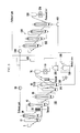
FIG. 1 is a view illustrating a constitution of a reduction apparatus of a fine direct reduced iron according to an exemplary embodiment of the present invention. -
FIG. 2 is a view illustrating the constitution of the reduction apparatus of the fine direct reduced iron according to the exemplary embodiment of the present invention, and illustrates that an intermediate reduction furnace is constituted by multi-stages (plural). -
FIG. 3 is a view illustrating the constitution of the reduction apparatus of the fine direct reduced iron according to the exemplary embodiment of the present invention, and illustrates that a final reduction furnace is constituted by a twin fluidized-bed reactor, that is, a granulated ore final reduction furnace and an ultra-fine ore final reduction furnace, and a magnetic separator is further disposed. -
FIG. 4 is a view schematically illustrating a constitution of an apparatus of manufacturing an ingot iron and a reduced iron according to another exemplary embodiment of the present invention.FIG. 4 illustrates that carbon dioxide is removed from an exhaust gas discharged from the apparatus of manufacturing the ingot iron and the reduced iron, and the exhaust gas is then blown back to the apparatus of manufacturing the reduced iron to manufacture the reduced iron. -
FIG. 5 is a view schematically illustrating the constitution of the apparatus of manufacturing the ingot iron and the reduced iron according to another exemplary embodiment of the present invention.FIG. 5 is a view illustrating that a reduction gas manufactured in a melting gasifier constituting the apparatus of manufacturing the ingot iron is branched to be supplied to each reduction furnace. -
FIG. 6 is a view schematically illustrating the apparatus of manufacturing the ingot iron and the reduced iron, in which the apparatus of manufacturing the reduced iron illustrated inFIG. 4 is changed into a shaft furnace. -
FIG. 7 is a view schematically illustrating the apparatus of manufacturing the ingot iron and the reduced iron, in which the apparatus of manufacturing the reduced iron illustrated inFIG. 5 is changed into the shaft furnace. - Advantages and features of the present invention and methods to achieve them will be elucidated from exemplary embodiments described below in detail with reference to the accompanying drawings. The present invention is not limited by the following disclosed exemplary embodiments but may be implemented in various different forms exemplary embodiments introduced herein are provided to make disclosed contents thorough and completely and sufficiently transfer the spirit of the present invention to those skilled in the art. Therefore, the present invention will be defined only by the scope of the appended claims. Like reference numerals designate like elements throughout the specification.
- Hereinafter, referring to the accompanying drawings, a reduction apparatus of a fine direct reduced iron according to an exemplary embodiment of the present invention includes a granulated
ore pre-reduction furnace 10 into which a fine iron ore is charged to be pre-reduced by a reduction gas; an ultra-fineore pre-reduction furnace 20 into which an ultra-fine ore scattered in the granulatedore pre-reduction furnace 10 to be discharged is charged to be pre-reduced, a firstmagnetic separator 30 separating a gangue component from the ultra-fine ore reduced in the ultra-fineore pre-reduction furnace 20 and then discharged; at least oneintermediate reduction furnace 40 into which the granulated ore reduced in the granulatedore pre-reduction furnace 10 to be discharged and the ultra-fine ore from which the gangue component is separated are charged to be further reduced and thus increase a reduction ratio of the granulated ore and the ultra-fine ore; and afinal reduction furnace 50 finally reducing the granulated ore and the ultra-fine ore reduced in theintermediate reduction furnace 40 to be discharged to manufacture a reduced iron. - As the fine iron ore, a low grade ore having a high gangue content such as SiO2 and Al2O3 may be used. The low grade ore may be a powder ore type. In the case where the low grade ore is fluidized and reduced, an ultra-minute ore (ultra-fine iron ore) generated by degradation during a fluidization and reduction process may include a large amount of gangue component.
- A particle size of the fine iron ore charged from a fine iron ore charging bath into the granulated ore pre-reduction furnace is 8 mm or less.
- In other words, when the iron ore is reduced from hematite (Fe2O3) to magnetite (Fe3O4), reduction degradation occurs due to volume expansion, further, the iron ore is degraded by thermal and mechanical impacts and the like during fluidization in a fluidized-reduction furnace, and the gangue component is concentrated in the ultra-minute ore generated by degradation.
- The powder ore type of fine iron ore is charged into the granulated
ore pre-reduction furnace 10 to be reduced to magnetite (Fe3O4) during a fluidization reduction process, and in this case, the ultra-fine ore scattered in the granulatedore pre-reduction furnace 10 to be discharged is charged into the ultra-fineore pre-reduction furnace 20 to be reduced into magnetite. - A particle size range of the granulated ore (granulated fine iron ore) corresponds to 0.1 to 8 mm. Further, a particle size range of the ultra-fine ore is 100 µm or less.
- As the granulated
ore pre-reduction furnace 10, a cylindrical type fluidized-reduction furnace may be used, and since an upper portion and a lower portion of a distributing plate are cylinders having the same diameter, the same fluidization occurs on the upper/lower portions of the distributing plate, and thus the ultra-fine (ultra-minute) ore having a predetermined particle size may be easily discharged through an outlet of an upper portion of the furnace. - Further, in the granulated
ore pre-reduction furnace 10, a cyclone for collecting fine powder scattered in a fluidized bed and re-collecting the fine powder back into the fluidized bed may not be disposed. - Meanwhile, as the ultra-fine
ore pre-reduction furnace 20, a fluidized bed reduction furnace may be used, and since the ultra-fineore pre-reduction furnace 20 has a shape where the furnace of the upper portion of the distributing plate is tapered, a flow of the reduction gas through the distributing plate becomes smooth as moving to an upper portion of the furnace, and thus the ultra-fine (ultra-minute) ore may be not scattered from the fluidized bed in a large amount, and a reduction reaction may easily occur in the fluidized bed. Further, fine powder scattered in the fluidized bed may be collected back to be re-collected in the fluidized bed by disposing the cyclone for collecting fine powder in the ultra-fineore pre-reduction furnace 20. - Temperature ranges of the granulated and ultra-fine
ore pre-reduction furnaces - Components of the reduction gas for reducing the fine iron ore in the pre-reduction furnace include CO, CO2, H2, H2O N2, and the like.
- In the case where the gangue is not sufficiently removed in a reduction step to magnetite, as will be described below, the gangue contained in a large amount in the ultra-fine ore (ultra-minute ore) may be further separated by using magnetic separation in a step of generating the reduced iron, which is a final reduction step.
- In this case, the fluidization reduction temperature in the final reduction step is 760°C or less, and the reduction gas includes CO, CO2 H2, H2O, N2, and the like.
- Since the content of the gangue is largely increased in the ultra-minute ore (ultra-fine ore) generated by degradation during a fluidization reduction reaction of the iron ore, a twin fluidized-bed reactor constituted by the granulated
ore pre-reduction furnace 10 and the ultra-fineore pre-reduction furnace 20 may be used in order to separate the fine iron ore into granules and ultra-fine particles in the reduction step of magnetite to reduce the fine iron ore. - That is, the charged iron ore is separated into the granules and ultra-minute particles in the reduction step to magnetite, the granules having the relatively small gangue content are reduced and then discharged to the fluidized-reduction furnace of a next step, and the ultra-minute particles having the high gangue content pass through the magnetic separator to separate the gangue to reduce the gangue content of the ore and then discharged to the fluidized-reduction furnace of the next step, thus continuously further reducing the granules and the ultra-minute particles.
- Further, as described above, in the case where a removal amount of the gangue of the ultra-minute particles in the reduction step of magnetite is not sufficient, the gangue component may be further removed from the ultra-minute particles degraded through an additional reduction step by using the twin fluidized-bed reactor in the final reduction step like the reduction step of magnetite to further improve a final grade of the reduced iron.
-
FIG. 1 is a fluidization reduction operation process, in which the fine iron ore is charged from a fine ironore charge bin 5 into the granulatedore pre-reduction furnace 10 that is one of the twin fluidized-reduction furnace and then fluidization-reduced into magnetite, the ultra-minute ore (ultra-fine iron ore) is scattered into the ultra-fineore pre-reduction furnace 20 to move, and only the granulated ore remains in the granulatedore pre-reduction furnace 10 to be fluidization-reduced and discharged to the fluidized-reduction furnace of the next step. - In
FIG. 1 , the distributing plate through which the reduction gas is blown is disposed in lower portions of insides of the ultra-fineore pre-reduction furnace 20, theintermediate reduction furnace 40, and thefinal reduction furnace 50, and the cyclone for collecting the fine ore is disposed in upper portions of insides of the furnaces. - Supplementary materials such as limestone and dolomite may be added together when the fine iron ore is reduced to be charged into the granulated
ore pre-reduction furnace 10. In the case where the reduced iron finally reduced to be discharged in the reduction apparatus of the fine iron ore of the present application is melted in subsequent melting furnaces, electric furnaces, and the like, the supplementary materials such as limestone and dolomite may be added in order to reduce a melting point of the gangue component contained in the reduced iron, melt the gangue component, and exhaust the gangue component in a slag form. - Meanwhile, the ultra-minute powder scattered immediately after charging while contained in the charged ore to move as well as the ultra-minute powder generated while the fine iron ore is degraded to magnetite in the granulated
ore pre-reduction furnace 10 is reduced to magnetite in the ultra-fineore pre-reduction furnace 20. - Further, only magnetite may be discharged to the
intermediate reduction furnace 40 as will be described next by charging the ultra-fine ore containing magnetite discharged after reduced in the ultra-fineore pre-reduction furnace 20 into the firstmagnetic separator 30 to separate the particles having a magnetic property, that is, magnetite, and the gangue that is a non-magnetic material from the ultra-fine ore. - As described above, separation efficiency in the magnetic separator may be largely increased and a capacity of the magnetic separator may be optimized by removing only the gangue of the ultra-fine ore having the high gangue content.
- The reduction apparatus of the fine iron ore may further include at least one
intermediate reduction furnace 40 into which the granulated ore reduced in the granulatedore pre-reduction furnace 10 to be discharged and the ultra-fine ore from which the gangue component is separated are charged to be further reduced, thereby increasing a reduction ratio of the granulated ore and the ultra-fine ore. - As illustrated in
FIG. 2 , theintermediate reduction furnace 40 may include a plurality of (multi-stage) sequentially connected fluidized-reduction furnaces - High grade magnetite having the increased grade sequentially passes through the fluidized-reduction furnaces of the next steps to be further reduced and thus be discharged as the high grade reduced iron after reduced in the
final reduction furnace 50. - As described above, the manufactured high grade reduced iron may be charged into the melting furnace to largely reduce the generation amount of the slag when an ingot iron is manufactured, thereby contributing to a reduction in reducing agent ratio to largely reduce a manufacturing cost of the ingot iron.
-
FIG. 3 is a view illustrating that thefinal reduction furnace 50 is constituted by the twin fluidized-reduction furnace, that is, a granulated orefinal reduction furnace 53 and an ultra-fine orefinal reduction furnace 55. - The
final reduction furnace 50 includes the granulated orefinal reduction furnace 53 into which the granulated ore and the ultra-fine ore are charged to manufacture the reduced iron, and the ultra-fine orefinal reduction furnace 55 into which the ultra-fine ore scattered in the granulated orefinal reduction furnace 53 to be discharged is charged to manufacture the reduced iron. - The reduction apparatus of the fine iron ore may further include a second magnetic separator 60 for removing the gangue component from the reduced iron discharged from the ultra-fine ore
final reducing furnace 55. - Meanwhile, in the sequentially connected fluidized-reduction furnaces, when the gangue component is separated by using the twin fluidized-reduction furnace for pre-reduction, in the case where a removal amount of the gangue of the ultra-fine ore is not sufficient, the
final reduction furnace 50 may be disposed in a twin fluidized-reduction furnace mode. - As described above, the granulated ore of the granulated ore and the fine ore sequentially passing through a reduction process in an entire step of the
final reduction furnace 50 may be finally reduced into the reduced iron in the granulated orefinal reduction furnace 53 by disposing thefinal reduction furnace 50 in the twin fluidized-reduction furnace mode. - Further, after the ultra-minute ore containing a large amount of the gangue scattered in the granulated ore
final reduction furnace 53 to move is further reduced in the ultra-fine orefinal reduction furnace 55 to manufacture the reduced iron, the reduced iron may be charged into the second magnetic separator 60 to separate a metallic iron having a magnetic property and the non-magnetic gangue to remove only the gangue and then exhaust only the metallic iron to a reducediron storage bin 70. - A temperature range of the granulated and ultra-fine ore
final reduction furnaces final reduction furnace 50 is present in a metallic iron (metallic Fe) form. A Curie temperature (threshold temperature at which the magnetic property is maintained) of the metallic iron is 768°C. - Accordingly, the content of the gangue of the reduced iron discharged in the fluidized-reduction furnace may be further reduced to produce the high grade reduced iron.
- A flow of the reduction gas is blown through the distributing plate at a lower portion of the final reduction furnace 50 (granulated and ultra-fine ore final reduction furnaces) to reduce the iron ore in the fluidized bed and then be discharged at an upper portion of the furnace, and the discharged reduction gas is blown through the distributing plate at a lower portion of the
intermediate reduction furnace 40 to reduce the iron ore in the fluidized bed and then be discharged at an upper portion of the furnace. - The reduction gas discharged from the
intermediate reduction furnace 40 is blown through the distributing plate at lower portions of the granulated and ultra-minute ore pre-reduction furnaces to pre-heat and pre-reduce the iron ore and then be discharged at upper portions of the pre-reduction furnaces, and the discharged reduction gas (exhaust gas) is subjected to cooling and dust elimination processes by ascrubber 80 and the like. - That is, in the reduction apparatus of the fine iron ore according to the present invention, a direction where the iron ore is reduced and then progresses is opposite to a progress direction of the reduction gas.
-
FIGS. 4 and5 are views schematically illustrating a constitution of an apparatus of manufacturing the ingot iron and the reduced iron according to the exemplary embodiment of the present invention. - Referring to
FIGS. 4 and5 , the apparatus of manufacturing the ingot iron and the reduced iron according to the present invention includes afirst reduction apparatus 100 including a multi-stage fluidized-reduction furnace and the magnetic separator, acharge bin 200 for storing or further reducing the reduced iron manufactured by thefirst reduction apparatus 100, amelting gasifier 300 into which the reduced iron discharged from thecharge bin 200 and a breeze supplied from an outside are charged and oxygen is blown to manufacture the ingot iron and a reduction gas, asecond reduction apparatus 500 disposed to be spaced apart from thefirst reduction apparatus 100 and including a multi-stage fluidized-reduction furnace 530 or ashaft furnace 600, and a first reformingapparatus 430 removing carbon dioxide from an exhaust gas discharged from thefirst reduction apparatus 100 and thesecond reduction apparatus 500 and then branched, the reduction gas manufactured in themelting gasifier 300 is supplied to thefirst reduction apparatus 100, and the exhaust gas from which carbon dioxide is removed by the first reformingapparatus 430 is supplied to thesecond reduction apparatus 500. - The
first reduction apparatus 100 includes the reduction apparatus of the fine direct reduced iron based on the aforementionedFIGS. 1 to 3 . - The reduced iron manufactured in the
first reduction apparatus 100 is stored in thecharge bin 200 before charged into amelting reduction furnace 300 for final reduction. The reduced iron stored in thecharge bin 200 may be further reduced by the reduction gas generated in themelting reduction furnace 300. - The reduced iron manufactured by the
first reduction apparatus 100 may be temporarily stored in afirst storage bin 70 before supplied to thecharge bin 200. - The reduced iron discharged from the
first storage bin 70 may be supplied to thecharge bin 200 by being agglomerated through a first agglomeratingbody manufacturing apparatus 110 before supplied to thecharge bin 200. - The reduced iron discharged from the
charge bin 200 and a breeze supplied from anexternal breeze supplier 250 are charged and oxygen is then blown into themelting reduction furnace 300 to melt the reduced iron by combustion heat of the breeze to manufacture the ingot iron and generate the reduction gas by combustion of the breeze. - The
second reduction apparatus 500 is disposed to be spaced apart from thefirst reduction apparatus 100 including the multi-stage fluidized-reduction furnace and the magnetic separator, and reduces the iron ore to manufacture the reduced iron. Thesecond reduction apparatus 500 may include the multi-stage fluidized-reduction furnace 530 or theshaft furnace 600. - Meanwhile, the exhaust gas discharged from the multi-stage fluidized-reduction furnace constituting the
first reduction apparatus 100 and the exhaust gas discharged from thesecond reduction apparatus 500 pass throughscrubbers 80 and 150, respectively, to remove impurities such as dust, are branched, and pass through the first reformingapparatus 430 to remove carbon dioxide contained in the exhaust gas and thus increase the content of the reduction gas such as carbon monoxide and hydrogen in the exhaust gas. - In the case where the
second reduction apparatus 500 includes the multi-stage fluidized-reduction furnace 530, the fine iron ore is charged to manufacture the reduced iron by the reduction gas, and in the case where thesecond reduction apparatus 500 includes theshaft furnace 600, a pellet obtained by processing the fine iron ore is charged to manufacture the reduced iron by the reduction gas. - Meanwhile, a portion of the exhaust gas discharged from the
first reduction apparatus 100 is branched to be mixed with the reduction gas discharged from themelting gasifier 300. - In this case, before the exhaust gas is mixed with the reduction gas discharged from the
melting reduction furnace 300, carbon dioxide is removed from the exhaust gas through a second reformingapparatus 420 to increase the content of the reduction gas such as carbon monoxide and hydrogen contained in the exhaust gas. Before the exhaust gas is supplied to the second reformingapparatus 420, the exhaust gas may pass through acompressor 410 to manufacture a compression gas. - By mixing the reduction gas discharged from the
melting gasifier 300 with the exhaust gas from which carbon dioxide is removed, the temperature of the reduction gas may be adjusted to a temperature (700 to 800°C) suitable to reduce the iron ore in the multi-stage fluidized-reduction furnace constituting thefirst reduction apparatus 100. - Further, the reduction gas discharged from the
melting gasifier 300 and then mixed with the exhaust gas from which carbon dioxide is removed passes through aparticle separation apparatus 330 to separate particles, the separated particles are re-charged into themelting gasifier 300, and the reduction gas from which the particles are separated is supplied to thefirst reduction apparatus 100 or thecharge bin 200. - A cyclone may be used as the particle separation apparatus.
- Before the exhaust gas from which carbon dioxide is removed by the first reforming
apparatus 430 is supplied to thesecond reduction apparatus 500, the exhaust gas may pass through atemperature increasing apparatus 450 to increase the temperature to a temperature suitable to reduce the iron ore. - An oxygen burner, a LNG burner, and the like may be used as the
temperature increasing apparatus 450. - Meanwhile, in the case where the
second reduction apparatus 500 includes the multi-stage fluidized-reduction furnace 530, before the reduced iron manufactured in thesecond reduction apparatus 530 is manufactured in an agglomerate form, asecond storage bin 550 temporarily storing the reduced iron may be further included. - Further, a second agglomerating body manufacturing apparatus 570 for agglomerating the reduced iron discharged from the
second storage bin 550 may be further included. -
FIG. 6 illustrates a modified exemplary embodiment of the apparatus of manufacturing the ingot iron and the reduced iron illustrated inFIG. 4 , and a second reduced iron manufacturing apparatus includes theshaft furnace 600. - The pellet obtained by agglomerating the fine iron ore is charged into the
shaft furnace 600 to reduce the iron ore by blowing a reformed gas (exhaust gas from which carbon dioxide is removed) obtained by removing carbon dioxide from the exhaust gas, and thus the reduced iron is manufactured. -
FIGS. 5 and6 are views illustrating an apparatus of manufacturing an ingot iron and a reduced iron according to another exemplary embodiment of the present invention. - As illustrated in
FIGS. 5 and6 , the apparatus of manufacturing the ingot iron and the reduced iron according to the present invention includes afirst reduction apparatus 100 including a multi-stage fluidized-reduction furnace and a magnetic separator, acharge bin 200 for storing or further reducing the reduced iron manufactured by thefirst reduction apparatus 100, amelting gasifier 300 into which the reduced iron discharged from thecharge bin 200 and a breeze supplied from an outside are charged and oxygen is blown to manufacture the ingot iron and a reduction gas, asecond reduction apparatus 500 disposed to be spaced apart from thefirst reduction apparatus 100 and including a multi-stage fluidized-reduction furnace 530 or ashaft furnace 600, and a first reformingapparatus 430 removing carbon dioxide from an exhaust gas discharged from thefirst reduction apparatus 100 and thesecond reduction apparatus 500 and then branched, and the reduction gas discharged from themelting gasifier 300 is mixed with the exhaust gas from which carbon dioxide is removed, and then supplied to thefirst reduction apparatus 100 and thesecond reduction apparatus 500. - The
first reduction apparatus 100 includes the reduction apparatus of the fine direct reduced iron based on the aforementionedFIGS. 1 to 3 . - The reduced iron manufactured in the
first reduction apparatus 100 is stored in thecharge bin 200 before charged into amelting reduction furnace 300 for final reduction. The reduced iron stored in thecharge bin 200 may be further reduced by the reduction gas generated in themelting reduction furnace 300. - The reduced iron manufactured by the
first reduction apparatus 100 may be temporarily stored in afirst storage bin 70 before supplied to thecharge bin 200. - The reduced iron discharged from the
first storage bin 70 may be supplied to thecharge bin 200 by being agglomerated through a first agglomeratingbody manufacturing apparatus 110 before supplied to thecharge bin 200. - The reduced iron discharged from the
charge bin 200 and a breeze supplied from anexternal breeze supplier 250 are charged and oxygen is then blown into themelting reduction furnace 300 to melt the reduced iron by combustion heat of the breeze to manufacture the ingot iron and generate the reduction gas by combustion of the breeze. - The
second reduction apparatus 500 is disposed to be spaced apart from thefirst reduction apparatus 100 including the multi-stage fluidized-reduction furnace and the magnetic separator, and reduces the iron ore to manufacture the reduced iron. Thesecond reduction apparatus 500 may include the multi-stage fluidized-reduction furnace 530 or theshaft furnace 600. - Further, the first reforming
apparatus 430 removes carbon dioxide from the exhaust gas discharged from thefirst reduction apparatus 100 and thesecond reduction apparatus 500 and then branched. - The exhaust gas from which carbon dioxide is removed is mixed with the reduction gas discharged from the
melting gasifier 300, and the reduction gas mixed with the exhaust gas from which carbon dioxide is removed is supplied to thefirst reduction apparatus 100 and thesecond reduction apparatus 500. - In the case where the reduction gas discharged from the
melting gasifier 300 is rich, the reduction gas may be supplied to thesecond reduction apparatus 500 as well as thefirst reduction apparatus 100 to increase a production capacity of the ingot iron and the reduced iron. - The case where the capacity of the reduction gas generated in the
melting gasifier 300 is increased may correspond to the case where the capacity of the breeze charged into themelting gasifier 300 is increased, that is, the case where a coal ratio is increased. - That is, the reduction gas may be supplied to the reduction apparatus (e.g., first reduction apparatus) directly connected to the
melting gasifier 300 and the separately installed reduced iron manufacturing apparatus (e.g., second reduction apparatus) by increasing the coal ratio to generate a large amount of the reduction gas in themelting gasifier 300 to increase productivity of the ingot iron and the reduced iron. - A portion of the reduction gas discharged from the
melting gasifier 300 and then mixed with the exhaust gas from which carbon dioxide is removed may be supplied to thecharge bin 200 and thus be used to further reduce the reduced iron stored in thecharge bin 200. - The reduction gas discharged from the
melting gasifier 300 and then mixed with the exhaust gas from which carbon dioxide is removed passes through aparticle separation apparatus 330 to separate particles, the separated particles are re-charged into themelting gasifier 300, and the reduction gas from which the particles are separated is supplied to thefirst reduction apparatus 100 and thesecond reduction apparatus 500. -
FIG. 7 illustrates a modified exemplary embodiment of the apparatus of manufacturing the ingot iron and the reduced iron illustrated inFIG. 5 , and a second reducediron manufacturing apparatus 500 includes theshaft furnace 600. - The pellet obtained by agglomerating the fine iron ore is charged into the
shaft furnace 600 to reduce the iron ore by blowing a reformed gas (exhaust gas from which carbon dioxide is removed) obtained by removing carbon dioxide from the exhaust gas, and thus the reduced iron is manufactured. - A method of manufacturing an ingot iron and a reduced iron according to another exemplary embodiment of the present invention includes manufacturing the reduced iron by performing magnetic separation while reducing a fine iron ore by using a multi-stage fluidized-reduction furnace and a magnetic separation apparatus, manufacturing the ingot iron and a reduction gas by charging the reduced iron and a breeze supplied from an outside into a melting gasifier and then blowing oxygen, further manufacturing the reduced iron by reducing the fine iron ore or a pellet by a reduction apparatus disposed to be spaced apart from the multi-stage fluidized-reduction furnace, and branching an exhaust gas discharged from the multi-stage fluidized-reduction furnace and the reduction apparatus and then removing carbon dioxide, the reduction gas manufactured in the melting gasifier is supplied to the multi-stage fluidized-reduction furnace, and the exhaust gas from which carbon dioxide is removed is supplied to the reduction apparatus.
- The reduced iron manufactured by the multi-stage fluidized-reduction furnace and the magnetic separation apparatus may be supplied to a charge bin to be temporarily stored or further reduced before charged into the melting gasifier.
- After a portion of the exhaust gas discharged from the multi-stage fluidized-reduction furnace is branched, carbon dioxide may be removed therefrom, and the portion of the exhaust gas may be mixed with the reduction gas discharged from the melting gasifier.
- Particles may be separated from the reduction gas discharged from the melting gasifier and then mixed with the exhaust gas from which carbon dioxide is removed, the separated particles may be re-charged into the melting gasifier, and the reduction gas from which the particles are separated may be supplied to the multi-stage fluidized-reduction furnace or the charge bin.
- The reduction apparatus is the multi-stage fluidized-reduction furnace or a shaft furnace.
- Meanwhile, a method of manufacturing an ingot iron and a reduced iron according to another exemplary embodiment of the present invention includes manufacturing the reduced iron by performing magnetic separation while reducing a fine iron ore by using a multi-stage fluidized-reduction furnace and a magnetic separation apparatus, manufacturing the ingot iron and a reduction gas by charging the reduced iron and a breeze supplied from an outside into a melting gasifier and then blowing oxygen, and further manufacturing the reduced iron by reducing the fine iron ore or a pellet by a reduction apparatus disposed to be spaced apart from the multi-stage fluidized-reduction furnace, and the reduction gas manufactured in the melting gasifier is supplied to the multi-stage fluidized-reduction furnace and the reduction apparatus.
- After a portion of the exhaust gas discharged from the multi-stage fluidized-reduction furnace is branched, carbon dioxide may be removed therefrom, and the portion of the exhaust gas may be mixed with the reduction gas discharged from the melting gasifier.
- Hereinafter, a method of reducing the fine iron ore according to the present invention will be described in detail through an Example. However, the following Example is set forth to illustrate the present invention, but the content of the present invention is not limited by the following Example.
- In the case where high grade hematite having the total metallic iron (T.Fe) content of 62% and containing 3.76% of SiO2 and 2.23% of Al2O3 among the gangue components was mixed with limestone and dolomite which were supplementary materials to be fluidization-reduced in the fluidized-reduction furnace at 450°C, the iron ore was converted into the reduced ore having the reduction ratio of 10%, that is, magnetite, in the fluidized bed.
- In this case, the content of silica (SiO2) of the iron ore in the fluidized bed was 3.60% and the content of alumina (Al2O3) was 1.65%, but in the ultra-minute powder scattered in the same reactor, the content of SiO2 was increased to 4.50% and the content of Al2O3 was increased to 1.67%, and particularly, the content of SiO2 of the ultra-minute powder not collected by the cyclone in the reactor but scattered and lost was 7.80% and the content of Al2O3 was 4.83%, and thus the content of the gangue was largely increased.
- Accordingly, after the gangue of the scattered ultra-minute powder having the high gangue content was separated and removed, when recycling was performed, the content of the gangue component in the reduced iron was reduced and thus the high grade reduced iron could be manufactured.
- Meanwhile, in the case where separation of the gangue was not sufficient in the reduction step of magnetite, by performing additional fluidization reduction, the content of the ultra-minute powder was increased by additional degradation in the final fluidization reduction step at 750°C, and the content of the gangue in the ultra-minute powder was increased, and thus the content of SiO2 was 5.15% and the content of Al2O3 was 2.63%, which exhibited the high contents as compared to the SiO2 content of 4.17% and the Al2O3 content of 2.03% of the reduced iron in the reactor. Accordingly, the gangue component could be further removed by performing magnetic separation of the metallic iron and the gangue of the ultra-minute powder.
- In the case of the Example of the present invention, the reduction gas supply pressure was 3.8 bar, the exhaust gas flow rate was 180,000 Nm3/hr, the temperature of the reactor was 750°C (final reduction furnace), 700°C (intermediate reduction furnace), and 450°C (pre-reduction furnace ).
(Table 1) Analysis results of the reduced iron component discharged from the final reduction furnace before and after the present invention is applied Comparison items Magnetic separation is not applied After pre-reduction furnace magnetic separation After pre-reduction furnace and final reduction furnace magnetic separation Reduction ratio (%) 60 60 60 SiO2 (%) 4.3 3.3 2.5 Al2O3 (%) 2.5 2.0 1.6 - In the case where the reduced iron was manufactured by the fluidization reduction process where the gangue component contained in the ultra-minute powder was removed by magnetic separation in the reduction step of magnetite of the fluidization reduction process, from a comparison result with an operation result in the existing fluidized-reduction furnace, it could be confirmed that the reduction ratios of the reduced iron were the same but the contents of SiO2 and Al2O3 that were the gangue components were largely reduced.
- Further, as illustrated in
FIGS. 4 to 7 , in the case where the reduction gas obtained by reforming the exhaust gas was supplied to the separate reduction apparatus and the case where the reduction gas generated in the melting gasifier was branched and supplied to individual reduction apparatuses according to the exemplary embodiment and the modified exemplary embodiment of the present invention, production amounts and reduction ratios of the reduced iron were evaluated. - As described in Table 2, it can be seen that the reduced iron having the high reduction ratio or the same level of reduction ratio can be further produced.
(Table 2) Production amount and reduction ratio of the reduced iron further produced by applying the present invention Classification Case where the separate reduction apparatus is not added Case where the separate reduction apparatus is added Before magnetic separation After magnetic separation (pre- and final reduction step) Fluidization reduction apparatus Pellet reduction apparatus Case where the reduction gas obtained by reforming the exhaust gas is Case where the reduction gas generated in the melting gasifier is branched to Case where the reduction gas obtained by reforming the exhaust gas is supplied to the separate Case where the reduction gas generated in the melting gasifier is branched to be supplied supplied to the separate reduction apparatus be supplied to the reduction apparatus reduction apparatus to the separate reduction apparatus Reduced iron production amount (t/d) 112 110 128 110 100 110 Reduction ratio (%) 60 60 65 60 85 60 - The present invention may provide an apparatus and a method of manufacturing a reduced iron, in which a gangue component of a low grade ore can be effectively removed and separated in a fluidization reduction process.
- That is, in a step of generating magnetite from hematite of the fluidization reduction process of an iron ore, ultra-minute powder (ultra-fine iron ore) generated in a large amount by reduction degradation due to volume expansion and impact during fluidization is scattered to be mostly collected by a cyclone in a fluidized-reduction furnace and thus recycled or to be discharged to the outside of a fluidized-reduction reactor and thus lost.
- Since the ultra-minute powder scattered in the fluidized-reduction reactor contains a large amount of gangue, if only the gangue is effectively separated and removed by magnetic separation by using a magnetic property of magnetite, the low grade ore may be converted into a high grade ore by performing mineral dressing in the fluidization reduction process to reduce a gangue content of the ore in the fluidized-bed reactor.
- Further, in the case where separation of the gangue in the step of generating magnetite is not sufficient, reduction may be continuously performed through an additional fluidization reduction process, and the gangue included in the ultra-minute powder may be removed by magnetic separation in a final reduction step where a metallic iron is generated and degradation occurs to further improve the grade of a reduced iron manufactured in the fluidization reduction process and reduce an amount of slag generated when an ingot iron is manufactured by using the same, thus reducing a reducing agent ratio.
- Further, the reduced iron may be further produced by supplying a reformed gas obtained by reforming an exhaust gas discharged from a reduction apparatus to a separately installed reduction apparatus, and productivity of the reduced iron may be increased by branching a reduction gas discharged from a melting gasifier and supplying the reduction gas to individual reduction apparatuses.
- Although the exemplary embodiments of the present invention have been described with reference to the accompanying drawings, it will be apparent to those skilled in the art that various modifications and changes may be made thereto without departing from the technical spirit or essential feature of the invention.
- Therefore, the aforementioned embodiments should be understood to be exemplary but not limiting in any way. The scope of the present invention is represented by the claims as described later rather than the detailed description, and it is to be construed that all modifications and modified embodiments deduced from the meaning and the scope of the claims, and the equivalent concept thereto are included within the scope of the present invention.
Claims (27)
- A reduction apparatus of a fine iron ore comprising:a granulated ore pre-reduction furnace into which the fine iron ore is charged to be pre-reduced by a reduction gas;an ultra-fine ore pre-reduction furnace into which an ultra-fine ore scattered in the granulated ore pre-reduction furnace to be discharged is charged to be pre-reduced;a first magnetic separator separating a gangue component from the ultra-fine ore reduced in the ultra-fine ore pre-reduction furnace and then discharged;at least one intermediate reduction furnace into which the granulated ore reduced in the granulated ore pre-reduction furnace to be discharged and the ultra-fine ore from which the gangue component is separated are charged to be further reduced and thus increase a reduction ratio of the granulated ore and the ultra-fine ore; anda final reduction furnace finally reducing the granulated ore and the ultra-fine ore reduced in the intermediate reduction furnace to be discharged to manufacture a reduced iron.
- The reduction apparatus of claim 1, wherein:the intermediate reduction furnace includes a plurality of sequentially connected fluidized-reduction furnaces.
- The reduction apparatus of claim 1 or 2, wherein:the final reduction furnace includes a granulated ore final reduction furnace into which the granulated ore and the ultra-fine ore reduced in the intermediate reduction furnace are charged to manufacture the reduced iron; andan ultra-fine ore final reduction furnace into which the ultra-fine ore scattered in the granulated ore final reduction furnace to be discharged is charged to manufacture the reduced iron.
- The reduction apparatus of claim 3, further comprising:a second magnetic separator for removing the gangue component from the reduced iron discharged from the ultra-fine ore final reduction furnace.
- An apparatus of manufacturing an ingot iron and a reduced iron, comprising:a first reduction apparatus including the reduction apparatus according to any one of claims 1 to 4;a charge bin for storing or further reducing the reduced iron manufactured by the first reduction apparatus;a melting gasifier into which the reduced iron discharged from the charge bin and a breeze supplied from an outside are charged and oxygen is blown to manufacture the ingot iron and a reduction gas;a second reduction apparatus disposed to be spaced apart from the first reduction apparatus and including a multi-stage fluidized-reduction furnace or a shaft furnace; anda first reforming apparatus removing carbon dioxide from an exhaust gas discharged from the first reduction apparatus and the second reduction apparatus and then branched,wherein the reduction gas manufactured in the melting gasifier is supplied to the first reduction apparatus, andthe exhaust gas from which carbon dioxide is removed by the first reforming apparatus is supplied to the second reduction apparatus.
- The apparatus of claim 5, further comprising:a second reforming apparatus removing carbon dioxide from the exhaust gas before a portion of the exhaust gas discharged from the first reduction apparatus is branched and then mixed with the reduction gas discharged from the melting gasifier.
- The apparatus of claim 6, further comprising:a particle separation apparatus separating particles from the reduction gas discharged from the melting gasifier and then mixed with the exhaust gas from which carbon dioxide is removed, re-charging the separated particles into the melting gasifier, andsupplying the reduction gas from which the particles are separated to the first reduction apparatus or the charge bin.
- The apparatus of claim 7, further comprising:a temperature increasing apparatus for increasing a temperature of the exhaust gas to a predetermined temperature before the exhaust gas from which carbon dioxide is removed by the first reforming apparatus is supplied to the second reduction apparatus.
- The apparatus of claim 5, further comprising:a first storage bin for temporarily storing the reduced iron manufactured in the first reduction apparatus before supplied to the charge bin.
- The apparatus of claim 9, further comprising:a first agglomerating body manufacturing apparatus for agglomerating the reduced iron discharged from the first storage bin before supplied to the charge bin.
- The apparatus of claim 5, further comprising:in the case where the second reduction apparatus includes the multi-stage fluidized-reduction furnace,a second storage bin temporarily storing the reduced iron manufactured in the second reduction apparatus before manufactured in an agglomerate form.
- The apparatus of claim 11, further comprising:a second agglomerating body manufacturing apparatus for agglomerating the reduced iron discharged from the second storage bin.
- An apparatus of manufacturing an ingot iron and a reduced iron, comprising:a first reduction apparatus including the reduction apparatus according to any one of claims 1 to 4;a charge bin for storing or further reducing the reduced iron manufactured by the first reduction apparatus;a melting gasifier into which the reduced iron discharged from the charge bin and a breeze supplied from an outside are charged and oxygen is blown to manufacture the ingot iron and a reduction gas;a second reduction apparatus disposed to be spaced apart from the first reduction apparatus and including a multi-stage fluidized-reduction furnace or a shaft furnace; anda first reforming apparatus removing carbon dioxide from an exhaust gas discharged from the first reduction apparatus and the second reduction apparatus and then branched,wherein the reduction gas discharged from the melting gasifier is mixed with the exhaust gas from which carbon dioxide is removed, and then supplied to the first reduction apparatus and the second reduction apparatus.
- The apparatus of claim 13, wherein:a portion of the reduction gas discharged from the melting gasifier and then mixed with the exhaust gas from which carbon dioxide is removed is supplied to the charge bin.
- The apparatus of claim 13 or 14, further comprising:a particle separation apparatus separating particles and gases from the reduction gas discharged from the melting gasifier and then mixed with the exhaust gas from which carbon dioxide is removed.
- A method of manufacturing an ingot iron and a reduced iron, comprising:manufacturing the reduced iron by performing magnetic separation while reducing a fine iron ore by using a multi-stage fluidized-reduction furnace and a magnetic separation apparatus;manufacturing the ingot iron and a reduction gas by charging the reduced iron and a breeze supplied from an outside into a melting gasifier and then blowing oxygen;further manufacturing the reduced iron by reducing the fine iron ore or a pellet by a reduction apparatus disposed to be spaced apart from the multi-stage fluidized-reduction furnace; andbranching an exhaust gas discharged from the multi-stage fluidized-reduction furnace and the reduction apparatus and then removing carbon dioxide,wherein the reduction gas manufactured in the melting gasifier is supplied to the multi-stage fluidized-reduction furnace, andthe exhaust gas from which carbon dioxide is removed is supplied to the reduction apparatus.
- The method of claim 16, further comprising:supplying the reduced iron manufactured by the multi-stage fluidized-reduction furnace and a magnetic separation apparatus to a charge bin in order to store or further reduce the reduced iron before charged into the melting gasifier.
- The method of claim 16, further comprising:agglomerating the reduced iron manufactured by the multi-stage fluidized-reduction furnace and the magnetic separation apparatus.
- The method of claim 16, further comprising:branching a portion of the exhaust gas discharged from the multi-stage fluidized-reduction furnace, then removing carbon dioxide, and mixing the portion of the exhaust gas with the reduction gas discharged from the melting gasifier.
- The method of claim 19, further comprising:separating particles from the reduction gas discharged from the melting gasifier and then mixed with the exhaust gas from which carbon dioxide is removed, re-charging the separated particles into the melting gasifier, andsupplying the reduction gas from which the particles are separated to the multi-stage fluidized-reduction furnace or the charge bin.
- The method of claim 16, wherein:
the reduction apparatus is the multi-stage fluidized-reduction furnace or a shaft furnace. - A method of manufacturing an ingot iron and a reduced iron, comprising:manufacturing the reduced iron by performing magnetic separation while reducing a fine iron ore by using a multi-stage fluidized-reduction furnace and a magnetic separation apparatus;manufacturing the ingot iron and a reduction gas by charging the reduced iron and a breeze supplied from an outside into a melting gasifier and then blowing oxygen; andfurther manufacturing the reduced iron by reducing the fine iron ore or a pellet by a reduction apparatus disposed to be spaced apart from the multi-stage fluidized-reduction furnace,wherein the reduction gas manufactured in the melting gasifier is supplied to the multi-stage fluidized-reduction furnace and the reduction apparatus.
- The method of claim 22, further comprising:supplying the reduced iron manufactured by the multi-stage fluidized-reduction furnace and a magnetic separation apparatus to a charge bin in order to store or further reduce the reduced iron before charged into the melting gasifier.
- The method of claim 22, further comprising:agglomerating the reduced iron manufactured by the multi-stage fluidized-reduction furnace and the magnetic separation apparatus.
- The method of claim 22, further comprising:branching a portion of an exhaust gas discharged from the multi-stage fluidized-reduction furnace, then removing carbon dioxide, and mixing the portion of the exhaust gas with the reduction gas discharged from the melting gasifier.
- The method of claim 25, further comprising:separating particles from the reduction gas discharged from the melting gasifier and then mixed with the exhaust gas from which carbon dioxide is removed, re-charging the separated particles into the melting gasifier, andsupplying the reduction gas from which the particles are separated to the multi-stage fluidized-reduction furnace or the charge bin.
- The method of claim 22, wherein:the reduction apparatus is the multi-stage fluidized-reduction furnace or a shaft furnace.
Applications Claiming Priority (2)
| Application Number | Priority Date | Filing Date | Title |
|---|---|---|---|
| KR1020110145302A KR101353456B1 (en) | 2011-12-28 | 2011-12-28 | Apparatus for reducing iron ores and apparataus for manufacturing molten iron and reduced iron and method for manufacturing the same |
| PCT/KR2012/008244 WO2013100333A1 (en) | 2011-12-28 | 2012-10-11 | Iron ore powder reducing device, molten iron and reduced iron producing device and method for same |
Publications (3)
| Publication Number | Publication Date |
|---|---|
| EP2799558A1 true EP2799558A1 (en) | 2014-11-05 |
| EP2799558A4 EP2799558A4 (en) | 2015-12-23 |
| EP2799558B1 EP2799558B1 (en) | 2017-03-08 |
Family
ID=48697756
Family Applications (1)
| Application Number | Title | Priority Date | Filing Date |
|---|---|---|---|
| EP12861801.4A Active EP2799558B1 (en) | 2011-12-28 | 2012-10-11 | Iron ore powder reducing device, molten iron and reduced iron producing device and method for same |
Country Status (4)
| Country | Link |
|---|---|
| EP (1) | EP2799558B1 (en) |
| KR (1) | KR101353456B1 (en) |
| CN (1) | CN104185686B (en) |
| WO (1) | WO2013100333A1 (en) |
Families Citing this family (4)
| Publication number | Priority date | Publication date | Assignee | Title |
|---|---|---|---|---|
| CN106319126B (en) * | 2016-09-28 | 2019-05-17 | 中国科学院过程工程研究所 | One kind being used for the redox system and method for vanadium titano-magnetite fluidization |
| CN107299177B (en) * | 2017-05-25 | 2019-04-30 | 北京大学 | A fluid-solid coupling iron ore powder reduction device and method |
| US20230102312A1 (en) * | 2021-07-30 | 2023-03-30 | Ohio State Innovation Foundation | Systems and methods for generating hydrogen and magnetite from rock |
| CN117344076B (en) * | 2023-10-27 | 2024-11-12 | 攀钢集团西昌钢钒有限公司 | A method and device for direct reduction of iron ore step by step |
Family Cites Families (12)
| Publication number | Priority date | Publication date | Assignee | Title |
|---|---|---|---|---|
| KR940008466B1 (en) * | 1991-01-21 | 1994-09-15 | 주식회사 세원 | Preparing method of sizing agent |
| KR100256341B1 (en) * | 1995-12-26 | 2000-05-15 | 이구택 | Two-stage fluidized bed preliminary reduction apparatus for iron ore and its method |
| KR100301993B1 (en) * | 1996-12-24 | 2001-11-22 | 이구택 | Method for treating dust in electric furnace |
| KR100262486B1 (en) * | 1997-12-24 | 2002-04-17 | 이구택 | Reduction process and equipment and smelting reduction equipment of fine iron ore |
| KR100276347B1 (en) | 1998-07-31 | 2000-12-15 | 이구택 | A fluidized-bed apparatus for reducing fine iron ore and a method therefor |
| EP1109940B1 (en) * | 1999-06-21 | 2003-08-13 | POHANG IRON & STEEL CO., LTD. | 2-stage fluidized bed type fine iron ore reducing apparatus, and reducing method using the apparatus |
| JP2002363624A (en) * | 2001-06-13 | 2002-12-18 | Mitsubishi Heavy Ind Ltd | Reduced iron manufacturing method and manufacturing facility |
| KR100568339B1 (en) * | 2001-08-24 | 2006-04-05 | 주식회사 포스코 | Method for manufacturing molten iron in a molten reduction device for recycling iron-containing dust |
| AU2004295629B2 (en) * | 2003-12-05 | 2008-11-20 | Posco | An apparatus for manufacturing a molten iron directly using fine or lump coals and fine iron ores, the method thereof, the integrated steel mill using the same and the method thereof |
| KR100930680B1 (en) | 2007-12-26 | 2009-12-09 | 주식회사 포스코 | Molten iron manufacturing equipment and molten iron manufacturing method |
| CN101519707B (en) * | 2008-02-28 | 2010-12-01 | 宝山钢铁股份有限公司 | A multi-stage fluidized bed device and process for pre-reduction of fine iron ore |
| CN101660017B (en) * | 2008-08-28 | 2011-04-13 | 宝山钢铁股份有限公司 | Process for refining molten iron by directly using low-grade iron ores |
-
2011
- 2011-12-28 KR KR1020110145302A patent/KR101353456B1/en active Active
-
2012
- 2012-10-11 WO PCT/KR2012/008244 patent/WO2013100333A1/en not_active Ceased
- 2012-10-11 EP EP12861801.4A patent/EP2799558B1/en active Active
- 2012-10-11 CN CN201280064020.4A patent/CN104185686B/en not_active Expired - Fee Related
Also Published As
| Publication number | Publication date |
|---|---|
| KR101353456B1 (en) | 2014-01-21 |
| EP2799558B1 (en) | 2017-03-08 |
| EP2799558A4 (en) | 2015-12-23 |
| CN104185686B (en) | 2016-02-24 |
| KR20130076638A (en) | 2013-07-08 |
| WO2013100333A1 (en) | 2013-07-04 |
| CN104185686A (en) | 2014-12-03 |
Similar Documents
| Publication | Publication Date | Title |
|---|---|---|
| US8632622B2 (en) | Process and device for producing pig iron or liquid steel precursors | |
| US20130098202A1 (en) | Process for producing molten steel using granular metallic iron | |
| JP2015519473A (en) | Nonferrous metallurgical slag processing method | |
| EP2799558B1 (en) | Iron ore powder reducing device, molten iron and reduced iron producing device and method for same | |
| WO2024062922A1 (en) | Method for producing iron source | |
| US4629506A (en) | Process for the production of ferrochromium | |
| CN102046817A (en) | Method for manufacturing pig iron | |
| JPH0429732B2 (en) | ||
| CN112779376B (en) | Method for flash reduction treatment of schreyerite | |
| CN103282521B (en) | The manufacture method of reduced iron and manufacturing installation | |
| WO2015041834A2 (en) | Steel production in a coke dry quenching system | |
| JPH10147806A (en) | Production method of high-grade reduced iron from ironmaking dust | |
| JP6137087B2 (en) | Method for producing sintered ore | |
| CN111635997A (en) | Method for smelting nickel-iron alloy by hydrogen direct reduction smelting laterite nickel ore | |
| AU2017299295B2 (en) | Method for improving iron grade of iron ore | |
| KR100568339B1 (en) | Method for manufacturing molten iron in a molten reduction device for recycling iron-containing dust | |
| JP2013100582A (en) | Method for modifying iron-making raw material | |
| JPH01149912A (en) | Method of charging exhaust gas dust in a smelting reduction furnace | |
| CN105723002B (en) | Manufacturing method and manufacturing equipment of reduced iron | |
| ES3062717T3 (en) | Process for the utilization of fractions resulting from the direct reduction of iron ore supports with ammonia containing or a reduction gas composed of ammonia | |
| JP2014031528A (en) | Method for producing raw material for blast furnace | |
| JP5915864B2 (en) | Agglomerate production method | |
| JP2018095894A (en) | Production method of high quality iron source | |
| JP2018095895A (en) | Production method of high quality iron source | |
| WO2025227186A1 (en) | Production of iron and steel |
Legal Events
| Date | Code | Title | Description |
|---|---|---|---|
| PUAI | Public reference made under article 153(3) epc to a published international application that has entered the european phase |
Free format text: ORIGINAL CODE: 0009012 |
|
| 17P | Request for examination filed |
Effective date: 20140709 |
|
| AK | Designated contracting states |
Kind code of ref document: A1 Designated state(s): AL AT BE BG CH CY CZ DE DK EE ES FI FR GB GR HR HU IE IS IT LI LT LU LV MC MK MT NL NO PL PT RO RS SE SI SK SM TR |
|
| DAX | Request for extension of the european patent (deleted) | ||
| RA4 | Supplementary search report drawn up and despatched (corrected) |
Effective date: 20151119 |
|
| RIC1 | Information provided on ipc code assigned before grant |
Ipc: C21B 13/00 20060101AFI20151113BHEP |
|
| GRAP | Despatch of communication of intention to grant a patent |
Free format text: ORIGINAL CODE: EPIDOSNIGR1 |
|
| INTG | Intention to grant announced |
Effective date: 20160922 |
|
| STAA | Information on the status of an ep patent application or granted ep patent |
Free format text: STATUS: GRANT OF PATENT IS INTENDED |
|
| GRAS | Grant fee paid |
Free format text: ORIGINAL CODE: EPIDOSNIGR3 |
|
| GRAA | (expected) grant |
Free format text: ORIGINAL CODE: 0009210 |
|
| STAA | Information on the status of an ep patent application or granted ep patent |
Free format text: STATUS: THE PATENT HAS BEEN GRANTED |
|
| RAP1 | Party data changed (applicant data changed or rights of an application transferred) |
Owner name: POSCO |
|
| AK | Designated contracting states |
Kind code of ref document: B1 Designated state(s): AL AT BE BG CH CY CZ DE DK EE ES FI FR GB GR HR HU IE IS IT LI LT LU LV MC MK MT NL NO PL PT RO RS SE SI SK SM TR |
|
| REG | Reference to a national code |
Ref country code: GB Ref legal event code: FG4D |
|
| REG | Reference to a national code |
Ref country code: CH Ref legal event code: EP Ref country code: AT Ref legal event code: REF Ref document number: 873586 Country of ref document: AT Kind code of ref document: T Effective date: 20170315 |
|
| REG | Reference to a national code |
Ref country code: IE Ref legal event code: FG4D |
|
| REG | Reference to a national code |
Ref country code: DE Ref legal event code: R096 Ref document number: 602012029705 Country of ref document: DE |
|
| REG | Reference to a national code |
Ref country code: LT Ref legal event code: MG4D |
|
| REG | Reference to a national code |
Ref country code: NL Ref legal event code: MP Effective date: 20170308 |
|
| PG25 | Lapsed in a contracting state [announced via postgrant information from national office to epo] |
Ref country code: FI Free format text: LAPSE BECAUSE OF FAILURE TO SUBMIT A TRANSLATION OF THE DESCRIPTION OR TO PAY THE FEE WITHIN THE PRESCRIBED TIME-LIMIT Effective date: 20170308 Ref country code: HR Free format text: LAPSE BECAUSE OF FAILURE TO SUBMIT A TRANSLATION OF THE DESCRIPTION OR TO PAY THE FEE WITHIN THE PRESCRIBED TIME-LIMIT Effective date: 20170308 Ref country code: NO Free format text: LAPSE BECAUSE OF FAILURE TO SUBMIT A TRANSLATION OF THE DESCRIPTION OR TO PAY THE FEE WITHIN THE PRESCRIBED TIME-LIMIT Effective date: 20170608 Ref country code: LT Free format text: LAPSE BECAUSE OF FAILURE TO SUBMIT A TRANSLATION OF THE DESCRIPTION OR TO PAY THE FEE WITHIN THE PRESCRIBED TIME-LIMIT Effective date: 20170308 Ref country code: GR Free format text: LAPSE BECAUSE OF FAILURE TO SUBMIT A TRANSLATION OF THE DESCRIPTION OR TO PAY THE FEE WITHIN THE PRESCRIBED TIME-LIMIT Effective date: 20170609 |
|
| PG25 | Lapsed in a contracting state [announced via postgrant information from national office to epo] |
Ref country code: BG Free format text: LAPSE BECAUSE OF FAILURE TO SUBMIT A TRANSLATION OF THE DESCRIPTION OR TO PAY THE FEE WITHIN THE PRESCRIBED TIME-LIMIT Effective date: 20170608 Ref country code: ES Free format text: LAPSE BECAUSE OF FAILURE TO SUBMIT A TRANSLATION OF THE DESCRIPTION OR TO PAY THE FEE WITHIN THE PRESCRIBED TIME-LIMIT Effective date: 20170308 Ref country code: RS Free format text: LAPSE BECAUSE OF FAILURE TO SUBMIT A TRANSLATION OF THE DESCRIPTION OR TO PAY THE FEE WITHIN THE PRESCRIBED TIME-LIMIT Effective date: 20170308 Ref country code: SE Free format text: LAPSE BECAUSE OF FAILURE TO SUBMIT A TRANSLATION OF THE DESCRIPTION OR TO PAY THE FEE WITHIN THE PRESCRIBED TIME-LIMIT Effective date: 20170308 Ref country code: LV Free format text: LAPSE BECAUSE OF FAILURE TO SUBMIT A TRANSLATION OF THE DESCRIPTION OR TO PAY THE FEE WITHIN THE PRESCRIBED TIME-LIMIT Effective date: 20170308 |
|
| PG25 | Lapsed in a contracting state [announced via postgrant information from national office to epo] |
Ref country code: NL Free format text: LAPSE BECAUSE OF FAILURE TO SUBMIT A TRANSLATION OF THE DESCRIPTION OR TO PAY THE FEE WITHIN THE PRESCRIBED TIME-LIMIT Effective date: 20170308 |
|
| PG25 | Lapsed in a contracting state [announced via postgrant information from national office to epo] |
Ref country code: RO Free format text: LAPSE BECAUSE OF FAILURE TO SUBMIT A TRANSLATION OF THE DESCRIPTION OR TO PAY THE FEE WITHIN THE PRESCRIBED TIME-LIMIT Effective date: 20170308 Ref country code: CZ Free format text: LAPSE BECAUSE OF FAILURE TO SUBMIT A TRANSLATION OF THE DESCRIPTION OR TO PAY THE FEE WITHIN THE PRESCRIBED TIME-LIMIT Effective date: 20170308 Ref country code: SK Free format text: LAPSE BECAUSE OF FAILURE TO SUBMIT A TRANSLATION OF THE DESCRIPTION OR TO PAY THE FEE WITHIN THE PRESCRIBED TIME-LIMIT Effective date: 20170308 Ref country code: IT Free format text: LAPSE BECAUSE OF FAILURE TO SUBMIT A TRANSLATION OF THE DESCRIPTION OR TO PAY THE FEE WITHIN THE PRESCRIBED TIME-LIMIT Effective date: 20170308 Ref country code: EE Free format text: LAPSE BECAUSE OF FAILURE TO SUBMIT A TRANSLATION OF THE DESCRIPTION OR TO PAY THE FEE WITHIN THE PRESCRIBED TIME-LIMIT Effective date: 20170308 |
|
| PG25 | Lapsed in a contracting state [announced via postgrant information from national office to epo] |
Ref country code: PL Free format text: LAPSE BECAUSE OF FAILURE TO SUBMIT A TRANSLATION OF THE DESCRIPTION OR TO PAY THE FEE WITHIN THE PRESCRIBED TIME-LIMIT Effective date: 20170308 Ref country code: IS Free format text: LAPSE BECAUSE OF FAILURE TO SUBMIT A TRANSLATION OF THE DESCRIPTION OR TO PAY THE FEE WITHIN THE PRESCRIBED TIME-LIMIT Effective date: 20170708 Ref country code: PT Free format text: LAPSE BECAUSE OF FAILURE TO SUBMIT A TRANSLATION OF THE DESCRIPTION OR TO PAY THE FEE WITHIN THE PRESCRIBED TIME-LIMIT Effective date: 20170710 Ref country code: SM Free format text: LAPSE BECAUSE OF FAILURE TO SUBMIT A TRANSLATION OF THE DESCRIPTION OR TO PAY THE FEE WITHIN THE PRESCRIBED TIME-LIMIT Effective date: 20170308 |
|
| REG | Reference to a national code |
Ref country code: DE Ref legal event code: R097 Ref document number: 602012029705 Country of ref document: DE |
|
| PLBE | No opposition filed within time limit |
Free format text: ORIGINAL CODE: 0009261 |
|
| STAA | Information on the status of an ep patent application or granted ep patent |
Free format text: STATUS: NO OPPOSITION FILED WITHIN TIME LIMIT |
|
| PG25 | Lapsed in a contracting state [announced via postgrant information from national office to epo] |
Ref country code: DK Free format text: LAPSE BECAUSE OF FAILURE TO SUBMIT A TRANSLATION OF THE DESCRIPTION OR TO PAY THE FEE WITHIN THE PRESCRIBED TIME-LIMIT Effective date: 20170308 |
|
| 26N | No opposition filed |
Effective date: 20171211 |
|
| PG25 | Lapsed in a contracting state [announced via postgrant information from national office to epo] |
Ref country code: SI Free format text: LAPSE BECAUSE OF FAILURE TO SUBMIT A TRANSLATION OF THE DESCRIPTION OR TO PAY THE FEE WITHIN THE PRESCRIBED TIME-LIMIT Effective date: 20170308 |
|
| PG25 | Lapsed in a contracting state [announced via postgrant information from national office to epo] |
Ref country code: MC Free format text: LAPSE BECAUSE OF FAILURE TO SUBMIT A TRANSLATION OF THE DESCRIPTION OR TO PAY THE FEE WITHIN THE PRESCRIBED TIME-LIMIT Effective date: 20170308 |
|
| REG | Reference to a national code |
Ref country code: CH Ref legal event code: PL |
|
| GBPC | Gb: european patent ceased through non-payment of renewal fee |
Effective date: 20171011 |
|
| REG | Reference to a national code |
Ref country code: IE Ref legal event code: MM4A |
|
| REG | Reference to a national code |
Ref country code: FR Ref legal event code: ST Effective date: 20180629 |
|
| PG25 | Lapsed in a contracting state [announced via postgrant information from national office to epo] |
Ref country code: CH Free format text: LAPSE BECAUSE OF NON-PAYMENT OF DUE FEES Effective date: 20171031 Ref country code: LU Free format text: LAPSE BECAUSE OF NON-PAYMENT OF DUE FEES Effective date: 20171011 Ref country code: LI Free format text: LAPSE BECAUSE OF NON-PAYMENT OF DUE FEES Effective date: 20171031 Ref country code: GB Free format text: LAPSE BECAUSE OF NON-PAYMENT OF DUE FEES Effective date: 20171011 |
|
| REG | Reference to a national code |
Ref country code: BE Ref legal event code: MM Effective date: 20171031 |
|
| PG25 | Lapsed in a contracting state [announced via postgrant information from national office to epo] |
Ref country code: BE Free format text: LAPSE BECAUSE OF NON-PAYMENT OF DUE FEES Effective date: 20171031 Ref country code: FR Free format text: LAPSE BECAUSE OF NON-PAYMENT OF DUE FEES Effective date: 20171031 |
|
| PG25 | Lapsed in a contracting state [announced via postgrant information from national office to epo] |
Ref country code: MT Free format text: LAPSE BECAUSE OF NON-PAYMENT OF DUE FEES Effective date: 20171011 |
|
| PG25 | Lapsed in a contracting state [announced via postgrant information from national office to epo] |
Ref country code: IE Free format text: LAPSE BECAUSE OF NON-PAYMENT OF DUE FEES Effective date: 20171011 |
|
| REG | Reference to a national code |
Ref country code: AT Ref legal event code: UEP Ref document number: 873586 Country of ref document: AT Kind code of ref document: T Effective date: 20170308 |
|
| PG25 | Lapsed in a contracting state [announced via postgrant information from national office to epo] |
Ref country code: HU Free format text: LAPSE BECAUSE OF FAILURE TO SUBMIT A TRANSLATION OF THE DESCRIPTION OR TO PAY THE FEE WITHIN THE PRESCRIBED TIME-LIMIT; INVALID AB INITIO Effective date: 20121011 |
|
| PG25 | Lapsed in a contracting state [announced via postgrant information from national office to epo] |
Ref country code: CY Free format text: LAPSE BECAUSE OF FAILURE TO SUBMIT A TRANSLATION OF THE DESCRIPTION OR TO PAY THE FEE WITHIN THE PRESCRIBED TIME-LIMIT Effective date: 20170308 |
|
| PG25 | Lapsed in a contracting state [announced via postgrant information from national office to epo] |
Ref country code: MK Free format text: LAPSE BECAUSE OF FAILURE TO SUBMIT A TRANSLATION OF THE DESCRIPTION OR TO PAY THE FEE WITHIN THE PRESCRIBED TIME-LIMIT Effective date: 20170308 |
|
| PGFP | Annual fee paid to national office [announced via postgrant information from national office to epo] |
Ref country code: DE Payment date: 20190920 Year of fee payment: 8 |
|
| PG25 | Lapsed in a contracting state [announced via postgrant information from national office to epo] |
Ref country code: TR Free format text: LAPSE BECAUSE OF FAILURE TO SUBMIT A TRANSLATION OF THE DESCRIPTION OR TO PAY THE FEE WITHIN THE PRESCRIBED TIME-LIMIT Effective date: 20170308 |
|
| PG25 | Lapsed in a contracting state [announced via postgrant information from national office to epo] |
Ref country code: AL Free format text: LAPSE BECAUSE OF FAILURE TO SUBMIT A TRANSLATION OF THE DESCRIPTION OR TO PAY THE FEE WITHIN THE PRESCRIBED TIME-LIMIT Effective date: 20170308 |
|
| REG | Reference to a national code |
Ref country code: DE Ref legal event code: R119 Ref document number: 602012029705 Country of ref document: DE |
|
| PG25 | Lapsed in a contracting state [announced via postgrant information from national office to epo] |
Ref country code: DE Free format text: LAPSE BECAUSE OF NON-PAYMENT OF DUE FEES Effective date: 20210501 |
|
| REG | Reference to a national code |
Ref country code: AT Ref legal event code: PC Ref document number: 873586 Country of ref document: AT Kind code of ref document: T Owner name: POSCO CO., LTD, KR Effective date: 20230228 |
|
| PGFP | Annual fee paid to national office [announced via postgrant information from national office to epo] |
Ref country code: AT Payment date: 20251020 Year of fee payment: 14 |