EP2799289A1 - Vehicle shock absorption member - Google Patents
Vehicle shock absorption member Download PDFInfo
- Publication number
- EP2799289A1 EP2799289A1 EP20120862992 EP12862992A EP2799289A1 EP 2799289 A1 EP2799289 A1 EP 2799289A1 EP 20120862992 EP20120862992 EP 20120862992 EP 12862992 A EP12862992 A EP 12862992A EP 2799289 A1 EP2799289 A1 EP 2799289A1
- Authority
- EP
- European Patent Office
- Prior art keywords
- frame body
- wood member
- impact
- test
- axial direction
- Prior art date
- Legal status (The legal status is an assumption and is not a legal conclusion. Google has not performed a legal analysis and makes no representation as to the accuracy of the status listed.)
- Granted
Links
Images



Classifications
-
- B—PERFORMING OPERATIONS; TRANSPORTING
- B60—VEHICLES IN GENERAL
- B60R—VEHICLES, VEHICLE FITTINGS, OR VEHICLE PARTS, NOT OTHERWISE PROVIDED FOR
- B60R19/00—Wheel guards; Radiator guards, e.g. grilles; Obstruction removers; Fittings damping bouncing force in collisions
- B60R19/02—Bumpers, i.e. impact receiving or absorbing members for protecting vehicles or fending off blows from other vehicles or objects
- B60R19/24—Arrangements for mounting bumpers on vehicles
- B60R19/26—Arrangements for mounting bumpers on vehicles comprising yieldable mounting means
- B60R19/34—Arrangements for mounting bumpers on vehicles comprising yieldable mounting means destroyed upon impact, e.g. one-shot type
-
- B—PERFORMING OPERATIONS; TRANSPORTING
- B60—VEHICLES IN GENERAL
- B60R—VEHICLES, VEHICLE FITTINGS, OR VEHICLE PARTS, NOT OTHERWISE PROVIDED FOR
- B60R19/00—Wheel guards; Radiator guards, e.g. grilles; Obstruction removers; Fittings damping bouncing force in collisions
- B60R19/02—Bumpers, i.e. impact receiving or absorbing members for protecting vehicles or fending off blows from other vehicles or objects
- B60R19/03—Bumpers, i.e. impact receiving or absorbing members for protecting vehicles or fending off blows from other vehicles or objects characterised by material, e.g. composite
-
- F—MECHANICAL ENGINEERING; LIGHTING; HEATING; WEAPONS; BLASTING
- F16—ENGINEERING ELEMENTS AND UNITS; GENERAL MEASURES FOR PRODUCING AND MAINTAINING EFFECTIVE FUNCTIONING OF MACHINES OR INSTALLATIONS; THERMAL INSULATION IN GENERAL
- F16F—SPRINGS; SHOCK-ABSORBERS; MEANS FOR DAMPING VIBRATION
- F16F7/00—Vibration-dampers; Shock-absorbers
- F16F7/12—Vibration-dampers; Shock-absorbers using plastic deformation of members
Definitions
- the present invention relates to a vehicle impact-absorbing member. More particularly, the present invention relates to a vehicle impact-absorbing member having a columnar wood member and a hollow cylindrical metal frame body covering side-surfaces of the wood member and configured to axially receive a compression load caused by impact.
- Such a vehicle impact-absorbing member is taught, for example, by JP 2001-182769A (which will be hereinafter referred to as a document).
- a wood member is substantially closely or slightly tightly fitted into a frame body made of an aluminum hollow member.
- a wood member is fitted into a frame body having a hollow square shape of 40 mm square in cross section taken along a line perpendicular to an axial direction, a length of 120 mm in the axial direction and a thickness of 2 mm.
- the document shows that the wood member is fitted into the frame body, so that change of a reactive force caused by displacement of the impact-absorbing member due to impact applied thereto can be restricted.
- a fiber direction of the wood member is aligned with the axial direction of the frame body, so as to increase an absorption amount of impact energy.
- the frame body undergoes buckling distortion into a bellows-shape while it is largely folded alternately inward and outward. Further, the frame body folded inward may bite into the wood member, so that a deformation direction of fiber of the wood member may be locally inclined.
- the wood member may be basically porous. Further, the fiber of the wood member may generally be unidirectionally-aligned.
- a fiber direction of the wood member can be aligned with a compression direction such that the wood member can be linearly compressed in the fiber direction, it is expected that the wood member can exploit its innate characteristics at maximum by a simple structure where the wood member is fitted into the frame body, so as to increase absorption amount of impact energy.
- a vehicle impact-absorbing member may have a columnar wood member and a hollow cylindrical metal frame body covering side-surfaces of the wood member and may be configured to axially receive a compression load caused by impact in the event of a collision in an axial direction of wood member.
- the frame body may have a square cylindrical shape.
- a ratio of an outer side in a hollow square cross-sectional surface of the frame body to a thickness of the frame body may be set to a range of 9-12.
- the frame body may have a regular N-polygonal cylindrical shape satisfying N ⁇ 5 or a regular circular cylindrical shape.
- the frame body may have an elliptical cylindrical shape.
- a ratio of an inner major axis a to an inner minor axis b in a hollow elliptical cross-sectional surface of the frame body, i.e., a ratio a / b is set to 3 or less.
- An impact-absorbing member is a member that is attached to a vehicle such as an automobile in order to absorb impact energy generated in the event of a collision.
- a impact-absorbing member attaching position of the vehicle is not specially limited provided that the impact-absorbing member can absorb a collision energy in order to protect passengers, pedestrians or other such person.
- the impact-absorbing member may be positioned between a fender panel and a body panel, between a bumper reinforcement member and a side member, between a door panel and a door trim, between a pillar and pillar trim, between a roof panel and a roof liner, and between a floor panel and a carpet.
- an impact-absorbing member 11 of the present embodiment may be composed of a rectangular columnar-shaped wood member 21 having a square shape in "cross section taken along a line perpendicular to an axial direction thereof" (which will be hereinafter simply referred to as "cross section"), and a metal frame body 31 covering side-surfaces of the wood member 21.
- the impact-absorbing member 11 may be positioned so as to receive impact in the event of a collision in the axial direction of the rectangular column.
- the wood member 21 may be sawn up to a rectangular columnar shape such that a fiber direction thereof can be aligned parallel with a compression load (the axial direction).
- the type of the wood member 21 is not specially limited.
- the wood member 21 can be formed by a needle leaf tree such as cedar, Japanese cypress and pine or a broad-leaf tree such as Japanese zelkova and beech.
- a wood member having high specific gravity may be characterized by superior strength.
- a wood member having low specific gravity may be characterized by an increased amount of compression deformation because of high porosity. Therefore, it is preferable to select a wood member having adequate specific gravity according to the impact-absorbing member attaching position of the vehicle in consideration of such a factor.
- a wood member having specific gravity of 0.2-0.4 can increase an absorption amount of the impact energy because such a wood member may have a sufficient amount of compression deformation and a certain level of strength. Therefore, such a wood member may be advantageously used.
- Examples of the wood member having specific gravity of 0.2-0.4 are cedar, Japanese cypress and pine.
- the frame body 31 may have a square cylindrical shape, i.e., a hollow cylindrical shape having a hollow square shape in "cross section taken along a line perpendicular to an axial direction thereof" (which will be hereinafter simply referred to as "cross section").
- the frame body 31 may support the wood member 21 and may function to be deformed with the wood member 21 due to the compression load in the axial direction.
- the frame body 31 may preferably be made of aluminum, copper, iron or other such metals.
- the frame body 31 may be closely fitted around the wood member 21 without clearance, so as to cover the entire side surfaces (the entire outer circumferential surface) of the wood member 21 in just proportion.
- a thickness T of the frame body 31 may substantially be uniform. Further, a ratio of an outer side L in a hollow square cross-sectional surface of the frame body 31 to the thickness T, i.e., a ratio L/T (which may be hereinafter referred to as a side to thickness ratio), may be set to a range of 9-12.
- the impact-absorbing member 11 may be positioned such that the axial direction (a fiber direction) of the wood member 21 can be aligned parallel with a collisional direction of the vehicle.
- the frame body 31 encircling the wood member 21 may be crashed in the axial direction while it is buckled.
- the wood member 21 may be prevented from falling down by the frame body 31, so as to directly undergo compression deformation in the axial direction.
- the frame body 31 can undergo buckling distortion while it is repeatedly expanded outward only although the principle is not necessarily known.
- the frame body 31 encircling the wood member 21 may be crashed without changing the axial direction thereof. Therefore, the wood member 21 can linearly undergo compression deformation in the fiber direction without falling down. At this time, the frame body 31 can be crashed while it is expanded outward without protruding inward. Therefore, the frame body 31 may be less likely to bite into the wood member 21. This allows the wood member 21 to exploit its innate characteristics at maximum. Further, when the frame body bites into the wood member, the wood member can be easily cracked because fiber of the wood member may be inclined. Also, deformation behavior of the wood member may be individually different.
- the frame body 31 may be less likely to bite into the wood member 21. Therefore, the deformation behavior of the wood member can be prevented from being varied, so as to fall within a predictable range. Further, the impact-absorbing member may be less likely to produce change of a reactive force that can be produced when fiber of the wood member is partially inclined due to biting of the frame body into the wood member. Thus, the change of the reactive force can be minimized. As a result, variation of impact-absorbing performance can be minimized.
- the frame body 31 can be crashed in the axial direction.
- the frame body 31 can be deformed into a bellows-shape while it is folded in both directions of inward and outward. Therefore, if the wood member 21 is closely fitted into the frame body 31 without clearance, the frame body 31 may be likely to bite into the wood member 21.
- the frame body 31 can be crashed without protruding inward.
- the frame body 31 may be less likely to bite into the wood member 21.
- the frame body 31 and the wood member 21 can be modified such that any clearance can be formed therebetween.
- the wood member 21 may not necessarily have square columnar shape.
- the wood member 21 internally contacts the frame body 31 because the wood member 21 can be easily positioned with respect to the frame body 31.
- the wood member 21 is closely fitted into the frame body 31 without clearance. This is because strength of the impact-absorbing member 11 can be effectively increased with respect to cross-sectional area thereof and an impact absorption amount thereof can be effectively increased.
- an impact-absorbing member 12 of the present embodiment may be composed of a columnar-shaped wood member 22 having a regular N-polygonal shape in cross section satisfying N ⁇ 5, and a metal frame body 32 covering side-surfaces of the wood member 22.
- the impact-absorbing member 12 may function to receive a compression load in an axial direction thereof.
- the wood member 22 and the frame body 32 may be made of the same material as the wood member 21 and the frame body 31 of Embodiment 1 described above and may be simply different therefrom in shape.
- the frame body 32 may have a regular N-polygonal cylindrical shape having the same N-number as the wood member 22, i.e., a hollow cylindrical shape having a hollow regular N-polygonal shape in cross section.
- the frame body 32 is capable of supporting the wood member 22 and capable of deforming with the wood member 22 when the compression load in an axial direction is applied thereto.
- the frame body 32 may be closely fitted around the wood member 22 without clearance, so as to cover the entire side surfaces of the wood member 22 in just proportion.
- a thickness of the frame body 32 may substantially be uniform and may be appropriately determined provided that the frame body 32 can be deformed with the wood member 22. The thickness of the frame body 32 can be determined without taking into account a balance against an outer size of the wood member 23.
- the frame body 32 When the compression load in the axial direction acts on the impact-absorbing member 12, the frame body 32 can be crashed in the axial direction while it is repeatedly expanded outward only although the principle is not necessarily known. At the same time, the wood member 22 can directly undergo compression deformation in an axial direction while it is prevented from falling down by the frame body 32. According to the impact-absorbing member 12, when the compression load in the axial direction is applied thereto, the frame body 32 encircling the wood member 21 may be crashed without changing the axial direction thereof. Therefore, the wood member 22 can linearly undergo compression deformation in the fiber direction without falling down. At this time, the frame body 32 can be crashed while it is expanded outward without protruding inward. Therefore, the frame body 32 may be less likely to bite into the wood member 22.
- the wood member 22 to exploit its innate characteristics at maximum. Further, the frame body 32 and the wood member 22 may be less likely to interfere with each other. Therefore, the deformation behavior of the wood member can be prevented from being varied. Further, change of a reactive force can be minimized, so that variation of impact-absorbing performance can be minimized.
- an impact-absorbing member 13 of the present embodiment may be composed of a columnar-shaped wood member 23 having a precise circular shape in cross section, and a metal frame body 33 covering side-surfaces of the wood member 23.
- the impact-absorbing member 13 may function to receive a compression load in an axial direction thereof.
- the wood member 23 and the frame body 33 may be made of the same material as the wood member 21 and the frame body 31 of Embodiment 1 described above and may be simply different therefrom in shape.
- the frame body 33 may have a precise cylindrical shape, i.e., a hollow cylindrical shape having a hollow precise circular shape in cross section.
- the frame body 33 is capable of supporting the wood member 23 and capable of deforming with the wood member 23 when the compression load in an axial direction is applied thereto.
- the frame body 33 may be closely fitted around the wood member 23 without clearance, so as to cover the entire side surfaces of the wood member 23 in just proportion.
- a thickness of the frame body 33 may substantially be uniform and may be appropriately determined such that the frame body 33 can be deformed with the wood member 23. Further, the thickness of the frame body 33 can be determined without taking into account a balance against an outer size of the wood member 23.
- the frame body 33 encircling the wood member 23 can be crashed in the axial direction while it is repeatedly expanded outward only, although the principle is not necessarily known. At the same time, the wood member 23 can directly undergo compression deformation in an axial direction while it is prevented from falling down by the frame body 33. According to the impact-absorbing member 13, when the compression load in the axial direction is applied thereto, the frame body 33 encircling the wood member 23 may be crashed without changing the axial direction thereof. Therefore, the wood member 23 can linearly undergo compression deformation in the fiber direction without falling down. At this time, the frame body 33 can be crashed while it is folded outward without being folded inward.
- the frame body 33 may be less likely to bite into the wood member 23. This allows the wood member 23 to exploit its innate characteristics at maximum. Further, the frame body 33 and the wood member 23 may be less likely to interfere with each other. Therefore, the deformation behavior of the wood member can be prevented from being varied. Further, change of a reactive force can be minimized, so that variation of impact-absorbing performance can be minimized.
- an impact-absorbing member 14 of the present embodiment may be composed of a columnar-shaped wood member 24 having an elliptical shape in cross section, and a metal frame body 34 covering side-surfaces of the wood member 24.
- the impact-absorbing member 14 may function to receive a compression load in an axial direction thereof.
- the wood member 24 and the frame body 34 may be made of the same material as the wood member 21 and the frame body 31 of Embodiment 1 described above and may be simply different therefrom in shape.
- the frame body 34 may have an elliptical cylindrical shape, i.e., a hollow cylindrical shape having a hollow elliptical shape in cross section.
- a ratio of an inner major axis a to an inner minor axis b in a hollow elliptical cross-sectional surface of the frame body 34 i.e., a ratio a / b (which will be hereinafter referred to as a major axis to minor axis ratio), may be set to 3 or less ( FIG. 7 ). Further, when the major axis to minor axis ratio is equal to 1, the cross-sectional surface may turn into a hollow precise circular shape.
- the frame body 34 is capable of supporting the wood member 24 and capable of deforming with the wood member 24 when the compression load in an axial direction is applied thereto.
- the frame body 34 may be closely fitted around the wood member 24 without clearance, so as to cover the entire side surfaces of the wood member 24 in just proportion.
- a thickness of the frame body 34 may substantially be uniform and may be appropriately determined such that the frame body 34 can be deformed with the wood member 24.
- the frame body 34 encircling the wood member 24 can be crashed in the axial direction while it is repeatedly expanded outward only, although the principle is not necessarily known.
- the wood member 24 can undergo compression deformation.
- the frame body 34 can be crashed while it is folded outward without being folded inward. Therefore, the frame body 34 may be less likely to bite into the wood member 24. This allows the wood member 24 to appropriately exploit its innate characteristics. Further, the frame body 34 and the wood member 24 may be less likely to interfere with each other. Therefore, the deformation behavior of the wood member can be prevented from being varied. Further, change of a reactive force can be minimized, so that variation of impact-absorbing performance can be minimized.
- Test 1 was intended to determine innate impact-absorbing performance of a wood member.
- a square cedar wood member having a square shape in cross section (40 mm ⁇ 40 mm ⁇ 70 mm : a length in an axial direction) was prepared. The wood member was sawn up such that a fiber direction thereof can be aligned parallel with the axial direction (a compression direction). The wood member was set on a compression testing machine (Autograph AG-100KNE) manufactured by Shimazu Corporation while it is not encircled by a frame body. The wood member was compressed in the axial direction under conditions of 2 mm/min, and a relationship between displacement (an amount of compression) and a compression load (i.e., a reactive force produced by an impact-absorbing member) was measured. Results are shown in FIG. 8 .
- test pieces Nos. 1 and 2 of the impact-absorbing member were prepared according to Embodiment 1.
- Each test piece was composed of a wood member having a square shape in cross section, and a hollow cylindrical frame body fitted around the wood member.
- a square cedar member was used as the wood member.
- an extrusion molded article of aluminum (A5052) was used as the frame body. Sizes of each test piece are described in Table 1. Further, an outer side L in a hollow square cross-sectional surface and a thickness T of the frame body shown in Table 1 may correspond to the sizes L and T shown in FIG. 2 .
- test piece No. 1 was compressed in the axial direction in the same manner as Test 1, and a relationship between displacement and a compression load was measured.
- only the frame body was similarly compressed, and a relationship between displacement and a compression load was measured.
- a result obtained about only the frame body was subtracted from a result obtained about the test piece in which the frame body was fitted around the wood member, so as to obtain a relationship between displacement and the compression load about only the wood member contained in the test piece. Results are shown in FIG. 9 .
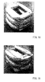
- An appearance of the test piece after compression is shown in pictures in FIG. 10 . Similar to the test piece No. 1, with regard to the test piece No. 2, a relationship between displacement and the compression load about the wood member contained in the test piece was obtained. Results are shown in FIGS. 11 and 12 .
- deformation configurations of the frame bodies contained in the test pieces may be different from each other although the wood members contained in the test pieces may undergo compression deformation without falling down.
- the frame body in the test piece No. 1, the frame body may be crashed while its wall surfaces adjacent to each other are folded alternately inward and outward. As a result, the frame body folded inward may bite into the wood member.
- the frame body in the test piece No. 2, the frame body may be crashed while its all circumferences are repeatedly deformed and bulged to spread outward. Further, in the test piece No. 2, the frame body may be crashed without protruding inward. That is, the frame body may not bite into the wood member.
- test pieces each of which is composed of only a hollow cylindrical frame body having a square shape in transverse cross section were prepared. Similar to Test 2, the test pieces were compressed in the same manner as Test 1, and deformation forms of the test pieces were observed. The test pieces after compression are shown in pictures in FIGS. 13-16 . Further, in Test 3, frame bodies A to D respectively formed by extrusion molding of aluminum (A5052) were used as the test pieces. Each of the frame bodies A-D was configured such that an outer side L in a hollow square cross-sectional surface and a length in an axial direction were respectively 20 mm and 70 mm. However, the frame bodies A-D were respectively configured to have different thicknesses. Sizes of each of the frame bodies are described in Table 2.
- the compression deformation forms of the frame bodies are also described in Table 2. Further, when the frame body was crashed while it is folded alternately inward and outward as the test piece No. 1 in Test 2, the compression deformation form thereof is labeled as "unsuitable” in Table 2. Instead, when the frame body was crashed while it is bulged outward only as the test piece No. 2 in Test 2, the deformation form thereof is labeled as "good” in Table 2. [Table 2] Test Piece. Thickness T (mm) Side L /Thickness T Compression Deformation Forms A 1.6 12.5 Unsuitable B 1.8 11.1 Good C 2.2 9.1 Good D 2.5 8.0 Unsuitable
- Test 4 similar to Test 3, hollow cylindrical frame bodies each having a square shape in transverse cross section were used as test pieces. Similar to Test 3, the test pieces were compressed, and deformation forms of the test pieces were observed. In Test 4, as described in Table 3, frame bodies E to K that are also different from each other in an outer side L in a hollow square cross-sectional surface and a length in an axial direction were used as the test pieces. In Test 4, the test pieces were respectively formed by extrusion molding of aluminum (A6063). Similar to Test 3, compression deformation forms of the test pieces are also described in Table 3.
- test pieces each having a rectangular shape in cross section were used as test pieces. Similar to Tests 3 and 4, the test pieces were compressed, and deformation forms of the test pieces were observed. Similar to Tests 3 and 4, the results of compression are also described in Table 4.
- the test pieces were respectively formed by extrusion molding of aluminum (A6063). Further, an outer short side and an outer long side described in Table 4 respectively mean lengths of an outer short side and an outer long side of a hollow rectangular cross-sectional surface.
- test pieces Nos. 3-8 of the impact-absorbing member were prepared according to Embodiment 3 or 4.
- Each test piece was composed of a wood member having a rounded shape in transverse cross section, and a hollow cylindrical frame body fitted around the wood member.
- a sawn cedar member was used as the wood member.
- an extrusion molded article of aluminum (A5052) was used as the frame body. Sizes of the test piece are described in Table 5. Further, a major axis a and a minor axis b shown in Table 5 may correspond to the sizes a and b shown in FIG. 7 .
- the test pieces Nos. 3-8 were compressed, and deformation forms of the test pieces were observed. The test pieces after compression are shown in pictures in FIGS.
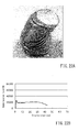
- test pieces Nos. 3-8 clearly show that when the test piece has a rounded shape in cross section, even if it is an elliptical shape other than a precise circular shape, the frame body can be crashed while its all circumferences are repeatedly deformed and bulged to spread outward regardless of the thickness of the frame body and can be prevented from protruding inward. Further, as shown in pictures in FIG. 22A , the test piece No. 5 having an elliptical shape in cross section and having a thin walled frame body may be diagonally crashed while an axis thereof is deflected. However, the frame body may be crashed while it is expanded outward without protruding inward and may not bite into the wood member.
- Tests 2-6 suggest that as the test piece changes from a rectangular shape toward a circular shape in cross section, the test piece may be likely to crash while it is expanded outward only regardless of the thickness of the frame body and flatness in cross section. Therefore, in subsequent Test 7, deformation forms were examined with regard to test pieces each having a polygonal shape closer to the circular shape than the rectangular shape in cross section.
- test pieces Nos. 9-12 of the impact-absorbing member each having a polygonal shape in cross section were prepared according to Embodiment 2.
- a sawn cedar member was used as a wood member.
- an extrusion molded article of aluminum (A5052) was used as a frame body. Shapes and sizes of the test piece are described in Table 6.
- the test pieces Nos. 9-12 were compressed, and deformation forms of the test pieces were observed.
- the compression deformation forms of the test pieces are additionally described in Table 6. In Table 6, when the frame body was crashed while it is bulged outward only, the deformation form thereof is labeled as "good.” [Table 6] Test Piece No.
- test pieces Nos. 9-12 clearly show that when the test piece has a regular hexagonal shape in cross section, the frame body can be crashed while its all circumferences are repeatedly deformed and bulged to spread outward regardless of the thickness thereof and can be prevented from protruding inward.
- the test piece No. 11 after compression are representatively shown in pictures in FIG. 26 .
- pictures in FIG. 27 it is recognized that when the test piece has a regular octagonal shape in cross section, the frame body can be crashed while its all circumferences are repeatedly deformed and bulged to spread outward and can be prevented from protruding inward.
- a regular N-polygonal shape in cross section satisfying N ⁇ 5 may preferably be used.
Landscapes
- Engineering & Computer Science (AREA)
- Mechanical Engineering (AREA)
- General Engineering & Computer Science (AREA)
- Body Structure For Vehicles (AREA)
- Vibration Dampers (AREA)
- Rod-Shaped Construction Members (AREA)
Abstract
Description
- The present invention relates to a vehicle impact-absorbing member. More particularly, the present invention relates to a vehicle impact-absorbing member having a columnar wood member and a hollow cylindrical metal frame body covering side-surfaces of the wood member and configured to axially receive a compression load caused by impact.
- Such a vehicle impact-absorbing member is taught, for example, by
JP 2001-182769A - When the impact-absorbing member manufactured in accordance with an embodiment described in the document is axially compressed, the frame body undergoes buckling distortion into a bellows-shape while it is largely folded alternately inward and outward. Further, the frame body folded inward may bite into the wood member, so that a deformation direction of fiber of the wood member may be locally inclined. The wood member may be basically porous. Further, the fiber of the wood member may generally be unidirectionally-aligned. Therefore, if a fiber direction of the wood member can be aligned with a compression direction such that the wood member can be linearly compressed in the fiber direction, it is expected that the wood member can exploit its innate characteristics at maximum by a simple structure where the wood member is fitted into the frame body, so as to increase absorption amount of impact energy.
- In one aspect of the present invention, a vehicle impact-absorbing member may have a columnar wood member and a hollow cylindrical metal frame body covering side-surfaces of the wood member and may be configured to axially receive a compression load caused by impact in the event of a collision in an axial direction of wood member. The frame body may have a square cylindrical shape. A ratio of an outer side in a hollow square cross-sectional surface of the frame body to a thickness of the frame body may be set to a range of 9-12. In another embodiment, the frame body may have a regular N-polygonal cylindrical shape satisfying N ≧ 5 or a regular circular cylindrical shape. A further embodiment, the frame body may have an elliptical cylindrical shape. A ratio of an inner major axis a to an inner minor axis b in a hollow elliptical cross-sectional surface of the frame body, i.e., a ratio a/b, is set to 3 or less.
-
-
FIG. 1 is a perspective view of a impact-absorbing member according to Embodiment 1. -
FIG. 2 is a sectional view taken along a line perpendicular to an axial direction of the impact-absorbing member ofFIG. 1 . -
FIG. 3A is a schematic sectional view taken along line III-III ofFIG. 1 , which view illustrates a deformation form of a frame body of the impact-absorbing member, in which a ratio of an outer side in a hollow square cross-sectional surface to a thickness is in a range of 9-12 according to Embodiment 1. -
FIG. 3B is a schematic sectional view, which view illustrates a deformation configuration of a frame body of the impact-absorbing member, in which a ratio of the outer side in the hollow square cross-sectional surface to the thickness is out of the range of 9-12. -
FIG. 4 is a perspective view of an impact-absorbing member according to Embodiment 2. -
FIG. 5 is a perspective view of an impact-absorbing member according to Embodiment 3. -
FIG. 6 is a perspective view of an impact-absorbing member according to Embodiment 4. -
FIG. 7 is a sectional view taken along a line perpendicular to an axial direction of the impact-absorbing member ofFIG. 6 . -
FIG. 8 is a graph illustrating a relationship between a displacement and a compression load, which is obtained from Test 1 with regard to a square cedar wood member. -
FIG. 9 is a graph illustrating a relationship between a displacement and a compression load, which is obtained from Test 2 with regard to a test piece No. 1 shown in Table 1. -
FIG. 10 is an appearance picture of the test piece No. 1 shown in Table 1, which is viewed obliquely after it is compressed in Test 2. -
FIG. 11 is a graph illustrating a relationship between a displacement and a compression load, which is obtained from Test 2 with regard to a test piece No. 2 shown in Table 1. -
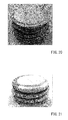
FIG. 12 is an appearance picture of the test piece No. 2 shown in Table 1, which is viewed obliquely after it is compressed in Test 2. -
FIG. 13 is an appearance picture of a frame body A shown in Table 2, which is viewed obliquely after it is compressed in Test 3. -
FIG. 14 is an appearance picture of a frame body B shown in Table 2, which is viewed obliquely after it is compressed in Test 3. -
FIG. 15 is an appearance picture of a frame body C shown in Table 2, which is viewed obliquely after it is compressed in Test 3. -
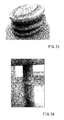
FIG. 16 is an appearance picture of a frame body D shown in Table 2, which is viewed obliquely after it is compressed in Test 3. -
FIG. 17 is an appearance picture of a frame body K shown in Table 3, which is viewed obliquely after it is compressed in Test 4. -
FIG. 18 is an appearance picture of a frame body S shown in Table 4, which is viewed obliquely after it is compressed inTest 5. -
FIG. 19 is an appearance picture of a frame body V shown in Table 4, which is viewed obliquely after it is compressed inTest 5. -
FIG. 20 is an appearance picture of a test piece No. 3 shown in Table 5, which is viewed obliquely after it is compressed in Test 6. -
FIG. 21 is an appearance picture of a test piece No. 4 shown in Table 5, which is viewed obliquely after it is compressed in Test 6. -
FIG. 22A is an appearance picture of a test piece No. 5 shown in Table 5, which is viewed obliquely after it is compressed in Test 6. -
FIG. 22B is a graph illustrating a relationship between a displacement and a compression load, which is obtained from Test 6 with regard to the test piece No. 5 shown in Table 5. -
FIG. 23 is an appearance picture of a test piece No. 6 shown in Table 5, which is viewed obliquely after it is compressed in Test 6. -
FIG. 24 is an appearance picture of a test piece No. 7 shown in Table 5, which is viewed obliquely after it is compressed in Test 6. -
FIG. 25 is an appearance picture of a test piece No. 8 shown in Table 5, which is viewed obliquely after it is compressed in Test 6. -
FIG. 26 is an appearance picture of a test piece No. 11 shown in Table 6, which is viewed obliquely after it is compressed in Test 7. -
FIG. 27 is an appearance picture of a test piece No. 12 shown in Table 6, which is viewed obliquely after it is compressed in Test 7. - An impact-absorbing member is a member that is attached to a vehicle such as an automobile in order to absorb impact energy generated in the event of a collision. A impact-absorbing member attaching position of the vehicle is not specially limited provided that the impact-absorbing member can absorb a collision energy in order to protect passengers, pedestrians or other such person. For example, the impact-absorbing member may be positioned between a fender panel and a body panel, between a bumper reinforcement member and a side member, between a door panel and a door trim, between a pillar and pillar trim, between a roof panel and a roof liner, and between a floor panel and a carpet. In the following, embodiments of the present invention will be described in detail with reference to the drawings.
- As shown in
FIG. 1 , an impact-absorbingmember 11 of the present embodiment may be composed of a rectangular columnar-shaped wood member 21 having a square shape in "cross section taken along a line perpendicular to an axial direction thereof" (which will be hereinafter simply referred to as "cross section"), and ametal frame body 31 covering side-surfaces of thewood member 21. The impact-absorbingmember 11 may be positioned so as to receive impact in the event of a collision in the axial direction of the rectangular column. - The
wood member 21 may be sawn up to a rectangular columnar shape such that a fiber direction thereof can be aligned parallel with a compression load (the axial direction). The type of thewood member 21 is not specially limited. For example, thewood member 21 can be formed by a needle leaf tree such as cedar, Japanese cypress and pine or a broad-leaf tree such as Japanese zelkova and beech. A wood member having high specific gravity may be characterized by superior strength. To the contrary, a wood member having low specific gravity may be characterized by an increased amount of compression deformation because of high porosity. Therefore, it is preferable to select a wood member having adequate specific gravity according to the impact-absorbing member attaching position of the vehicle in consideration of such a factor. A wood member having specific gravity of 0.2-0.4 can increase an absorption amount of the impact energy because such a wood member may have a sufficient amount of compression deformation and a certain level of strength. Therefore, such a wood member may be advantageously used. Examples of the wood member having specific gravity of 0.2-0.4 are cedar, Japanese cypress and pine. - The
frame body 31 may have a square cylindrical shape, i.e., a hollow cylindrical shape having a hollow square shape in "cross section taken along a line perpendicular to an axial direction thereof" (which will be hereinafter simply referred to as "cross section"). Theframe body 31 may support thewood member 21 and may function to be deformed with thewood member 21 due to the compression load in the axial direction. Theframe body 31 may preferably be made of aluminum, copper, iron or other such metals. Theframe body 31 may be closely fitted around thewood member 21 without clearance, so as to cover the entire side surfaces (the entire outer circumferential surface) of thewood member 21 in just proportion. - As shown in
FIG. 2 , a thickness T of theframe body 31 may substantially be uniform. Further, a ratio of an outer side L in a hollow square cross-sectional surface of theframe body 31 to the thickness T, i.e., a ratio L/T (which may be hereinafter referred to as a side to thickness ratio), may be set to a range of 9-12. - The impact-absorbing
member 11 may be positioned such that the axial direction (a fiber direction) of thewood member 21 can be aligned parallel with a collisional direction of the vehicle. When the impact-absorbingmember 11 is subjected to the compression load in the axial direction by the collision, theframe body 31 encircling thewood member 21 may be crashed in the axial direction while it is buckled. As a result, thewood member 21 may be prevented from falling down by theframe body 31, so as to directly undergo compression deformation in the axial direction. At this time, as schematically shown inFIG. 3A , theframe body 31 can undergo buckling distortion while it is repeatedly expanded outward only although the principle is not necessarily known. According to the impact-absorbingmember 11, when the compression load in the axial direction is applied thereto, theframe body 31 encircling thewood member 21 may be crashed without changing the axial direction thereof. Therefore, thewood member 21 can linearly undergo compression deformation in the fiber direction without falling down. At this time, theframe body 31 can be crashed while it is expanded outward without protruding inward. Therefore, theframe body 31 may be less likely to bite into thewood member 21. This allows thewood member 21 to exploit its innate characteristics at maximum. Further, when the frame body bites into the wood member, the wood member can be easily cracked because fiber of the wood member may be inclined. Also, deformation behavior of the wood member may be individually different. However, according to the impact-absorbing member of the present embodiment, theframe body 31 may be less likely to bite into thewood member 21. Therefore, the deformation behavior of the wood member can be prevented from being varied, so as to fall within a predictable range. Further, the impact-absorbing member may be less likely to produce change of a reactive force that can be produced when fiber of the wood member is partially inclined due to biting of the frame body into the wood member. Thus, the change of the reactive force can be minimized. As a result, variation of impact-absorbing performance can be minimized. - Further, when the ratio L/T of the side in the cross-sectional surface of the
frame body 31 to the thickness thereof is out of the range of 9-12, theframe body 31 can be crashed in the axial direction. However, as shown inFIG. 3B , theframe body 31 can be deformed into a bellows-shape while it is folded in both directions of inward and outward. Therefore, if thewood member 21 is closely fitted into theframe body 31 without clearance, theframe body 31 may be likely to bite into thewood member 21. To the contrary, in the impact-absorbingmember 11 of the present embodiment, as previously described, theframe body 31 can be crashed without protruding inward. Therefore, although there is no clearance between theframe body 31 and thewood member 21, theframe body 31 may be less likely to bite into thewood member 21. Naturally, in the present embodiment, theframe body 31 and thewood member 21 can be modified such that any clearance can be formed therebetween. Further, thewood member 21 may not necessarily have square columnar shape. However, it is preferable that thewood member 21 internally contacts theframe body 31 because thewood member 21 can be easily positioned with respect to theframe body 31. Further, it is more preferable that thewood member 21 is closely fitted into theframe body 31 without clearance. This is because strength of the impact-absorbingmember 11 can be effectively increased with respect to cross-sectional area thereof and an impact absorption amount thereof can be effectively increased. - As shown in
FIG. 4 , an impact-absorbingmember 12 of the present embodiment may be composed of a columnar-shapedwood member 22 having a regular N-polygonal shape in cross section satisfying N≧5, and ametal frame body 32 covering side-surfaces of thewood member 22. The impact-absorbingmember 12 may function to receive a compression load in an axial direction thereof. Further,FIG. 4 shows the impact-absorbingmember 12 having a regular hexagonal shape in cross section, i.e., a regular N-polygonal shape at N=6. Thewood member 22 and theframe body 32 may be made of the same material as thewood member 21 and theframe body 31 of Embodiment 1 described above and may be simply different therefrom in shape. - The
frame body 32 may have a regular N-polygonal cylindrical shape having the same N-number as thewood member 22, i.e., a hollow cylindrical shape having a hollow regular N-polygonal shape in cross section. Theframe body 32 is capable of supporting thewood member 22 and capable of deforming with thewood member 22 when the compression load in an axial direction is applied thereto. Theframe body 32 may be closely fitted around thewood member 22 without clearance, so as to cover the entire side surfaces of thewood member 22 in just proportion. A thickness of theframe body 32 may substantially be uniform and may be appropriately determined provided that theframe body 32 can be deformed with thewood member 22. The thickness of theframe body 32 can be determined without taking into account a balance against an outer size of thewood member 23. - When the compression load in the axial direction acts on the impact-absorbing
member 12, theframe body 32 can be crashed in the axial direction while it is repeatedly expanded outward only although the principle is not necessarily known. At the same time, thewood member 22 can directly undergo compression deformation in an axial direction while it is prevented from falling down by theframe body 32. According to the impact-absorbingmember 12, when the compression load in the axial direction is applied thereto, theframe body 32 encircling thewood member 21 may be crashed without changing the axial direction thereof. Therefore, thewood member 22 can linearly undergo compression deformation in the fiber direction without falling down. At this time, theframe body 32 can be crashed while it is expanded outward without protruding inward. Therefore, theframe body 32 may be less likely to bite into thewood member 22. This allows thewood member 22 to exploit its innate characteristics at maximum. Further, theframe body 32 and thewood member 22 may be less likely to interfere with each other. Therefore, the deformation behavior of the wood member can be prevented from being varied. Further, change of a reactive force can be minimized, so that variation of impact-absorbing performance can be minimized. - As shown in
FIG. 5 , an impact-absorbingmember 13 of the present embodiment may be composed of a columnar-shapedwood member 23 having a precise circular shape in cross section, and ametal frame body 33 covering side-surfaces of thewood member 23. The impact-absorbingmember 13 may function to receive a compression load in an axial direction thereof. Thewood member 23 and theframe body 33 may be made of the same material as thewood member 21 and theframe body 31 of Embodiment 1 described above and may be simply different therefrom in shape. - The
frame body 33 may have a precise cylindrical shape, i.e., a hollow cylindrical shape having a hollow precise circular shape in cross section. Theframe body 33 is capable of supporting thewood member 23 and capable of deforming with thewood member 23 when the compression load in an axial direction is applied thereto. Theframe body 33 may be closely fitted around thewood member 23 without clearance, so as to cover the entire side surfaces of thewood member 23 in just proportion. A thickness of theframe body 33 may substantially be uniform and may be appropriately determined such that theframe body 33 can be deformed with thewood member 23. Further, the thickness of theframe body 33 can be determined without taking into account a balance against an outer size of thewood member 23. - When the compression load in the axial direction acts on the impact-absorbing
member 13, theframe body 33 encircling thewood member 23 can be crashed in the axial direction while it is repeatedly expanded outward only, although the principle is not necessarily known. At the same time, thewood member 23 can directly undergo compression deformation in an axial direction while it is prevented from falling down by theframe body 33. According to the impact-absorbingmember 13, when the compression load in the axial direction is applied thereto, theframe body 33 encircling thewood member 23 may be crashed without changing the axial direction thereof. Therefore, thewood member 23 can linearly undergo compression deformation in the fiber direction without falling down. At this time, theframe body 33 can be crashed while it is folded outward without being folded inward. Therefore, theframe body 33 may be less likely to bite into thewood member 23. This allows thewood member 23 to exploit its innate characteristics at maximum. Further, theframe body 33 and thewood member 23 may be less likely to interfere with each other. Therefore, the deformation behavior of the wood member can be prevented from being varied. Further, change of a reactive force can be minimized, so that variation of impact-absorbing performance can be minimized. - As shown in
FIG. 6 , an impact-absorbingmember 14 of the present embodiment may be composed of a columnar-shapedwood member 24 having an elliptical shape in cross section, and ametal frame body 34 covering side-surfaces of thewood member 24. The impact-absorbingmember 14 may function to receive a compression load in an axial direction thereof. Thewood member 24 and theframe body 34 may be made of the same material as thewood member 21 and theframe body 31 of Embodiment 1 described above and may be simply different therefrom in shape. - The
frame body 34 may have an elliptical cylindrical shape, i.e., a hollow cylindrical shape having a hollow elliptical shape in cross section. A ratio of an inner major axis a to an inner minor axis b in a hollow elliptical cross-sectional surface of theframe body 34, i.e., a ratio a/b (which will be hereinafter referred to as a major axis to minor axis ratio), may be set to 3 or less (FIG. 7 ). Further, when the major axis to minor axis ratio is equal to 1, the cross-sectional surface may turn into a hollow precise circular shape. Therefore, more properly, the major axis to minor axis ratio may be set so as to satisfy 1<a/b≦3. Theframe body 34 is capable of supporting thewood member 24 and capable of deforming with thewood member 24 when the compression load in an axial direction is applied thereto. Theframe body 34 may be closely fitted around thewood member 24 without clearance, so as to cover the entire side surfaces of thewood member 24 in just proportion. A thickness of theframe body 34 may substantially be uniform and may be appropriately determined such that theframe body 34 can be deformed with thewood member 24. - When the compression load in the axial direction acts on the impact-absorbing
member 14, theframe body 34 encircling thewood member 24 can be crashed in the axial direction while it is repeatedly expanded outward only, although the principle is not necessarily known. At the same time, thewood member 24 can undergo compression deformation. At this time, theframe body 34 can be crashed while it is folded outward without being folded inward. Therefore, theframe body 34 may be less likely to bite into thewood member 24. This allows thewood member 24 to appropriately exploit its innate characteristics. Further, theframe body 34 and thewood member 24 may be less likely to interfere with each other. Therefore, the deformation behavior of the wood member can be prevented from being varied. Further, change of a reactive force can be minimized, so that variation of impact-absorbing performance can be minimized. - Test 1 was intended to determine innate impact-absorbing performance of a wood member. A square cedar wood member having a square shape in cross section (40 mm × 40 mm × 70 mm : a length in an axial direction) was prepared. The wood member was sawn up such that a fiber direction thereof can be aligned parallel with the axial direction (a compression direction). The wood member was set on a compression testing machine (Autograph AG-100KNE) manufactured by Shimazu Corporation while it is not encircled by a frame body. The wood member was compressed in the axial direction under conditions of 2 mm/min, and a relationship between displacement (an amount of compression) and a compression load (i.e., a reactive force produced by an impact-absorbing member) was measured. Results are shown in
FIG. 8 . - As will be apparent from
FIG. 8 , when the wood member is compressed in the fiber direction thereof, the compression load may continue to be extremely stable. This demonstrates that the wood member may have high impact-absorbing performance. - In Test 2, test pieces Nos. 1 and 2 of the impact-absorbing member were prepared according to Embodiment 1. Each test piece was composed of a wood member having a square shape in cross section, and a hollow cylindrical frame body fitted around the wood member. A square cedar member was used as the wood member. Further, an extrusion molded article of aluminum (A5052) was used as the frame body. Sizes of each test piece are described in Table 1. Further, an outer side L in a hollow square cross-sectional surface and a thickness T of the frame body shown in Table 1 may correspond to the sizes L and T shown in
FIG. 2 .[Table 1] Test Piece No. Outer Side L in Hollow Square Cross-Sectional Surface (mm) Thickness T of Frame Body (mm) Length in Axial Direction (mm) Side L /Thickness T 1 16 0.5 50 32 2 15 1.5 50 10 - Next, the test piece No. 1 was compressed in the axial direction in the same manner as Test 1, and a relationship between displacement and a compression load was measured. In addition, only the frame body was similarly compressed, and a relationship between displacement and a compression load was measured. Thereafter, a result obtained about only the frame body was subtracted from a result obtained about the test piece in which the frame body was fitted around the wood member, so as to obtain a relationship between displacement and the compression load about only the wood member contained in the test piece. Results are shown in
FIG. 9 . An appearance of the test piece after compression is shown in pictures inFIG. 10 . Similar to the test piece No. 1, with regard to the test piece No. 2, a relationship between displacement and the compression load about the wood member contained in the test piece was obtained. Results are shown inFIGS. 11 and12 . - As will be apparent by comparing graphs shown in
FIGS. 9 and11 each of which shows a relationship between displacement and the compression load about the wood member contained in the test piece, in the test piece No. 2 in which the ratio L/T of the side in the cross-sectional surface to the thickness is 10, change of the compression load may be quite small in comparison with the test piece No. 1 in which the ratio L/T of the side in the cross-sectional surface to the thickness is 20. Further, similar to the results of Test 1 in which only the wood member is compressed, the compression load of the wood member contained in the test piece No. 2 may be stable. Next, in view of deformation forms of the test pieces, deformation configurations of the frame bodies contained in the test pieces may be different from each other although the wood members contained in the test pieces may undergo compression deformation without falling down. As shown in pictures inFIG. 10 , in the test piece No. 1, the frame body may be crashed while its wall surfaces adjacent to each other are folded alternately inward and outward. As a result, the frame body folded inward may bite into the wood member. To the contrary, as shown in pictures inFIG. 12 , in the test piece No. 2, the frame body may be crashed while its all circumferences are repeatedly deformed and bulged to spread outward. Further, in the test piece No. 2, the frame body may be crashed without protruding inward. That is, the frame body may not bite into the wood member. The results clearly show that in the test piece having a square shape in cross section, only when the ratio L/T of the side in the cross-sectional surface to the thickness has a particular value, the frame body can be compressed while it is bulged outward only, so as to be prevented from biting into the wood member. This means that the wood member can appropriately exploit its innate characteristics so as to stabilize the compression load. - In Test 3, test pieces each of which is composed of only a hollow cylindrical frame body having a square shape in transverse cross section were prepared. Similar to Test 2, the test pieces were compressed in the same manner as Test 1, and deformation forms of the test pieces were observed. The test pieces after compression are shown in pictures in
FIGS. 13-16 . Further, in Test 3, frame bodies A to D respectively formed by extrusion molding of aluminum (A5052) were used as the test pieces. Each of the frame bodies A-D was configured such that an outer side L in a hollow square cross-sectional surface and a length in an axial direction were respectively 20 mm and 70 mm. However, the frame bodies A-D were respectively configured to have different thicknesses. Sizes of each of the frame bodies are described in Table 2. Further, the compression deformation forms of the frame bodies are also described in Table 2. Further, when the frame body was crashed while it is folded alternately inward and outward as the test piece No. 1 in Test 2, the compression deformation form thereof is labeled as "unsuitable" in Table 2. Instead, when the frame body was crashed while it is bulged outward only as the test piece No. 2 in Test 2, the deformation form thereof is labeled as "good" in Table 2.[Table 2] Test Piece. Thickness T (mm) Side L /Thickness T Compression Deformation Forms A 1.6 12.5 Unsuitable B 1.8 11.1 Good C 2.2 9.1 Good D 2.5 8.0 Unsuitable - The results described in Table 2 clearly show that when the ratio L/T of the side in the cross-sectional surface of the frame body to the thickness is set to a range of 9-12, the frame body may be crashed while its all circumferences are repeatedly deformed and bulged to spread outward and can be prevented from protruding inward (
FIGS. 14 and 15 ). Conversely, the results show that when the ratio L/T of the side in the cross-sectional surface of the frame body to the thickness is out of the range of 9-12, the frame body may be crashed while its wall surfaces adjacent to each other are folded alternately inward and outward and a portion of the frame body may protrude inward (FIGS. 13 and16 ). - In Test 4, similar to Test 3, hollow cylindrical frame bodies each having a square shape in transverse cross section were used as test pieces. Similar to Test 3, the test pieces were compressed, and deformation forms of the test pieces were observed. In Test 4, as described in Table 3, frame bodies E to K that are also different from each other in an outer side L in a hollow square cross-sectional surface and a length in an axial direction were used as the test pieces. In Test 4, the test pieces were respectively formed by extrusion molding of aluminum (A6063). Similar to Test 3, compression deformation forms of the test pieces are also described in Table 3.
[Table 3] Test Piece Outer Side L in Hollow Square Cross-Sectional Surface (mm) Thickness T (mm) Length in Axial Direction (mm) Side L /Thickness T Compression Deformation Forms E 10 0.9 20 11.1 Good F 10 0.9 40 11.1 Good G 15 1.4 20 10.7 Good H 15 1.4 40 10.7 Good I 25 2.4 40 10.4 Good J 25 2.4 60 10.4 Good K 25 2.4 80 10.4 Good ( FIG.17 ) - The results described in Table 3 demonstrate that even when the outer side L in a hollow square cross-sectional surface and the length in an axial direction are changed, the frame body may be crashed while its all circumferences are repeatedly deformed and bulged to spread outward and may not protrude inward provided that the ratio L/T of the side in the cross-sectional surface to the thickness is in the range of 9-12. The frame body K after compression is representatively shown in pictures in
FIG. 17 . - In
Test 5, as described in Table 4, hollow cylindrical frame bodies each having a rectangular shape in cross section were used as test pieces. Similar to Tests 3 and 4, the test pieces were compressed, and deformation forms of the test pieces were observed. Similar to Tests 3 and 4, the results of compression are also described in Table 4. InTest 5, the test pieces were respectively formed by extrusion molding of aluminum (A6063). Further, an outer short side and an outer long side described in Table 4 respectively mean lengths of an outer short side and an outer long side of a hollow rectangular cross-sectional surface.[Table 4] Test Piece Outer Short Side (mm) Outer Long Side (mm) Length in Axial Direction (mm) Thickness (mm) Short Side /Thickness Long Side /Thickness Compression Deformation Forms L 10 15 20 1.00 10.0 15.0 Unsuitable M 10 15 40 1.00 10.0 15.0 Unsuitable N 15 30 20 1.50 10.0 15.0 Unsuitable O 15 30 40 1.50 10.0 20.0 Unsuitable P 15 30 60 1.50 10.0 20.0 Unsuitable Q 20 30 40 1.85 10.8 16.2 Unsuitable R 20 30 60 1.85 10.8 16.2 Unsuitable S 20 30 80 1.85 10.8 16.2 Unsuitable ( FIG. 18 )T 20 40 40 1.85 10.8 21.6 Unsuitable U 20 40 60 1.85 10.8 21.6 Unsuitable V 20 40 80 1.85 10.8 21.6 Unsuitable ( FIG. 19 ) - As will be apparent from Table 4, in
Test 5, even when a ratio of an outer short side in the rectangular cross-sectional surface of the frame body to a thickness (a short side to thickness ratio) is in the range of 9-12, the frame body may be crashed while it is folded alternately inward and outward and not while it is bulged outward only. The frame bodies S and V after compression are representatively shown in pictures inFIGS. 18 and 19 . The results clearly show that when the frame body has a rectangular shape in cross section, in particular, when the frame body has a square shape in cross section, the frame body can be crashed while it is bulged outward only by setting the short side to thickness ratio to 9-12. - In Test 6, test pieces Nos. 3-8 of the impact-absorbing member were prepared according to Embodiment 3 or 4. Each test piece was composed of a wood member having a rounded shape in transverse cross section, and a hollow cylindrical frame body fitted around the wood member. A sawn cedar member was used as the wood member. Further, an extrusion molded article of aluminum (A5052) was used as the frame body. Sizes of the test piece are described in Table 5. Further, a major axis a and a minor axis b shown in Table 5 may correspond to the sizes a and b shown in
FIG. 7 . Next, similar to Test 2, the test pieces Nos. 3-8 were compressed, and deformation forms of the test pieces were observed. The test pieces after compression are shown in pictures inFIGS. 20-25 . Further, the compression deformation forms of the test pieces are also described in Table 5. In Table 5, when the frame body was crashed while it is bulged outward only, the deformation form thereof is labeled as "good." Further, when the deformation form is not good, it is annotated.[Table 5] Test Piece No. Shape in Cross Section Major Axis (mm) Minor Axis (mm) Thickness of Frame Body (mm) Major Axis a /Minor Axis b Compression Deformation Forms 3 Precise Circle 40 40 0.5 1 Good 4 Precise Circle 40 40 2.0 1 Good 5 Ellipse 40 20 0.5 2 Good 6 Ellipse 40 20 2.0 2 Good 7 Ellipse 40 10 0.5 4 [1] 8 Ellipse 40 10 2.0 4 [2] [1]: The frame body was crashed while it is folded inward and outward. Finally, the whole impact-absorbing member was buckled.
[2]: The whole impact-absorbing member was buckled. - The results of the test pieces Nos. 3-8 clearly show that when the test piece has a rounded shape in cross section, even if it is an elliptical shape other than a precise circular shape, the frame body can be crashed while its all circumferences are repeatedly deformed and bulged to spread outward regardless of the thickness of the frame body and can be prevented from protruding inward. Further, as shown in pictures in
FIG. 22A , the test piece No. 5 having an elliptical shape in cross section and having a thin walled frame body may be diagonally crashed while an axis thereof is deflected. However, the frame body may be crashed while it is expanded outward without protruding inward and may not bite into the wood member. As a result, fiber of the wood member may not be randomly inclined. As shown by a graph inFIG. 22B , a compression load may continue to be stable. Further, the results of the test pieces Nos. 5-8 clearly show that when the test piece has an elliptical shape in cross section, the whole test piece may be likely to buckle as an ellipse is excessively flattened. This demonstrates that a ratio a/b of the major axis to the minor axis in an elliptical cross-sectional surface may preferably be set to 3 or less. - The results of Tests 2-6 suggest that as the test piece changes from a rectangular shape toward a circular shape in cross section, the test piece may be likely to crash while it is expanded outward only regardless of the thickness of the frame body and flatness in cross section. Therefore, in subsequent Test 7, deformation forms were examined with regard to test pieces each having a polygonal shape closer to the circular shape than the rectangular shape in cross section.
- In Test 7, test pieces Nos. 9-12 of the impact-absorbing member each having a polygonal shape in cross section were prepared according to Embodiment 2. A sawn cedar member was used as a wood member. Further, an extrusion molded article of aluminum (A5052) was used as a frame body. Shapes and sizes of the test piece are described in Table 6. Next, similar to Test 7, the test pieces Nos. 9-12 were compressed, and deformation forms of the test pieces were observed. The compression deformation forms of the test pieces are additionally described in Table 6. In Table 6, when the frame body was crashed while it is bulged outward only, the deformation form thereof is labeled as "good."
[Table 6] Test Piece No. Shape in Cross Section Outer Side [1] (mm) Thickness of Frame Body (mm) Length in Axial Direction (mm) Compression Deformation Forms 9 Regular Hexagon 16 0.5 70 Good 10 Regular Hexagon 16 1.0 70 Good 11 Regular Hexagon 16 1.6 70 Good ( FIG. 26 )12 Regular Octagon 12 1.2 70 Good ( FIG. 27 )[1]: A length of an outer side in a hollow regular polygonal cross-sectional surface. - The results of the test pieces Nos. 9-12 clearly show that when the test piece has a regular hexagonal shape in cross section, the frame body can be crashed while its all circumferences are repeatedly deformed and bulged to spread outward regardless of the thickness thereof and can be prevented from protruding inward. The test piece No. 11 after compression are representatively shown in pictures in
FIG. 26 . Also, as shown in pictures inFIG. 27 , it is recognized that when the test piece has a regular octagonal shape in cross section, the frame body can be crashed while its all circumferences are repeatedly deformed and bulged to spread outward and can be prevented from protruding inward. This demonstrates that a regular N-polygonal shape in cross section satisfying N≧5 may preferably be used.
Claims (3)
- A vehicle impact-absorbing member having a columnar wood member and a hollow cylindrical metal frame body covering side-surfaces of the wood member and configured to axially receive a compression load caused by impact in the event of a collision in an axial direction of wood member,
wherein the frame body has a square cylindrical shape, and wherein a ratio of an outer side in a hollow square cross-sectional surface of the frame body to a thickness of the frame body is set to a range of 9-12. - A vehicle impact-absorbing member having a columnar wood member and a hollow cylindrical metal frame body covering side-surfaces of the wood member and configured to axially receive a compression load caused by impact in the event of a collision in an axial direction of wood member,
wherein the frame body has a regular N-polygonal cylindrical shape satisfying N≧5 or a regular circular cylindrical shape. - A vehicle impact-absorbing member having a columnar wood member and a hollow cylindrical metal frame body covering side-surfaces of the wood member and configured to axially receive a compression load caused by impact in the event of a collision in an axial direction of wood member,
wherein the frame body has an elliptical cylindrical shape, and wherein a ratio of an inner major axis a to an inner minor axis b in a hollow elliptical cross-sectional surface of the frame body, i.e., a ratio a/b, is set to 3 or less.
Applications Claiming Priority (2)
| Application Number | Priority Date | Filing Date | Title |
|---|---|---|---|
| JP2011283389A JP5776537B2 (en) | 2011-12-26 | 2011-12-26 | Shock absorber for vehicle |
| PCT/JP2012/081520 WO2013099542A1 (en) | 2011-12-26 | 2012-12-05 | Vehicle shock absorption member |
Publications (3)
| Publication Number | Publication Date |
|---|---|
| EP2799289A1 true EP2799289A1 (en) | 2014-11-05 |
| EP2799289A4 EP2799289A4 (en) | 2015-08-05 |
| EP2799289B1 EP2799289B1 (en) | 2018-08-08 |
Family
ID=48697039
Family Applications (1)
| Application Number | Title | Priority Date | Filing Date |
|---|---|---|---|
| EP12862992.0A Active EP2799289B1 (en) | 2011-12-26 | 2012-12-05 | Vehicle shock absorption member |
Country Status (4)
| Country | Link |
|---|---|
| US (1) | US9221413B2 (en) |
| EP (1) | EP2799289B1 (en) |
| JP (1) | JP5776537B2 (en) |
| WO (1) | WO2013099542A1 (en) |
Cited By (2)
| Publication number | Priority date | Publication date | Assignee | Title |
|---|---|---|---|---|
| CN109774634A (en) * | 2017-11-15 | 2019-05-21 | 丰田车体株式会社 | Vehicular impact absorption component |
| WO2020053623A1 (en) * | 2018-09-11 | 2020-03-19 | Arcelormittal | Energy absorbing device, motor vehicle body and method for manufacturing thereof |
Families Citing this family (10)
| Publication number | Priority date | Publication date | Assignee | Title |
|---|---|---|---|---|
| EP2786903B1 (en) * | 2011-11-29 | 2018-03-14 | Toyota Shatai Kabushiki Kaisha | Shock-absorbing member for vehicle |
| JP5791676B2 (en) * | 2013-09-10 | 2015-10-07 | 富士重工業株式会社 | Shock absorber |
| JP6393921B2 (en) * | 2013-11-20 | 2018-09-26 | 藤森工業株式会社 | Adhesive composition and surface protective film |
| JP6560568B2 (en) * | 2015-09-07 | 2019-08-14 | 株式会社Subaru | Energy absorbing structure |
| JP6558316B2 (en) * | 2016-07-05 | 2019-08-14 | 株式会社豊田自動織機 | Load energy absorber |
| JP6798457B2 (en) * | 2017-09-15 | 2020-12-09 | トヨタ自動車株式会社 | Vampari Information |
| JP6863219B2 (en) * | 2017-10-13 | 2021-04-21 | トヨタ自動車株式会社 | Vehicle side structure |
| JP2019217850A (en) * | 2018-06-18 | 2019-12-26 | トヨタ自動車株式会社 | Vehicle lateral structure |
| JP7125826B2 (en) * | 2019-02-18 | 2022-08-25 | トヨタ車体株式会社 | Impact absorbing member and manufacturing method thereof |
| JP7556822B2 (en) * | 2021-04-27 | 2024-09-26 | 株式会社豊田中央研究所 | Shock absorbing mechanism, and method for manufacturing shock absorbing mechanism |
Family Cites Families (11)
| Publication number | Priority date | Publication date | Assignee | Title |
|---|---|---|---|---|
| JPS5818853A (en) | 1981-07-24 | 1983-02-03 | Hitachi Ltd | Charged-particle applied device |
| JPS5818853U (en) * | 1981-07-30 | 1983-02-05 | 三菱自動車工業株式会社 | Automobile bumper mounting structure |
| JP2001182769A (en) * | 1999-12-27 | 2001-07-06 | Showa Alum Corp | Shock absorbing member |
| JP4150286B2 (en) | 2003-04-22 | 2008-09-17 | 三菱アルミニウム株式会社 | Body energy absorption structure |
| CA2542367A1 (en) | 2003-10-17 | 2005-04-28 | Shiina Kasei Co. | Method for producing plastic foamed composite |
| JP5545259B2 (en) * | 2010-12-01 | 2014-07-09 | トヨタ車体株式会社 | Shock absorbing member |
| JP2012218712A (en) * | 2011-04-14 | 2012-11-12 | Toyota Auto Body Co Ltd | Impact absorbing member |
| JP5522114B2 (en) * | 2011-04-26 | 2014-06-18 | トヨタ車体株式会社 | Shock absorbing member |
| US20140312541A1 (en) * | 2011-09-06 | 2014-10-23 | Dl Manufacturing | Loading dock bumper assembly |
| EP2786903B1 (en) * | 2011-11-29 | 2018-03-14 | Toyota Shatai Kabushiki Kaisha | Shock-absorbing member for vehicle |
| CA2845837A1 (en) * | 2013-03-12 | 2014-09-12 | Dl Manufacturing | Loading dock bumper assembly |
-
2011
- 2011-12-26 JP JP2011283389A patent/JP5776537B2/en active Active
-
2012
- 2012-12-05 US US14/368,482 patent/US9221413B2/en active Active
- 2012-12-05 WO PCT/JP2012/081520 patent/WO2013099542A1/en not_active Ceased
- 2012-12-05 EP EP12862992.0A patent/EP2799289B1/en active Active
Cited By (4)
| Publication number | Priority date | Publication date | Assignee | Title |
|---|---|---|---|---|
| CN109774634A (en) * | 2017-11-15 | 2019-05-21 | 丰田车体株式会社 | Vehicular impact absorption component |
| CN109774634B (en) * | 2017-11-15 | 2022-06-07 | 丰田车体株式会社 | Vehicle impact absorbing member |
| WO2020053623A1 (en) * | 2018-09-11 | 2020-03-19 | Arcelormittal | Energy absorbing device, motor vehicle body and method for manufacturing thereof |
| US11801800B2 (en) | 2018-09-11 | 2023-10-31 | Arcelormittal | Energy absorbing device, motor vehicle body and method for manufacturing thereof |
Also Published As
| Publication number | Publication date |
|---|---|
| JP5776537B2 (en) | 2015-09-09 |
| US20140346789A1 (en) | 2014-11-27 |
| EP2799289A4 (en) | 2015-08-05 |
| EP2799289B1 (en) | 2018-08-08 |
| JP2013132943A (en) | 2013-07-08 |
| WO2013099542A1 (en) | 2013-07-04 |
| US9221413B2 (en) | 2015-12-29 |
Similar Documents
| Publication | Publication Date | Title |
|---|---|---|
| EP2799289B1 (en) | Vehicle shock absorption member | |
| JP6510982B2 (en) | Shock absorbing element | |
| EP2985211A1 (en) | Reinforced body in white and method of making and using the same | |
| US20150307049A1 (en) | Shock absorbing auxiliary member for absorbing shock in head lining of vehicle | |
| CN107848477A (en) | Bumper beam | |
| CN1918019A (en) | Impact absorbing device of vehicle | |
| EP2786903B1 (en) | Shock-absorbing member for vehicle | |
| JPWO2005010396A1 (en) | Shock absorbing member | |
| US20150274101A1 (en) | Bumper reinforcement | |
| US10640067B2 (en) | Vehicular impact-absorbing member | |
| JP2001182769A (en) | Shock absorbing member | |
| EP1800961B1 (en) | Shock absorbing material and vehicle bumper | |
| US20080217936A1 (en) | Bumper absorber | |
| US9016766B2 (en) | Energy dissipation system for vehicles | |
| JP5049153B2 (en) | Energy absorbing member and energy absorbing structure | |
| JP2001124128A (en) | Polygonal hollow material for shock absorption | |
| US8177044B2 (en) | Automotive impact absorbing member | |
| JP7777510B2 (en) | Automotive seat back frame | |
| CN102858597B (en) | There is the Plastic vehicle inner-decoration component clashing into module | |
| JP2009096225A (en) | Energy absorbing member | |
| US11981268B2 (en) | Energy absorbing material for a vehicle | |
| US9266486B2 (en) | Impact absorbing structure | |
| JPH06227333A (en) | Bumper unit | |
| JP2017170967A (en) | Impact absorber | |
| JPH05238338A (en) | Support bracket for knee panel |
Legal Events
| Date | Code | Title | Description |
|---|---|---|---|
| PUAI | Public reference made under article 153(3) epc to a published international application that has entered the european phase |
Free format text: ORIGINAL CODE: 0009012 |
|
| 17P | Request for examination filed |
Effective date: 20140702 |
|
| AK | Designated contracting states |
Kind code of ref document: A1 Designated state(s): AL AT BE BG CH CY CZ DE DK EE ES FI FR GB GR HR HU IE IS IT LI LT LU LV MC MK MT NL NO PL PT RO RS SE SI SK SM TR |
|
| DAX | Request for extension of the european patent (deleted) | ||
| RA4 | Supplementary search report drawn up and despatched (corrected) |
Effective date: 20150703 |
|
| RIC1 | Information provided on ipc code assigned before grant |
Ipc: B60R 19/34 20060101ALI20150629BHEP Ipc: B60R 19/24 20060101AFI20150629BHEP |
|
| STAA | Information on the status of an ep patent application or granted ep patent |
Free format text: STATUS: EXAMINATION IS IN PROGRESS |
|
| 17Q | First examination report despatched |
Effective date: 20170824 |
|
| GRAP | Despatch of communication of intention to grant a patent |
Free format text: ORIGINAL CODE: EPIDOSNIGR1 |
|
| STAA | Information on the status of an ep patent application or granted ep patent |
Free format text: STATUS: GRANT OF PATENT IS INTENDED |
|
| INTG | Intention to grant announced |
Effective date: 20180326 |
|
| GRAS | Grant fee paid |
Free format text: ORIGINAL CODE: EPIDOSNIGR3 |
|
| GRAA | (expected) grant |
Free format text: ORIGINAL CODE: 0009210 |
|
| STAA | Information on the status of an ep patent application or granted ep patent |
Free format text: STATUS: THE PATENT HAS BEEN GRANTED |
|
| AK | Designated contracting states |
Kind code of ref document: B1 Designated state(s): AL AT BE BG CH CY CZ DE DK EE ES FI FR GB GR HR HU IE IS IT LI LT LU LV MC MK MT NL NO PL PT RO RS SE SI SK SM TR |
|
| REG | Reference to a national code |
Ref country code: GB Ref legal event code: FG4D |
|
| REG | Reference to a national code |
Ref country code: CH Ref legal event code: EP Ref country code: AT Ref legal event code: REF Ref document number: 1026619 Country of ref document: AT Kind code of ref document: T Effective date: 20180815 |
|
| REG | Reference to a national code |
Ref country code: IE Ref legal event code: FG4D |
|
| REG | Reference to a national code |
Ref country code: DE Ref legal event code: R096 Ref document number: 602012049657 Country of ref document: DE |
|
| REG | Reference to a national code |
Ref country code: NL Ref legal event code: MP Effective date: 20180808 |
|
| REG | Reference to a national code |
Ref country code: LT Ref legal event code: MG4D |
|
| REG | Reference to a national code |
Ref country code: AT Ref legal event code: MK05 Ref document number: 1026619 Country of ref document: AT Kind code of ref document: T Effective date: 20180808 |
|
| PG25 | Lapsed in a contracting state [announced via postgrant information from national office to epo] |
Ref country code: FI Free format text: LAPSE BECAUSE OF FAILURE TO SUBMIT A TRANSLATION OF THE DESCRIPTION OR TO PAY THE FEE WITHIN THE PRESCRIBED TIME-LIMIT Effective date: 20180808 Ref country code: LT Free format text: LAPSE BECAUSE OF FAILURE TO SUBMIT A TRANSLATION OF THE DESCRIPTION OR TO PAY THE FEE WITHIN THE PRESCRIBED TIME-LIMIT Effective date: 20180808 Ref country code: PL Free format text: LAPSE BECAUSE OF FAILURE TO SUBMIT A TRANSLATION OF THE DESCRIPTION OR TO PAY THE FEE WITHIN THE PRESCRIBED TIME-LIMIT Effective date: 20180808 Ref country code: RS Free format text: LAPSE BECAUSE OF FAILURE TO SUBMIT A TRANSLATION OF THE DESCRIPTION OR TO PAY THE FEE WITHIN THE PRESCRIBED TIME-LIMIT Effective date: 20180808 Ref country code: SE Free format text: LAPSE BECAUSE OF FAILURE TO SUBMIT A TRANSLATION OF THE DESCRIPTION OR TO PAY THE FEE WITHIN THE PRESCRIBED TIME-LIMIT Effective date: 20180808 Ref country code: NO Free format text: LAPSE BECAUSE OF FAILURE TO SUBMIT A TRANSLATION OF THE DESCRIPTION OR TO PAY THE FEE WITHIN THE PRESCRIBED TIME-LIMIT Effective date: 20181108 Ref country code: GR Free format text: LAPSE BECAUSE OF FAILURE TO SUBMIT A TRANSLATION OF THE DESCRIPTION OR TO PAY THE FEE WITHIN THE PRESCRIBED TIME-LIMIT Effective date: 20181109 Ref country code: IS Free format text: LAPSE BECAUSE OF FAILURE TO SUBMIT A TRANSLATION OF THE DESCRIPTION OR TO PAY THE FEE WITHIN THE PRESCRIBED TIME-LIMIT Effective date: 20181208 Ref country code: NL Free format text: LAPSE BECAUSE OF FAILURE TO SUBMIT A TRANSLATION OF THE DESCRIPTION OR TO PAY THE FEE WITHIN THE PRESCRIBED TIME-LIMIT Effective date: 20180808 Ref country code: AT Free format text: LAPSE BECAUSE OF FAILURE TO SUBMIT A TRANSLATION OF THE DESCRIPTION OR TO PAY THE FEE WITHIN THE PRESCRIBED TIME-LIMIT Effective date: 20180808 Ref country code: BG Free format text: LAPSE BECAUSE OF FAILURE TO SUBMIT A TRANSLATION OF THE DESCRIPTION OR TO PAY THE FEE WITHIN THE PRESCRIBED TIME-LIMIT Effective date: 20181108 |
|
| PG25 | Lapsed in a contracting state [announced via postgrant information from national office to epo] |
Ref country code: LV Free format text: LAPSE BECAUSE OF FAILURE TO SUBMIT A TRANSLATION OF THE DESCRIPTION OR TO PAY THE FEE WITHIN THE PRESCRIBED TIME-LIMIT Effective date: 20180808 Ref country code: HR Free format text: LAPSE BECAUSE OF FAILURE TO SUBMIT A TRANSLATION OF THE DESCRIPTION OR TO PAY THE FEE WITHIN THE PRESCRIBED TIME-LIMIT Effective date: 20180808 Ref country code: AL Free format text: LAPSE BECAUSE OF FAILURE TO SUBMIT A TRANSLATION OF THE DESCRIPTION OR TO PAY THE FEE WITHIN THE PRESCRIBED TIME-LIMIT Effective date: 20180808 |
|
| PG25 | Lapsed in a contracting state [announced via postgrant information from national office to epo] |
Ref country code: IT Free format text: LAPSE BECAUSE OF FAILURE TO SUBMIT A TRANSLATION OF THE DESCRIPTION OR TO PAY THE FEE WITHIN THE PRESCRIBED TIME-LIMIT Effective date: 20180808 Ref country code: ES Free format text: LAPSE BECAUSE OF FAILURE TO SUBMIT A TRANSLATION OF THE DESCRIPTION OR TO PAY THE FEE WITHIN THE PRESCRIBED TIME-LIMIT Effective date: 20180808 Ref country code: CZ Free format text: LAPSE BECAUSE OF FAILURE TO SUBMIT A TRANSLATION OF THE DESCRIPTION OR TO PAY THE FEE WITHIN THE PRESCRIBED TIME-LIMIT Effective date: 20180808 Ref country code: RO Free format text: LAPSE BECAUSE OF FAILURE TO SUBMIT A TRANSLATION OF THE DESCRIPTION OR TO PAY THE FEE WITHIN THE PRESCRIBED TIME-LIMIT Effective date: 20180808 Ref country code: EE Free format text: LAPSE BECAUSE OF FAILURE TO SUBMIT A TRANSLATION OF THE DESCRIPTION OR TO PAY THE FEE WITHIN THE PRESCRIBED TIME-LIMIT Effective date: 20180808 |
|
| REG | Reference to a national code |
Ref country code: DE Ref legal event code: R097 Ref document number: 602012049657 Country of ref document: DE |
|
| PG25 | Lapsed in a contracting state [announced via postgrant information from national office to epo] |
Ref country code: DK Free format text: LAPSE BECAUSE OF FAILURE TO SUBMIT A TRANSLATION OF THE DESCRIPTION OR TO PAY THE FEE WITHIN THE PRESCRIBED TIME-LIMIT Effective date: 20180808 Ref country code: SK Free format text: LAPSE BECAUSE OF FAILURE TO SUBMIT A TRANSLATION OF THE DESCRIPTION OR TO PAY THE FEE WITHIN THE PRESCRIBED TIME-LIMIT Effective date: 20180808 Ref country code: SM Free format text: LAPSE BECAUSE OF FAILURE TO SUBMIT A TRANSLATION OF THE DESCRIPTION OR TO PAY THE FEE WITHIN THE PRESCRIBED TIME-LIMIT Effective date: 20180808 |
|
| PLBE | No opposition filed within time limit |
Free format text: ORIGINAL CODE: 0009261 |
|
| STAA | Information on the status of an ep patent application or granted ep patent |
Free format text: STATUS: NO OPPOSITION FILED WITHIN TIME LIMIT |
|
| 26N | No opposition filed |
Effective date: 20190509 |
|
| REG | Reference to a national code |
Ref country code: CH Ref legal event code: PL |
|
| GBPC | Gb: european patent ceased through non-payment of renewal fee |
Effective date: 20181205 |
|
| PG25 | Lapsed in a contracting state [announced via postgrant information from national office to epo] |
Ref country code: SI Free format text: LAPSE BECAUSE OF FAILURE TO SUBMIT A TRANSLATION OF THE DESCRIPTION OR TO PAY THE FEE WITHIN THE PRESCRIBED TIME-LIMIT Effective date: 20180808 Ref country code: LU Free format text: LAPSE BECAUSE OF NON-PAYMENT OF DUE FEES Effective date: 20181205 Ref country code: MC Free format text: LAPSE BECAUSE OF FAILURE TO SUBMIT A TRANSLATION OF THE DESCRIPTION OR TO PAY THE FEE WITHIN THE PRESCRIBED TIME-LIMIT Effective date: 20180808 |
|
| REG | Reference to a national code |
Ref country code: IE Ref legal event code: MM4A |
|
| REG | Reference to a national code |
Ref country code: BE Ref legal event code: MM Effective date: 20181231 |
|
| PG25 | Lapsed in a contracting state [announced via postgrant information from national office to epo] |
Ref country code: IE Free format text: LAPSE BECAUSE OF NON-PAYMENT OF DUE FEES Effective date: 20181205 Ref country code: FR Free format text: LAPSE BECAUSE OF NON-PAYMENT OF DUE FEES Effective date: 20181231 |
|
| PG25 | Lapsed in a contracting state [announced via postgrant information from national office to epo] |
Ref country code: BE Free format text: LAPSE BECAUSE OF NON-PAYMENT OF DUE FEES Effective date: 20181231 |
|
| PG25 | Lapsed in a contracting state [announced via postgrant information from national office to epo] |
Ref country code: CH Free format text: LAPSE BECAUSE OF NON-PAYMENT OF DUE FEES Effective date: 20181231 Ref country code: GB Free format text: LAPSE BECAUSE OF NON-PAYMENT OF DUE FEES Effective date: 20181205 Ref country code: LI Free format text: LAPSE BECAUSE OF NON-PAYMENT OF DUE FEES Effective date: 20181231 |
|
| PG25 | Lapsed in a contracting state [announced via postgrant information from national office to epo] |
Ref country code: MT Free format text: LAPSE BECAUSE OF NON-PAYMENT OF DUE FEES Effective date: 20181205 |
|
| PG25 | Lapsed in a contracting state [announced via postgrant information from national office to epo] |
Ref country code: TR Free format text: LAPSE BECAUSE OF FAILURE TO SUBMIT A TRANSLATION OF THE DESCRIPTION OR TO PAY THE FEE WITHIN THE PRESCRIBED TIME-LIMIT Effective date: 20180808 |
|
| PG25 | Lapsed in a contracting state [announced via postgrant information from national office to epo] |
Ref country code: PT Free format text: LAPSE BECAUSE OF FAILURE TO SUBMIT A TRANSLATION OF THE DESCRIPTION OR TO PAY THE FEE WITHIN THE PRESCRIBED TIME-LIMIT Effective date: 20180808 |
|
| PG25 | Lapsed in a contracting state [announced via postgrant information from national office to epo] |
Ref country code: CY Free format text: LAPSE BECAUSE OF FAILURE TO SUBMIT A TRANSLATION OF THE DESCRIPTION OR TO PAY THE FEE WITHIN THE PRESCRIBED TIME-LIMIT Effective date: 20180808 Ref country code: HU Free format text: LAPSE BECAUSE OF FAILURE TO SUBMIT A TRANSLATION OF THE DESCRIPTION OR TO PAY THE FEE WITHIN THE PRESCRIBED TIME-LIMIT; INVALID AB INITIO Effective date: 20121205 Ref country code: MK Free format text: LAPSE BECAUSE OF NON-PAYMENT OF DUE FEES Effective date: 20180808 |
|
| PGFP | Annual fee paid to national office [announced via postgrant information from national office to epo] |
Ref country code: DE Payment date: 20251028 Year of fee payment: 14 |