EP2799278A1 - Vehicle seat - Google Patents
Vehicle seat Download PDFInfo
- Publication number
- EP2799278A1 EP2799278A1 EP20120863961 EP12863961A EP2799278A1 EP 2799278 A1 EP2799278 A1 EP 2799278A1 EP 20120863961 EP20120863961 EP 20120863961 EP 12863961 A EP12863961 A EP 12863961A EP 2799278 A1 EP2799278 A1 EP 2799278A1
- Authority
- EP
- European Patent Office
- Prior art keywords
- anchor member
- anchor
- seat
- frame
- plate
- Prior art date
- Legal status (The legal status is an assumption and is not a legal conclusion. Google has not performed a legal analysis and makes no representation as to the accuracy of the status listed.)
- Granted
Links
Images






Classifications
-
- B—PERFORMING OPERATIONS; TRANSPORTING
- B60—VEHICLES IN GENERAL
- B60N—SEATS SPECIALLY ADAPTED FOR VEHICLES; VEHICLE PASSENGER ACCOMMODATION NOT OTHERWISE PROVIDED FOR
- B60N2/00—Seats specially adapted for vehicles; Arrangement or mounting of seats in vehicles
- B60N2/24—Seats specially adapted for vehicles; Arrangement or mounting of seats in vehicles for particular purposes or particular vehicles
- B60N2/26—Seats specially adapted for vehicles; Arrangement or mounting of seats in vehicles for particular purposes or particular vehicles for children
- B60N2/28—Seats readily mountable on, and dismountable from, existing seats or other parts of the vehicle
- B60N2/2803—Adaptations for seat belts
- B60N2/2806—Adaptations for seat belts for securing the child seat to the vehicle
- B60N2/2809—Adaptations for seat belts for securing the child seat to the vehicle with additional tether connected to the top of the child seat and passing above the top of the back-rest
-
- B—PERFORMING OPERATIONS; TRANSPORTING
- B60—VEHICLES IN GENERAL
- B60N—SEATS SPECIALLY ADAPTED FOR VEHICLES; VEHICLE PASSENGER ACCOMMODATION NOT OTHERWISE PROVIDED FOR
- B60N2/00—Seats specially adapted for vehicles; Arrangement or mounting of seats in vehicles
- B60N2/24—Seats specially adapted for vehicles; Arrangement or mounting of seats in vehicles for particular purposes or particular vehicles
- B60N2/30—Non-dismountable or dismountable seats storable in a non-use position, e.g. foldable spare seats
- B60N2/3002—Non-dismountable or dismountable seats storable in a non-use position, e.g. foldable spare seats back-rest movements
- B60N2/3029—Non-dismountable or dismountable seats storable in a non-use position, e.g. foldable spare seats back-rest movements by composed movement
- B60N2/3031—Non-dismountable or dismountable seats storable in a non-use position, e.g. foldable spare seats back-rest movements by composed movement in a longitudinal-vertical plane
-
- B—PERFORMING OPERATIONS; TRANSPORTING
- B60—VEHICLES IN GENERAL
- B60N—SEATS SPECIALLY ADAPTED FOR VEHICLES; VEHICLE PASSENGER ACCOMMODATION NOT OTHERWISE PROVIDED FOR
- B60N2/00—Seats specially adapted for vehicles; Arrangement or mounting of seats in vehicles
- B60N2/24—Seats specially adapted for vehicles; Arrangement or mounting of seats in vehicles for particular purposes or particular vehicles
- B60N2/26—Seats specially adapted for vehicles; Arrangement or mounting of seats in vehicles for particular purposes or particular vehicles for children
- B60N2/28—Seats readily mountable on, and dismountable from, existing seats or other parts of the vehicle
- B60N2/2887—Fixation to a transversal anchorage bar, e.g. isofix
- B60N2/2893—Fixation to a transversal anchorage bar, e.g. isofix coupled to the seat sub-frame
-
- B—PERFORMING OPERATIONS; TRANSPORTING
- B60—VEHICLES IN GENERAL
- B60N—SEATS SPECIALLY ADAPTED FOR VEHICLES; VEHICLE PASSENGER ACCOMMODATION NOT OTHERWISE PROVIDED FOR
- B60N2/00—Seats specially adapted for vehicles; Arrangement or mounting of seats in vehicles
- B60N2/24—Seats specially adapted for vehicles; Arrangement or mounting of seats in vehicles for particular purposes or particular vehicles
- B60N2/30—Non-dismountable or dismountable seats storable in a non-use position, e.g. foldable spare seats
- B60N2/3038—Cushion movements
- B60N2/3063—Cushion movements by composed movement
- B60N2/3065—Cushion movements by composed movement in a longitudinal-vertical plane
-
- B—PERFORMING OPERATIONS; TRANSPORTING
- B60—VEHICLES IN GENERAL
- B60N—SEATS SPECIALLY ADAPTED FOR VEHICLES; VEHICLE PASSENGER ACCOMMODATION NOT OTHERWISE PROVIDED FOR
- B60N2/00—Seats specially adapted for vehicles; Arrangement or mounting of seats in vehicles
- B60N2/24—Seats specially adapted for vehicles; Arrangement or mounting of seats in vehicles for particular purposes or particular vehicles
- B60N2/30—Non-dismountable or dismountable seats storable in a non-use position, e.g. foldable spare seats
- B60N2/3088—Non-dismountable or dismountable seats storable in a non-use position, e.g. foldable spare seats characterised by the mechanical link
- B60N2/309—Non-dismountable or dismountable seats storable in a non-use position, e.g. foldable spare seats characterised by the mechanical link rods
-
- B—PERFORMING OPERATIONS; TRANSPORTING
- B60—VEHICLES IN GENERAL
- B60N—SEATS SPECIALLY ADAPTED FOR VEHICLES; VEHICLE PASSENGER ACCOMMODATION NOT OTHERWISE PROVIDED FOR
- B60N2/00—Seats specially adapted for vehicles; Arrangement or mounting of seats in vehicles
- B60N2/68—Seat frames
-
- B—PERFORMING OPERATIONS; TRANSPORTING
- B60—VEHICLES IN GENERAL
- B60N—SEATS SPECIALLY ADAPTED FOR VEHICLES; VEHICLE PASSENGER ACCOMMODATION NOT OTHERWISE PROVIDED FOR
- B60N2/00—Seats specially adapted for vehicles; Arrangement or mounting of seats in vehicles
- B60N2/68—Seat frames
- B60N2/686—Panel like structures
Definitions
- the present invention relates to a vehicle seat, and particularly, to a vehicle seat including a fixing mechanism which is placed on a child seat so as to fix the child seat and a seat back frame which supports the fixing mechanism.
- a vehicle seat including a mechanism (hereinafter, referred to as a fixing mechanism) that fixes a child seat placed on a seat cushion.
- the fixing mechanism includes an anchor member that engages with an engagement portion extending from the child seat.
- the anchor member may be attached to a seat frame through an anchor attachment member such as a bracket (for example, see Patent Document 1).
- a striker engaging with a fixed arm extending from the child seat is provided as the anchor member, and the striker is attached to a seat cushion frame through a bracket.
- Patent Document 1 JP 2001-105941 A
- the anchor members are provided in the vehicle seat as many as the engagement portions as a plurality of engagement portions are provided in the child seat from the purpose of more rigidly fixing the child seat to the vehicle seat.
- the anchor members are generally disposed at different positions. In such a configuration, it is difficult to keep the anchor members at predetermined arrangement positions when the rigidity of a portion for fixing the anchor attachment member in the frame is low in the case where the anchor members are attached to the seat frame through the anchor attachment member such as a bracket as described above. As a result, the engagement portions provided in the child seat do not appropriately engage with the anchor members, and hence there is a concern that the child seat is not satisfactorily fixed to the vehicle seat.
- the present invention is made in view of the above-described circumstances, and an object thereof is to realize a vehicle seat capable of satisfactorily attaching anchor members to a seat back frame even if a plurality of anchor members are provided at different positions in a structure in which the anchor members engaging with engagement portions extending from a child seat are attached to a seat back frame through an anchor attachment member such as a bracket.
- a vehicle seat of the present invention the above-described problem is solved by a vehicle seat that places a child seat thereon and includes a fixing mechanism fixing the child seat and a seat back frame supporting the fixing mechanism, wherein the fixing mechanism includes a first anchor member that engages with a first engagement portion extending from the child seat, a second anchor member that engages with a second engagement portion extending from a portion different from the first engagement portion of the child seat and is disposed at a position different from the first anchor member, and an anchor attachment member to which both the first anchor member and the second anchor member are attached, wherein the seat back frame comprises a bent portion formed by bending that includes a facing region facing the anchor attachment member, and supports the fixing mechanism by attaching the anchor attachment member to the facing region.
- the plurality of anchor members are attached to different positions of the common anchor attachment member, and the anchor attachment member is attached to the bent portion (more specifically, the facing region in the bent portion) having high rigidity in the seat back frame. Then, the anchor attachment member appropriately supports the plurality of anchor members as a result of the improved rigidity of the attachment portion for the anchor attachment member in the seat back frame. That is, in the vehicle seat of the present invention, the anchor members may be satisfactorily attached to the seat back frame.
- the seat back frame may include a pan frame that is located at a rear portion of the seat back frame, the pan frame may include an exposure hole that exposes the first anchor member and an upper hole that is located above the exposure hole, the fixing mechanism may be located at the front side of the pan frame, the first anchor member may engage with the first engagement portion that passes through the upper hole from the front side of the pan frame to the rear side thereof and extends so that the tip thereof is disposed in the exposure hole, and the second anchor member may engage with the second engagement portion that extends from the front side of the second anchor member toward the second anchor member.
- the first anchor member and the second anchor member may be satisfactorily attached to the seat back frame.
- the second anchor member may be bent so that an upper portion of the second anchor member is located at the front side of a lower portion of the second anchor member
- the anchor attachment member may include a protrusion portion that protrudes upward from the lower side of the second anchor member so as to attach the second anchor member
- the length of the protrusion portion in the width direction of the vehicle seat may be longer than the length of the second anchor member in the width direction
- an upper end of the protrusion portion may be located between a lower end of the second anchor member and a bent position of the second anchor member in the up and down direction.
- the second anchor member may be more satisfactorily attached to the seat back frame.
- the anchor attachment member may be a plate-shaped member, both the first anchor member and the second anchor member may be attached to a rear surface of the plate-shaped member, the plate-shaped member may include a raised portion that is formed at the rear surface of the plate-shaped member by pressing the plate-shaped member from the front surface side thereof, and a lower end position of at least one anchor member of the first anchor member and the second anchor member may be positioned by the raised portion.
- the lower end position of at least one anchor member may be positioned even when a separate member is not prepared. Further, the rigidity of the anchor attachment member may be improved.
- the anchor attachment member may be an elongated plate-shaped member
- both the first anchor member and the second anchor member may include joint targets that are joined to the plate-shaped member
- the joint targets may be joined to the plate-shaped member so as to be attached to the plate-shaped member
- the joint target of at least one anchor member of the first anchor member and the second anchor member may follow the longitudinal direction of the plate-shaped member.
- At least one anchor member (the anchor member of which the joint target follows the longitudinal direction of the plate-shaped member) may be more satisfactorily attached to the seat back frame.
- the at least one anchor member may include an engagement target that engages with the engagement portion corresponding to the at least one anchor member in the first engagement portion and the second engagement portion, and the engagement target may be provided at a position equal to the joint target in the up and down direction in the at least one anchor member.
- the engagement target may be easily lengthened, it is possible to stabilize the engagement state between at least one anchor member and the engagement portion corresponding to the anchor member.
- the present invention it is possible to satisfactorily attach the first anchor member and the second anchor member formed so as to engage with the corresponding engagement portions to the seat back frame.
- the present invention it is possible to position the lower end position of at least one anchor member even when a separate member is not prepared. Further, it is possible to improve the rigidity of the anchor attachment member.
- the joint target of at least one anchor member may be easily lengthened, it is possible to more satisfactorily attach the anchor member to the seat back frame.
- the engagement target of at least one anchor member may be easily lengthened, it is possible to stabilize the engagement state between at least one anchor member and the engagement portion corresponding to the anchor member.
- Fig. 1 is a perspective view of a vehicle seat according to this embodiment.
- Figs. 2A and 2B are views illustrating the inner structure of the vehicle seat according to this embodiment, where Fig. 2A is a perspective view of the inner structure and Fig. 2B is a view in which the inner structure is seen from the front side and the top side thereof.
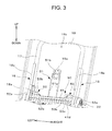
- Fig. 3 is a view illustrating a fixing mechanism according to this embodiment.
- Fig. 4 is a view illustrating an engagement portion and an anchor member according to this embodiment.
- Fig. 5 is a view illustrating the positional relation between a fixing mechanism and a seat back frame.
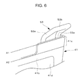
- Fig. 6 is an enlarged view of the periphery of a second anchor member according to this embodiment.
- Figs. 7 and 8 are views illustrating the anchor member that is attached to an anchor attachment member according to this embodiment.
- the front to back direction of the vehicle indicates the direction matching the traveling direction when the vehicle travels normally.
- the width direction of the vehicle indicates the right and left direction when the vehicle (the vehicle seat) is seen from the front side thereof.
- the up and down direction indicates the up and down direction when the vehicle is located on a flat surface.
- a seat 1 the entire configuration of the vehicle seat (hereinafter, referred to as a seat 1) according to this embodiment will be described.
- the seat 1 is a foldable seat, becomes a posture in which an occupant may sit on the seat in a use state, and becomes a folded posture in a non-use state.
- the seat 1 includes a seat cushion 4 and a seat back 6 as illustrated in Fig. 1 .
- the seat cushion 4 swings backward and downward in synchronization with this movement. Then, when the seat cushion 4 reaches the lower end and the rear end of the swing range, the seat back 6 is folded on the seat cushion 4.
- Such a state is a state (a non-use state) where the seat 1 is stowed.
- Such a state is a state (a use state) where an occupant may sit on the seat 1.
- the seat 1 includes a pair of right and left support brackets 2 and 2, and is fixed to a vehicle body through the support brackets 2 and 2. That is, the pair of right and left support brackets 2 and 2 is a portion which is formed so as to fix the seat 1 to the vehicle body.
- the support brackets are formed by performing a pressing work on a metal sheet.
- the support brackets 2 and 2 are fixed to the vehicle body while being located at both sides of the seat cushion 4.
- each of the support brackets 2 and 2 are formed by connecting and matching a plurality of segments.
- the support bracket includes a front end 11, a rear end 12, and an intermediate portion 13 which connects the front end 11 and the rear end 12 to each other.
- each of the support brackets 2 and 2 may be divided into three segments of the front end 11, the rear end 12, and the intermediate portion 13.
- the respective segments (that is, the front end 11, the rear end 12, and the intermediate portion 13) of the support brackets 2 and 2 are provided so as to be substantially perpendicular to the vehicle body floor. Furthermore, in this embodiment, a flared portion 2a which is projected outward is formed in the substantially entire circumference of the support brackets 2 and 2, and the rigidity of the support brackets 2 and 2 is ensured by forming such flared portions 2a.
- each of the support brackets 2 and 2 is attached to the lower end of the seat back 6 (precisely, a frame (a seat back frame) 16 of the seat back 6). More specifically, the seat back 6 rotates between the standing position (the position where the seat 1 is in a sittable state) and the laid position (the position where the seat 1 is in a stowable state) in a reciprocating manner as described above, and an extension shaft 22 which extends from the outer surface of the seat back frame and serving as a rotation shaft is fitted to a fitting hole formed in the rear end 12.
- each of the support brackets 2 and 2 are portions which support the seat cushion 4 through rotation arms 21 and 21 to be described later. Further, a substantially horizontal base wall 2b is adjacent to the lower end of the front end 11, and when such a base wall 2b is connected to the vehicle body floor by a bolt, the support brackets 2 and 2 is fixed to the vehicle body. As a result, the seat 1 is fixed to the vehicle body floor.
- the height (the length in the up and down direction) of the front end 11 is slightly larger than the height of the intermediate portion 13 or the rear end 12 located behind the front end 11. Accordingly, it is possible to ensure the rigidity of the front end 11 which receives a load in the support brackets 2 and 2 when the seat 1 is folded.
- connection pipe 3 which connects the front ends 11 of the support brackets 2 and 2 to each other is provided so as to suppress the support brackets 2 and 2 from falling inward (that is, toward the support brackets 2 and 2 which make a pair).
- the seat cushion 4 includes a seat cushion frame 14 which is disposed at a position interposed between the support brackets 2 and 2 in the width direction of the vehicle and serves as a frame.
- the seat cushion frame 14 includes a seat cushion frame base 31, front brackets 32 and 32, and a rear bracket 33.
- the seat cushion frame base 31 is formed as a pipe which is bent in a substantially U-shape, the left end thereof is provided with a left end frame 34, and the right end thereof is provided with a right end frame 35.
- the front brackets 32 and 32 are respectively welded to the front portions of the outer surfaces of the left end frame 34 and the right end frame 35.
- Each of the front brackets 32 and 32 includes a bulge portion 32a which bulges upward, and one-side longitudinal ends of the rotation arms 21 and 21 to be described later are fixed to the bulge portions 32a.
- the rear bracket 33 is disposed between the rear end of the left end frame 34 and the rear end of the right end frame 35 in the width direction of the seat 1.
- a seat cushion pan 36 is provided in the front end of the seat cushion frame 14 from the left front bracket 32 to the right front bracket 32, S-shaped springs (not illustrated) are provided between the rear end of the seat cushion pan 36 and the rear bracket 33, and a cushion material of the seat cushion 4 is placed on the S-shaped springs.
- the front end of the seat cushion pan 36 is hooked to the front end of the seat cushion frame base 31.
- the front end of the seat cushion pan is curved in a circular-arc shape so as to be hooked to the front end of the seat cushion frame base 31.
- the front end of the seat cushion pan 36 is not hooked to a position where a pipe forming the seat cushion frame base 31 is bent, that is, a position corresponding to the front corner of the seat cushion 4. This is because the occupant may feel uncomfortable when the occupant sits on the seat 1 in the case where the seat cushion pan 36 is hooked to the position corresponding to the front corner of the seat cushion 4. With the above-described configuration, the uncomfortable feeling may be suppressed.
- an attachment wire 37 to which a trim code attached to a terminal end of a trim cover covering the cushion material is hooked, is provided at the inside of the seat cushion frame base 31 (specifically, a position between the left end frame 34 and the right end frame 35 of the seat cushion frame base 31).
- the rotation arms 21 and 21 which are rotatable about the rotation shaft along the width direction of the vehicle, are provided as a pair of right and left rotation arms in the periphery of the seat cushion frame 14.
- the seat cushion frame 14 (specifically, the bulge portions 32a of the front brackets 32 and 32) is fixed to one-side longitudinal ends of each of the rotation arms 21 and 21.
- the seat cushion frame 14 swings in synchronization with the rotation of the rotation arms 21 and 21. That is, when the rotation arms 21 and 21 rotate, the seat cushion 4 swings in accordance with the rotation.
- rotation arms 21 and 21 The configurations of the rotation arms 21 and 21 will be described. As described above, one-side longitudinal ends of the rotation arms 21 and 21 are fixed to the bulge portions 32a of the front brackets 32 and 32 by bolts. The other-side longitudinal ends of the rotation arms 21 and 21 are rotatbly supported by the front ends 11 of the support brackets 2 and 2 through fixed pivots 20 and 20 as the rotation shafts. Thus, each of the rotation arms 21 and 21 are rotatable in the front to back direction and the up and down direction, and hence the seat cushion 4 swings in the same direction in accordance with the rotation.
- the seat cushion 4 When the seat cushion 4 reaches the front end and the upper end of the swing range, the seat cushion is located slightly above the vehicle body floor, and hence the occupant may sit on the seat cushion at such a position. That is, the position of the front end and the upper end of the swing range of the seat cushion 4 corresponds to the sitting position of the seat cushion 4. Furthermore, in the state where the seat cushion 4 is located at the sitting position, the rotation arms 21 and 21 are slightly inclined backward with respect to the perpendicular direction, and hence the seat cushion 4 takes a posture in which the front end of the seat cushion is raised in relation to the rear end thereof.
- the seat cushion 4 when the seat cushion 4 reaches the rear end and the lower end of the swing range, the seat cushion is stowed so as to approach the vehicle body floor. That is, the positions of the rear end and the lower end of the swing range of the seat cushion 4 correspond to the stowing position of the seat cushion 4. Furthermore, the stowing position is located below the sitting position. In the state where the seat cushion 4 is located at the stowing position, the rotation arms 21 and 21 and the seat cushion frame 14 are substantially horizontal.
- the seat cushion 4 moves between the sitting position and the stowing position in a reciprocating manner in accordance with the rotation of the rotation arms 21 and 21.
- the up and down direction of the seat back 6 indicates the up and down direction when the seat back 6 is in the standing state (that is, the seat 1 is in the use state).
- the front to back direction of the seat back 6 indicates the front to back direction when the seat back 6 is in the standing state.
- the seat back 6 includes a seat back frame 16 which is connected to the rear end of the seat cushion 4 and serves as a frame.
- the seat back frame 16 includes a seat back frame base 17, a pair of right and left side frames 18 and 18, and a back pan frame 19.
- the seat back frame base 17 is formed as a pipe which is bent in a substantially downward U-shape.
- the side frames 18 and 18 are respectively welded to the left end and the right end of the seat back frame base 17.
- the shapes of the side frames 18 and 18 will be described.
- the above-described extension shafts 22 are uprightly formed on the lower portions of the outer surfaces of the side frames 18 and 18, and the extension shafts 22 are fitted to the fitting holes formed in the rear ends 12 of the support brackets 2 and 2. Accordingly, the seat back 6 may swing about the extension shaft 22 in the front to back direction and the up and down direction.
- each of the side frames 18 and 18 includes a flared portion 18a which is formed by bending the front end and the rear end thereof so that the flared portion is projected inward (toward the side frames 18 which make a pair). Since such flared portions 18a are formed, the rigidity of the side frames 18 and 18 is ensured. Further, the front lower ends of the side frames 18 and 18 are provided with bulge portions 18b, and the bulge portions 18b engage with the outer surfaces of the corresponding frames of the left end frame 34 and the right end frame 35.
- connection bracket 41 which connects the lower ends of the side frames 18 and 18 to each other is provided between the side frames 18 and 18.
- the connection bracket 41 is a plate-shaped member that is elongated in the width direction of the seat 1, and both longitudinal ends thereof are fixed to the rear ends of the lower ends of the side frames 18 and 18 (more specifically, the rear-end-side flared portions 18a).
- anchor members 51, 52, and 53 are attached to the rear surface of the connection bracket 41 (the surface facing the back pan frame 19), and the anchor members 51, 52, and 53 engage with tether straps 71, 72, and 73 extending from a child seat when the child seat is attached to the seat 1 (for example, see Fig. 4 ).
- the back pan frame 19 is a pan frame which is located at the rear portion of the seat back frame 16, and is formed as a substantially rectangular metal panel in this embodiment. Then, the back pan frame is welded to the rear end of the seat back frame base 17 and the rear ends of the side frames 18 and 18. The width of the back pan frame 19 (the length in the right and left direction) is larger than the width of the seat cushion frame 14 by one size. Then, in the state where the seat 1 is folded, the entire seat cushion 4 is slid below the back pan frame 19.
- a rectangular hole 19a is formed at the substantial center position of the width direction of the back pan frame 19 (the lateral direction of the back pan frame 19) and the substantial center position of the height direction (the longitudinal direction of the back pan frame 19). Further, a circular hole 19b is formed at a position slightly above the formation position of the rectangular hole 19a (see Fig. 2A ).
- the seat 1 includes the above-described anchor members 51, 52, and 53 in order to fix the child seat. That is, when the child seat is placed on the seat 1 (more specifically, the seat cushion 4), the child seat may be fixed to the seat 1 by the anchor members 51, 52, and 53.
- the child seat fixing mechanism 50 including the anchor members 51, 52, and 53 will be described.
- the fixing mechanism 50 is provided in the seat so as to fix the child seat placed on the seat cushion 4, and includes the anchor members 51, 52, and 53 and an anchor attachment member for attaching the anchor members 51, 52, and 53 as illustrated in Figs. 3 to 5 .
- the anchor attachment member is formed by the connection bracket 41 which connects the lower ends of the side frames 18 and 18 to each other.
- the anchor members 51, 52, and 53 engage with the tether straps 71, 72, and 73 which extend from the child seat.
- the tether straps 71, 72, and 73 correspond to the engagement portions of the present invention, and are generally disposed at different positions of the child seat.
- the tether straps 71, 72, and 73 are located at different positions in a direction corresponding to the width direction of the seat 1. In this way, since the arrangement positions of each of the tether straps 71, 72, and 73 are different, the arrangement positions of the anchor members 51, 52, and 53 of the seat 1 are also different in the width direction of the seat 1.
- one anchor member 51 of the anchor members 51, 52, and 53 is the anchor member (hereinafter, referred to as the center anchor member 51) which is fixed to the connection bracket 41 at the center portion in the width direction of the seat 1, and corresponds to the first anchor member of the present invention.
- the lower end of the center anchor member 51 is fixed to the rear surface of the connection bracket 41.
- the center anchor member is disposed at a position interposed between the connection bracket 41 and the back pan frame 19 in the front to back direction of the seat 1 (that is, a position directly before the back pan frame 19).
- the corresponding tether strap (specifically, the first tether strap 71 to be described later) of the tether straps 71, 72, and 73 provided in the child seat engages with a portion located above the connection bracket 41 in the center anchor member 51.
- the corresponding tether strap indicates the tether strap which is located at the closest position in the state where the child seat is placed on the seat 1.
- a portion located above the connection bracket 41 in the center anchor member 51 has a substantially downward U-shape as illustrated in Fig. 3 , and includes a pair of upward extension portions 51a and 51a which extends upward in the height direction of the back pan frame 19 and a horizontal portion 51b which connects the tips (the upper ends) of the upward extension portions 51a and 51a to each other.
- Each of the pair of upward extension portions 51a and 51a extends so that the tip (the upper end) thereof reaches the vicinity of the center position of the back pan frame 19 in the height direction, and the horizontal portion 51b is exposed to the rear side of the back pan frame 19 through the rectangular hole 19a formed in the back pan frame 19.
- the above-described rectangular hole 19a corresponds to an exposure hole which exposes the center anchor member 51.
- the above-described circular hole 19b corresponds to an upper hole which is located above the rectangular hole 19a.
- the tether strap 71 (hereinafter, referred to as the first tether strap 71) corresponding to the first engagement portion in the tether straps 71, 72, and 73 provided in the child seat engages with the center anchor member 51 formed as described above.
- the first tether strap 71 penetrates the upper end of the seat back 6 from the front side of the seat back 6, passes through the circular hole 19b formed in the back pan frame 19 from the front side of the back pan frame 19 to the rear side thereof as illustrated in Fig. 4 , and extends so that an engagement hook 71a formed in the tip thereof is disposed in the rectangular hole 19a.
- the first tether strap 71 engages with the horizontal portion 51b of the center anchor member 51 from the rear surface side (the back surface side) of the back pan frame 19 through the rectangular hole 19a. That is, the horizontal portion 51b is an engagement target which is provided in the center anchor member 51 so as to engage with the first tether strap 71, and the center anchor member 51 engages with the engagement hook 71a of the first tether strap 71 disposed in the rectangular hole 19a by exposing the horizontal portion 51b through the rectangular hole 19a.
- the lower end of the center anchor member 51 is fixed to the connection bracket 41, and in this embodiment, the lower end is bent in an L-shape and extends toward the end of the connection bracket 41 in the longitudinal direction. That is, the lower end of the center anchor member 51 is provided with a joint target 51c which is joined to the connection bracket 41 (for example, see Fig. 7 ), the center anchor member is attached to the connection bracket 41 in a manner such that the joint target 51c is joined to the connection bracket 41. Then, in this embodiment, the joint target 51c of the center anchor member 51 extends in the longitudinal direction of the connection bracket 41.
- the other two anchor members 52 and 53 (that is, the anchor members other than the center anchor member 51) of the anchor members 51, 52, and 53 are fixed to the connection bracket 41 at positions interposing the center anchor member 51 in the width direction of the seat 1. That is, the two anchor members 52 and 53 correspond to the second anchor member of the present invention, and are disposed at positions different from the center anchor member 51 in the width direction of the seat 1. Specifically, the two anchor members 52 and 53 are disposed at positions adjacent to the inner ends of the side frames 18 and 18 (more specifically, the rear-end-side flared portions 18a).
- the anchor member 52 located at the left position is referred to as the left anchor member 52 and the anchor member 53 located at the right position is referred to as the right anchor member 53 among the two anchor members 52 and 53 when the seat 1 is seen from the front side.
- Both lower ends of the left anchor member 52 and the right anchor member 53 are fixed to the rear surface of the connection bracket 41, and are disposed at positions interposed between the connection bracket 41 and the back pan frame 19 (that is, positions directly before the back pan frame 19) in the front to back direction of the seat 1. That is, in this embodiment, all anchor members 51, 52, and 53 are provided at the same position in the front to back direction of the seat 1. Accordingly, the seat 1 having a compact size in the same direction is realized.
- the corresponding tether straps of the tether straps 71, 72, and 73 provided in the child seat engage with the portions located above the connection bracket 41 in the left anchor member 52 and the right anchor member 53.
- the left anchor member 52 engages with the second tether strap 72 located closest to the left anchor member 52
- the right anchor member 53 engages with the third tether strap 73 located closest to the right anchor member 53 while the child seat is placed on the seat 1.
- the left anchor member 52 will be described.
- the left anchor member 52 is formed in a substantially rectangular shape, and a portion located above the connection bracket 41 is formed in a substantially downward U-shape as illustrated in Fig. 3 .
- the left anchor member includes a pair of upward extension portions 52a and 52a which extends upward and a horizontal portion 52b which connects the tips (the upper ends) of the upward extension portions 52a and 52a to each other.
- the pair of upward extension portions 52a and 52a extends so that the tips (the upper ends) are located in the vicinity of the boundary between the seat cushion 4 and the seat back 6. Further, each of the pair of upward extension portions 52a and 52a is bent in a substantial V-shape at the halfway position thereof so that the tip thereof is located at the more front side as illustrated in Fig. 4 . That is, the left anchor member 52 is bent (bent forward) so that the upper portion of the left anchor member is located at the front side in relation to the lower portion thereof.
- the left anchor member 52 which is formed as described above engages with the second tether strap 72.
- the second tether strap 72 corresponds to the second engagement portion, and extends from a portion different from the first tether strap 71 in the child seat (specifically, different positions in the width direction of the child seat). Further, the second tether strap 72 is located at the front side of the left anchor member 52 and extends toward the upper end located at the more front side in the left anchor member 52 while the child seat is placed on the seat 1 as illustrated in Fig. 4 .
- the second tether strap 72 approaches the left anchor member 52 from the front side thereof, and the engagement hook 72a provided at the tip thereof engages with the horizontal portion 52b of the left anchor member 52. That is, the horizontal portion 52b is an engagement target which is provided in the left anchor member 52 so as to engage with the second tether strap 72, and the left anchor member 52 engages with the engagement hook 72a of the second tether strap 72 extending toward the horizontal portion 51b from the front side thereof.
- the left anchor member 52 is formed in an annular shape, and a portion facing the horizontal portion 52b in the lower end thereof corresponds to a joint target 52c joined to the connection bracket 41 (for example, see Fig. 8 ).
- the left anchor member 52 is attached to the connection bracket 41 in a manner such that the joint target 52c is joined to the connection bracket 41. That is, in this embodiment, the horizontal portion 52b as the engagement target is provided at a position equal to the joint target 52c in the up and down direction of the left anchor member 52. Then, the horizontal portion 52b and the joint target 52c of the left anchor member 52 extend in the longitudinal direction of the connection bracket 41.
- the right anchor member 53 is bilaterally symmetrical to the left anchor member 52, and has substantially the same structure as the left anchor member 52. That is, even the right anchor member 53 includes a pair of upward extension portions 53a and 53a which extends upward and a horizontal portion 53b which connects the tips (the upper ends) of the upward extension portions 51a and 51a to each other as in the left anchor member 52. Further, the right anchor member 53 is also bent (bent forward) so that the upper portion of the right anchor member is located at the front side in relation to the lower portion thereof (see Fig. 4 ).
- the right anchor member 53 engages with the third tether strap 73.
- the third tether strap 73 corresponds to the second engagement portion and extends from a portion different from the first tether strap 71 in the child seat (a different portion in the width direction of the child seat and a portion opposite to the second tether strap 72 when seen from the first tether strap 71). Then, the third tether strap 73 approaches the right anchor member 53 from the front side thereof, and the engagement hook 73a provided at the tip thereof engages with the horizontal portion 53b as the engagement target while the child seat is placed on the seat 1.
- the right anchor member 53 is also formed in an annular shape, the horizontal portion 53b as the engagement target is provided at the upper end thereof, and a joint target 53c joined to the connection bracket 41 is provided at the lower end facing the horizontal portion 53b (see Fig. 8 ). Then, even in the right anchor member 53, the horizontal portion 53b is formed at a position equal to the joint target 53c in the up and down direction. Further, the horizontal portion 53b and the joint target 53c of the right anchor member 53 extend in the longitudinal direction of the connection bracket 41.
- connection bracket 41 as the anchor attachment member is fixed to the rear ends of the lower ends of the side frames 18 and 18 in the seat back frame 16 while three anchor members 51, 52, and 53 are attached to the rear surface thereof. That is, all three anchor members 51, 52, and 53 (in other words, both the first anchor member and the second anchor member) are attached to the connection bracket 41, and the connection bracket 41 in such a state is supported by the seat back frame 16. That is, the seat back frame 16 according to this embodiment is used to support the fixing mechanism 50 by fixing the longitudinal ends of the connection bracket 41 to the rear ends of the lower ends of the side frames 18 and 18.
- each flared portion 18a faces a longitudinal end 41a of the connection bracket 41 (see Fig. 5 ). That is, each of the side frames 18 and 18 corresponds to the bent portion of the present invention, and the flared portion 18a which is formed by bending the rear end of each of the side frames 18 and 18 corresponds to the facing region of the present invention.
- connection bracket 41 when the longitudinal end 41a of the connection bracket 41 is attached to the flared portion 18a as the facing region, the seat back frame 16 supports the fixing mechanism 50.
- the anchor members 51, 52, and 53 are attached to a plurality of different positions of the connection bracket 41 as the common anchor attachment member, and the connection bracket 41 is attached to the highly rigid rear ends of the side frames 18 and 18 (more specifically, the rear flared portions 18a) in the seat back frame 16. That is, in this embodiment, the attachment portion of the connection bracket 41 in the seat back frame 16 becomes a portion of which the rigidity is further improved. As a result, the connection bracket 41 appropriately supports the plurality of anchor members 51, 52, and 53, and hence the anchor members 51, 52, and 53 are satisfactorily attached to the seat back frame 16.
- connection bracket 41 is bent a plurality of times at the halfway position in the longitudinal direction, and hence the longitudinal end 41a of the connection bracket 41 extends around the rear side of the flared portion 18a provided the rear end of each of the side frames 18 and 18. Meanwhile, a portion other than the longitudinal end 41a (that is, a portion interposed between the longitudinal ends 41a, and hereinafter, referred to as an anchor member attachment region 41b) in the connection bracket 41 is located at the front side of the longitudinal end 41a, and the anchor members 51, 52, and 53 are attached to the rear surface of the anchor member attachment region 41b.
- the center anchor member 51 is attached to the center portion of the anchor member attachment region 41b in the longitudinal direction of the connection bracket 41.
- the lower end of the center anchor member 51 is bent in an L-shape and extends toward the longitudinal end of the connection bracket 41 (see Fig. 7 ).
- a portion extending in the longitudinal direction of the connection bracket 41 forms the joint target 51c of the center anchor member 51, and the joint target 51c is joined to the connection bracket 41 so that the center anchor member 51 is attached to the connection bracket 41.
- the joint target 51c of the center anchor member 51 extends in the longitudinal direction of the connection bracket 41. In this way, when the joint target 51c follows the longitudinal direction of the connection bracket 41, the attachment space for the joint target 51c in the connection bracket 41 has a margin. For this reason, the joint target 51c may be easily lengthened, and hence the center anchor member 51 may be highly satisfactorily attached to the seat back frame 16.
- the left anchor member 52 is attached to one end (the left end) of the anchor member attachment region 41b in the longitudinal direction of the connection bracket 41.
- the right anchor member 53 is attached to the other end (the right end) of the anchor member attachment region 41b in the longitudinal direction of the connection bracket 41.
- a protrusion portion 41c is formed so as to protrude toward the upside of the center portion (for example, the attachment region of the center anchor member 51).
- the protrusion portion 41c is a portion which is provided in the connection bracket 41 so as to attach the above-described anchor member (specifically, the left anchor member 52 or the right anchor member 53) corresponding to the second anchor member.
- the above-described anchor members 52 and 53 are attached to the connection bracket 41 in a manner such that the joint targets 52c and 53c respectively provided at the lower portions of the left anchor member 52 and the right anchor member 53 are joined between the lower end (the position indicated by the sign A2 of Fig. 6 ) and the upper end (the position indicated by the sign A1 of Fig. 6 ) of the protrusion portion 41c. That is, the protrusion portions 41c protrude upward from the lower sides of the anchor members 52 and 53 while the anchor members 52 and 53 corresponding to the second anchor member are fixed to the connection bracket 41.
- the length of the protrusion portion 41c in the width direction of the seat 1 is longer than the lengths of the anchor members 52 and 53 corresponding to the second anchor member in the same direction. That is, the anchor members 52 and 53 corresponding to the second anchor member are fixed to the connection bracket 41 so that both left and right ends thereof are located between the left and right ends of the protrusion portion 41c.
- the upper end of the protrusion portion 41c is located between the lower end of each of the anchor members 52 and 53 and the bent position of each of the anchor members 52 and 53 in the up and down direction.
- the support rigidity for the left anchor member 52 and the support rigidity for the right anchor member 53 in the connection bracket 41 are improved in this embodiment, and hence the anchor members 52 and 53 may be more satisfactorily attached to the seat back frame 16.
- the protrusion portion 41c is formed so as to be lengthened in the longitudinal direction of the connection bracket 41.
- each of the joint targets 52c and 53c of the left anchor member 52 and the right anchor member 53 are joined to the rear surfaces of the protrusion portions 41c while the extension direction thereof follows the longitudinal direction of the connection bracket 41.
- the joint targets 52c and 53c follow the longitudinal direction of the connection bracket 41, there is a margin in the attachment space (specifically, the protrusion portion 41c) of the joint target 52c in the connection bracket 41. Accordingly, the above-described joint targets 52c and 53c may be easily lengthened, and hence the left anchor member 52 and the right anchor member 53 may be highly satisfactorily attached to the seat back frame 16.
- connection bracket 41 includes a raised portion 41d which is formed at the rear surface side by performing a pressing process (a pressing work) from the front surface side thereof (for example, see Fig. 2B , 3 , and 4 ).
- the raised portion 41d is located at the halfway position of the connection bracket 41 in the height direction, and is formed from the arrival position of the left protrusion portion 41c to the arrival position of the right protrusion portion 41c in the longitudinal direction of the connection bracket 41. Since the raised portion 41d is formed, the rigidity of the connection bracket 41 is improved. As a result, the connection bracket 41 more appropriately supports the plurality of anchor members 51, 52, and 53.
- the lower end position of the center anchor member 51 is defined by the above-described raised portion 41d. More specifically, the above-described raised portion 41d is raised from the rear surface of the connection bracket 41 (see Fig. 4 ), and is formed in the longitudinal direction of the connection bracket 41. When the lower end of the center anchor member 51 (specifically, the joint target 51c) comes into contact with such a raised portion 41d, the lower end position of the center anchor member 51 is regulated and positioned by the raised portion 41d.
- the raised portion 41d formed in the connection bracket 41 serves as a positioning portion with respect to the anchor member (specifically, the center anchor member 51), the lower end position of the anchor member may be positioned without preparing a separate member. Furthermore, in this embodiment, the lower end position of the center anchor member 51 is positioned by the raised portion 41d. However, the raised portion 41d may position the lower end position of at least any anchor member (in other words, at least one anchor member of the first anchor member and the second anchor member) of the above-described three anchor members 51, 52, and 53.
- the vehicle seat with three anchor members 51, 52, and 53 has been described, but the number of the anchor members may be freely set as long as at least two anchor members are provided.
- the anchor member 51 has been described as an example of the first anchor member that engages with the tether strap (that is, the first tether strap 71) which passes through the circular hole 19b formed in the back pan frame 19 from the front side of the frame to the rear side thereof and extends so that the tip thereof is disposed in the rectangular hole 19a.
- the anchor members 52 and 53 have been described as an example of the second anchor member that engages with the tether straps (that is, the second tether strap 72 and the third tether strap 73) extending from the front side thereof.
- the vehicle seat that is, the seat 1 according to the above-described embodiment, the first anchor member and the second anchor member above-described may be satisfactorily attached to the seat back frame 16.
- the above-described anchor member is merely an example, and may be an anchor member having the other structure.
- an anchor member that engages with a fixed arm instead of the tether strap may be also employed.
- connection bracket 41 to which the anchor members are attached is elongated in the width direction of the vehicle seat, and both longitudinal ends of the connection bracket 41 are attached to the rear ends of the lower ends of the side frames 18 and 18 in the seat back frame 16.
- the present invention is not limited thereto.
- only one of both longitudinal ends of the connection bracket 41 may be attached to the corresponding side frame 18 among the pair of side frames 18 and 18.
- each of the anchor members 51, 52, and 53 include the joint targets 51c, 52c, and 53c joined to the connection bracket 41, and the joint targets 51c, 52c, and 53c are joined to the connection bracket 41 so as to be attached to the connection bracket 41. Then, in the above-described embodiment, all joint targets 51c, 52c, and 53c of each of the anchor members 51, 52, and 53 follow the longitudinal direction of the connection bracket 41.
- the present invention is not limited thereto.
- the joint target of at least one anchor member of the anchor member (the center anchor member 51) corresponding to the first anchor member and the anchor member (the left anchor member 52 and the right anchor member 53) corresponding to the second anchor member may follow the longitudinal direction of the connection bracket 41.
- the anchor member (the left anchor member 52 or the right anchor member 53) corresponding to the second anchor member is formed in an annular shape, and the above-described joint targets 52c and 53c and the engagement targets (specifically, the horizontal portions 52b and 53b) engaging with the engagement portion of the child seat are arranged in series in the up and down direction.
- Such a configuration is not limited to the anchor member corresponding to the second anchor member, and may be also applied to the anchor member (the center anchor member 51) corresponding to the first anchor member. That is, the engagement target may be provided at a position equal to the joint target in the up and down direction in at least one anchor member of the anchor member corresponding to the first anchor member and the anchor member corresponding to the second anchor member.
Landscapes
- Engineering & Computer Science (AREA)
- Aviation & Aerospace Engineering (AREA)
- Transportation (AREA)
- Mechanical Engineering (AREA)
- Health & Medical Sciences (AREA)
- Child & Adolescent Psychology (AREA)
- General Health & Medical Sciences (AREA)
- Seats For Vehicles (AREA)
- Chair Legs, Seat Parts, And Backrests (AREA)
Description
- The present invention relates to a vehicle seat, and particularly, to a vehicle seat including a fixing mechanism which is placed on a child seat so as to fix the child seat and a seat back frame which supports the fixing mechanism.
- Among vehicle seats, there is known a vehicle seat including a mechanism (hereinafter, referred to as a fixing mechanism) that fixes a child seat placed on a seat cushion. The fixing mechanism includes an anchor member that engages with an engagement portion extending from the child seat. Further, in the vehicle seat including the fixing mechanism, the anchor member may be attached to a seat frame through an anchor attachment member such as a bracket (for example, see Patent Document 1). In the vehicle seat disclosed in
Patent Document 1, a striker engaging with a fixed arm extending from the child seat is provided as the anchor member, and the striker is attached to a seat cushion frame through a bracket. - Patent Document 1:
JP 2001-105941 A - Incidentally, it is considered that the anchor members are provided in the vehicle seat as many as the engagement portions as a plurality of engagement portions are provided in the child seat from the purpose of more rigidly fixing the child seat to the vehicle seat. In the case where the plurality of anchor members are provided in the vehicle seat, the anchor members are generally disposed at different positions. In such a configuration, it is difficult to keep the anchor members at predetermined arrangement positions when the rigidity of a portion for fixing the anchor attachment member in the frame is low in the case where the anchor members are attached to the seat frame through the anchor attachment member such as a bracket as described above. As a result, the engagement portions provided in the child seat do not appropriately engage with the anchor members, and hence there is a concern that the child seat is not satisfactorily fixed to the vehicle seat.
- Therefore, the present invention is made in view of the above-described circumstances, and an object thereof is to realize a vehicle seat capable of satisfactorily attaching anchor members to a seat back frame even if a plurality of anchor members are provided at different positions in a structure in which the anchor members engaging with engagement portions extending from a child seat are attached to a seat back frame through an anchor attachment member such as a bracket.
- According to a vehicle seat of the present invention, the above-described problem is solved by a vehicle seat that places a child seat thereon and includes a fixing mechanism fixing the child seat and a seat back frame supporting the fixing mechanism, wherein the fixing mechanism includes a first anchor member that engages with a first engagement portion extending from the child seat, a second anchor member that engages with a second engagement portion extending from a portion different from the first engagement portion of the child seat and is disposed at a position different from the first anchor member, and an anchor attachment member to which both the first anchor member and the second anchor member are attached, wherein the seat back frame comprises a bent portion formed by bending that includes a facing region facing the anchor attachment member, and supports the fixing mechanism by attaching the anchor attachment member to the facing region.
- In the vehicle seat with such a configuration, the plurality of anchor members are attached to different positions of the common anchor attachment member, and the anchor attachment member is attached to the bent portion (more specifically, the facing region in the bent portion) having high rigidity in the seat back frame. Then, the anchor attachment member appropriately supports the plurality of anchor members as a result of the improved rigidity of the attachment portion for the anchor attachment member in the seat back frame. That is, in the vehicle seat of the present invention, the anchor members may be satisfactorily attached to the seat back frame.
- Further, in the above-described vehicle seat, the seat back frame may include a pan frame that is located at a rear portion of the seat back frame, the pan frame may include an exposure hole that exposes the first anchor member and an upper hole that is located above the exposure hole, the fixing mechanism may be located at the front side of the pan frame, the first anchor member may engage with the first engagement portion that passes through the upper hole from the front side of the pan frame to the rear side thereof and extends so that the tip thereof is disposed in the exposure hole, and the second anchor member may engage with the second engagement portion that extends from the front side of the second anchor member toward the second anchor member.
- In the vehicle seat with the above-described configuration, the first anchor member and the second anchor member may be satisfactorily attached to the seat back frame.
- Further, in the above-described vehicle seat, the second anchor member may be bent so that an upper portion of the second anchor member is located at the front side of a lower portion of the second anchor member, the anchor attachment member may include a protrusion portion that protrudes upward from the lower side of the second anchor member so as to attach the second anchor member, the length of the protrusion portion in the width direction of the vehicle seat may be longer than the length of the second anchor member in the width direction, and an upper end of the protrusion portion may be located between a lower end of the second anchor member and a bent position of the second anchor member in the up and down direction.
- In the vehicle seat with the above-described configuration, since the support rigidity for the second anchor member in the anchor attachment member is improved, the second anchor member may be more satisfactorily attached to the seat back frame.
- Further, in the above-described vehicle seat, the anchor attachment member may be a plate-shaped member, both the first anchor member and the second anchor member may be attached to a rear surface of the plate-shaped member, the plate-shaped member may include a raised portion that is formed at the rear surface of the plate-shaped member by pressing the plate-shaped member from the front surface side thereof, and a lower end position of at least one anchor member of the first anchor member and the second anchor member may be positioned by the raised portion.
- In the vehicle seat with the above-described configuration, the lower end position of at least one anchor member may be positioned even when a separate member is not prepared. Further, the rigidity of the anchor attachment member may be improved.
- Further, in the above-described vehicle seat, the anchor attachment member may be an elongated plate-shaped member, both the first anchor member and the second anchor member may include joint targets that are joined to the plate-shaped member, the joint targets may be joined to the plate-shaped member so as to be attached to the plate-shaped member, and the joint target of at least one anchor member of the first anchor member and the second anchor member may follow the longitudinal direction of the plate-shaped member.
- In the vehicle seat with the above-described configuration, since the joint target may be easily lengthened, at least one anchor member (the anchor member of which the joint target follows the longitudinal direction of the plate-shaped member) may be more satisfactorily attached to the seat back frame.
- Further, in the above-described vehicle seat, the at least one anchor member may include an engagement target that engages with the engagement portion corresponding to the at least one anchor member in the first engagement portion and the second engagement portion, and the engagement target may be provided at a position equal to the joint target in the up and down direction in the at least one anchor member.
- In the vehicle seat with the above-described configuration, since the engagement target may be easily lengthened, it is possible to stabilize the engagement state between at least one anchor member and the engagement portion corresponding to the anchor member.
- According to the present invention, it is possible to satisfactorily attach the plurality of anchor members to the seat back frame.
- According to the present invention, it is possible to satisfactorily attach the first anchor member and the second anchor member formed so as to engage with the corresponding engagement portions to the seat back frame.
- According to the present invention, it is possible to more satisfactorily attach the second anchor member to the seat back frame.
- According to the present invention, it is possible to position the lower end position of at least one anchor member even when a separate member is not prepared. Further, it is possible to improve the rigidity of the anchor attachment member.
- According to the present invention, since the joint target of at least one anchor member may be easily lengthened, it is possible to more satisfactorily attach the anchor member to the seat back frame.
- According to the present invention, since the engagement target of at least one anchor member may be easily lengthened, it is possible to stabilize the engagement state between at least one anchor member and the engagement portion corresponding to the anchor member.
-
-
Fig. 1 is a perspective view illustrating a vehicle seat according to this embodiment; -
Fig. 2A is a perspective view illustrating the inner structure of the vehicle seat according to this embodiment; -
Fig. 2B is a view in which the inner structure of the vehicle seat according to this embodiment is seen from the front side and the top side thereof; -
Fig. 3 is a view illustrating a fixing mechanism according to this embodiment; -
Fig. 4 is a view illustrating an engagement portion and an anchor member according to this embodiment; -
Fig. 5 is a view illustrating the positional relation between a fixing mechanism and a seat back frame; -
Fig. 6 is an enlarged view of the periphery of a second anchor member according to this embodiment; -
Fig. 7 is a (first) view illustrating the anchor member that is attached to an anchor attachment member according to this embodiment; and -
Fig. 8 is a (second) view illustrating the anchor member that is attached to the anchor attachment member according to this embodiment. - Hereinafter, an embodiment (hereinafter, referred to as this embodiment) of the present invention will be described with reference to
Figs. 1 to 8 . -
Fig. 1 is a perspective view of a vehicle seat according to this embodiment.Figs. 2A and2B are views illustrating the inner structure of the vehicle seat according to this embodiment, whereFig. 2A is a perspective view of the inner structure andFig. 2B is a view in which the inner structure is seen from the front side and the top side thereof.Fig. 3 is a view illustrating a fixing mechanism according to this embodiment.Fig. 4 is a view illustrating an engagement portion and an anchor member according to this embodiment.Fig. 5 is a view illustrating the positional relation between a fixing mechanism and a seat back frame.Fig. 6 is an enlarged view of the periphery of a second anchor member according to this embodiment.Figs. 7 and8 are views illustrating the anchor member that is attached to an anchor attachment member according to this embodiment. - In the description below, the front to back direction of the vehicle (the vehicle seat) indicates the direction matching the traveling direction when the vehicle travels normally. Further, the width direction of the vehicle (the vehicle seat) indicates the right and left direction when the vehicle (the vehicle seat) is seen from the front side thereof. Further, in the description below, the up and down direction indicates the up and down direction when the vehicle is located on a flat surface.
- First, the entire configuration of the vehicle seat (hereinafter, referred to as a seat 1) according to this embodiment will be described.
- The
seat 1 is a foldable seat, becomes a posture in which an occupant may sit on the seat in a use state, and becomes a folded posture in a non-use state. - Specifically, the
seat 1 includes aseat cushion 4 and a seat back 6 as illustrated inFig. 1 . When the seat back 6 is laid forward from the standing state, theseat cushion 4 swings backward and downward in synchronization with this movement. Then, when theseat cushion 4 reaches the lower end and the rear end of the swing range, the seat back 6 is folded on theseat cushion 4. Such a state is a state (a non-use state) where theseat 1 is stowed. - Meanwhile, when the seat back 6 is returned from the laid state to the standing state, the
seat cushion 4 swings forward and upward in synchronization with this movement. Then, when theseat cushion 4 reaches the upper end and the front end of the swing range, theseat cushion 4 is located slightly above a vehicle body floor, and hence the seat back 6 stands so as to be substantially perpendicular to theseat cushion 4. Such a state is a state (a use state) where an occupant may sit on theseat 1. - Further, the
seat 1 includes a pair of right and leftsupport brackets support brackets support brackets seat 1 to the vehicle body. In this embodiment, the support brackets are formed by performing a pressing work on a metal sheet. Furthermore, in this embodiment, thesupport brackets seat cushion 4. - Here, the structures of each of the
support brackets Figs. 2A and2B , and each of thesupport brackets front end 11, arear end 12, and anintermediate portion 13 which connects thefront end 11 and therear end 12 to each other. In other words, each of thesupport brackets front end 11, therear end 12, and theintermediate portion 13. - The respective segments (that is, the
front end 11, therear end 12, and the intermediate portion 13) of thesupport brackets portion 2a which is projected outward is formed in the substantially entire circumference of thesupport brackets support brackets portions 2a. - The
rear end 12 of each of thesupport brackets seat 1 is in a sittable state) and the laid position (the position where theseat 1 is in a stowable state) in a reciprocating manner as described above, and anextension shaft 22 which extends from the outer surface of the seat back frame and serving as a rotation shaft is fitted to a fitting hole formed in therear end 12. - The front ends 11 of each of the
support brackets seat cushion 4 throughrotation arms horizontal base wall 2b is adjacent to the lower end of thefront end 11, and when such abase wall 2b is connected to the vehicle body floor by a bolt, thesupport brackets seat 1 is fixed to the vehicle body floor. - Furthermore, in this embodiment, the height (the length in the up and down direction) of the
front end 11 is slightly larger than the height of theintermediate portion 13 or therear end 12 located behind thefront end 11. Accordingly, it is possible to ensure the rigidity of thefront end 11 which receives a load in thesupport brackets seat 1 is folded. - Further, in this embodiment, a
connection pipe 3 which connects the front ends 11 of thesupport brackets support brackets support brackets - Next, the
seat cushion 4 and the peripheral components will be described with reference toFigs. 2A and2B . Theseat cushion 4 includes aseat cushion frame 14 which is disposed at a position interposed between thesupport brackets seat cushion frame 14 includes a seatcushion frame base 31,front brackets rear bracket 33. The seatcushion frame base 31 is formed as a pipe which is bent in a substantially U-shape, the left end thereof is provided with aleft end frame 34, and the right end thereof is provided with aright end frame 35. - The
front brackets left end frame 34 and theright end frame 35. Each of thefront brackets bulge portion 32a which bulges upward, and one-side longitudinal ends of therotation arms bulge portions 32a. - The
rear bracket 33 is disposed between the rear end of theleft end frame 34 and the rear end of theright end frame 35 in the width direction of theseat 1. - Further, a
seat cushion pan 36 is provided in the front end of theseat cushion frame 14 from theleft front bracket 32 to theright front bracket 32, S-shaped springs (not illustrated) are provided between the rear end of theseat cushion pan 36 and therear bracket 33, and a cushion material of theseat cushion 4 is placed on the S-shaped springs. - Furthermore, the front end of the
seat cushion pan 36 is hooked to the front end of the seatcushion frame base 31. Specifically, the front end of the seat cushion pan is curved in a circular-arc shape so as to be hooked to the front end of the seatcushion frame base 31. Meanwhile, the front end of theseat cushion pan 36 is not hooked to a position where a pipe forming the seatcushion frame base 31 is bent, that is, a position corresponding to the front corner of theseat cushion 4. This is because the occupant may feel uncomfortable when the occupant sits on theseat 1 in the case where theseat cushion pan 36 is hooked to the position corresponding to the front corner of theseat cushion 4. With the above-described configuration, the uncomfortable feeling may be suppressed. - Further, an
attachment wire 37, to which a trim code attached to a terminal end of a trim cover covering the cushion material is hooked, is provided at the inside of the seat cushion frame base 31 (specifically, a position between theleft end frame 34 and theright end frame 35 of the seat cushion frame base 31). - Meanwhile, the
rotation arms seat cushion frame 14. As described above, the seat cushion frame 14 (specifically, thebulge portions 32a of thefront brackets 32 and 32) is fixed to one-side longitudinal ends of each of therotation arms seat cushion frame 14 swings in synchronization with the rotation of therotation arms rotation arms seat cushion 4 swings in accordance with the rotation. - The configurations of the
rotation arms rotation arms bulge portions 32a of thefront brackets rotation arms support brackets pivots rotation arms seat cushion 4 swings in the same direction in accordance with the rotation. - When the
seat cushion 4 reaches the front end and the upper end of the swing range, the seat cushion is located slightly above the vehicle body floor, and hence the occupant may sit on the seat cushion at such a position. That is, the position of the front end and the upper end of the swing range of theseat cushion 4 corresponds to the sitting position of theseat cushion 4. Furthermore, in the state where theseat cushion 4 is located at the sitting position, therotation arms seat cushion 4 takes a posture in which the front end of the seat cushion is raised in relation to the rear end thereof. - On the other hand, when the
seat cushion 4 reaches the rear end and the lower end of the swing range, the seat cushion is stowed so as to approach the vehicle body floor. That is, the positions of the rear end and the lower end of the swing range of theseat cushion 4 correspond to the stowing position of theseat cushion 4. Furthermore, the stowing position is located below the sitting position. In the state where theseat cushion 4 is located at the stowing position, therotation arms seat cushion frame 14 are substantially horizontal. - As described above, the
seat cushion 4 according to this embodiment moves between the sitting position and the stowing position in a reciprocating manner in accordance with the rotation of therotation arms - Next, the structure of the seat back 6 will be described with reference to
Figs. 2A and2B . Furthermore, in the description below, the up and down direction of the seat back 6 indicates the up and down direction when the seat back 6 is in the standing state (that is, theseat 1 is in the use state). Similarly, the front to back direction of the seat back 6 indicates the front to back direction when the seat back 6 is in the standing state. - The seat back 6 includes a seat back
frame 16 which is connected to the rear end of theseat cushion 4 and serves as a frame. The seat backframe 16 includes a seat backframe base 17, a pair of right and left side frames 18 and 18, and aback pan frame 19. The seat backframe base 17 is formed as a pipe which is bent in a substantially downward U-shape. The side frames 18 and 18 are respectively welded to the left end and the right end of the seat backframe base 17. - The shapes of the side frames 18 and 18 will be described. The above-described
extension shafts 22 are uprightly formed on the lower portions of the outer surfaces of the side frames 18 and 18, and theextension shafts 22 are fitted to the fitting holes formed in the rear ends 12 of thesupport brackets extension shaft 22 in the front to back direction and the up and down direction. - Further, each of the side frames 18 and 18 includes a flared
portion 18a which is formed by bending the front end and the rear end thereof so that the flared portion is projected inward (toward the side frames 18 which make a pair). Since such flaredportions 18a are formed, the rigidity of the side frames 18 and 18 is ensured. Further, the front lower ends of the side frames 18 and 18 are provided withbulge portions 18b, and thebulge portions 18b engage with the outer surfaces of the corresponding frames of theleft end frame 34 and theright end frame 35. - Furthermore, a
connection bracket 41 which connects the lower ends of the side frames 18 and 18 to each other is provided between the side frames 18 and 18. Theconnection bracket 41 is a plate-shaped member that is elongated in the width direction of theseat 1, and both longitudinal ends thereof are fixed to the rear ends of the lower ends of the side frames 18 and 18 (more specifically, the rear-end-side flaredportions 18a). Further,anchor members anchor members tether straps Fig. 4 ). - The
back pan frame 19 is a pan frame which is located at the rear portion of the seat backframe 16, and is formed as a substantially rectangular metal panel in this embodiment. Then, the back pan frame is welded to the rear end of the seat backframe base 17 and the rear ends of the side frames 18 and 18. The width of the back pan frame 19 (the length in the right and left direction) is larger than the width of theseat cushion frame 14 by one size. Then, in the state where theseat 1 is folded, theentire seat cushion 4 is slid below theback pan frame 19. - Further, a
rectangular hole 19a is formed at the substantial center position of the width direction of the back pan frame 19 (the lateral direction of the back pan frame 19) and the substantial center position of the height direction (the longitudinal direction of the back pan frame 19). Further, acircular hole 19b is formed at a position slightly above the formation position of therectangular hole 19a (seeFig. 2A ). - The
seat 1 includes the above-describedanchor members seat 1 by theanchor members - Hereinafter, the child
seat fixing mechanism 50 including theanchor members - The fixing
mechanism 50 is provided in the seat so as to fix the child seat placed on theseat cushion 4, and includes theanchor members anchor members Figs. 3 to 5 . Furthermore, in this embodiment, the anchor attachment member is formed by theconnection bracket 41 which connects the lower ends of the side frames 18 and 18 to each other. - The
anchor members seat 1, the tether straps 71, 72, and 73 are located at different positions in a direction corresponding to the width direction of theseat 1. In this way, since the arrangement positions of each of the tether straps 71, 72, and 73 are different, the arrangement positions of theanchor members seat 1 are also different in the width direction of theseat 1. - Specifically, one
anchor member 51 of theanchor members connection bracket 41 at the center portion in the width direction of theseat 1, and corresponds to the first anchor member of the present invention. The lower end of thecenter anchor member 51 is fixed to the rear surface of theconnection bracket 41. As illustrated inFig. 5 , the center anchor member is disposed at a position interposed between theconnection bracket 41 and theback pan frame 19 in the front to back direction of the seat 1 (that is, a position directly before the back pan frame 19). - Then, the corresponding tether strap (specifically, the
first tether strap 71 to be described later) of the tether straps 71, 72, and 73 provided in the child seat engages with a portion located above theconnection bracket 41 in thecenter anchor member 51. Here, the corresponding tether strap indicates the tether strap which is located at the closest position in the state where the child seat is placed on theseat 1. - More specifically, a portion located above the
connection bracket 41 in thecenter anchor member 51 has a substantially downward U-shape as illustrated inFig. 3 , and includes a pair ofupward extension portions back pan frame 19 and ahorizontal portion 51b which connects the tips (the upper ends) of theupward extension portions - Each of the pair of
upward extension portions back pan frame 19 in the height direction, and thehorizontal portion 51b is exposed to the rear side of theback pan frame 19 through therectangular hole 19a formed in theback pan frame 19. Here, the above-describedrectangular hole 19a corresponds to an exposure hole which exposes thecenter anchor member 51. Meanwhile, the above-describedcircular hole 19b corresponds to an upper hole which is located above therectangular hole 19a. - The tether strap 71 (hereinafter, referred to as the first tether strap 71) corresponding to the first engagement portion in the tether straps 71, 72, and 73 provided in the child seat engages with the
center anchor member 51 formed as described above. In the state where the child seat is placed on theseat 1, thefirst tether strap 71 penetrates the upper end of the seat back 6 from the front side of the seat back 6, passes through thecircular hole 19b formed in theback pan frame 19 from the front side of theback pan frame 19 to the rear side thereof as illustrated inFig. 4 , and extends so that anengagement hook 71a formed in the tip thereof is disposed in therectangular hole 19a. - Then, the
first tether strap 71 engages with thehorizontal portion 51b of thecenter anchor member 51 from the rear surface side (the back surface side) of theback pan frame 19 through therectangular hole 19a. That is, thehorizontal portion 51b is an engagement target which is provided in thecenter anchor member 51 so as to engage with thefirst tether strap 71, and thecenter anchor member 51 engages with theengagement hook 71a of thefirst tether strap 71 disposed in therectangular hole 19a by exposing thehorizontal portion 51b through therectangular hole 19a. - Furthermore, the lower end of the
center anchor member 51 is fixed to theconnection bracket 41, and in this embodiment, the lower end is bent in an L-shape and extends toward the end of theconnection bracket 41 in the longitudinal direction. That is, the lower end of thecenter anchor member 51 is provided with ajoint target 51c which is joined to the connection bracket 41 (for example, seeFig. 7 ), the center anchor member is attached to theconnection bracket 41 in a manner such that thejoint target 51c is joined to theconnection bracket 41. Then, in this embodiment, thejoint target 51c of thecenter anchor member 51 extends in the longitudinal direction of theconnection bracket 41. - The other two
anchor members 52 and 53 (that is, the anchor members other than the center anchor member 51) of theanchor members connection bracket 41 at positions interposing thecenter anchor member 51 in the width direction of theseat 1. That is, the twoanchor members center anchor member 51 in the width direction of theseat 1. Specifically, the twoanchor members portions 18a). Furthermore, in the description below, theanchor member 52 located at the left position is referred to as theleft anchor member 52 and theanchor member 53 located at the right position is referred to as theright anchor member 53 among the twoanchor members seat 1 is seen from the front side. - Both lower ends of the
left anchor member 52 and theright anchor member 53 are fixed to the rear surface of theconnection bracket 41, and are disposed at positions interposed between theconnection bracket 41 and the back pan frame 19 (that is, positions directly before the back pan frame 19) in the front to back direction of theseat 1. That is, in this embodiment, allanchor members seat 1. Accordingly, theseat 1 having a compact size in the same direction is realized. - Then, the corresponding tether straps of the tether straps 71, 72, and 73 provided in the child seat engage with the portions located above the
connection bracket 41 in theleft anchor member 52 and theright anchor member 53. Specifically, theleft anchor member 52 engages with thesecond tether strap 72 located closest to theleft anchor member 52 and theright anchor member 53 engages with thethird tether strap 73 located closest to theright anchor member 53 while the child seat is placed on theseat 1. - The
left anchor member 52 will be described. Theleft anchor member 52 is formed in a substantially rectangular shape, and a portion located above theconnection bracket 41 is formed in a substantially downward U-shape as illustrated inFig. 3 . Then, the left anchor member includes a pair ofupward extension portions horizontal portion 52b which connects the tips (the upper ends) of theupward extension portions - The pair of
upward extension portions seat cushion 4 and the seat back 6. Further, each of the pair ofupward extension portions Fig. 4 . That is, theleft anchor member 52 is bent (bent forward) so that the upper portion of the left anchor member is located at the front side in relation to the lower portion thereof. - The
left anchor member 52 which is formed as described above engages with thesecond tether strap 72. Thesecond tether strap 72 corresponds to the second engagement portion, and extends from a portion different from thefirst tether strap 71 in the child seat (specifically, different positions in the width direction of the child seat). Further, thesecond tether strap 72 is located at the front side of theleft anchor member 52 and extends toward the upper end located at the more front side in theleft anchor member 52 while the child seat is placed on theseat 1 as illustrated inFig. 4 . - Then, the
second tether strap 72 approaches theleft anchor member 52 from the front side thereof, and theengagement hook 72a provided at the tip thereof engages with thehorizontal portion 52b of theleft anchor member 52. That is, thehorizontal portion 52b is an engagement target which is provided in theleft anchor member 52 so as to engage with thesecond tether strap 72, and theleft anchor member 52 engages with theengagement hook 72a of thesecond tether strap 72 extending toward thehorizontal portion 51b from the front side thereof. - Furthermore, in this embodiment, the
left anchor member 52 is formed in an annular shape, and a portion facing thehorizontal portion 52b in the lower end thereof corresponds to ajoint target 52c joined to the connection bracket 41 (for example, seeFig. 8 ). Theleft anchor member 52 is attached to theconnection bracket 41 in a manner such that thejoint target 52c is joined to theconnection bracket 41. That is, in this embodiment, thehorizontal portion 52b as the engagement target is provided at a position equal to thejoint target 52c in the up and down direction of theleft anchor member 52. Then, thehorizontal portion 52b and thejoint target 52c of theleft anchor member 52 extend in the longitudinal direction of theconnection bracket 41. - The
right anchor member 53 is bilaterally symmetrical to theleft anchor member 52, and has substantially the same structure as theleft anchor member 52. That is, even theright anchor member 53 includes a pair ofupward extension portions horizontal portion 53b which connects the tips (the upper ends) of theupward extension portions left anchor member 52. Further, theright anchor member 53 is also bent (bent forward) so that the upper portion of the right anchor member is located at the front side in relation to the lower portion thereof (seeFig. 4 ). - As described above, the
right anchor member 53 engages with thethird tether strap 73. Thethird tether strap 73 corresponds to the second engagement portion and extends from a portion different from thefirst tether strap 71 in the child seat (a different portion in the width direction of the child seat and a portion opposite to thesecond tether strap 72 when seen from the first tether strap 71). Then, thethird tether strap 73 approaches theright anchor member 53 from the front side thereof, and theengagement hook 73a provided at the tip thereof engages with thehorizontal portion 53b as the engagement target while the child seat is placed on theseat 1. - Furthermore, the
right anchor member 53 is also formed in an annular shape, thehorizontal portion 53b as the engagement target is provided at the upper end thereof, and ajoint target 53c joined to theconnection bracket 41 is provided at the lower end facing thehorizontal portion 53b (seeFig. 8 ). Then, even in theright anchor member 53, thehorizontal portion 53b is formed at a position equal to thejoint target 53c in the up and down direction. Further, thehorizontal portion 53b and thejoint target 53c of theright anchor member 53 extend in the longitudinal direction of theconnection bracket 41. - The
connection bracket 41 as the anchor attachment member is fixed to the rear ends of the lower ends of the side frames 18 and 18 in the seat backframe 16 while threeanchor members anchor members connection bracket 41, and theconnection bracket 41 in such a state is supported by the seat backframe 16. That is, the seat backframe 16 according to this embodiment is used to support thefixing mechanism 50 by fixing the longitudinal ends of theconnection bracket 41 to the rear ends of the lower ends of the side frames 18 and 18. - Here, the rear ends of the side frames 18 and 18 are bent so as to ensure the rigidity thereof as described above, and hence the flared
portions 18a which are projected inward are formed by the bending work. Each flaredportion 18a faces alongitudinal end 41a of the connection bracket 41 (seeFig. 5 ). That is, each of the side frames 18 and 18 corresponds to the bent portion of the present invention, and the flaredportion 18a which is formed by bending the rear end of each of the side frames 18 and 18 corresponds to the facing region of the present invention. - Then, when the
longitudinal end 41a of theconnection bracket 41 is attached to the flaredportion 18a as the facing region, the seat backframe 16 supports thefixing mechanism 50. - As described above, in this embodiment, the
anchor members connection bracket 41 as the common anchor attachment member, and theconnection bracket 41 is attached to the highly rigid rear ends of the side frames 18 and 18 (more specifically, the rear flaredportions 18a) in the seat backframe 16. That is, in this embodiment, the attachment portion of theconnection bracket 41 in the seat backframe 16 becomes a portion of which the rigidity is further improved. As a result, theconnection bracket 41 appropriately supports the plurality ofanchor members anchor members frame 16. - Here, the positional relation between the fixing
mechanism 50 and the seat backframe 16 will be described. As illustrated inFig. 5 , theconnection bracket 41 is bent a plurality of times at the halfway position in the longitudinal direction, and hence thelongitudinal end 41a of theconnection bracket 41 extends around the rear side of the flaredportion 18a provided the rear end of each of the side frames 18 and 18. Meanwhile, a portion other than thelongitudinal end 41a (that is, a portion interposed between thelongitudinal ends 41a, and hereinafter, referred to as an anchormember attachment region 41b) in theconnection bracket 41 is located at the front side of thelongitudinal end 41a, and theanchor members member attachment region 41b. - More specifically, the
center anchor member 51 is attached to the center portion of the anchormember attachment region 41b in the longitudinal direction of theconnection bracket 41. As described above, the lower end of thecenter anchor member 51 is bent in an L-shape and extends toward the longitudinal end of the connection bracket 41 (seeFig. 7 ). A portion extending in the longitudinal direction of theconnection bracket 41 forms thejoint target 51c of thecenter anchor member 51, and thejoint target 51c is joined to theconnection bracket 41 so that thecenter anchor member 51 is attached to theconnection bracket 41. - As described above, in this embodiment, the
joint target 51c of thecenter anchor member 51 extends in the longitudinal direction of theconnection bracket 41. In this way, when thejoint target 51c follows the longitudinal direction of theconnection bracket 41, the attachment space for thejoint target 51c in theconnection bracket 41 has a margin. For this reason, thejoint target 51c may be easily lengthened, and hence thecenter anchor member 51 may be highly satisfactorily attached to the seat backframe 16. - The
left anchor member 52 is attached to one end (the left end) of the anchormember attachment region 41b in the longitudinal direction of theconnection bracket 41. Similarly, theright anchor member 53 is attached to the other end (the right end) of the anchormember attachment region 41b in the longitudinal direction of theconnection bracket 41. Here, the structure of the end of the anchormember attachment region 41b will be described. As illustrated inFig. 6 , aprotrusion portion 41c is formed so as to protrude toward the upside of the center portion (for example, the attachment region of the center anchor member 51). Theprotrusion portion 41c is a portion which is provided in theconnection bracket 41 so as to attach the above-described anchor member (specifically, theleft anchor member 52 or the right anchor member 53) corresponding to the second anchor member. - Then, in this embodiment, the above-described
anchor members connection bracket 41 in a manner such that thejoint targets left anchor member 52 and theright anchor member 53 are joined between the lower end (the position indicated by the sign A2 ofFig. 6 ) and the upper end (the position indicated by the sign A1 ofFig. 6 ) of theprotrusion portion 41c. That is, theprotrusion portions 41c protrude upward from the lower sides of theanchor members anchor members connection bracket 41. - Further, as illustrated in
Fig. 6 , the length of theprotrusion portion 41c in the width direction of theseat 1 is longer than the lengths of theanchor members anchor members connection bracket 41 so that both left and right ends thereof are located between the left and right ends of theprotrusion portion 41c. - Further, in the state where the
anchor members connection bracket 41, the upper end of theprotrusion portion 41c is located between the lower end of each of theanchor members anchor members - Since the
left anchor member 52 and theright anchor member 53 are fixed to theconnection bracket 41 by the above-described positional relation, the support rigidity for theleft anchor member 52 and the support rigidity for theright anchor member 53 in theconnection bracket 41 are improved in this embodiment, and hence theanchor members frame 16. - Furthermore, in this embodiment, the
protrusion portion 41c is formed so as to be lengthened in the longitudinal direction of theconnection bracket 41. Meanwhile, each of thejoint targets left anchor member 52 and theright anchor member 53 are joined to the rear surfaces of theprotrusion portions 41c while the extension direction thereof follows the longitudinal direction of theconnection bracket 41. In this way, when thejoint targets connection bracket 41, there is a margin in the attachment space (specifically, theprotrusion portion 41c) of thejoint target 52c in theconnection bracket 41. Accordingly, the above-describedjoint targets left anchor member 52 and theright anchor member 53 may be highly satisfactorily attached to the seat backframe 16. - Further, the
connection bracket 41 according to this embodiment includes a raisedportion 41d which is formed at the rear surface side by performing a pressing process (a pressing work) from the front surface side thereof (for example, seeFig. 2B ,3 , and4 ). The raisedportion 41d is located at the halfway position of theconnection bracket 41 in the height direction, and is formed from the arrival position of theleft protrusion portion 41c to the arrival position of theright protrusion portion 41c in the longitudinal direction of theconnection bracket 41. Since the raisedportion 41d is formed, the rigidity of theconnection bracket 41 is improved. As a result, theconnection bracket 41 more appropriately supports the plurality ofanchor members - Further, in this embodiment, the lower end position of the
center anchor member 51 is defined by the above-described raisedportion 41d. More specifically, the above-described raisedportion 41d is raised from the rear surface of the connection bracket 41 (seeFig. 4 ), and is formed in the longitudinal direction of theconnection bracket 41. When the lower end of the center anchor member 51 (specifically, thejoint target 51c) comes into contact with such a raisedportion 41d, the lower end position of thecenter anchor member 51 is regulated and positioned by the raisedportion 41d. - As described above, in this embodiment, since the raised
portion 41d formed in theconnection bracket 41 serves as a positioning portion with respect to the anchor member (specifically, the center anchor member 51), the lower end position of the anchor member may be positioned without preparing a separate member. Furthermore, in this embodiment, the lower end position of thecenter anchor member 51 is positioned by the raisedportion 41d. However, the raisedportion 41d may position the lower end position of at least any anchor member (in other words, at least one anchor member of the first anchor member and the second anchor member) of the above-described threeanchor members - In the above-described embodiment, a specific example (that is, the seat 1) of the vehicle seat of the present invention has been described. However, the above-described embodiment is used to easily understand the present invention, and does not limit the present invention. The present invention may be modified and improved without departing from the spirit, and the present invention, of course, includes the equivalent thereof. Further, the materials, the arrangement positions, the shapes, and the like of the above-described components are merely examples for obtaining the effect of the present invention, and do not limit the present invention.
- For example, in the above-described embodiment, the vehicle seat with three
anchor members - Further, in the above-described embodiment, the
anchor member 51 has been described as an example of the first anchor member that engages with the tether strap (that is, the first tether strap 71) which passes through thecircular hole 19b formed in theback pan frame 19 from the front side of the frame to the rear side thereof and extends so that the tip thereof is disposed in therectangular hole 19a. Meanwhile, theanchor members second tether strap 72 and the third tether strap 73) extending from the front side thereof. Then, in the vehicle seat (that is, the seat 1) according to the above-described embodiment, the first anchor member and the second anchor member above-described may be satisfactorily attached to the seat backframe 16. - Here, the above-described anchor member is merely an example, and may be an anchor member having the other structure. For example, an anchor member that engages with a fixed arm instead of the tether strap may be also employed.
- Further, in the above-described embodiment, the
connection bracket 41 to which the anchor members are attached is elongated in the width direction of the vehicle seat, and both longitudinal ends of theconnection bracket 41 are attached to the rear ends of the lower ends of the side frames 18 and 18 in the seat backframe 16. However, the present invention is not limited thereto. For example, only one of both longitudinal ends of theconnection bracket 41 may be attached to thecorresponding side frame 18 among the pair of side frames 18 and 18. - Further, in the above-described embodiment, each of the
anchor members joint targets connection bracket 41, and thejoint targets connection bracket 41 so as to be attached to theconnection bracket 41. Then, in the above-described embodiment, alljoint targets anchor members connection bracket 41. However, the present invention is not limited thereto. For example, the joint target of at least one anchor member of the anchor member (the center anchor member 51) corresponding to the first anchor member and the anchor member (theleft anchor member 52 and the right anchor member 53) corresponding to the second anchor member may follow the longitudinal direction of theconnection bracket 41. - Further, in the above-described embodiment, the anchor member (the
left anchor member 52 or the right anchor member 53) corresponding to the second anchor member is formed in an annular shape, and the above-describedjoint targets horizontal portions -
- 1
- seat
- 2
- support bracket
- 2a
- flared portion
- 2b
- base wall
- 3
- connection pipe
- 4
- seat cushion
- 6
- seat back
- 11
- front end
- 12
- rear end
- 13
- intermediate portion
- 14
- seat cushion frame
- 16
- seat back frame
- 17
- seat back frame base
- 18
- side frame
- 18a
- flared portion
- 18b
- bulge portion
- 19
- back pan frame
- 19a
- rectangular hole
- 19b
- circular hole
- 20
- fixed pivot
- 21
- rotation arm
- 22
- extension shaft
- 31
- seat cushion frame base
- 32
- front bracket
- 32a
- bulge portion
- 33
- rear bracket
- 34
- left end frame
- 35
- right end frame
- 36
- seat cushion pan
- 37
- attachment wire
- 41
- connection bracket
- 41a
- longitudinal end
- 41b
- anchor member attachment region
- 41c
- protrusion portion
- 41d
- raised portion
- 50
- fixing mechanism
- 51
- anchor member (center anchor member)
- 51a
- upward extension portion
- 51b
- horizontal portion
- 51c
- joint target
- 52
- anchor member (left anchor member)
- 52a
- upward extension portion
- 52b
- horizontal portion
- 52c
- joint target
- 53
- anchor member (right anchor member)
- 53a
- upward extension portion
- 53b
- horizontal portion
- 53c
- joint target
- 71
- tether strap (first tether strap)
- 71a
- engagement hook
- 72
- tether strap (second tether strap)
- 72a
- engagement hook
- 73
- tether strap
- 73a
- engagement hook
Claims (6)
- A vehicle seat that places a child seat thereon, comprising:a fixing mechanism that fixes the child seat; anda seat back frame that supports the fixing mechanism,wherein the fixing mechanism includesa first anchor member that engages with a first engagement portion extending from the child seat,a second anchor member that engages with a second engagement portion extending from a portion different from the first engagement portion of the child seat and is disposed at a position different from the first anchor member, andan anchor attachment member to which both the first anchor member and the second anchor member are attached, andwherein the seat back frame comprises a bent portion formed by bending that includes a facing region facing the anchor attachment member, and supports the fixing mechanism by attaching the anchor attachment member to the facing region.
- The vehicle seat according to claim 1,
wherein the seat back frame includes a pan frame that is located at a rear portion of the seat back frame,
wherein the pan frame includes an exposure hole that exposes the first anchor member and an upper hole that is located above the exposure hole,
wherein the fixing mechanism is located at the front side of the pan frame,
wherein the first anchor member engages with the first engagement portion that passes through the upper hole from the front side of the pan frame to the rear side thereof and extends so that the tip thereof is disposed in the exposure hole, and
wherein the second anchor member engages with the second engagement portion that extends from the front side of the second anchor member toward the second anchor member. - The vehicle seat according to claim 1 or 2,
wherein the second anchor member is bent so that an upper portion of the second anchor member is located at the front side of a lower portion of the second anchor member,
wherein the anchor attachment member includes a protrusion portion that protrudes upward from the lower side of the second anchor member so as to attach the second anchor member,
wherein the length of the protrusion portion in the width direction of the vehicle seat is longer than the length of the second anchor member in the width direction, and
wherein an upper end of the protrusion portion is located between a lower end of the second anchor member and a bent position of the second anchor member in the up and down direction. - The vehicle seat according to any one of claims 1 to 3,
wherein the anchor attachment member is a plate-shaped member,
wherein both the first anchor member and the second anchor member are attached to a rear surface of the plate-shaped member,
wherein the plate-shaped member includes a raised portion that is formed at the rear surface of the plate-shaped member by pressing the plate-shaped member from the front surface side thereof, and
wherein a lower end position of at least one anchor member of the first anchor member and the second anchor member is positioned by the raised portion. - The vehicle seat according to any one of claims 1 to 4,
wherein the anchor attachment member is an elongated plate-shaped member,
wherein both the first anchor member and the second anchor member include joint targets that are joined to the plate-shaped member, and the joint targets are joined to the plate-shaped member so as to be attached to the plate-shaped member, and
wherein the joint target of at least one anchor member of the first anchor member and the second anchor member is located along the longitudinal direction of the plate-shaped member. - The vehicle seat according to claim 5,
wherein the at least one anchor member includes an engagement target that engages with the engagement portion corresponding to the at least one anchor member of the first engagement portion and the second engagement portion, and
wherein the engagement target is provided at a position equal to the joint target in the up and down direction in the at least one anchor member.
Applications Claiming Priority (2)
| Application Number | Priority Date | Filing Date | Title |
|---|---|---|---|
| JP2011286049A JP5882049B2 (en) | 2011-12-27 | 2011-12-27 | Vehicle seat |
| PCT/JP2012/083711 WO2013099975A1 (en) | 2011-12-27 | 2012-12-26 | Vehicle seat |
Publications (3)
| Publication Number | Publication Date |
|---|---|
| EP2799278A1 true EP2799278A1 (en) | 2014-11-05 |
| EP2799278A4 EP2799278A4 (en) | 2015-05-20 |
| EP2799278B1 EP2799278B1 (en) | 2019-10-02 |
Family
ID=48697455
Family Applications (1)
| Application Number | Title | Priority Date | Filing Date |
|---|---|---|---|
| EP12863961.4A Not-in-force EP2799278B1 (en) | 2011-12-27 | 2012-12-26 | Vehicle seat |
Country Status (4)
| Country | Link |
|---|---|
| EP (1) | EP2799278B1 (en) |
| JP (1) | JP5882049B2 (en) |
| CN (1) | CN104185571B (en) |
| WO (1) | WO2013099975A1 (en) |
Cited By (1)
| Publication number | Priority date | Publication date | Assignee | Title |
|---|---|---|---|---|
| FR3050407A1 (en) * | 2016-04-22 | 2017-10-27 | Faurecia Sieges Automobile | VEHICLE SEAT WITH ANCHORING FOR A CHILD SEAT |
Families Citing this family (4)
| Publication number | Priority date | Publication date | Assignee | Title |
|---|---|---|---|---|
| CN106740307A (en) * | 2016-12-22 | 2017-05-31 | 重庆小康工业集团股份有限公司 | Fixing device on child safety seat |
| CN106585457A (en) * | 2016-12-22 | 2017-04-26 | 重庆小康工业集团股份有限公司 | Seat back framework with child seat upper fixing part |
| JP7409960B2 (en) * | 2020-05-07 | 2024-01-09 | トヨタ紡織株式会社 | Back frame for vehicle seats |
| US11535134B2 (en) * | 2021-01-19 | 2022-12-27 | Ford Global Technologies, Llc | Vehicle seating assembly |
Family Cites Families (11)
| Publication number | Priority date | Publication date | Assignee | Title |
|---|---|---|---|---|
| JPS6030108Y2 (en) * | 1981-12-08 | 1985-09-10 | 日産車体株式会社 | high back seat |
| GB2329114A (en) * | 1997-09-11 | 1999-03-17 | Ford Motor Co | Child seat anchorage |
| US6000737A (en) * | 1997-09-17 | 1999-12-14 | Atoma International Corp. | Loop striker |
| JP2001105941A (en) | 1999-10-08 | 2001-04-17 | Nissan Shatai Co Ltd | Child seat mounting structure |
| JP3585433B2 (en) * | 2000-09-29 | 2004-11-04 | ダイハツ工業株式会社 | Vehicle child seat fixing structure |
| JP3676681B2 (en) * | 2001-01-19 | 2005-07-27 | シロキ工業株式会社 | Child seat striker mounting structure |
| JP2003048467A (en) * | 2001-08-07 | 2003-02-18 | Shigeru Co Ltd | Child seat mounting structure |
| JP2003312335A (en) * | 2002-04-19 | 2003-11-06 | Nissan Motor Co Ltd | Automotive child seat mounting structure |
| JP2004042860A (en) * | 2002-07-15 | 2004-02-12 | Johnson Controls Automotive Systems Corp | Child seat fixing structure |
| FR2912964B1 (en) * | 2007-02-23 | 2009-04-24 | Peugeot Citroen Automobiles Sa | VEHICLE SEAT SUITABLE FOR RECEIVING A CHILD SEAT AND MOTOR VEHICLE COMPRISING SUCH A SEAT |
| FR2917023B1 (en) * | 2007-06-11 | 2009-08-28 | Faurecia Sieges Automobile | SEAT STRUCTURE FOR VEHICLE SEAT AND VEHICLE SEAT COMPRISING SUCH A STRUCTURE |
-
2011
- 2011-12-27 JP JP2011286049A patent/JP5882049B2/en not_active Expired - Fee Related
-
2012
- 2012-12-26 CN CN201280069794.6A patent/CN104185571B/en not_active Expired - Fee Related
- 2012-12-26 EP EP12863961.4A patent/EP2799278B1/en not_active Not-in-force
- 2012-12-26 WO PCT/JP2012/083711 patent/WO2013099975A1/en not_active Ceased
Cited By (1)
| Publication number | Priority date | Publication date | Assignee | Title |
|---|---|---|---|---|
| FR3050407A1 (en) * | 2016-04-22 | 2017-10-27 | Faurecia Sieges Automobile | VEHICLE SEAT WITH ANCHORING FOR A CHILD SEAT |
Also Published As
| Publication number | Publication date |
|---|---|
| CN104185571B (en) | 2016-08-24 |
| EP2799278B1 (en) | 2019-10-02 |
| CN104185571A (en) | 2014-12-03 |
| EP2799278A4 (en) | 2015-05-20 |
| JP2013133051A (en) | 2013-07-08 |
| JP5882049B2 (en) | 2016-03-09 |
| WO2013099975A1 (en) | 2013-07-04 |
Similar Documents
| Publication | Publication Date | Title |
|---|---|---|
| US12077078B2 (en) | Seat frame | |
| US8459747B2 (en) | Vehicle seat | |
| EP2799278B1 (en) | Vehicle seat | |
| JP5218506B2 (en) | Seat lifter device | |
| CN107380025A (en) | car seat | |
| CN105517841B (en) | seat back frame | |
| CN108437866B (en) | Seat device | |
| CN103189232A (en) | Vehicle seat | |
| JP2016016817A (en) | Seat back frame and vehicle seat | |
| US10604043B2 (en) | Seat frame | |
| JP2012030632A (en) | Vehicle seat | |
| JP6806989B2 (en) | Vehicle seat | |
| EP2799281A1 (en) | Seat for vehicle | |
| JP5807603B2 (en) | Vehicle seat | |
| JP2013133051A5 (en) | ||
| JP5733936B2 (en) | Vehicle seat | |
| JP2014091371A (en) | Seat for vehicle | |
| JP6207323B2 (en) | Vehicle seat | |
| JP2016203948A (en) | Vehicle seat | |
| JP2013133053A (en) | Vehicle seat | |
| JP6474507B2 (en) | Tip up seat | |
| JP2019151312A (en) | Seat frame | |
| JP2022136275A (en) | vehicle seat | |
| JP6297406B2 (en) | Tip up seat | |
| JP5955169B2 (en) | Operation amount input device for vehicle seat and vehicle seat adjustment mechanism |
Legal Events
| Date | Code | Title | Description |
|---|---|---|---|
| PUAI | Public reference made under article 153(3) epc to a published international application that has entered the european phase |
Free format text: ORIGINAL CODE: 0009012 |
|
| 17P | Request for examination filed |
Effective date: 20140724 |
|
| AK | Designated contracting states |
Kind code of ref document: A1 Designated state(s): AL AT BE BG CH CY CZ DE DK EE ES FI FR GB GR HR HU IE IS IT LI LT LU LV MC MK MT NL NO PL PT RO RS SE SI SK SM TR |
|
| RAP1 | Party data changed (applicant data changed or rights of an application transferred) |
Owner name: VOLKSWAGEN AKTIENGESELLSCHAFT |
|
| DAX | Request for extension of the european patent (deleted) | ||
| RA4 | Supplementary search report drawn up and despatched (corrected) |
Effective date: 20150417 |
|
| RIC1 | Information provided on ipc code assigned before grant |
Ipc: B60N 2/28 20060101AFI20150413BHEP Ipc: B60N 2/68 20060101ALI20150413BHEP |
|
| 17Q | First examination report despatched |
Effective date: 20160210 |
|
| STAA | Information on the status of an ep patent application or granted ep patent |
Free format text: STATUS: EXAMINATION IS IN PROGRESS |
|
| GRAP | Despatch of communication of intention to grant a patent |
Free format text: ORIGINAL CODE: EPIDOSNIGR1 |
|
| STAA | Information on the status of an ep patent application or granted ep patent |
Free format text: STATUS: GRANT OF PATENT IS INTENDED |
|
| INTG | Intention to grant announced |
Effective date: 20190716 |
|
| GRAS | Grant fee paid |
Free format text: ORIGINAL CODE: EPIDOSNIGR3 |
|
| GRAA | (expected) grant |
Free format text: ORIGINAL CODE: 0009210 |
|
| STAA | Information on the status of an ep patent application or granted ep patent |
Free format text: STATUS: THE PATENT HAS BEEN GRANTED |
|
| AK | Designated contracting states |
Kind code of ref document: B1 Designated state(s): AL AT BE BG CH CY CZ DE DK EE ES FI FR GB GR HR HU IE IS IT LI LT LU LV MC MK MT NL NO PL PT RO RS SE SI SK SM TR |
|
| REG | Reference to a national code |
Ref country code: GB Ref legal event code: FG4D |
|
| REG | Reference to a national code |
Ref country code: CH Ref legal event code: EP Ref country code: AT Ref legal event code: REF Ref document number: 1185818 Country of ref document: AT Kind code of ref document: T Effective date: 20191015 |
|
| REG | Reference to a national code |
Ref country code: DE Ref legal event code: R096 Ref document number: 602012064618 Country of ref document: DE |
|
| REG | Reference to a national code |
Ref country code: IE Ref legal event code: FG4D |
|
| REG | Reference to a national code |
Ref country code: NL Ref legal event code: MP Effective date: 20191002 |
|
| REG | Reference to a national code |
Ref country code: LT Ref legal event code: MG4D |
|
| REG | Reference to a national code |
Ref country code: AT Ref legal event code: MK05 Ref document number: 1185818 Country of ref document: AT Kind code of ref document: T Effective date: 20191002 |
|
| PG25 | Lapsed in a contracting state [announced via postgrant information from national office to epo] |
Ref country code: PT Free format text: LAPSE BECAUSE OF FAILURE TO SUBMIT A TRANSLATION OF THE DESCRIPTION OR TO PAY THE FEE WITHIN THE PRESCRIBED TIME-LIMIT Effective date: 20200203 Ref country code: FI Free format text: LAPSE BECAUSE OF FAILURE TO SUBMIT A TRANSLATION OF THE DESCRIPTION OR TO PAY THE FEE WITHIN THE PRESCRIBED TIME-LIMIT Effective date: 20191002 Ref country code: AT Free format text: LAPSE BECAUSE OF FAILURE TO SUBMIT A TRANSLATION OF THE DESCRIPTION OR TO PAY THE FEE WITHIN THE PRESCRIBED TIME-LIMIT Effective date: 20191002 Ref country code: LT Free format text: LAPSE BECAUSE OF FAILURE TO SUBMIT A TRANSLATION OF THE DESCRIPTION OR TO PAY THE FEE WITHIN THE PRESCRIBED TIME-LIMIT Effective date: 20191002 Ref country code: LV Free format text: LAPSE BECAUSE OF FAILURE TO SUBMIT A TRANSLATION OF THE DESCRIPTION OR TO PAY THE FEE WITHIN THE PRESCRIBED TIME-LIMIT Effective date: 20191002 Ref country code: SE Free format text: LAPSE BECAUSE OF FAILURE TO SUBMIT A TRANSLATION OF THE DESCRIPTION OR TO PAY THE FEE WITHIN THE PRESCRIBED TIME-LIMIT Effective date: 20191002 Ref country code: NL Free format text: LAPSE BECAUSE OF FAILURE TO SUBMIT A TRANSLATION OF THE DESCRIPTION OR TO PAY THE FEE WITHIN THE PRESCRIBED TIME-LIMIT Effective date: 20191002 Ref country code: BG Free format text: LAPSE BECAUSE OF FAILURE TO SUBMIT A TRANSLATION OF THE DESCRIPTION OR TO PAY THE FEE WITHIN THE PRESCRIBED TIME-LIMIT Effective date: 20200102 Ref country code: ES Free format text: LAPSE BECAUSE OF FAILURE TO SUBMIT A TRANSLATION OF THE DESCRIPTION OR TO PAY THE FEE WITHIN THE PRESCRIBED TIME-LIMIT Effective date: 20191002 Ref country code: NO Free format text: LAPSE BECAUSE OF FAILURE TO SUBMIT A TRANSLATION OF THE DESCRIPTION OR TO PAY THE FEE WITHIN THE PRESCRIBED TIME-LIMIT Effective date: 20200102 Ref country code: GR Free format text: LAPSE BECAUSE OF FAILURE TO SUBMIT A TRANSLATION OF THE DESCRIPTION OR TO PAY THE FEE WITHIN THE PRESCRIBED TIME-LIMIT Effective date: 20200103 Ref country code: PL Free format text: LAPSE BECAUSE OF FAILURE TO SUBMIT A TRANSLATION OF THE DESCRIPTION OR TO PAY THE FEE WITHIN THE PRESCRIBED TIME-LIMIT Effective date: 20191002 |
|
| PG25 | Lapsed in a contracting state [announced via postgrant information from national office to epo] |
Ref country code: HR Free format text: LAPSE BECAUSE OF FAILURE TO SUBMIT A TRANSLATION OF THE DESCRIPTION OR TO PAY THE FEE WITHIN THE PRESCRIBED TIME-LIMIT Effective date: 20191002 Ref country code: RS Free format text: LAPSE BECAUSE OF FAILURE TO SUBMIT A TRANSLATION OF THE DESCRIPTION OR TO PAY THE FEE WITHIN THE PRESCRIBED TIME-LIMIT Effective date: 20191002 Ref country code: CZ Free format text: LAPSE BECAUSE OF FAILURE TO SUBMIT A TRANSLATION OF THE DESCRIPTION OR TO PAY THE FEE WITHIN THE PRESCRIBED TIME-LIMIT Effective date: 20191002 Ref country code: IS Free format text: LAPSE BECAUSE OF FAILURE TO SUBMIT A TRANSLATION OF THE DESCRIPTION OR TO PAY THE FEE WITHIN THE PRESCRIBED TIME-LIMIT Effective date: 20200224 |
|
| PG25 | Lapsed in a contracting state [announced via postgrant information from national office to epo] |
Ref country code: AL Free format text: LAPSE BECAUSE OF FAILURE TO SUBMIT A TRANSLATION OF THE DESCRIPTION OR TO PAY THE FEE WITHIN THE PRESCRIBED TIME-LIMIT Effective date: 20191002 |
|
| REG | Reference to a national code |
Ref country code: DE Ref legal event code: R097 Ref document number: 602012064618 Country of ref document: DE |
|
| PG2D | Information on lapse in contracting state deleted |
Ref country code: IS |
|
| PG25 | Lapsed in a contracting state [announced via postgrant information from national office to epo] |
Ref country code: EE Free format text: LAPSE BECAUSE OF FAILURE TO SUBMIT A TRANSLATION OF THE DESCRIPTION OR TO PAY THE FEE WITHIN THE PRESCRIBED TIME-LIMIT Effective date: 20191002 Ref country code: RO Free format text: LAPSE BECAUSE OF FAILURE TO SUBMIT A TRANSLATION OF THE DESCRIPTION OR TO PAY THE FEE WITHIN THE PRESCRIBED TIME-LIMIT Effective date: 20191002 Ref country code: DK Free format text: LAPSE BECAUSE OF FAILURE TO SUBMIT A TRANSLATION OF THE DESCRIPTION OR TO PAY THE FEE WITHIN THE PRESCRIBED TIME-LIMIT Effective date: 20191002 Ref country code: IS Free format text: LAPSE BECAUSE OF FAILURE TO SUBMIT A TRANSLATION OF THE DESCRIPTION OR TO PAY THE FEE WITHIN THE PRESCRIBED TIME-LIMIT Effective date: 20200202 |
|
| REG | Reference to a national code |
Ref country code: CH Ref legal event code: PL |
|
| PLBE | No opposition filed within time limit |
Free format text: ORIGINAL CODE: 0009261 |
|
| STAA | Information on the status of an ep patent application or granted ep patent |
Free format text: STATUS: NO OPPOSITION FILED WITHIN TIME LIMIT |
|
| REG | Reference to a national code |
Ref country code: BE Ref legal event code: MM Effective date: 20191231 |
|
| PG25 | Lapsed in a contracting state [announced via postgrant information from national office to epo] |
Ref country code: MC Free format text: LAPSE BECAUSE OF FAILURE TO SUBMIT A TRANSLATION OF THE DESCRIPTION OR TO PAY THE FEE WITHIN THE PRESCRIBED TIME-LIMIT Effective date: 20191002 Ref country code: SK Free format text: LAPSE BECAUSE OF FAILURE TO SUBMIT A TRANSLATION OF THE DESCRIPTION OR TO PAY THE FEE WITHIN THE PRESCRIBED TIME-LIMIT Effective date: 20191002 Ref country code: SM Free format text: LAPSE BECAUSE OF FAILURE TO SUBMIT A TRANSLATION OF THE DESCRIPTION OR TO PAY THE FEE WITHIN THE PRESCRIBED TIME-LIMIT Effective date: 20191002 Ref country code: IT Free format text: LAPSE BECAUSE OF FAILURE TO SUBMIT A TRANSLATION OF THE DESCRIPTION OR TO PAY THE FEE WITHIN THE PRESCRIBED TIME-LIMIT Effective date: 20191002 |
|
| 26N | No opposition filed |
Effective date: 20200703 |
|
| GBPC | Gb: european patent ceased through non-payment of renewal fee |
Effective date: 20200102 |
|
| PG25 | Lapsed in a contracting state [announced via postgrant information from national office to epo] |
Ref country code: GB Free format text: LAPSE BECAUSE OF NON-PAYMENT OF DUE FEES Effective date: 20200102 Ref country code: FR Free format text: LAPSE BECAUSE OF NON-PAYMENT OF DUE FEES Effective date: 20191231 Ref country code: LU Free format text: LAPSE BECAUSE OF NON-PAYMENT OF DUE FEES Effective date: 20191226 Ref country code: IE Free format text: LAPSE BECAUSE OF NON-PAYMENT OF DUE FEES Effective date: 20191226 |
|
| PG25 | Lapsed in a contracting state [announced via postgrant information from national office to epo] |
Ref country code: SI Free format text: LAPSE BECAUSE OF FAILURE TO SUBMIT A TRANSLATION OF THE DESCRIPTION OR TO PAY THE FEE WITHIN THE PRESCRIBED TIME-LIMIT Effective date: 20191002 Ref country code: LI Free format text: LAPSE BECAUSE OF NON-PAYMENT OF DUE FEES Effective date: 20191231 Ref country code: CH Free format text: LAPSE BECAUSE OF NON-PAYMENT OF DUE FEES Effective date: 20191231 Ref country code: BE Free format text: LAPSE BECAUSE OF NON-PAYMENT OF DUE FEES Effective date: 20191231 |
|
| PG25 | Lapsed in a contracting state [announced via postgrant information from national office to epo] |
Ref country code: CY Free format text: LAPSE BECAUSE OF FAILURE TO SUBMIT A TRANSLATION OF THE DESCRIPTION OR TO PAY THE FEE WITHIN THE PRESCRIBED TIME-LIMIT Effective date: 20191002 |
|
| PG25 | Lapsed in a contracting state [announced via postgrant information from national office to epo] |
Ref country code: MT Free format text: LAPSE BECAUSE OF FAILURE TO SUBMIT A TRANSLATION OF THE DESCRIPTION OR TO PAY THE FEE WITHIN THE PRESCRIBED TIME-LIMIT Effective date: 20191002 Ref country code: HU Free format text: LAPSE BECAUSE OF FAILURE TO SUBMIT A TRANSLATION OF THE DESCRIPTION OR TO PAY THE FEE WITHIN THE PRESCRIBED TIME-LIMIT; INVALID AB INITIO Effective date: 20121226 |
|
| PG25 | Lapsed in a contracting state [announced via postgrant information from national office to epo] |
Ref country code: TR Free format text: LAPSE BECAUSE OF FAILURE TO SUBMIT A TRANSLATION OF THE DESCRIPTION OR TO PAY THE FEE WITHIN THE PRESCRIBED TIME-LIMIT Effective date: 20191002 |
|
| PG25 | Lapsed in a contracting state [announced via postgrant information from national office to epo] |
Ref country code: MK Free format text: LAPSE BECAUSE OF FAILURE TO SUBMIT A TRANSLATION OF THE DESCRIPTION OR TO PAY THE FEE WITHIN THE PRESCRIBED TIME-LIMIT Effective date: 20191002 |
|
| P01 | Opt-out of the competence of the unified patent court (upc) registered |
Effective date: 20230523 |
|
| PGFP | Annual fee paid to national office [announced via postgrant information from national office to epo] |
Ref country code: DE Payment date: 20231231 Year of fee payment: 12 |
|
| REG | Reference to a national code |
Ref country code: DE Ref legal event code: R119 Ref document number: 602012064618 Country of ref document: DE |
|
| PG25 | Lapsed in a contracting state [announced via postgrant information from national office to epo] |
Ref country code: DE Free format text: LAPSE BECAUSE OF NON-PAYMENT OF DUE FEES Effective date: 20250701 |