EP2799269A2 - Aufhängungsvorrichtung für Antriebsaggregate von Kraftfahrzeugen - Google Patents
Aufhängungsvorrichtung für Antriebsaggregate von Kraftfahrzeugen Download PDFInfo
- Publication number
- EP2799269A2 EP2799269A2 EP14166207.2A EP14166207A EP2799269A2 EP 2799269 A2 EP2799269 A2 EP 2799269A2 EP 14166207 A EP14166207 A EP 14166207A EP 2799269 A2 EP2799269 A2 EP 2799269A2
- Authority
- EP
- European Patent Office
- Prior art keywords
- bearing
- subframe
- suspension device
- push rod
- support bearing
- Prior art date
- Legal status (The legal status is an assumption and is not a legal conclusion. Google has not performed a legal analysis and makes no representation as to the accuracy of the status listed.)
- Granted
Links
Images

Classifications
-
- B—PERFORMING OPERATIONS; TRANSPORTING
- B60—VEHICLES IN GENERAL
- B60K—ARRANGEMENT OR MOUNTING OF PROPULSION UNITS OR OF TRANSMISSIONS IN VEHICLES; ARRANGEMENT OR MOUNTING OF PLURAL DIVERSE PRIME-MOVERS IN VEHICLES; AUXILIARY DRIVES FOR VEHICLES; INSTRUMENTATION OR DASHBOARDS FOR VEHICLES; ARRANGEMENTS IN CONNECTION WITH COOLING, AIR INTAKE, GAS EXHAUST OR FUEL SUPPLY OF PROPULSION UNITS IN VEHICLES
- B60K5/00—Arrangement or mounting of internal-combustion or jet-propulsion units
- B60K5/12—Arrangement of engine supports
- B60K5/1208—Resilient supports
- B60K5/1216—Resilient supports characterised by the location of the supports relative to the motor or to each other
-
- B—PERFORMING OPERATIONS; TRANSPORTING
- B60—VEHICLES IN GENERAL
- B60K—ARRANGEMENT OR MOUNTING OF PROPULSION UNITS OR OF TRANSMISSIONS IN VEHICLES; ARRANGEMENT OR MOUNTING OF PLURAL DIVERSE PRIME-MOVERS IN VEHICLES; AUXILIARY DRIVES FOR VEHICLES; INSTRUMENTATION OR DASHBOARDS FOR VEHICLES; ARRANGEMENTS IN CONNECTION WITH COOLING, AIR INTAKE, GAS EXHAUST OR FUEL SUPPLY OF PROPULSION UNITS IN VEHICLES
- B60K5/00—Arrangement or mounting of internal-combustion or jet-propulsion units
- B60K5/12—Arrangement of engine supports
- B60K5/1208—Resilient supports
-
- B—PERFORMING OPERATIONS; TRANSPORTING
- B60—VEHICLES IN GENERAL
- B60K—ARRANGEMENT OR MOUNTING OF PROPULSION UNITS OR OF TRANSMISSIONS IN VEHICLES; ARRANGEMENT OR MOUNTING OF PLURAL DIVERSE PRIME-MOVERS IN VEHICLES; AUXILIARY DRIVES FOR VEHICLES; INSTRUMENTATION OR DASHBOARDS FOR VEHICLES; ARRANGEMENTS IN CONNECTION WITH COOLING, AIR INTAKE, GAS EXHAUST OR FUEL SUPPLY OF PROPULSION UNITS IN VEHICLES
- B60K5/00—Arrangement or mounting of internal-combustion or jet-propulsion units
- B60K5/12—Arrangement of engine supports
- B60K5/1241—Link-type support
Definitions
- the present invention relates to a suspension device for drive assemblies of motor vehicles according to the preamble of patent claim 1.
- suspension devices in particular for driven by an internal combustion engine and a speed change gearbox with optionally integrated axle differential motor vehicles (for example with front-wheel drive) so-called support bearings can be connected in parallel to the mostly hydraulically damped aggregate bearings, which additionally stiffen the suspension system or inadmissible vibration peaks, for example, during load changes avoid the motor vehicle.
- a generic suspension device is for example by the US 4,610,420 A known in which the parallel connected to an aggregate bearing support bearing is formed by a two bearing lugs having rod which is connected via corresponding rubber-metal sleeve bearing with the subframe on the one hand and a subframe on the vehicle body of the motor vehicle on the other hand, wherein the support bearing laterally adjacent to the unit bearing is positioned and requires corresponding installation space in the vehicle.
- the object of the invention is to propose a suspension device with a support bearing, which requires less installation space and is designed structurally simple and easy to install.
- the damping body of the support bearing is at least partially, preferably substantially completely, integrated into the subframe and connected via a depending on installation or loading direction as a pull or push rod trained rod or component to the vehicle body directly or indirectly ,
- the invention thus uses the subframe by appropriate design directly to the partial reception of the support bearing, which is optionally preassembled on the subframe mounting convenient to install.
- the support bearing is then connected in a simple manner to the vehicle body.
- the pull or push rod is preferably aligned vertically, that is aligned in the vehicle vertical axis direction, but if this should be necessary for reasons of space or reasons of power flow, may also be aligned at an angle thereto.
- the subframe preferably an aggregate carrier (preferably a casting) executed by stiffening ribs and cavities with housing walls, has an open cavity, for example facing the vehicle body, as the receiving space, in which the damping body preferably intersperses in the manner described in more detail below Bearing plates held and / or is included, recorded or used.
- the damping body is well protected inter alia against external influences (for example, against temperature loads from adjacent units or exhaust pipes).
- the pull or push rod may protrude through the preferably sleeve-shaped damping body and be firmly connected to the support bearing, for example, be firmly bolted to an upper bearing plate of the damping body.
- the support bearing has a bearing plate (in particular a vehicle lower axis direction with respect to the cavity lower bearing plate), which engages over the hollow or receiving space and / or this limiting wall sections edge or flange and firmly connected to the unit carrier is, in particular connected or bolted to associated wall portions of the unit carrier.
- the support bearing can alternatively or optionally additionally be pressed into the cavity or otherwise firmly inserted.
- the housing of the assembly bearing can be firmly connected via a multipoint, in particular a structurally and structurally and kraftpoundtechnisch particularly advantageous three-point mounting, arranged with a vehicle body subframe, wherein at least one, preferably a single, lower-lying, on a Cross member of the subframe fixed and projecting to the subframe housing arm and a plurality, in particular two, on the other hand in the vehicle vertical axis direction higher positioned, attached to a longitudinal spar of the subframe housing flanges are provided.
- a multipoint in particular a structurally and structurally and kraftpoundtechnisch particularly advantageous three-point mounting, arranged with a vehicle body subframe, wherein at least one, preferably a single, lower-lying, on a Cross member of the subframe fixed and projecting to the subframe housing arm and a plurality, in particular two, on the other hand in the vehicle vertical axis direction higher positioned, attached to a longitudinal spar of the subframe housing flanges are provided.
- the bearing point of the pull or push rod of the support web but also at least partially, preferably completely, be integrated into the housing arm. This results in a particularly torsionally rigid connection of the assembly bearing and the support bearing to a subframe or via this to the vehicle body, which is also easy to install. In addition, a further space saving can be achieved in particular with the integrated solution.
- the subframe receiving the damping body of the support bearing can be made as a casting and / or a light metal alloy, whereby the integration of the support bearing in the subframe is possible almost without additional effort.
- the damping body itself preferably has an elastomer body with a defined spring stiffness or is formed by such.
- Such an elastomeric body preferably has a central passage opening through which the pull or push rod is guided with a defined radial gap or contour-matched and thus guided.
- a hydraulic damping can be provided here in conjunction with a damping body.
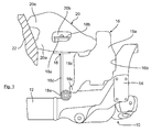
- the Fig. 1 shows in sections the corner region of a transverse spar 12 and a longitudinal spar 14 having subframe 10 per se known type, on which a suspension device or via a motor or assembly bearings 16, a parallel thereto arranged support bearing 18 and a subframe 20 an only indicated drive unit 22, for example, an internal combustion engine with attached speed change gearbox, is mounted vibration-damped.
- the suspension device may be part of a multi-point suspension, in particular a three-point suspension or a four-point suspension, the drive unit 22, wherein the illustrated suspension device may be used in mirror image the same on both sides of the internal combustion engine.
- the housing 16a of the assembly bearing 16 is here exemplary, but structurally and structurally or kraftpoundtechnisch particularly advantageous screwed at three attachment points fixed to the subframe 10, wherein two higher horizontally oriented and higher in vehicle vertical axis direction positioned attachment points formed by housing flanges 16b formed on the housing 16a (only one housing flange 16b is visible), while the third attachment point is formed by a lower housing arm 16c offset toward the vehicle center.
- the assembly bearing 16 is connected by means not shown fastening devices, preferably by screws, through the housing flanges 16b through with the longitudinal spar 14 and through the housing arm 16c through to the cross member 12 ecksteif firmly.
- the aggregate bearing 16 can be a hydraulically damped bearing of known type, which does not form the subject of the invention and therefore is not explained in detail.
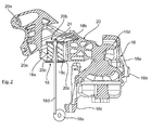
- the bearing core 16d ( Fig. 2 ) of the assembly bearing 16 is connected by means of a fastening device, not shown, for example by means of a screw, on the side projecting from the drive unit 22 subframe 20 at its outer end.
- connection or flange 20a (see also Fig. 3 ) with the drive unit 22 screwed together subframe 20 is here power flow technology favorable, as running away from the unit 22 outwardly tapering, arm-like hollow body.
- This hollow body is preferably made of a light metal alloy preferably produced in the casting process, in particular in the die-casting process (cf. Fig. 2 ), which rigidly carries the drive unit 22 by means of inner stiffening ribs and outer housing walls.
- a downwardly open cavity 20b is formed as a receiving space into which the support bearing 18 is at least partially, preferably substantially completely inserted.
- the support bearing 18 has a sleeve-shaped damping body 18a of preferably an elastomeric material with a defined configuration or spring stiffness, which is arranged between two, preferably vulcanized on the damping body, bearing plates 18b, 18c.
- the support plate 18 upwards conclusive bearing plate 18b is connected via a connecting device, here for example via a screw 24, with a damping body 18a (possibly leaving a radial gap) by projecting push rod 18d of the support bearing 18 firmly connected.
- the push rod 18d is aligned here according to a preferred embodiment perpendicular or in the direction of the vertical axis, but could also be aligned at an angle.
- the push rod 18d is articulated here for example via a lower bearing eye 18e and optionally a rubber-metal sleeve bearing in the near or in the remote region of the attachment point 16c of the unit bearing 16 on the cross member 12 of the subframe 10.
- the push rod 18d may also be rigidly connected there, e.g. be bolted.
- the lower bearing eye 18e or its bearing core can be screwed aligned in the vehicle longitudinal direction with the associated component. Should it be necessary for package or space reasons, but the screw can also be aligned at an angle.
- the lower bearing plate 18c of the support bearing 18 projects beyond, which in particular from Fig. 3 it can be seen, the edge regions 20c of the receiving or cavity 20b of the subframe 20 and is firmly connected to these, in particular screwed by means of screw connections 18f shown here only schematically.
- the lower bearing plate 18c here on a particularly advantageous oval shape, which does not completely closes or covers the cavity 20b from below. But if so should be required, for example, to protect against external influences, but the lower bearing plate 18c may also be designed so that it completely covers the cavity 20b or closes.
- the damping body 18a with the bearing plates 18b, 18c and optionally a surrounding housing but could also be pressed into the correspondingly adapted cavity 20b of the unit carrier 20, glued, etc. be.
- the suspension device may also be provided directly on the vehicle body or connected to corresponding structural elements.
- the support bearing 18 may also have a different construction.
Landscapes
- Engineering & Computer Science (AREA)
- Chemical & Material Sciences (AREA)
- Combustion & Propulsion (AREA)
- Transportation (AREA)
- Mechanical Engineering (AREA)
- Vibration Prevention Devices (AREA)
- Body Structure For Vehicles (AREA)
- Arrangement Or Mounting Of Propulsion Units For Vehicles (AREA)
- Vehicle Body Suspensions (AREA)
Abstract
Description
- Die vorliegende Erfindung betrifft eine Aufhängungsvorrichtung für Antriebsaggregate von Kraftfahrzeugen gemäß dem Oberbegriff des Patentanspruchs 1.
- Bei Aufhängungsvorrichtungen insbesondere für durch eine Brennkraftmaschine und ein Geschwindigkeits-Wechselgetriebe mit gegebenenfalls integriertem Achsdifferenzial angetriebene Kraftfahrzeuge (zum Beispiel mit Frontantrieb) können zu den meist hydraulisch gedämpften Aggregatelagern sogenannte Stützlager parallel geschaltet sein, die das Aufhängungssystem zusätzlich versteifen bzw. unzulässige Schwingungsspitzen zum Beispiel bei Lastwechseln des Kraftfahrzeugs vermeiden helfen.
- Eine gattungsgemäße Aufhängungsvorrichtung ist beispielsweise durch die
US 4,610,420 A bekannt, bei der das parallel zu einem Aggregatelager geschaltete Stützlager durch eine zwei Lageraugen aufweisende Stange gebildet ist, die über entsprechende Gummi-Metall-Hülsenlager mit dem Aggregateträger einerseits und einem Hilfsrahmen am Fahrzeugaufbau des Kraftfahrzeugs andererseits verbunden ist, wobei das Stützlager seitlich neben dem Aggregatelager positioniert ist und dementsprechenden Einbauraum im Kraftfahrzeug benötigt. - Aufgabe der Erfindung ist es, eine Aufhängungsvorrichtung mit einem Stützlager vorzuschlagen, die weniger Einbauraum erfordert und die baulich einfach und montagegünstig ausgeführt ist.
- Die Lösung dieser Aufgabe gelingt mit den Merkmalen des Patentanspruchs 1. Vorteilhafte und besonders zweckmäßige Weiterbildungen der Erfindung sind in den Unteransprüchen angeführt.
- Erfindungsgemäß wird vorgeschlagen, dass der Dämpfungskörper des Stützlagers wenigstens teilweise, bevorzugt im Wesentlichen vollständig, in den Aggregateträger integriert ist und über ein je nach Einbau- oder Belastungsrichtung als Zug- oder Druckstange ausgebildetes Stangen- bzw. Bauelement an den Fahrzeugaufbau mittelbar oder unmittelbar angeschlossen ist. Die Erfindung nutzt demzufolge den Aggregateträger durch entsprechende Gestaltung unmittelbar zur teilweisen Aufnahme des Stützlagers, das gegebenenfalls am Aggregateträger vormontiert montagegünstig verbaubar ist. Über die Zug- oder Druckstange wird das Stützlager dann in einfacher Weise an den Fahrzeugaufbau angeschlossen.
- Die Zug- oder Druckstange ist bevorzugt vertikal ausgerichtet, das heißt in Fahrzeughochachsenrichtung ausgerichtet, kann jedoch, falls dies aus Bauraumgründen oder aus Gründen eines Kraftflusses erforderlich sein sollte, auch winklig dazu ausgerichtet sein.
- Besonders bevorzugt kann der Aggregateträger, vorzugsweise ein durch Versteifungsrippen und Hohlräume mit Gehäusewänden ausgeführter Aggregateträger (vorzugsweise ein Gussteil), einen, zum Beispiel dem Fahrzeugaufbau zugewandten, offenen Hohlraum als Aufnahmeraum aufweisen, in dem der Dämpfungskörper, der vorzugsweise in nachfolgend noch näher beschriebener Weise zwischen Lagerplatten gehalten und/oder eingeschlossen ist, aufgenommen bzw. eingesetzt ist. Damit ist der Dämpfungskörper u.a. gut gegen äußere Einflüsse (zum Beispiel auch gegen Temperaturbelastungen durch angrenzende Aggregate oder Abgasleitungen) geschützt.
- Baulich besonders günstig kann die Zug- oder Druckstange den vorzugsweise hülsenförmigen Dämpfungskörper durchragen und mit dem Stützlager fest verbunden sein, zum Beispiel mit einer oberen Lagerplatte des Dämpfungskörpers fest verschraubt sein.
- Gemäß einer weiteren besonders bevorzugten erfindungsgemäßen Ausgestaltung weist das Stützlager eine Lagerplatte (insbesondere eine in Fahrzeughochachsenrichtung mit Bezug zum Hohlraum untere Lagerplatte) auf, die den Hohl- bzw. Aufnahmeraum und/oder diesen begrenzende Wandabschnitte randseitig bzw. flanschartig übergreift und mit dem Aggregatträger fest verbunden ist, insbesondere mit zugeordneten Wandabschnitten des Aggregatträgers verbunden bzw. verschraubt ist. Das Stützlager kann aber alternativ bzw. gegebenenfalls auch zusätzlich in den Hohlraum eingepresst oder anderweitig fest eingesetzt sein.
- In vorteilhafter Weiterbildung der Erfindung kann das Gehäuse des Aggregatelagers über eine Mehrpunktbefestigung, insbesondere über eine baulich sowie konstruktions- und kraftflusstechnisch besonders vorteilhafte Dreipunktbefestigung, mit einem am Fahrzeugaufbau angeordneten Hilfsrahmen fest verbunden sein, wobei wenigstens ein, vorzugsweise ein einziger, tiefer liegender, an einem Querholm des Hilfsrahmens festgelegter und zum Aggregateträger ragender Gehäusearm und mehrere, insbesondere zwei, demgegenüber in Fahrzeughochachsenrichtung höher positionierte, an einem Längsholm des Hilfsrahmens befestigte Gehäuseflansche vorgesehen sind. Besonders bevorzugt ist in diesem Zusammenhang eine Ausführungsform, bei der die Zug- oder Druckstange des Stützlagers, vorzugsweise unmittelbar benachbart zur Querholm-Anbindungsstelle des wenigstens eines Gehäusearms, an dem Querholm angebunden bzw. angelenkt ist. Alternativ dazu kann die Lagerstelle der Zug- oder Druckstange des Stützstegs aber auch wenigstens teilweise, bevorzugt vollständig, in den Gehäusearm integriert sein. Daraus resultiert eine besonders verwindungssteife Anbindung des Aggregatelagers und des Stützlagers an einen Hilfsrahmen bzw. über diesen an den Fahrzeugaufbau, die zudem montagegünstig herstellbar ist. Zudem lässt sich insbesondere mit der integrierten Lösung eine weitere Bauraumeinsparung erzielen.
- Schließlich kann der den Dämpfungskörper des Stützlagers aufnehmende Aggregateträger als Gussteil und/oder aus einer Leichtmetalllegierung hergestellt sein, wodurch die Integration des Stützlagers in den Aggregateträger nahezu ohne Mehraufwand möglich ist.
- Der Dämpfungskörper selbst weist bevorzugt einen Elastomerkörper mit definierter Federsteifigkeit auf oder ist durch einen solchen gebildet. Bevorzugt weist ein derartiger Elastomerkörper eine zentrale Durchgangsöffnung auf, durch den die Zug- oder Druckstange mit einem definierten Radialspalt oder konturangepasst und damit geführt hindurchgeführt ist. Auch eine hydraulische Dämpfung kann hier in Verbindung mit einem Dämpfungskörper vorgesehen sein.
- Ein Ausführungsbeispiel der Erfindung ist im Folgenden anhand der beigefügten, schematischen Zeichnung näher erläutert.
- Es zeigen:
- Fig. 1
- eine Frontansicht einer Aggregateaufhängung für ein Antriebsaggregat in Kraftfahrzeugen, mit teilweiser Darstellung eines Hilfsrahmens, an dem über ein Aggregatelager und ein Stützlager ein Aggregateträger abgestützt ist;
- Fig. 2
- einen Querschnitt durch den Aggregateträger, das Aggregatelager und das teilweise in den Aggregateträger integrierte Stützlager, jedoch ohne Hilfsrahmen;
- Fig. 3
- eine perspektivische Unteransicht des Aggregatträgers mit montierter unterer Lagerplatte.
- Die
Fig. 1 zeigt abschnittsweise den Eckbereich eines einen Querholm 12 und einen Längsholm 14 aufweisenden Hilfsrahmens 10 an sich bekannter Bauart, an dem über eine Aufhängungsvorrichtung bzw. über ein Motor- bzw. Aggregatelager 16, ein parallel dazu angeordnetes Stützlager 18 und einen Aggregateträger 20 ein nur angedeutetes Antriebsaggregat 22, zum Beispiel eine Brennkraftmaschine mit angeschlossenem Geschwindigkeits-Wechselgetriebe, schwingungsgedämpft gelagert ist. - Die Aufhängungsvorrichtung kann Teil einer Mehrpunktaufhängung, insbesondere einer Dreipunktaufhängung oder einer Vierpunktaufhängung, des Antriebsaggregats 22 sein, wobei an der Brennkraftmaschine an beiden Längsseiten die dargestellte Aufhängungsvorrichtung spiegelbildlich gleich verwendet sein kann.
- Das Gehäuse 16a des Aggregatelagers 16 ist hier beispielhaft, aber baulich und konstruktions- bzw. kraftflusstechnisch besonders vorteilhaft, an drei Befestigungspunkten fest mit dem Hilfsrahmen 10 verschraubt, wobei zwei etwa horizontal ausgerichtete und in Fahrzeughochachsenrichtung höher positionierte Befestigungspunkte durch am Gehäuse 16a angeformte Gehäuseflansche 16b (es ist nur ein Gehäuseflansch 16b ersichtlich) gebildet sind, während der dritte Befestigungspunkt durch einen unteren, zur Fahrzeugmitte hin versetzten Gehäusearm 16c gebildet ist.
- Das Aggregatelager 16 ist mittels nicht dargestellter Befestigungsvorrichtungen, vorzugsweise durch Schrauben, durch die Gehäuseflansche 16b hindurch mit dem Längsholm 14 und durch den Gehäusearm 16c hindurch mit dem Querträger 12 ecksteif fest verbunden.
- Das Aggregatelager 16 kann im Übrigen ein hydraulisch gedämpftes Lager bekannter Bauart sein, das nicht Gegenstand der Erfindung bildet und deshalb auch nicht näher erläutert ist. Der Lagerkern 16d (
Fig. 2 ) des Aggregatelagers 16 ist mittels einer nicht dargestellten Befestigungsvorrichtung, zum Beispiel mittels einer Schraubverbindung, an den seitlich vom Antriebsaggregat 22 abragenden Aggregateträger 20 an dessen äußeres Ende angeschlossen. - Der andererseits über Anschluss- bzw. Flanschbereiche 20a (siehe auch
Fig. 3 ) mit dem Antriebsaggregat 22 verschraubte Aggregateträger 20 ist hier kraftflusstechnisch günstig, als sich vom Aggregat 22 weg nach außen verjüngender, armartiger Hohlkörper ausgeführt. Dieser Hohlkörper ist bevorzugt aus einer vorzugsweise im Gussverfahren, insbesondere im Druckgussverfahren, hergestellten Leichtmetalllegierung ausgeführt (vergleicheFig. 2 ), der mittels innerer Versteifungsrippen und äußeren Gehäusewänden biegesteif das Antriebsaggregat 22 trägt. - In dem Aggregateträger 20 ist zudem ein nach unten offener Hohlraum 20b als Aufnahmeraum eingeformt, in den das Stützlager 18 zumindest teilweise, vorzugsweise im Wesentlichen vollständig eingesetzt ist.
- Das Stützlager 18 weist einen hülsenförmigen Dämpfungskörper 18a aus vorzugsweise einem Elastomermaterial mit definierter Konfiguration bzw. Federsteifigkeit auf, der zwischen zwei, vorzugsweise am Dämpfungskörper anvulkanisierten, Lagerplatten 18b, 18c angeordnet ist.
- Die das Stützlager 18 nach oben abschließende Lagerplatte 18b ist über eine Verbindungseinrichtung, hier beispielhaft über eine Schraubverbindung 24, mit einer den Dämpfungskörper 18a (gegebenenfalls unter Belassung eines Radialspaltes) durchragenden Druckstange 18d des Stützlagers 18 fest verbunden. Die Druckstange 18d ist hier gemäß einer bevorzugten Ausgestaltung senkrecht bzw. in Hochachsenrichtung ausgerichtet, könnte jedoch auch winklig ausgerichtet sein. Ferner ist die Druckstange 18d hier beispielhaft über ein unteres Lagerauge 18e und gegebenenfalls ein Gummi-Metall-Hülsenlager im nahen oder auch im entfernten Bereich des Befestigungspunkts 16c des Aggregatelagers 16 an dem Querholm 12 des Hilfsrahmens 10 angelenkt. Alternativ kann die Druckstange 18d dort aber auch starr angebunden sein, z.B. verschraubt sein.
- Das untere Lagerauge 18e bzw. dessen Lagerkern kann in Fahrzeuglängsrichtung ausgerichtet mit dem zugeordneten Bauteil verschraubt sein. Sollte es aus Package- oder Bauraumgründen erforderlich sein, kann die Verschraubung aber auch hierzu winklig ausgerichtet sein.
- Die untere Lagerplatte 18c des Stützlagers 18 überragt, was insbesondere aus der
Fig. 3 ersichtlich ist, die Randbereiche 20c des Aufnahme- bzw. Hohlraums 20b des Aggregateträgers 20 und ist mit diesen fest verbunden, insbesondere mittels hier lediglich schematisch dargestellter Schraubverbindungen 18f verschraubt. Wie in derFig. 3 weiter dargestellt weist die untere Lagerplatte 18c hier eine besonders vorteilhafte ovale Form auf, die den Hohlraum 20b von unten her nicht vollständig verschließt bzw. abdeckt. Falls dies aber erforderlich sein sollte, zum Beispiel zum Schutz gegen äußere Einflüsse, kann die untere Lagerplatte 18c aber auch so ausgebildet sein, dass diese den Hohlraum 20b vollständig abdeckt bzw. verschließt. Der Dämpfungskörper 18a mit den Lagerplatten 18b, 18c und gegebenenfalls einem umgebenden Gehäuse könnte aber auch in den entsprechend angepassten Hohlraum 20b des Aggregateträgers 20 eingepresst, eingeklebt, etc. sein. - Durch die parallele und besonders anbindungssteife Anordnung des in den Aggregateträger 20 integrierten Stützlagers 18 zum Aggregatelager 16 wird dessen Dämpfungsfunktion wirkungsvoll der Dämpfungsfunktion des Aggregatelagers 16 überlagert und werden gegebenenfalls auftretende, unzulässige Schwingungsspitzen zuverlässig absorbiert.
- Die Erfindung ist nicht auf das dargestellte Ausführungsbeispiel beschränkt. Insbesondere sind im Rahmen der formulierten Ansprüche auch dem Fachmann geläufige Abwandlungen möglich.
- Anstelle des Hilfsrahmens 10 kann die Aufhängungsvorrichtung auch unmittelbar am Fahrzeugaufbau vorgesehen sein bzw. mit entsprechenden Aufbauelementen verbunden sein. Gegebenenfalls kann das Stützlager 18 auch eine andere Konstruktion aufweisen.
Claims (8)
- Aufhängungsvorrichtung für Antriebsaggregate (22) von Kraftfahrzeugen, mit einem schwingungsdämpfenden Aggregatelager (16), dessen Gehäuse (16a) am Fahrzeugaufbau (10) abgestützt ist und an dessen Lagerkern (16d) ein am Antriebsaggregat (22) festgelegter Aggregateträger (20) angeschlossen ist, sowie mit einem parallel zum Aggregatelager (16) vorgesehenen Stützlager (18), dessen Dämpfungskörper (18a) einerseits an dem Aggregateträger (20) und andererseits an dem Fahrzeugaufbau (10) angeschlossen ist, dadurch gekennzeichnet, dass der Dämpfungskörper (18a) des Stützlagers (18) wenigstens teilweise in den Aggregateträger (20) integriert ist und über eine Zug- oder Druckstange (18d) an den Fahrzeugaufbau (10) mittelbar oder unmittelbar angeschlossen ist.
- Aufhängungsvorrichtung nach Anspruch 1, dadurch gekennzeichnet, dass der Aggregateträger (20) einen offenen Hohlraum (20b) als Aufnahmeraum aufweist, in dem der Dämpfungskörper (18a) aufgenommen und/oder eingesetzt ist.
- Aufhängungsvorrichtung nach den Ansprüchen 1 oder 2, dadurch gekennzeichnet, dass die Zug- oder Druckstange (18d) den Dämpfungskörper (18a) durchragt und mit dem Stützlager (18) verbunden ist.
- Aufhängungsvorrichtung nach Anspruch 3, dadurch gekennzeichnet, dass das Stützlager (18) eine Lagerplatte (18c) aufweist, die den Hohlraum (20b) und/oder diesen begrenzende Wandabschnitte (20c) flanschartig übergreift und mit dem Aggregateträger (20) verbunden ist.
- Aufhängungsvorrichtung nach einem der vorhergehenden Ansprüche, dadurch gekennzeichnet, dass das Gehäuse (16a) des Aggregatelagers (16) über eine Mehrpunktbefestigung mit einem am Fahrzeugaufbau angeordneten Hilfsrahmen (10) fest verbunden ist, wobei wenigstens eintiefer liegender, an einem Querholm (12) des Hilfsrahmens (10) festgelegter und zum Aggregateträger (20) ragender Gehäusearm (16c) und mehrere demgegenüber in Fahrzeughochachsenrichtung höher positionierte, an einem Längsholm (14) des Hilfsrahmens (10) befestigte Gehäuseflansche (16b) vorgesehen sind.
- Aufhängungsvorrichtung nach Anspruch 5, dadurch gekennzeichnet, dass die Zug- oder Druckstange (18d) des Stützlagers (18) an dem Querholm (12) angebunden ist oder dass eine Lagerstelle (18e) der Zug- oder Druckstange (18d) des Stützstegs (18) wenigstens teilweise in den Gehäusearm (16c) integriert ist.
- Aufhängungsvorrichtung nach einem der vorhergehenden Ansprüche, dadurch gekennzeichnet, dass der den Dämpfungskörper (18a) des Stützlagers (18) aufnehmende Aggregateträger (20) als Gussteil und/oder aus einer Leichtmetalllegierung hergestellt ist.
- Aufhängungsvorrichtung nach einem der vorhergehenden Ansprüche, dadurch gekennzeichnet, dass der Dämpfungskörper (18a) einen Elastomerkörper mit definierter Federsteifigkeit aufweist oder durch einen solchen gebildet ist, der eine zentrale Durchgangsöffnung aufweist, durch den die Zug- oder Druckstange (18d) mit einem definierten Radialspalt oder konturangepasst hindurchgeführt ist.
Applications Claiming Priority (1)
| Application Number | Priority Date | Filing Date | Title |
|---|---|---|---|
| DE102013007473.8A DE102013007473B4 (de) | 2013-04-30 | 2013-04-30 | Aufhängungsvorrichtung für Antriebsaggregate von Kraftfahrzeugen |
Publications (3)
| Publication Number | Publication Date |
|---|---|
| EP2799269A2 true EP2799269A2 (de) | 2014-11-05 |
| EP2799269A3 EP2799269A3 (de) | 2015-07-29 |
| EP2799269B1 EP2799269B1 (de) | 2020-01-15 |
Family
ID=50549048
Family Applications (1)
| Application Number | Title | Priority Date | Filing Date |
|---|---|---|---|
| EP14166207.2A Active EP2799269B1 (de) | 2013-04-30 | 2014-04-28 | Aufhängungsvorrichtung für antriebsaggregate von kraftfahrzeugen |
Country Status (3)
| Country | Link |
|---|---|
| EP (1) | EP2799269B1 (de) |
| CN (1) | CN104129265B (de) |
| DE (1) | DE102013007473B4 (de) |
Families Citing this family (5)
| Publication number | Priority date | Publication date | Assignee | Title |
|---|---|---|---|---|
| DE102017219789A1 (de) * | 2017-11-07 | 2019-05-09 | Bayerische Motoren Werke Aktiengesellschaft | Getriebebaugruppe |
| DE102019100906B4 (de) * | 2019-01-15 | 2020-08-06 | Bayerische Motoren Werke Aktiengesellschaft | Vorderwagenstruktur für ein Kraftfahrzeug, insbesondere für einen Personenkraftwagen, sowie Kraftfahrzeug, insbesondere Personenkraftwagen |
| DE102019206519B4 (de) * | 2019-05-07 | 2021-02-25 | Audi Ag | Aggregatelagerung in einem Fahrzeug |
| CN112406502B (zh) * | 2020-11-04 | 2022-03-29 | 东风越野车有限公司 | 一种发动机悬置与前驱动桥集成式布置结构 |
| DE102022103312A1 (de) | 2022-02-11 | 2023-08-17 | Audi Aktiengesellschaft | Hilfsrahmen für ein Fahrzeug |
Citations (1)
| Publication number | Priority date | Publication date | Assignee | Title |
|---|---|---|---|---|
| US4610420A (en) | 1984-02-16 | 1986-09-09 | Nissan Motor Company, Limited | Apparatus for mounting power unit |
Family Cites Families (7)
| Publication number | Priority date | Publication date | Assignee | Title |
|---|---|---|---|---|
| JPS5690725A (en) * | 1979-12-20 | 1981-07-23 | Nissan Motor Co Ltd | Mounting device for engine |
| JPS56124513A (en) * | 1980-02-29 | 1981-09-30 | Nissan Motor Co Ltd | Mounting device of engine |
| FR2744677B1 (fr) * | 1996-02-09 | 1998-03-06 | Peugeot | Dispositif de suspension d'un groupe moto-propulseur de vehicule automobile, comportant une biellette anti-couple |
| FR2831111B1 (fr) * | 2001-10-23 | 2004-01-09 | Renault | Systeme de fixation d'un groupe motopropulseur dans un vehicule |
| CN201300707Y (zh) * | 2008-10-21 | 2009-09-02 | 奇瑞汽车股份有限公司 | 一种动力总成悬置系统 |
| CN101850712A (zh) * | 2010-03-30 | 2010-10-06 | 重庆长安汽车股份有限公司 | 一种具有吸振功能的汽车动力总成悬置软垫 |
| JP5652704B2 (ja) * | 2010-09-15 | 2015-01-14 | スズキ株式会社 | 車両のトルクロッド配設構造 |
-
2013
- 2013-04-30 DE DE102013007473.8A patent/DE102013007473B4/de not_active Expired - Fee Related
-
2014
- 2014-04-28 EP EP14166207.2A patent/EP2799269B1/de active Active
- 2014-04-30 CN CN201410180971.9A patent/CN104129265B/zh active Active
Patent Citations (1)
| Publication number | Priority date | Publication date | Assignee | Title |
|---|---|---|---|---|
| US4610420A (en) | 1984-02-16 | 1986-09-09 | Nissan Motor Company, Limited | Apparatus for mounting power unit |
Also Published As
| Publication number | Publication date |
|---|---|
| DE102013007473A1 (de) | 2014-10-30 |
| EP2799269B1 (de) | 2020-01-15 |
| CN104129265B (zh) | 2017-01-11 |
| EP2799269A3 (de) | 2015-07-29 |
| DE102013007473B4 (de) | 2017-06-08 |
| CN104129265A (zh) | 2014-11-05 |
Similar Documents
| Publication | Publication Date | Title |
|---|---|---|
| DE102013007473B4 (de) | Aufhängungsvorrichtung für Antriebsaggregate von Kraftfahrzeugen | |
| EP3181390B1 (de) | Fahrzeug mit einem antriebsaggregat und einer aggregatelagerung | |
| DE102010020304A1 (de) | Hilfsträger | |
| DE102009036495A1 (de) | Rohbauteil eines Rohbaus für eine Fahrzeugkarosserie und Rohbau einer Fahrzeugkarosserie | |
| DE102016009395B4 (de) | Lagerungsanordnung eines elektrischen Antriebsstrangs an einem Kraftwagenrohbau | |
| DE102013011546A1 (de) | Hilfsrahmen für ein Kraftfahrzeug | |
| EP2991846B1 (de) | Aggregatelageranordnung für kraftfahrzeuge | |
| DE102012017319B4 (de) | Befestigungsanordnung zwischen einem Radiallager und einem Stützarm | |
| DE102014113565A1 (de) | Versteifungselement | |
| DE102012107501A1 (de) | Druckvorrichtung für eine Zahnstange in einem Lenkgetriebe | |
| DE102012014477B4 (de) | Lagerungsanordnung | |
| DE19849770A1 (de) | Gabelstapler | |
| WO2020169404A1 (de) | Radsatzgetriebe | |
| EP2289772B1 (de) | Vorrichtung zur Verbindung eines Trägerlements mit einem Gussbauteil | |
| DE102006056225A1 (de) | Halteeinrichtung für einen Lastkraftwagen | |
| DE102015213262A1 (de) | Kraftfahrzeug mit einem Frontendmodul | |
| DE19600441A1 (de) | Zylinderkopf einer Brennkraftmaschine | |
| EP3873791B1 (de) | Fahrzeug mit einer tragstruktur | |
| EP2383137B1 (de) | Aggregateaufhängung, insbesondere für Kraftfahrzeuge | |
| DE102004062083A1 (de) | Anordnung zumindest eines Aggregatelagers an einem Hilfsrahmen | |
| DE102012015334A1 (de) | Befestigungsanordnung einer Versteifungsstrebe an einem Windschutzscheiben-Querträger | |
| DE102010005763A1 (de) | Lager | |
| DE102010046768A1 (de) | Verbindungsanordnung von zwei Bauteilen über eine Schraubverbindung | |
| DE602006000834T2 (de) | Antriebsaggregat mit Geräuschdämpfungsvorrichtung | |
| DE102008026705A1 (de) | Motorrad mit einer Hinterradlagerung und einer Dämpfungseinrichtung zur Dämpfung von Pendelschwingungen |
Legal Events
| Date | Code | Title | Description |
|---|---|---|---|
| PUAI | Public reference made under article 153(3) epc to a published international application that has entered the european phase |
Free format text: ORIGINAL CODE: 0009012 |
|
| 17P | Request for examination filed |
Effective date: 20140428 |
|
| AK | Designated contracting states |
Kind code of ref document: A2 Designated state(s): AL AT BE BG CH CY CZ DE DK EE ES FI FR GB GR HR HU IE IS IT LI LT LU LV MC MK MT NL NO PL PT RO RS SE SI SK SM TR |
|
| AX | Request for extension of the european patent |
Extension state: BA ME |
|
| PUAL | Search report despatched |
Free format text: ORIGINAL CODE: 0009013 |
|
| AK | Designated contracting states |
Kind code of ref document: A3 Designated state(s): AL AT BE BG CH CY CZ DE DK EE ES FI FR GB GR HR HU IE IS IT LI LT LU LV MC MK MT NL NO PL PT RO RS SE SI SK SM TR |
|
| AX | Request for extension of the european patent |
Extension state: BA ME |
|
| RIC1 | Information provided on ipc code assigned before grant |
Ipc: B60K 5/12 20060101AFI20150623BHEP |
|
| R17P | Request for examination filed (corrected) |
Effective date: 20160129 |
|
| RBV | Designated contracting states (corrected) |
Designated state(s): AL AT BE BG CH CY CZ DE DK EE ES FI FR GB GR HR HU IE IS IT LI LT LU LV MC MK MT NL NO PL PT RO RS SE SI SK SM TR |
|
| RIN1 | Information on inventor provided before grant (corrected) |
Inventor name: VOLLMANN, STEFAN Inventor name: BUJAK, MAREK Inventor name: VOGEL, FRIEDEMANN |
|
| RIN1 | Information on inventor provided before grant (corrected) |
Inventor name: VOLLMANN, STEFAN Inventor name: VOGEL, FRIEDEMANN Inventor name: BUJAK, MAREK |
|
| GRAP | Despatch of communication of intention to grant a patent |
Free format text: ORIGINAL CODE: EPIDOSNIGR1 |
|
| STAA | Information on the status of an ep patent application or granted ep patent |
Free format text: STATUS: GRANT OF PATENT IS INTENDED |
|
| INTG | Intention to grant announced |
Effective date: 20191002 |
|
| GRAS | Grant fee paid |
Free format text: ORIGINAL CODE: EPIDOSNIGR3 |
|
| GRAA | (expected) grant |
Free format text: ORIGINAL CODE: 0009210 |
|
| STAA | Information on the status of an ep patent application or granted ep patent |
Free format text: STATUS: THE PATENT HAS BEEN GRANTED |
|
| AK | Designated contracting states |
Kind code of ref document: B1 Designated state(s): AL AT BE BG CH CY CZ DE DK EE ES FI FR GB GR HR HU IE IS IT LI LT LU LV MC MK MT NL NO PL PT RO RS SE SI SK SM TR |
|
| REG | Reference to a national code |
Ref country code: CH Ref legal event code: EP Ref country code: GB Ref legal event code: FG4D Free format text: NOT ENGLISH |
|
| REG | Reference to a national code |
Ref country code: IE Ref legal event code: FG4D Free format text: LANGUAGE OF EP DOCUMENT: GERMAN |
|
| REG | Reference to a national code |
Ref country code: DE Ref legal event code: R096 Ref document number: 502014013457 Country of ref document: DE |
|
| REG | Reference to a national code |
Ref country code: AT Ref legal event code: REF Ref document number: 1224863 Country of ref document: AT Kind code of ref document: T Effective date: 20200215 |
|
| REG | Reference to a national code |
Ref country code: NL Ref legal event code: MP Effective date: 20200115 |
|
| REG | Reference to a national code |
Ref country code: LT Ref legal event code: MG4D |
|
| PG25 | Lapsed in a contracting state [announced via postgrant information from national office to epo] |
Ref country code: FI Free format text: LAPSE BECAUSE OF FAILURE TO SUBMIT A TRANSLATION OF THE DESCRIPTION OR TO PAY THE FEE WITHIN THE PRESCRIBED TIME-LIMIT Effective date: 20200115 Ref country code: PT Free format text: LAPSE BECAUSE OF FAILURE TO SUBMIT A TRANSLATION OF THE DESCRIPTION OR TO PAY THE FEE WITHIN THE PRESCRIBED TIME-LIMIT Effective date: 20200607 Ref country code: NL Free format text: LAPSE BECAUSE OF FAILURE TO SUBMIT A TRANSLATION OF THE DESCRIPTION OR TO PAY THE FEE WITHIN THE PRESCRIBED TIME-LIMIT Effective date: 20200115 Ref country code: RS Free format text: LAPSE BECAUSE OF FAILURE TO SUBMIT A TRANSLATION OF THE DESCRIPTION OR TO PAY THE FEE WITHIN THE PRESCRIBED TIME-LIMIT Effective date: 20200115 Ref country code: NO Free format text: LAPSE BECAUSE OF FAILURE TO SUBMIT A TRANSLATION OF THE DESCRIPTION OR TO PAY THE FEE WITHIN THE PRESCRIBED TIME-LIMIT Effective date: 20200415 |
|
| PG25 | Lapsed in a contracting state [announced via postgrant information from national office to epo] |
Ref country code: GR Free format text: LAPSE BECAUSE OF FAILURE TO SUBMIT A TRANSLATION OF THE DESCRIPTION OR TO PAY THE FEE WITHIN THE PRESCRIBED TIME-LIMIT Effective date: 20200416 Ref country code: BG Free format text: LAPSE BECAUSE OF FAILURE TO SUBMIT A TRANSLATION OF THE DESCRIPTION OR TO PAY THE FEE WITHIN THE PRESCRIBED TIME-LIMIT Effective date: 20200415 Ref country code: HR Free format text: LAPSE BECAUSE OF FAILURE TO SUBMIT A TRANSLATION OF THE DESCRIPTION OR TO PAY THE FEE WITHIN THE PRESCRIBED TIME-LIMIT Effective date: 20200115 Ref country code: SE Free format text: LAPSE BECAUSE OF FAILURE TO SUBMIT A TRANSLATION OF THE DESCRIPTION OR TO PAY THE FEE WITHIN THE PRESCRIBED TIME-LIMIT Effective date: 20200115 Ref country code: LV Free format text: LAPSE BECAUSE OF FAILURE TO SUBMIT A TRANSLATION OF THE DESCRIPTION OR TO PAY THE FEE WITHIN THE PRESCRIBED TIME-LIMIT Effective date: 20200115 Ref country code: IS Free format text: LAPSE BECAUSE OF FAILURE TO SUBMIT A TRANSLATION OF THE DESCRIPTION OR TO PAY THE FEE WITHIN THE PRESCRIBED TIME-LIMIT Effective date: 20200515 |
|
| REG | Reference to a national code |
Ref country code: DE Ref legal event code: R097 Ref document number: 502014013457 Country of ref document: DE |
|
| PG25 | Lapsed in a contracting state [announced via postgrant information from national office to epo] |
Ref country code: ES Free format text: LAPSE BECAUSE OF FAILURE TO SUBMIT A TRANSLATION OF THE DESCRIPTION OR TO PAY THE FEE WITHIN THE PRESCRIBED TIME-LIMIT Effective date: 20200115 Ref country code: CZ Free format text: LAPSE BECAUSE OF FAILURE TO SUBMIT A TRANSLATION OF THE DESCRIPTION OR TO PAY THE FEE WITHIN THE PRESCRIBED TIME-LIMIT Effective date: 20200115 Ref country code: RO Free format text: LAPSE BECAUSE OF FAILURE TO SUBMIT A TRANSLATION OF THE DESCRIPTION OR TO PAY THE FEE WITHIN THE PRESCRIBED TIME-LIMIT Effective date: 20200115 Ref country code: DK Free format text: LAPSE BECAUSE OF FAILURE TO SUBMIT A TRANSLATION OF THE DESCRIPTION OR TO PAY THE FEE WITHIN THE PRESCRIBED TIME-LIMIT Effective date: 20200115 Ref country code: SM Free format text: LAPSE BECAUSE OF FAILURE TO SUBMIT A TRANSLATION OF THE DESCRIPTION OR TO PAY THE FEE WITHIN THE PRESCRIBED TIME-LIMIT Effective date: 20200115 Ref country code: EE Free format text: LAPSE BECAUSE OF FAILURE TO SUBMIT A TRANSLATION OF THE DESCRIPTION OR TO PAY THE FEE WITHIN THE PRESCRIBED TIME-LIMIT Effective date: 20200115 Ref country code: SK Free format text: LAPSE BECAUSE OF FAILURE TO SUBMIT A TRANSLATION OF THE DESCRIPTION OR TO PAY THE FEE WITHIN THE PRESCRIBED TIME-LIMIT Effective date: 20200115 Ref country code: LT Free format text: LAPSE BECAUSE OF FAILURE TO SUBMIT A TRANSLATION OF THE DESCRIPTION OR TO PAY THE FEE WITHIN THE PRESCRIBED TIME-LIMIT Effective date: 20200115 |
|
| PLBE | No opposition filed within time limit |
Free format text: ORIGINAL CODE: 0009261 |
|
| STAA | Information on the status of an ep patent application or granted ep patent |
Free format text: STATUS: NO OPPOSITION FILED WITHIN TIME LIMIT |
|
| PG25 | Lapsed in a contracting state [announced via postgrant information from national office to epo] |
Ref country code: MC Free format text: LAPSE BECAUSE OF FAILURE TO SUBMIT A TRANSLATION OF THE DESCRIPTION OR TO PAY THE FEE WITHIN THE PRESCRIBED TIME-LIMIT Effective date: 20200115 |
|
| REG | Reference to a national code |
Ref country code: CH Ref legal event code: PL |
|
| 26N | No opposition filed |
Effective date: 20201016 |
|
| PG25 | Lapsed in a contracting state [announced via postgrant information from national office to epo] |
Ref country code: IT Free format text: LAPSE BECAUSE OF FAILURE TO SUBMIT A TRANSLATION OF THE DESCRIPTION OR TO PAY THE FEE WITHIN THE PRESCRIBED TIME-LIMIT Effective date: 20200115 Ref country code: CH Free format text: LAPSE BECAUSE OF NON-PAYMENT OF DUE FEES Effective date: 20200430 Ref country code: LI Free format text: LAPSE BECAUSE OF NON-PAYMENT OF DUE FEES Effective date: 20200430 Ref country code: LU Free format text: LAPSE BECAUSE OF NON-PAYMENT OF DUE FEES Effective date: 20200428 |
|
| REG | Reference to a national code |
Ref country code: BE Ref legal event code: MM Effective date: 20200430 |
|
| PG25 | Lapsed in a contracting state [announced via postgrant information from national office to epo] |
Ref country code: PL Free format text: LAPSE BECAUSE OF FAILURE TO SUBMIT A TRANSLATION OF THE DESCRIPTION OR TO PAY THE FEE WITHIN THE PRESCRIBED TIME-LIMIT Effective date: 20200115 Ref country code: BE Free format text: LAPSE BECAUSE OF NON-PAYMENT OF DUE FEES Effective date: 20200430 Ref country code: SI Free format text: LAPSE BECAUSE OF FAILURE TO SUBMIT A TRANSLATION OF THE DESCRIPTION OR TO PAY THE FEE WITHIN THE PRESCRIBED TIME-LIMIT Effective date: 20200115 |
|
| PG25 | Lapsed in a contracting state [announced via postgrant information from national office to epo] |
Ref country code: IE Free format text: LAPSE BECAUSE OF NON-PAYMENT OF DUE FEES Effective date: 20200428 |
|
| REG | Reference to a national code |
Ref country code: AT Ref legal event code: MM01 Ref document number: 1224863 Country of ref document: AT Kind code of ref document: T Effective date: 20200428 |
|
| PG25 | Lapsed in a contracting state [announced via postgrant information from national office to epo] |
Ref country code: AT Free format text: LAPSE BECAUSE OF NON-PAYMENT OF DUE FEES Effective date: 20200428 |
|
| PG25 | Lapsed in a contracting state [announced via postgrant information from national office to epo] |
Ref country code: TR Free format text: LAPSE BECAUSE OF FAILURE TO SUBMIT A TRANSLATION OF THE DESCRIPTION OR TO PAY THE FEE WITHIN THE PRESCRIBED TIME-LIMIT Effective date: 20200115 Ref country code: MT Free format text: LAPSE BECAUSE OF FAILURE TO SUBMIT A TRANSLATION OF THE DESCRIPTION OR TO PAY THE FEE WITHIN THE PRESCRIBED TIME-LIMIT Effective date: 20200115 Ref country code: CY Free format text: LAPSE BECAUSE OF FAILURE TO SUBMIT A TRANSLATION OF THE DESCRIPTION OR TO PAY THE FEE WITHIN THE PRESCRIBED TIME-LIMIT Effective date: 20200115 |
|
| PG25 | Lapsed in a contracting state [announced via postgrant information from national office to epo] |
Ref country code: MK Free format text: LAPSE BECAUSE OF FAILURE TO SUBMIT A TRANSLATION OF THE DESCRIPTION OR TO PAY THE FEE WITHIN THE PRESCRIBED TIME-LIMIT Effective date: 20200115 Ref country code: AL Free format text: LAPSE BECAUSE OF FAILURE TO SUBMIT A TRANSLATION OF THE DESCRIPTION OR TO PAY THE FEE WITHIN THE PRESCRIBED TIME-LIMIT Effective date: 20200115 |
|
| P01 | Opt-out of the competence of the unified patent court (upc) registered |
Effective date: 20230530 |
|
| PGFP | Annual fee paid to national office [announced via postgrant information from national office to epo] |
Ref country code: DE Payment date: 20250430 Year of fee payment: 12 |
|
| PGFP | Annual fee paid to national office [announced via postgrant information from national office to epo] |
Ref country code: GB Payment date: 20250426 Year of fee payment: 12 |
|
| PGFP | Annual fee paid to national office [announced via postgrant information from national office to epo] |
Ref country code: FR Payment date: 20250426 Year of fee payment: 12 |