EP2799097A2 - Device for treating blood outside the body - Google Patents
Device for treating blood outside the body Download PDFInfo
- Publication number
- EP2799097A2 EP2799097A2 EP14165194.3A EP14165194A EP2799097A2 EP 2799097 A2 EP2799097 A2 EP 2799097A2 EP 14165194 A EP14165194 A EP 14165194A EP 2799097 A2 EP2799097 A2 EP 2799097A2
- Authority
- EP
- European Patent Office
- Prior art keywords
- dialysis fluid
- filter element
- detection device
- equal
- preferably less
- Prior art date
- Legal status (The legal status is an assumption and is not a legal conclusion. Google has not performed a legal analysis and makes no representation as to the accuracy of the status listed.)
- Granted
Links
- 0 C*(CCCCN1CC1)O Chemical compound C*(CCCCN1CC1)O 0.000 description 1
Images


Classifications
-
- A—HUMAN NECESSITIES
- A61—MEDICAL OR VETERINARY SCIENCE; HYGIENE
- A61M—DEVICES FOR INTRODUCING MEDIA INTO, OR ONTO, THE BODY; DEVICES FOR TRANSDUCING BODY MEDIA OR FOR TAKING MEDIA FROM THE BODY; DEVICES FOR PRODUCING OR ENDING SLEEP OR STUPOR
- A61M1/00—Suction or pumping devices for medical purposes; Devices for carrying-off, for treatment of, or for carrying-over, body-liquids; Drainage systems
- A61M1/14—Dialysis systems; Artificial kidneys; Blood oxygenators ; Reciprocating systems for treatment of body fluids, e.g. single needle systems for hemofiltration or pheresis
- A61M1/16—Dialysis systems; Artificial kidneys; Blood oxygenators ; Reciprocating systems for treatment of body fluids, e.g. single needle systems for hemofiltration or pheresis with membranes
- A61M1/1601—Control or regulation
- A61M1/1603—Regulation parameters
- A61M1/1605—Physical characteristics of the dialysate fluid
- A61M1/1609—Physical characteristics of the dialysate fluid after use, i.e. downstream of dialyser
-
- A—HUMAN NECESSITIES
- A61—MEDICAL OR VETERINARY SCIENCE; HYGIENE
- A61M—DEVICES FOR INTRODUCING MEDIA INTO, OR ONTO, THE BODY; DEVICES FOR TRANSDUCING BODY MEDIA OR FOR TAKING MEDIA FROM THE BODY; DEVICES FOR PRODUCING OR ENDING SLEEP OR STUPOR
- A61M1/00—Suction or pumping devices for medical purposes; Devices for carrying-off, for treatment of, or for carrying-over, body-liquids; Drainage systems
- A61M1/14—Dialysis systems; Artificial kidneys; Blood oxygenators ; Reciprocating systems for treatment of body fluids, e.g. single needle systems for hemofiltration or pheresis
- A61M1/16—Dialysis systems; Artificial kidneys; Blood oxygenators ; Reciprocating systems for treatment of body fluids, e.g. single needle systems for hemofiltration or pheresis with membranes
- A61M1/1601—Control or regulation
- A61M1/1617—Control or regulation using measurements made during a temporary variation of a characteristic of the fresh dialysis fluid
-
- B—PERFORMING OPERATIONS; TRANSPORTING
- B01—PHYSICAL OR CHEMICAL PROCESSES OR APPARATUS IN GENERAL
- B01D—SEPARATION
- B01D61/00—Processes of separation using semi-permeable membranes, e.g. dialysis, osmosis or ultrafiltration; Apparatus, accessories or auxiliary operations specially adapted therefor
- B01D61/24—Dialysis ; Membrane extraction
- B01D61/30—Accessories; Auxiliary operation
-
- B—PERFORMING OPERATIONS; TRANSPORTING
- B01—PHYSICAL OR CHEMICAL PROCESSES OR APPARATUS IN GENERAL
- B01D—SEPARATION
- B01D61/00—Processes of separation using semi-permeable membranes, e.g. dialysis, osmosis or ultrafiltration; Apparatus, accessories or auxiliary operations specially adapted therefor
- B01D61/24—Dialysis ; Membrane extraction
- B01D61/32—Controlling or regulating
-
- A—HUMAN NECESSITIES
- A61—MEDICAL OR VETERINARY SCIENCE; HYGIENE
- A61M—DEVICES FOR INTRODUCING MEDIA INTO, OR ONTO, THE BODY; DEVICES FOR TRANSDUCING BODY MEDIA OR FOR TAKING MEDIA FROM THE BODY; DEVICES FOR PRODUCING OR ENDING SLEEP OR STUPOR
- A61M2202/00—Special media to be introduced, removed or treated
- A61M2202/04—Liquids
- A61M2202/0496—Urine
- A61M2202/0498—Urea
-
- A—HUMAN NECESSITIES
- A61—MEDICAL OR VETERINARY SCIENCE; HYGIENE
- A61M—DEVICES FOR INTRODUCING MEDIA INTO, OR ONTO, THE BODY; DEVICES FOR TRANSDUCING BODY MEDIA OR FOR TAKING MEDIA FROM THE BODY; DEVICES FOR PRODUCING OR ENDING SLEEP OR STUPOR
- A61M2205/00—General characteristics of the apparatus
- A61M2205/33—Controlling, regulating or measuring
- A61M2205/3306—Optical measuring means
- A61M2205/3313—Optical measuring means used specific wavelengths
Definitions
- a classic method is the chemical determination of urea concentration in the blood before and after a dialysis therapy.
- the problem with this method is that the blood samples are taken from the patient and sent to a laboratory which is appropriately equipped for the determination of the urea concentration. This process can take several days. Accordingly, the determination of the dialysis dose can not take place promptly and, above all, not during a dialysis session.
- the invention is based on a measuring device for the determination of waste products in dialysis fluids during dialysis treatments, as described in particular in the EP 1 083 948 B1 in which the structure and the position of the known measuring device (sensor) for dialysis technology applications are explained.
- the following statements relate essentially to a UV sensor in dialysis, as in the EP 1 083 948 B1 described.
- Such UV sensors are nowadays integrated in many modern dialysis machines. Their position has remained essentially unchanged since the market launch of such systems. They are located in the outflow of dialysis fluid, usually downstream of the balancing device, ie downstream of the balancing device.
- u z is the velocity of the liquid along the channel or tube
- ⁇ is the viscosity of the liquid
- ⁇ ⁇ ⁇ z is the pressure gradient
- R is the internal diameter of the duct or hose
- r is the radial distance of the point under consideration from the center of the duct or hose.
- u z 0.
- Q is the volume flow (flow) of the medium in the duct or hose.
- This effect due to the flow profile affects the quality of measurements that have to be made within a certain time after the pulse has developed. This can be the case, for example, if a control algorithm requires a data value in short time intervals or if only a short concentration pulse is available for the measurement.
- an advantageous positioning of the detection device 14 or 14a is given if the hose / line volume between the filter element outlet and the detection device 14 or 14a is less than or equal to 100 ml, preferably less than or equal to 50 ml, preferably less than or equal to 35 ml, preferably less than or equal to 30 ml, preferably less than or equal to 15 ml and more preferably less than or equal to 7 ml, also preferably each with a flow cross section of about 3 - 7 mm (about 5 mm).
Abstract
Die Erfindung bezieht sich auf eine Vorrichtung zur extrakorporalen Blutbehandlung, mit einer Detektionsvorrichtung (14, 14a) zur Erfassung urämischer Toxine in einer verbrauchten Dialysierflüssigkeit, wobei die Detektionsvorrichtung (14, 14a) an einer solchen Position stromab zum Abflusses (13) der Dialysierflüssigkeit aus einem Filterelement angebracht ist, die zumindest eine der folgenden Bedingungen erfüllt: a) das Fluidleitungs-/Komponenten - Füllvolumen ausgehend vom Abfluss der verbrauchten Dialysierflüssigkeit aus dem Filterelement bis zur Detektionsvorrichtung (14, 14a) ist kleiner gleich 100 ml und b) die Fluidleitungslänge ausgehend vom Abfluss der verbrauchten Dialysierflüssigkeit aus dem Filterelement bis zur Detektionsvorrichtung (14, 14a) ist höchstens 250 cm.The invention relates to a device for extracorporeal blood treatment, comprising a detection device (14, 14a) for detecting uremic toxins in a used dialysis fluid, wherein the detection device (14, 14a) at such a position downstream of the outflow (13) of the dialysis fluid from a Filter element is attached, which meets at least one of the following conditions: a) the fluid line / component filling volume starting from the outflow of the used dialysis fluid from the filter element to the detection device (14, 14a) is less than or equal to 100 ml b) the fluid line length starting from the outflow of the used dialysis fluid from the filter element to the detection device (14, 14a) is at most 250 cm.
Description
Die Erfindung bezieht sich auf eine Vorrichtung zur extrakorporalen Blutbehandlung und insbesondere, aber nicht ausschließlich auf eine Vorrichtung nach dem Oberbegriff von Anspruch 1.The invention relates to a device for extracorporeal blood treatment and in particular, but not exclusively, to a device according to the preamble of
Bei Patienten mit eingeschränkter oder fehlender Nierenfunktion werden Abfallprodukte des natürlichen Stoffwechsels einschließlich urämischer Toxine durch Nierenersatz- bzw. Dialyseverfahren entfernt. Dabei erfolgt die Entfernung der Stoffe aus dem Blut, welches dem Patienten entnommen und extrakorporal geführt wird, durch den Kontakt des Blutes mit einer Dialysierflüssigkeit, wobei Blut und Dialysierflüssigkeit nicht direkt, sondern über eine semipermeable Membran miteinander in Kontakt stehen. Die Dialysierflüssigkeit ist mit verschiedenen Salzen versetzt. Die Entfernung der physiologischen Abfallprodukte erfolgt über diffusive und konvektive Effekte. Diese sind für den Stofftransport vom Blut in die Dialysierflüssigkeit über die extrakorporal angeordnete Membran verantwortlich. Nach erfolgter Entfernung eines Teils der Abfallstoffe wird das so behandelte Blut dem Patienten wieder zugeführt.In patients with limited or no renal function, natural metabolites, including uremic toxins, are removed by renal replacement or dialysis procedures. The removal of the substances from the blood, which is taken from the patient and performed extracorporeal, by the contact of the blood with a dialysis fluid, blood and dialysis fluid are not directly, but via a semi-permeable membrane in contact. The dialysis fluid is mixed with various salts. The removal of the physiological waste products takes place via diffusive and convective effects. These are responsible for the mass transfer from the blood into the dialysis fluid via the extracorporeally arranged membrane. After removal of some of the waste, the blood thus treated is returned to the patient.
Zur Bewertung der Effizienz einer Dialysesitzung werden die Konzentrationen urämischer Toxine vor, nach und gegebenenfalls auch während einer Dialysesitzung bestimmt. Die Reduktion der jeweiligen Stoffe stellt dabei die zentrale Basis zur Bewertung der Dialysedosis dar.To assess the efficiency of a dialysis session, the concentrations of uremic toxins are determined before, after and optionally also during a dialysis session. The reduction of the respective substances represents the central basis for the evaluation of the dialysis dose.
Ein gängiger Leitmetabolit, der zur Bestimmung der Dialysedosis herangezogen wird, ist Harnstoff, auch Urea genannt. Entsprechend gilt die Harnstoffreduktionsrate als entscheidender Parameter in der Dialysetechnik. Die Bestimmung der Harnstoffreduktion kann auf unterschiedlichen Wegen erfolgen.A common lead metabolite, which is used to determine the dialysis dose is urea, also called urea. Accordingly, the urea reduction rate is considered to be a decisive parameter in dialysis technology. The determination of urea reduction can be done in different ways.
Eine klassische Methode stellt die chemische Bestimmung der Harnstoffkonzentration im Blut jeweils vor und nach einer Dialysetherapie dar. Das Problem dieser Methode ist jedoch, dass die Blutproben dem Patienten entnommen und zu einem Labor geschickt werden müssen, welches für die Bestimmung der Harnstoffkonzentration entsprechend ausgerüstet ist. Dieser Vorgang kann durchaus mehrere Tage in Anspruch nehmen. Die Bestimmung der Dialysedosis kann dementsprechend nicht zeitnah und vor allem nicht während einer Dialysesitzung erfolgen.A classic method is the chemical determination of urea concentration in the blood before and after a dialysis therapy. However, the problem with this method is that the blood samples are taken from the patient and sent to a laboratory which is appropriately equipped for the determination of the urea concentration. This process can take several days. Accordingly, the determination of the dialysis dose can not take place promptly and, above all, not during a dialysis session.
Eine andere Möglichkeit zur Bestimmung der Dialysedosis ist die Messung der UV-Absorption im Abfluss der Dialysierflüssigkeit. Uhlin hat in seiner Doktorarbeit mit dem Thema "
Darüber hinaus sind im Stand der Technik die folgenden Vorrichtungen und Verfahren bekannt.Moreover, the following devices and methods are known in the art.
In der
In der
In der
Problematisch bei dem genannten Stand der Technik sind das hohe Untergrundrauschen und der flache Anstieg des Messsignals zur Konzentrationsbestimmung von aus dem Blut zu reinigenden physiologischen Abfallprodukten.The problem with the cited prior art is the high background noise and the flat rise of the measurement signal for determining the concentration of physiological waste products to be purified from the blood.
Aufgabe der Erfindung ist es daher, eine Vorrichtung zur extrakorporealen Blutbehandlung der vorliegenden Gattung zu schaffen, mit der eine verbesserte Qualität des Messsignals für die Konzentrationsbestimmung bzw. die Bestimmung der Dialysedosis erreicht wird.The object of the invention is therefore to provide a device for extracorporeal blood treatment of the present species, with which an improved quality of the measurement signal for the concentration determination or the determination of the dialysis dose is achieved.
Diese Aufgabe wird erfindungsgemäß durch die Vorrichtung nach Anspruch 1 gelöst. Vorteilhafte Weiterbildungen der Erfindung sind Gegenstand der Unteransprüche.This object is achieved by the device according to
Die Erfindung geht von einer Messeinrichtung zur Bestimmung von Abfallprodukten in Dialyseflüssigkeiten während Dialysebehandlungen aus, wie sie insbesondere in der
Neben dem bisherigen Einsatz zur (quasi)statischen Bestimmung eines Maßes für die Konzentration urämischer Toxine tritt zunehmend die Quantifizierung von Transienten, d.h. zeitlicher Abläufe von Konzentrationsveränderungen, in den Vordergrund. Konzentrationstransienten geben Aufschluss über dynamische Patienten- und Maschinenparameter, deren Kenntnis es dem Arzt erlaubt, die Qualität der Therapie patientenindividuell zu erhöhen. Die derzeitige Positionierung der UV-Messeinrichtung mit einer langen fluidführenden Strecke bzw. mit einem hohen Volumen zwischen dem Dialysator und der Messeinrichtung bewirkt aber einige unvorteilhafte Effekte. So durchläuft die abfließende Dialysierflüssigkeit auf dem Weg zwischen Dialysator und UV-Messvorrichtung eine Reihe von fluidführenden Elementen, welche aufgrund ihres Volumens dazu beitragen, dass Konzentrationsänderungen nivelliert und zeitlich nicht mehr aufgelöst werden können. Es treten konvektive Mischeffekte auf, die die Transienten stark verändern, bis hin zu einer vollständigen Auflösung ihres Informationsgehalts. Bei dem resultierenden Messsignal lässt sich oftmals nicht mit Sicherheit unterscheiden, ob es sich z.B. um eine kurzzeitig auftretende Konzentrationsspitze des betreffenden Abfallproduktes handelt oder um eine länger anhaltende Erhöhung. Die Informationen über Patient und Therapie, die in den Transienten enthalten sind, gehen dabei verloren. Typische Elemente im Dialysierflüssigkeitsablauf einer Dialysemaschine, die dies bewirken, sind Bilanzierungseinrichtungen, z.B. Bilanzkammern, oder Luftabscheider.In addition to the previous use for (quasi) static determination of a measure of the concentration of uremic toxins, the quantification of transients, ie temporal processes of changes in concentration, is increasingly coming to the fore. Concentration transients provide information about dynamic patient and machine parameters, the knowledge of which allows the physician to increase the quality of therapy for each patient. However, the current positioning of the UV measuring device with a long fluid-carrying path or with a high volume between the dialyzer and the measuring device causes some unfavorable effects. Thus, the effluent dialysis fluid passes through a number of fluid-carrying elements on the way between dialyzer and UV measuring device, which contribute because of their volume that level changes can be leveled and no longer resolved in time. There are convective mixing effects, which change the transients strongly, up to a complete resolution of their information content. In the resulting measurement signal can often not be distinguished with certainty, whether it is, for example, a short-term peak concentration of the respective waste product or a longer-lasting increase. The patient and therapy information contained in the transients is lost. Typical elements in the Dialysis fluid drainage of a dialysis machine, which cause this, are balancing devices, such as balancing chambers, or air separator.
Zum anderen kommt es zu einer signifikanten zeitlichen Verzögerung zwischen dem Auftreten einer Konzentration oder Konzentrationsänderung in der Dialysierflüssigkeit der dialysierflüssigkeitsseitigen Kammer des Dialysators und deren Nachweis mittels der Messvorrichtung. Bis zur Ankunft des Signals an der Messeinrichtung können gegebenenfalls mehrere Minuten vergehen. Diese Zeitdauer, während der verbrauchte Dialysierflüssigkeit vom Dialysator zur Messeinrichtung transportiert wird, führt dazu, dass sich Transienten auch durch Diffusion urämischer Toxine über die dort natürlicherweise existierenden Konzentrationsgradienten verändern. Auch hier kommt es zu einem Informationsverlust.On the other hand, there is a significant time delay between the occurrence of a concentration or concentration change in the dialysis fluid of the dialysis fluid-side chamber of the dialyzer and its detection by means of the measuring device. It may take several minutes for the signal to arrive at the measuring equipment. This period of time, during which the used dialysis fluid is transported from the dialyzer to the measuring device, causes transients to also change by diffusion of uremic toxins over the concentration gradients that naturally exist there. Again, there is a loss of information.
Während die Degeneration der Transienten aufgrund konvektiv wirkender Elemente dadurch verhindert werden kann, dass die Messeinrichtung zwischen Dialysator und den entsprechenden Elementen platziert wird, bedarf die Vermeidung der diffusiven Degeneration des Transientensignals weitergehender Überlegungen:While the degeneration of the transients due to convective elements can be prevented by placing the measuring device between the dialyzer and the corresponding elements, avoiding the diffusive degeneration of the transient signal requires further considerations:
Harnstoff als ein typischer Repräsentant für kleinmolekulare urämische Toxine besitzt einen Diffusionskoeffizienten in wässriger Umgebung von D = 1,38*10-5 cm2/s, Kalium als ein typischer in Blut und Dialysierflüssigkeit vorhandener Elektrolyt einen darüber hinausgehenden von D = 2*10-5 cm2/s. Da im Schlauch des Dialysierflüssigkeitsabflusses die Reynoldszahl so dimensioniert ist, dass laminare Flussbedingungen vorherrschen, kann die Degeneration einer scharfen Transienten, die zum Beispiel aufgrund eines Ventilschaltvorgangs zustande kommt, mittels folgender Beziehung zwischen Diffusionszeit und Diffusionsweg, die aus den Fickschen Gesetzen abgeleitet ist, abgeschätzt werden: 
Hierbei steht D für den Diffusionskoeffizienten des betrachteten Stoffes im relevanten Trägermedium (hier: Dialysierflüssigkeit), t ist die Zeit, während derer die Diffusion abläuft und sich ein Diffusionsprofil entwickelt, und x ist eine Maßzahl für die Breite des entstehenden Diffusionsprofils.Here, D stands for the diffusion coefficient of the substance under consideration in the relevant carrier medium (here: dialysis fluid), t is the time during which the diffusion expires and a diffusion profile develops, and x is a measure of the width of the resulting diffusion profile.
Die Anwendung dieser Abschätzung auf die oben genannten Stoffe ergibt typische Diffusionswege von 300 - 350 µm für eine Diffusionszeit von 1 min. Dies führt bei typischen Dialysierflüssigkeitsflüssen und -schlauchdurchmessern zu einer Unschärfe im Signal auf der Skala von einigen Millisekunden, welches bereits im Bereich der Schaltzeiten von schnellen Ventilen liegt, und entsprechende Relevanz z.B. bei der Diskrimination von Artefakten aus Schaltvorgängen für Regelungen besitzt.The application of this estimation to the above mentioned substances gives typical diffusion paths of 300 - 350 μm for a diffusion time of 1 min. This leads to a blurring in the signal on the scale of a few milliseconds, which is already in the range of the switching times of fast valves, and corresponding relevance, for example in typical dialysis fluid flows and tube diameters. in the discrimination of artifacts from switching operations for regulations.
Die obige Bewertung des Diffusionseffekts wurde unter der Annahme einer konstanten Flussverteilung über den Querschnitt des Dialysierflüssigkeitskanals oder -schlauchs durchgeführt (sogenanntes Top-Hat-Profil). Diese Annahme wurde getätigt, um den Effekt der Diffusion isolieren zu können. In realen laminaren Flusssystemen liegt stattdessen ein parabolisches Profil der Form (
vor. Dabei bedeutet uz die Geschwindigkeit der Flüssigkeit entlang des Kanals oder Schlauches, η die Viskosität der Flüssigkeit, ![]()


in front. Where u z is the velocity of the liquid along the channel or tube, η is the viscosity of the liquid, ![]()
Dieses parabolische Flussprofil führt dazu, dass Konzentrationsänderungen, welche an einem Ort z = 0 entstehen, an einem Ort z > 0 erst nach einer endlichen Zeit t mit hinreichender Genauigkeit messbar sind. Diese Zeit t ist größer als die Zeit 
Um dies zu verstehen, werden die folgenden Überlegungen vollzogen:To understand this, the following considerations are made:
Die mittlere Flussgeschwindigkeit im Kanal oder Schlauch lässt sich ermitteln aus dem Volumenstrom der Flüssigkeit Q und der Geometrie: 
Zudem lässt sich aus dem parabolischen Flussprofil die mittlere Geschwindigkeit in Abhängigkeit der Maximalgeschwindigkeit bestimmen 
Damit lässt sich das Geschwindigkeitsprofil in Abhängigkeit des Volumenstroms anstatt der Maximalgeschwindigkeit schreiben 
An einem Ort z > 0 können nun zwei Zonen definiert werden: eine im Zentrum mit 0 < r < r', wo eine hohe Flussgeschwindigkeit herrscht und wohin bereits Flüssigkeit der neuen (c, hier im folgenden annahmegemäß der höheren) Konzentration transportiert worden ist, und eine zweite am Rand r' < r < R, wo noch Flüssigkeit der alten (c 0 im folgenden annahmegemäß Konzentration 0) Konzentration vorhanden ist. Die Grenze zwischen diesen Bereichen bei r' kann ermittelt werden über 
Aufgelöst nach r'2 erhält man 
Die mittlere Konzentration 
Dies wird vor allem dann problematisch, wenn die zu bestimmende Konzentrationsänderung nur über einen begrenzten Zeitraum von wenigen Sekunden vorliegt (z.B. wie in
Dies wird aus
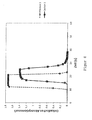
Die theoretischen Überlegungen gemäß der
- (a) eine Verzögerung der führenden Flanke des Bolus um 5sec, welche auf die Wegstrecke zwischen den Sensoren zurückzuführen ist. Ferner ergibt sich, dass
- (b) das dekadische Absorptionsmaß sein Plateau erst 8sec nach Start des Bolusses gegenüber 1
sec bei Sensor 1 erreicht. Quantitativ lässt sich feststellen, dass - (c) bei
Sensor 2 das Plateau des dekadischen Absorptionsmaßes 20% unterdem bei Sensor 1 liegt - dies führt zu einem entsprechenden Fehler bei der Bestimmung der Konzentration. Schließlich lässt sich - (d) eine fallende Flanke im
Signal von Sensor 2 von 7sec Länge identifizieren, im Vergleich zu derFlanke von 1 sec Länge des gleichen Bolus inSensor 1.
- (a) a delay of the leading edge of the bolus by 5 sec, which is due to the distance between the sensors. It also follows that
- (b) the absorbance reaches its plateau only 8 seconds after the start of the bolus compared to 1 sec at
sensor 1. Quantitatively, it can be stated that - (c) in
Sensor 2, the plateau of the absorbance decay is 20% lower than that of Sensor 1 - this leads to a corresponding error in the determination of the concentration. Finally, you can - (d) identify a falling edge in the signal from
sensor 2 of 7sec length, compared to the edge of 1 sec length of the same bolus insensor 1.
Aus
Als Beispiel hierfür soll die Genauigkeit der Konzentrationsbestimmung dienen, welche sich bei der Zeit t = 0,1 min aus
In der Dialyse ist der Ort der Entstehung einer Konzentrationsänderung oder eines Konzentrationspulses meist der Dialysator. Entsprechend besteht eine Lösung des beschriebenen Problems gemäß der Erfindung darin, die Messvorrichtung als eine Bedingung höchstens 250 cm, vorzugsweise weniger als 200 cm, vorzugsweise weniger als 150 cm, vorzugsweise weniger als 100 cm, vorzugsweise weniger als 50 cm, vorzugsweise weniger als 20 cm Schlauch- oder Kanallänge vom Abfluss der verbrauchten Dialysierflüssigkeit aus dem Dialysator zu platzieren.In dialysis, the place of origin of a change in concentration or a concentration pulse is usually the dialyzer. Accordingly, a solution of the described problem according to the invention is the measuring device as a condition at most 250 cm, preferably less than 200 cm, preferably less than 150 cm, preferably less than 100 cm, preferably less than 50 cm, preferably less than 20 cm Hose or channel length from the outflow of used dialysis fluid from the dialyzer to place.
Obige Rechnungen wurden durchgeführt unter der Annahme von Kanälen und/oder Schläuchen gleichbleibenden Durchmessers. In Dialysemaschinen ist dies jedoch nicht unbedingt gewährleistet. Aufgrund von Variationen im Kanal- oder Schlauchdurchmesser, verursacht z.B. von Koppelstücken, Ventilen und sonstigen fluidischen Elementen, und den damit verbundenen Änderungen in der Flussgeschwindigkeit bei konstantem Volumenfluss, kann der vorstehende Lösungsansatz analog auf Volumina zwischen Entstehungsstelle einer Konzentrationsänderung und Position der Messvorrichtung als eine zweite zusätzliche oder alternative Bedingung übertragen werden. Eine vorteilhafte Positionierung des Sensors sollte gemäß dieser zweiten Bedingung erfindungsgemäß kleiner gleich 150 ml (Leitungs- und Komponenten-Füllvolumen) vom Abfluss der verbrauchten Dialysierflüssigkeit aus dem Dialysator bis zum Sensor erfolgen, vorzugsweise kleiner gleich 100 ml, vorzugsweise kleiner gleich 50 ml, vorzugsweise kleiner gleich 35 ml, vorzugsweise kleiner gleich 20 ml bei einem (mittleren) Kanal-/Schlauchquerschnitt von vorzugsweise ca. 3-7mm (weiter vorzugsweise ca. 5mm) und unter Berücksichtigung der Dialysierflüssigkeitsvolumen der im Dialysierflüssigkeitspfad angebrachten Komponenten.The above calculations were made assuming channels and / or tubes of constant diameter. However, this is not necessarily guaranteed in dialysis machines. Due to variations in the channel or tube diameter, e.g. couplings, valves, and other fluidic elements, and the associated changes in flow rate at constant volume flow, the above approach can be analogously applied to volumes between the point of origin of concentration change and position of the measuring device as a second additional or alternative condition. According to this second condition, an advantageous positioning of the sensor according to the invention should be less than or equal to 150 ml (line and component filling volume) from the outflow of used dialysis fluid from the dialyzer to the sensor, preferably less than or equal to 100 ml, preferably less than or equal to 50 ml, preferably smaller equal to 35 ml, preferably less than or equal to 20 ml with a (mean) channel / tube cross-section of preferably about 3-7mm (more preferably about 5mm) and taking into account the dialysis fluid volume of the components mounted in the dialysis fluid pathway.
Auf der Grundlage der vorstehenden theoretischen und analytischen Betrachtungen wurde gefunden, dass eine Anordnung der Detektions-/Messvorrichtung (Sensor) am proximalen (d.h. Dialysator nahen) Abschnitt des Abflusses der Dialysierflüssigkeit aus der dialysierflüssigkeitsseitigen Kammer eines Filterelements unter Erfüllung zumindest einer der zwei Bedingungen das gestellte Problem löst und die zuvor beschriebenen Probleme im Stand der Technik überwindet.On the basis of the above theoretical and analytical considerations, it has been found that an arrangement of the detection / measuring device (sensor) at the proximal (ie dialyzer) portion of the outflow of the dialysis fluid from the dialysis fluid-side chamber of a filter element while fulfilling at least one of the two conditions solves the problem posed and overcomes the problems of the prior art described above.
Die erfindungsgemäße Vorrichtung zur extrakorporalen Blutbehandlung hat unter anderem vorzugsweise die folgenden Bauteile:
- ein Filterelement (Dialysator), das in eine blutseitige Kammer und in eine dialysierflüssigkeitsseitige Kammer geteilt ist mit einem Zufluss für eine frische Dialysierflüssigkeit zur dialysierflüssigkeitsseitigen Kammer und einem Abfluss für die verbrauchte Dialysierflüssigkeit aus der dialysierflüssigkeitsseitigen Kammer,
- eine dem Filterelement nachgeschaltete Bilanzierungseinrichtung,
- eine Detektions-/Messvorrichtung (Sensor), die geeignet ist, kontinuierlich oder getaktet die Konzentration mindestens eines Abbauprodukts aus dem Blut des Patienten dialysierflüssigkeitsseitig zu erfassen,
- ein Gehäuse, innerhalb welchem unter anderem zumindest die Bilanzierungseinrichtung und vorzugsweise die Detektions-/Messvorrichtung eingehaust sind und außerhalb welchem das Filterelement angeordnet ist sowie eine Fluidleitungsdurchführung durch das Gehäuse, über die das Filterelement mit der Bilanzierungseinrichtung fluidverbunden/fluidverbindbar ist, wobei
- die Detektions-/Messvorrichtung an der Fluidleitungsdurchführung (unmittelbar stromab zu dieser) vorzugsweise gehäuseintern angeordnet ist.
- a filter element (dialyzer) divided into a blood side chamber and a dialyzing fluid side chamber having a fresh dialyzing fluid inflow to the dialyzing fluid side chamber and an outflow for the used dialyzing fluid from the dialyzing fluid side chamber,
- a downstream of the filter element balancing device,
- a detection / measuring device (sensor) which is suitable for continuous or timed recording of the concentration of at least one degradation product from the blood of the patient on the dialysis fluid side,
- a housing within which, inter alia, at least the balancing device and preferably the detection / measuring device are housed and outside which the filter element is arranged and a fluid line passage through the housing, via which the filter element with the balancing device is fluidly connected / fluidverbindbar, wherein
- the detection / measuring device is arranged on the fluid line feedthrough (directly downstream of this), preferably inside the housing.
Dabei kann die erfindungsgemäße Vorrichtung zur extrakorporalen Blutbehandlung zudem weitere Bauteile umfassen, die aus dem Stand der Technik per se bekannt sind und zur Standardausstattung moderner Dialysemaschinen gehören oder gehören werden, wie beispielsweise eine Druckmessvorrichtung vorzugsweise in/an der Gehäusewand im Bereich der Fluidleitungsdurchführung und damit unmittelbar stormauf zur Detektions-/Messvorrichtung und/oder eine das Filterelement kurzschließende Bypassleitung vorzugsweise stromab zur Detektions-/Messvorrichtung oder alternativ stromauf zur Detektions-/Messvorrichtung, dann u.a. zum Zweck einer Kalibrierung der Detektions-/Messvorrichtung. Da diese weiteren Bauteile aber für die vorliegende Erfindung nur von sekundärer Bedeutung sind, werden diese der Übersichtlichkeit halber vorliegend nicht im Detail angeführt.The device according to the invention for extracorporeal blood treatment may also comprise other components which are known per se from the prior art and belong to the standard equipment of modern dialysis machines, such as a pressure measuring device preferably in / on the housing wall in the region of the fluid line feedthrough and thus directly stormauf to the detection / measuring device and / or a short-circuiting the filter element bypass line preferably downstream of the detection / measuring device or alternatively upstream to the detection / measuring device, then, inter alia, for the purpose of calibration of the detection / measuring device. Because these other components but for the The present invention are of secondary importance only, these are not given in detail for the sake of clarity present.
Die erfindungsgemäße Vorrichtung zur extrakorporalen Blutbehandlung kann dabei jedwede Geräte umfassen, die sich zur Dialyse eignen, insbesondere künstliche Nieren und Dialysemaschinen. Vorteilhaft an der Erfindung ist die Verbesserung der Messgenauigkeit und Schärfe des Messsignals zur Konzentrationsbestimmung von aus dem Blut zu reinigenden physiologischen Abfallprodukten. Die zuvor geschilderten Probleme bei der extrakorporalen Blutbehandlung werden somit gelöst und das Erkennen und Quantifizieren von Konzentrationsänderungen wird mit besonderer Genauigkeit ermöglicht.The device according to the invention for extracorporeal blood treatment may comprise any devices which are suitable for dialysis, in particular artificial kidneys and dialysis machines. An advantage of the invention is the improvement of the measurement accuracy and sharpness of the measurement signal for determining the concentration of physiological waste products to be purified from the blood. The above-described problems in the extracorporeal blood treatment are thus solved and the detection and quantification of changes in concentration is made possible with particular accuracy.
Weitere Merkmale und Vorteile der Erfindung ergeben sich aus der folgenden Beschreibung, bei der Bezug genommen wird auf die beigefügte Zeichnung.
-
Figur 1 -
Figur 2 -
Figur 3 -
Figur 4 zeigt einen Dialysierflüssigkeitskreislauf mit einer Vorrichtung zur extrakorporalen Blutbehandlung für eine Hämofiltration, -
Figur 5 -
Figur 6 zeigt, wie bereits beschrieben, den Verlauf der Konzentration über die Zeit bei verschiedenen Positionen der Messvorrichtung nach einer sprunghaften Konzentrationsänderung, -
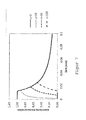
Figur 7 -
Figur 8 -
Figur 9 -
Figur 10
-
FIG. 1 shows a dialysis fluid circuit with a device for extracorporeal blood treatment for hemodyysis, -
FIG. 2 shows a dialysis fluid circuit with an apparatus for extracorporeal blood treatment for hemodiafiltration, -
FIG. 3 shows a dialysis fluid circuit with a device for extracorporeal blood treatment for the withdrawal of fluid during a seqiuentiellen therapy -
FIG. 4 shows a dialysis fluid circuit with a device for extracorporeal blood treatment for hemofiltration, -
FIG. 5 shows, as already described, the response of a UV measuring device at a position according to the prior art, -
FIG. 6 shows, as already described, the course of the concentration over time at different positions of the measuring device after a sudden change in concentration, -
FIG. 7 shows, as already described, the response of a UV measuring device as a function of its positioning to a concentration pulse in the device according to the invention, -
FIG. 8 shows, as already described, the UV absorbance after a bolus, as detected by a first and a second sensor, -
FIG. 9 shows the measurement result of a dialysis machine with a UV measuring device in a conventional position and -
FIG. 10 shows a comparison of the reaction delay to a concentration pulse of uric acid in a dialysis machine with a UV measuring device at a conventional position and in a proximal (dialyzer near) section of the outflow of dialysis fluid.
Die Figuren sind rein illustrativ und daher nicht maßstäblich. Gleiche oder gleich wirkende Elemente sind mit denselben Bezugszeichen versehen, soweit nichts anderes gesagt ist.The figures are purely illustrative and therefore not to scale. Identical or equivalent elements are provided with the same reference numerals, unless otherwise stated.
Erfindungsgemäß befindet sich eine Detektions-/Messvorrichtung 14 nahe am Filterelement (Dialysator), d.h. zwischen dem Ausgang des Filterelements und der Bypass - Leitung 11, vorzugsweise zwischen dem Filterelementausgang und dem zweiten Ventil 10. Ergänzend oder alternativ befindet sich eine Detektions-/Messvorrichtung 14a stomab zu der Bypass - Leitung 11.According to the invention, a detection / measuring
An dieser Stelle sei darauf hingewiesen, dass bei der vorliegenden Vorrichtung zur extrakorporalen Blutbehandlung das Filterelement außerhalb eines in der
In der Regel werden Leitungen (Schläuche) mit einem Leitungsinnenquerschnitt von ca. 3 - 7 mm, vorzugsweise 5 mm verwendet. Die Leitungslänge zwischen dem Filterelementausgang und der Detektionsvorrichtung 14 oder 14a beträgt erfindungsgemäß höchstens 250 cm, vorzugsweise weniger als 200 cm, vorzugsweise weniger als 150 cm, vorzugsweise weniger als 100 cm, vorzugsweise weniger als 50 cm und weiter vorzugsweise weniger als 20 cm Schlauch- oder Kanallänge. Alternativ oder zusätzlich hierzu ist eine vorteilhafte Positionierung der Detektionsvorrichtung 14 oder 14a (d.h. des Sensors) dann gegeben, wenn das Schlauch-/Leitungsvolumen zwischen dem Filterelementausgang und der Detektionsvorrichtung 14 oder 14a kleiner gleich 100 ml, vorzugsweise kleiner gleich 50 ml, vorzugsweise kleiner gleich 35 ml, vorzugsweise kleiner gleich 30 ml, vorzugsweise kleiner gleich 15 ml und weiter vorzugsweise kleiner gleich 7 ml beträgt, ebenfalls jeweils vorzugsweise bei einem Strömungsquerschnitt von ca. 3 - 7 mm (ca. 5 mm). Dabei sei darauf hingewiesen, dass in Abhängigkeit vom Modell der Dialysemaschine bei einer Schlauchlänge von weniger als 100 cm bzw. bei einem Volumen von weniger als 20-30 ml eine Positionierung des Sensors außerhalb des Maschinengehäuses erfolgt, sodass die Einhausung des Sensors erstrebenswert aber nicht grundsätzlich immer verwirklichbar ist.As a rule, lines (hoses) are used with an internal pipe section of about 3 - 7 mm, preferably 5 mm. The line length between the filter element outlet and the
Mittels einer Flussmesseinrichtung 16 zwischen dem ersten Ventil 8 und dem Filterelement wird optional der im Kreislauf umgewälzte Fluidvolumenstrom bestimmt/gemessen.By means of a
Der Patient ist über ein arterielles Schlauchsystem 17 mit der Vorrichtung zur extrakorporalen Blutbehandlung (Dialysemaschine) verbindbar. Eine arterielle Blutpumpe (BPA) 18 ist dafür vorgesehen oder angepasst, dem Patienten ungereinigtes Blut zu entziehen und es einer Blutseite (BS) 19 im Filterelement zuzuführen, die mit einer Dialysierflüssigkeitsseite (DS) 20 im Filterelement über eine semipermeable Membran in Verbindung steht. Aus der Blutseite (BS) 19 im Filterelement kann dann gereinigtes Blut über ein venöses Schlauchsystem 21 wieder dem Patienten zugeführt werden.The patient is connected via an
Gesteuert wird der Kreislauf und die Komponenten für die dialysierflüssigkeitsseitige, wie auch die blutseitige Fluidumwälzung durch eine Recheneinheit 30, die mit einem User-Interface 31 versehen ist.The circulation and the components for the dialysis fluid-side as well as the blood-side fluid circulation are controlled by a
Wie bei der Ausführungsform nach
In
Die Erfindung ist nicht auf die oben beschriebenen Ausführungsformen beschränkt. Im Sinne der vorliegenden Erfindung ist vielmehr unter der die Bedingungen erfüllenden Stelle konstruktiv häufig derjenige Bereich des Abflusses der Dialysierflüssigkeit aus der dialysierflüssigkeitsseitigen Kammer des Filterelements zu verstehen, der sich unmittelbar an den Ausflussstutzen der dialysierflüssigkeitsseitigen Kammer des Filterelements anschließt jedoch bevorzugt noch innerhalb des Vorrichtungsgehäuses liegt.The invention is not limited to the embodiments described above. For the purposes of the present invention, the site fulfilling the conditions is rather constructively often understood to be that region of the outflow of the dialysis fluid from the dialyzing fluid-side chamber of the filter element, which immediately adjoins the outflow port of the dialysis fluid-side chamber of the filter element, but preferably still lies within the device housing.
Dieser Leitungsabschnitt kann sich somit je nach Dimensionierung der Blutbehandlungsvorrichtung sowie Platzierung des Filterelements maximal vom Ausflussstutzen der dialysierflüssigkeitsseitigen Kammer des Filterelements bis zum Einlass in die Bilanzierungseinrichtung erstrecken. Der Abschnitt kann ferner eine Spülbrücke umfassen. Die Detektionsvorrichtung kann sich bei einem solchen Aufbau stromauf oder stromab zu der Spülbrücke befinden; sie ist jedoch erfindungsgemäß in jedem Fall vor der Bilanzierungseinrichtung angeordnet, um eine Verfälschung und Verschlechterung des Signals verursacht durch die Bilanzierungseinrichtung zu verhindern. Obgleich die Detektionsvorrichtung bevorzugt innerhalb des Vorrichtungsgehäuses angeordnet ist, um diese gegen äußere Kräfte zu schützen, kann diese auch extern d.h. außerhalb des Gehäuses an die Vorrichtung zur extrakorporalen Blutbehandlung angebracht sein, insbesondere dann, wenn nur dadurch die vorstehend genannten Bedingungen bezgl. Leitungslänge und/oder Leitungsfüllvolumen erfüllbar sind. Unter dem Begriff "bis zur Detektionsvorrichtung" wird ferner die Stelle bezeichnet, wo in oder an der Detektionsvorrichtung die Messung vorgenommen wird. Dies ist vorzugsweise die Stelle, wo beispielsweise im Fall eines UV-Sensors der optische Messstrahl die Dialysierflüssigkeit durchquert.Depending on the dimensions of the blood treatment device and the placement of the filter element, this line section can thus extend as far as possible from the outlet connection of the dialysis fluid-side chamber of the filter element to the inlet into the balancing device. The section may further include a rinse bridge. The detection device may be in such a structure upstream or downstream of the scavenging bridge; However, it is arranged according to the invention in any case in front of the balancing device in order to prevent corruption and deterioration of the signal caused by the balancing device. Although the detection device is preferably arranged inside the device housing in order to protect it against external forces, it can also be mounted externally, ie outside the housing, on the device for extracorporeal blood treatment, in particular if only as a result the aforementioned conditions regarding cable length and / or or line filling volume can be fulfilled. The term "to the detection device" also refers to the point where the measurement is made in or on the detection device. This is preferably the point where, for example, in the case of a UV sensor, the optical measuring beam traverses the dialysis fluid.
Bevorzugt umfasst der Leitungsabschnitt zwischen Filterelement und Detektionsvorrichtung gemäß der obigen Festlegung maximal den Bereich vom Ausfluss des Filterelements bis zur Bilanzierungseinrichtung. Bevorzugt ist ein Bereich von 250 cm (Leitungslänge) in Flussrichtung von dem Auslass oder Abfluss des Filterelements in Richtung Bilanzierungseinrichtung , weiter bevorzugt 200 cm, noch weiter bevorzugt 150 cm, noch weiter bevorzugt 100 cm, noch weiter bevorzugt 90 cm, noch weiter bevorzugt 80 cm, noch weiter bevorzugt 70 cm, noch weiter bevorzugt 60 cm, noch weiter bevorzugt 50 cm, noch weiter bevorzugt 40 cm, noch weiter bevorzugt 30 cm, noch weiter bevorzugt 20 cm und am meisten bevorzugt 10 cm von dem Auslass oder Abfluss des Filterelements in Richtung Bilanzierungseinrichtung.Preferably, the line section between the filter element and the detection device according to the above definition comprises at most the area from the outflow of the filter element to the balancing device. A range of 250 cm (line length) in the flow direction from the outlet or outflow of the filter element in the direction of the balancing device is preferred, more preferably 200 cm, even more preferably 150 cm, even more preferably 100 cm, even more preferably 90 cm, even more preferably 80 cm, more preferably 70 cm, even more preferably 60 cm, even more preferably 50 cm, even more preferably 40 cm, even more preferably 30 cm, even more preferably 20 cm and most preferably 10 cm from the outlet or outflow of the filter element towards the accounting facility.
Weiter bevorzugt bezieht sich diese Anmeldung auf eine Vorrichtung zur extrakorporalen Blutbehandlung, bei der die Detektionsvorrichtung eine UV-Messvorrichtung ist. Diese umfasst zumindest eine Strahlungsquelle und zumindest einen Sensor. Als Strahlungsquellen kommen UV-LEDs, UV-Laser und breitbandige Strahlungsquellen wie z.B. Deuteriumlampen in Frage. Die Sensoren werden aus der Gruppe bestehend aus Photodioden, Phototransistoren, CCD- und CMOS-Detektoren, Photomultiplier oder Photon-Counting Modulen oder Elementen vergleichbarer Funktion ausgesucht. Ebenfalls ist bevorzugt, wenn der Sensor der UV-Messvorrichtung mindestens im Wellenlängenbereich von 200 bis 350 nm arbeitet. Dieser Wellenlängenbereich ist von besonderem Interesse, da in diesem Wellenlängenbereich viele für die Exkretion bedeutsame Metaboliten bzw. physiologische Abfallprodukte einen charakteristischen Absorptionspeak aufweisen, beispielsweise Harnsäure bei 290 nm, Kreatinin bei ca. 235 nm. Hippursäure bei ca. 260 nm und Kreatin bei ca. 210 nm. Aus einem solchen charakteristischen Absorptionspeak oder aus einer kombinatorischen Analyse mehrerer dieser Peaks lässt sich verlässlich auf die jeweilige Konzentration des Metaboliten zurückschließen.More preferably, this application relates to a device for extracorporeal blood treatment, in which the detection device is a UV measuring device. This comprises at least one radiation source and at least one sensor. The sources of radiation are UV LEDs, UV lasers and broadband radiation sources, e.g. Deuterium lamps in question. The sensors are selected from the group consisting of photodiodes, phototransistors, CCD and CMOS detectors, photomultipliers or photon counting modules or elements of comparable function. It is likewise preferred if the sensor of the UV measuring device operates at least in the wavelength range from 200 to 350 nm. This wavelength range is of particular interest, since in this wavelength range many metabolites or physiological waste products important for the excretion have a characteristic absorption peak, for example uric acid at 290 nm, creatinine at about 235 nm, hippuric acid at about 260 nm and creatine at ca. 210 nm. From such a characteristic absorption peak or from a combinatorial analysis of several of these peaks, one can reliably deduce the respective concentration of the metabolite.
Im folgenden werden drei Beispiele angegeben, in denen der Unterschied zwischen dem Stand der Technik und der Erfindung deutlich wird. Dabei wird Bezug genommen auf das Messergebnis nach
In einem ersten Beispiel aus dem Stand der Technik wird in einer Dialysemaschine mit einer UV-Messvorrichtung an einer herkömmlichen Position zum Zeitpunkt "1" am Dialysator die Konzentration von Harnsäure in herkömmlicher Dialysierflüssigkeit von null auf einen konstanten Wert (83,4 mg/l) erhöht, indem zum Zeitpunkt "1" die Maschine bei laufender Blutpumpe aus dem Bypass genommen wird. Der Fluss der Dialysierflüssigkeit beträgt konstant 500 ml/min, dies entspricht einer realistischen Flussgeschwindigkeit der Dialysierflüssigkeit bei einer Hämodialyse. Die Temperatur der Dialysierflüssigkeit am Punkt der UV-Messvorrichtung beträgt ca. 35 °C. Auch dies entspricht den üblichen Bedingungen einer Hämodialyse. Erst 30 - 40 Sekunden später treffen erste Harnsäuremoleküle am Sensor ein, d.h. zum Zeitpunkt "2". Bis sich das Signal vollständig entwickelt hat, vergehen mehr als 5 Minuten seit der Zugabe der Harnsäure, d.h. bis zum Zeitpunkt "3". Aus
In einem zweiten Beispiel aus dem Stand der Technik wird in einer Dialysemaschine mit einer UV-Messvorrichtung an einer herkömmlicher Position ein zeitlich klar umrissener Konzentrationspuls von 45sec Länge appliziert, der in
In einem dritten Beispiel wird die Reaktionsverzögerung auf einen Konzentrationspuls von Harnsäure in einer Dialysemaschine mit einer UV-Messvorrichtung an einer herkömmlichen Position (im zentralen Abschnitt des Abflusses der Dialysierflüssigkeit der Bilanzierungseinrichtung in Strömungsrichtung nachgelagert) mit derjenigen mit einer UV-Messvorrichtung im proximalen Abschnitt des Abflusses der Dialysierflüssigkeit verglichen. Der Verlauf beider Kurven ist in
Die Erfindung bezieht sich zusammenfassend auf eine Vorrichtung zur extrakorporalen Blutbehandlung, mit einer Detektionsvorrichtung (14, 14a) zur Erfassung urämischer Toxine in einer verbrauchten Dialysierflüssigkeit vorzugsweise durch Absorbanzmessung, wobei die Detektionsvorrichtung (14, 14a) an einer solchen Position stromab zum Abflusses (13) der Dialysierflüssigkeit aus einem Filterelement angebracht ist, die zumindest eine der folgenden Bedingungen erfüllt:
- a) das Fluidleitungs-/Komponenten - Füllvolumen ausgehend vom Abfluss der verbrauchten Dialysierflüssigkeit aus dem Filterelement bis zur Detektionsvorrichtung (14, 14a) ist kleiner gleich 100 ml, vorzugsweise kleiner gleich 50 ml, vorzugsweise kleiner gleich 35 ml, vorzugsweise kleiner gleich 30 ml, vorzugsweise kleiner gleich 15 ml, vorzugsweise kleiner gleich 7 ml und
- b) die Fluidleitungslänge ausgehend vom Abfluss der verbrauchten Dialysierflüssigkeit aus dem Filterelement bis zur Detektionsvorrichtung (14, 14a) ist höchstens 250 cm, vorzugsweise kleiner gleich 200 cm, vorzugsweise kleiner gleich 150 cm, vorzugsweise kleiner gleich 100 cm, vorzugsweise kleiner gleich 50 cm, vorzugsweise kleiner gleich 20 cm.
- a) the fluid line / component filling volume starting from the outflow of the used dialyzing fluid from the filter element to the detection device (14, 14a) is less than or equal to 100 ml, preferably less than or equal to 50 ml, preferably less than or equal to 35 ml, preferably less than or equal to 30 ml, preferably less than or equal to 15 ml, preferably less than or equal to 7 ml
- b) the fluid line length starting from the outflow of used dialysis fluid from the filter element to the detection device (14, 14a) is at most 250 cm, preferably less than or equal to 200 cm, preferably less than or equal to 150 cm, preferably less than or equal to 100 cm, preferably less than or equal to 50 cm, preferably less than or equal to 20 cm.
- 11
- Dialysierflüssigkeitsquelledialysis fluid
- 22
- DlalysierflüssigkeitszuflussDlalysierflüssigkeitszufluss
- 77
- Flusspumpe-Filterelement-Eingang (FPE)Flow Pump Filter Element Inlet (FPE)
- 88th
- Ventil Filterelement Eingang (VDE)Valve Filter Element Inlet (VDE)
- 99
- Bypass-Ventil (VBP)Bypass valve (VBP)
- 1010
- Ventil Filterelement Ausgang (VDA)Valve Filter Element Output (VDA)
- 1111
- Bypass-LeitungBypass line
- 1212
- Flusspumpe DialysierflüssigkeitsausgangFlow pump dialysis fluid outlet
- 1313
- DialysierflüssigkeitsabflussleitungDialysierflüssigkeitsabflussleitung
- 1414
- Detektionsvorrichtungdetection device
- 14a14a
- Alternativposition DetektionsvorrichtungAlternative position detection device
- 1515
- DialysierflüssigkeitsabflussDialysierflüssigkeitsabfluss
- 1616
- FlussmesseinrichtungFlow meter
- 1717
- arterielles Schlauchsystemarterial tube system
- 1818
- arterielle Blutpumpe (BPA)arterial blood pump (BPA)
- 1919
- Blutseite (BS) im FilterelementBlood side (BS) in the filter element
- 2020
- Dialysierflüssigkeitsseite (DS) im FilterelementDialysis fluid side (DS) in the filter element
- 2121
- venöses Schlauchsystemvenous tube system
- 2222
- SubstitutionsflüssigkeitsquelleSubstitution fluid source
- 2323
- Substitutionspumpesubstitution pump
- 3030
- Recheneinheitcomputer unit
- 3131
- User InterfaceUser interface
Claims (9)
die Detektionsvorrichtung (14, 14a) an einer Position stromab zum Abflusses (13) der Dialysierflüssigkeit aus der dialysierflüssigkeitsseitigen Kammer (20) des Filterelements angebracht ist, die zumindest eine der folgenden Bedingungen erfüllt:
the detection device (14, 14a) is mounted at a position downstream of the outflow (13) of the dialysis fluid from the dialysis fluid-side chamber (20) of the filter element, which fulfills at least one of the following conditions:
Applications Claiming Priority (1)
| Application Number | Priority Date | Filing Date | Title |
|---|---|---|---|
| DE102013104501.4A DE102013104501A1 (en) | 2013-05-02 | 2013-05-02 | Device for extracorporeal blood treatment |
Publications (3)
| Publication Number | Publication Date |
|---|---|
| EP2799097A2 true EP2799097A2 (en) | 2014-11-05 |
| EP2799097A3 EP2799097A3 (en) | 2015-06-03 |
| EP2799097B1 EP2799097B1 (en) | 2018-03-28 |
Family
ID=50486848
Family Applications (1)
| Application Number | Title | Priority Date | Filing Date |
|---|---|---|---|
| EP14165194.3A Active EP2799097B1 (en) | 2013-05-02 | 2014-04-17 | Device for treating blood outside the body |
Country Status (4)
| Country | Link |
|---|---|
| US (1) | US9700662B2 (en) |
| EP (1) | EP2799097B1 (en) |
| CN (2) | CN104127928B (en) |
| DE (1) | DE102013104501A1 (en) |
Families Citing this family (17)
| Publication number | Priority date | Publication date | Assignee | Title |
|---|---|---|---|---|
| DE102013104501A1 (en) * | 2013-05-02 | 2014-11-06 | B. Braun Avitum Ag | Device for extracorporeal blood treatment |
| EP3302606B1 (en) * | 2015-05-25 | 2021-06-16 | Gambro Lundia AB | Apparatus for extracorporeal blood treatment ii |
| CN107666918B (en) | 2015-05-25 | 2021-01-15 | 甘布罗伦迪亚股份公司 | Device for extracorporeal blood treatment |
| US10646632B2 (en) | 2015-05-25 | 2020-05-12 | Gambro Lundia Ab | Apparatus for extracorporeal blood treatment |
| US10406269B2 (en) | 2015-12-29 | 2019-09-10 | Fresenius Medical Care Holdings, Inc. | Electrical sensor for fluids |
| US10617809B2 (en) | 2015-12-29 | 2020-04-14 | Fresenius Medical Care Holdings, Inc. | Electrical sensor for fluids |
| DE102016007828A1 (en) * | 2016-06-29 | 2018-01-04 | Fresenius Medical Care Deutschland Gmbh | Blood detection control unit in a dialysis fluid discharge line of a blood treatment device and blood treatment device |
| DE102017102175A1 (en) * | 2017-02-03 | 2018-08-09 | B. Braun Avitum Ag | Air separator with forced circulation |
| DE102017110269A1 (en) * | 2017-05-11 | 2018-11-15 | B. Braun Avitum Ag | Online linearization of an optical sensor |
| DE102017116097A1 (en) * | 2017-07-18 | 2019-01-24 | B. Braun Avitum Ag | Apparatus and method for performing isonatremic dialysis |
| EP3431119B1 (en) | 2017-07-19 | 2022-11-16 | Gambro Lundia AB | Apparatus for extracorporeal treatment of blood |
| CN107741404A (en) * | 2017-11-02 | 2018-02-27 | 重庆山外山血液净化技术股份有限公司 | A kind of blood purification system urea content monitoring device |
| CN114728159A (en) | 2019-11-12 | 2022-07-08 | 费森尤斯医疗护理德国有限责任公司 | Blood treatment system |
| EP4058094A1 (en) | 2019-11-12 | 2022-09-21 | Fresenius Medical Care Deutschland GmbH | Blood treatment systems |
| CN114746129A (en) | 2019-11-12 | 2022-07-12 | 费森尤斯医疗护理德国有限责任公司 | Blood treatment system |
| WO2021094144A1 (en) | 2019-11-12 | 2021-05-20 | Fresenius Medical Care Deutschland Gmbh | Blood treatment systems |
| US20230414849A1 (en) * | 2022-06-22 | 2023-12-28 | B. Braun Medical Inc. | Fluid handling systems and methods |
Citations (6)
| Publication number | Priority date | Publication date | Assignee | Title |
|---|---|---|---|---|
| WO2000002000A1 (en) | 1998-07-03 | 2000-01-13 | Alkan | Passive fail-safe device for mobile craft such as a helicopter |
| EP1342479A1 (en) | 2002-03-08 | 2003-09-10 | BELLCO S.p.A. | Assembly for controlling and regulating flow of a dialysis solution in a haemodiafiltration process |
| EP1083948B1 (en) | 1998-06-04 | 2004-03-31 | Althin Medical Ab | Method for determining waste products in the dialysis liquid in dialysis treatment |
| US20110144459A1 (en) | 2009-12-14 | 2011-06-16 | Nikkiso Co., Ltd. | Liquid concentration detector for a blood purification apparatus |
| EP2397167A1 (en) | 2010-06-16 | 2011-12-21 | B. Braun Avitum AG | Device for treating blood outside the body comprising a measurement device for the determination of a luminescence of the spent dialysate |
| DE102011008482A1 (en) | 2010-03-09 | 2012-01-19 | Ldiamon As | UV-detector arrangement for use in photometric UV sensor in drain outlet of dialysis arrangement utilized for kidney replacement therapy of patient, has wide-band and narrow-band photo detectors arranged adjacent to portion of wall |
Family Cites Families (29)
| Publication number | Priority date | Publication date | Assignee | Title |
|---|---|---|---|---|
| US4083777A (en) * | 1976-09-07 | 1978-04-11 | Union Carbide Corporation | Portable hemodialysis system |
| US5849179A (en) * | 1992-10-13 | 1998-12-15 | Baxter International Inc. | Automatic apparatus for obtaining equilibration samples of dialysate |
| MX9306336A (en) * | 1992-10-13 | 1995-01-31 | Baxter Int | METHOD AND APPARATUS FOR MONITORING OR MONITORING A HEMODIALYSIS TREATMENT, WHICH IS CARRIED OUT IN A HEMODIALISIS MACHINE. |
| US5368555A (en) * | 1992-12-29 | 1994-11-29 | Hepatix, Inc. | Organ support system |
| CN1073449C (en) * | 1993-03-17 | 2001-10-24 | 信东化学工业股份有限公司 | Instant proper dialysis device and method |
| US5403746A (en) * | 1993-11-30 | 1995-04-04 | Minnesota Mining And Manufacturing Company | Sensor with improved drift stability |
| SE9702074D0 (en) * | 1997-06-02 | 1997-06-02 | Gambro Ab | Method and device for calculating dialysis efficiency |
| SE513034C2 (en) * | 1997-06-02 | 2000-06-19 | Gambro Lundia Ab | Calculation of dialysis efficiency, especially by monitoring urea concentration |
| ES2441254T3 (en) * | 1997-08-13 | 2014-02-03 | Fresenius Medical Care Deutschland Gmbh | Method to determine hemodialysis parameters and blood treatment equipment with equipment to determine hemodialysis parameters |
| SE9802333D0 (en) | 1998-06-29 | 1998-06-29 | Astra Pharma Prod | Novel combination |
| US7077819B1 (en) | 1998-12-24 | 2006-07-18 | Fresenius Medical Care Deutschland Gmbh | Method for determining the distribution volume of a blood component during an extracorporeal blood treatment and device for carrying out the method |
| FR2801794B1 (en) * | 1999-12-02 | 2002-01-11 | Hospal Ag | METHOD FOR DETERMINING A SIGNIFICANT PARAMETER OF THE PROGRESS OF AN EXTRACORPOREAL BLOOD TREATMENT |
| DE10038835B4 (en) | 2000-08-04 | 2005-07-07 | Roche Diagnostics Gmbh | Microdialysis system |
| DE10114283C2 (en) * | 2000-12-22 | 2003-04-24 | Fresenius Medical Care De Gmbh | Method for determining the ion concentration of the blood of a patient in citrate-anticoagulated hemodialysis and / or hemofiltration; dialysis machine |
| DE10317024A1 (en) * | 2003-04-11 | 2004-11-11 | Fresenius Medical Care Deutschland Gmbh | Blood treatment device |
| ATE477824T1 (en) * | 2007-06-20 | 2010-09-15 | Braun B Avitum Ag | DEVICE FOR DETERMINING THE REDUCTION RATIO OR THE KT/V RATIO OF A KIDNEY REPLACEMENT TREATMENT |
| AT505690B1 (en) * | 2007-08-31 | 2012-09-15 | Zentrum Fuer Biomedizinische Technologie Der Donau Uni Krems | METHOD OF DETERMINING ION CONCENTRATION IN CITRATE ANTICOAGULATED EXTRACORPORAL BLOOD CLEANING |
| DE102009036044A1 (en) * | 2009-08-04 | 2011-02-10 | Fresenius Medical Care Deutschland Gmbh | Device and method for detecting blood or blood components in the fluid system of an apparatus for extracorporeal blood treatment |
| DE102010032154A1 (en) * | 2010-07-23 | 2012-01-26 | Fresenius Medical Care Deutschland Gmbh | Device for monitoring connection of blood treatment unit to liquid system of extracorporeal blood treatment device, has mediums for measuring pressure in one line section or another line section of line system |
| CN102946919B (en) * | 2010-06-11 | 2015-04-15 | 贝朗爱敦股份公司 | Apparatus for extracorporeal blood treatment, comprising a measuring device for determining the luminescence of the spent dialysate |
| DE102010023486A1 (en) * | 2010-06-11 | 2011-12-15 | B. Braun Avitum Ag | Detection device and method |
| DE102010034626A1 (en) * | 2010-08-17 | 2012-02-23 | B. Braun Avitum Ag | Device for extracorporeal blood treatment |
| US20120217027A1 (en) * | 2011-02-24 | 2012-08-30 | Kidde Technologies, Inc. | Extended discharge of odorant |
| DE102012109858A1 (en) * | 2012-10-16 | 2014-04-17 | B. Braun Avitum Ag | Dialysis optimization methods |
| US11565029B2 (en) * | 2013-01-09 | 2023-01-31 | Medtronic, Inc. | Sorbent cartridge with electrodes |
| US10010663B2 (en) * | 2013-02-01 | 2018-07-03 | Medtronic, Inc. | Fluid circuit for delivery of renal replacement therapies |
| DE102013103222A1 (en) * | 2013-03-28 | 2014-10-02 | B. Braun Avitum Ag | Recirculation detection by bolus administration |
| DE102013103221A1 (en) * | 2013-03-28 | 2014-10-02 | B. Braun Avitum Ag | Method for detecting recirculation in an arteriovenous shunt during ongoing hemodialysis and dialysis |
| DE102013104501A1 (en) * | 2013-05-02 | 2014-11-06 | B. Braun Avitum Ag | Device for extracorporeal blood treatment |
-
2013
- 2013-05-02 DE DE102013104501.4A patent/DE102013104501A1/en not_active Withdrawn
-
2014
- 2014-04-17 EP EP14165194.3A patent/EP2799097B1/en active Active
- 2014-04-29 US US14/264,867 patent/US9700662B2/en active Active
- 2014-05-04 CN CN201410184556.0A patent/CN104127928B/en active Active
- 2014-05-04 CN CN201420224941.9U patent/CN204147333U/en active Active
Patent Citations (6)
| Publication number | Priority date | Publication date | Assignee | Title |
|---|---|---|---|---|
| EP1083948B1 (en) | 1998-06-04 | 2004-03-31 | Althin Medical Ab | Method for determining waste products in the dialysis liquid in dialysis treatment |
| WO2000002000A1 (en) | 1998-07-03 | 2000-01-13 | Alkan | Passive fail-safe device for mobile craft such as a helicopter |
| EP1342479A1 (en) | 2002-03-08 | 2003-09-10 | BELLCO S.p.A. | Assembly for controlling and regulating flow of a dialysis solution in a haemodiafiltration process |
| US20110144459A1 (en) | 2009-12-14 | 2011-06-16 | Nikkiso Co., Ltd. | Liquid concentration detector for a blood purification apparatus |
| DE102011008482A1 (en) | 2010-03-09 | 2012-01-19 | Ldiamon As | UV-detector arrangement for use in photometric UV sensor in drain outlet of dialysis arrangement utilized for kidney replacement therapy of patient, has wide-band and narrow-band photo detectors arranged adjacent to portion of wall |
| EP2397167A1 (en) | 2010-06-16 | 2011-12-21 | B. Braun Avitum AG | Device for treating blood outside the body comprising a measurement device for the determination of a luminescence of the spent dialysate |
Non-Patent Citations (3)
| Title |
|---|
| "Haemodialysis Treatment monitored on-line by ultra violet absorbance", LINKÖPING UNIVERSITY MEDICAL DISSERTATION NO 962, 2006 |
| B. J. KIRBY: "Micro- and Nanoscale Fluid Mechanics", 2010, CAMBRIDGE UNIVERSITY PRESS |
| CALIA D.; DI FRANCESCO F.; FUOCO R.; GHIMENTI S.; KANAKI A.; ONOR M.; TOGNOTTI D.; DONADIO C.: "Monitoring Urea, Creatinine and ?2-Microglobulin Concentrations in Spent Dialysate by Spectrophotometric and Spectrofluorimetric Measurements", 52ND NATIONAL CONGRESS OF THE ITALIAN SOCIETY OF NEPHROLOGY, 21 September 2011 (2011-09-21) |
Also Published As
| Publication number | Publication date |
|---|---|
| EP2799097B1 (en) | 2018-03-28 |
| US20140326646A1 (en) | 2014-11-06 |
| CN104127928A (en) | 2014-11-05 |
| US9700662B2 (en) | 2017-07-11 |
| DE102013104501A1 (en) | 2014-11-06 |
| CN104127928B (en) | 2018-09-14 |
| CN204147333U (en) | 2015-02-11 |
| EP2799097A3 (en) | 2015-06-03 |
Similar Documents
| Publication | Publication Date | Title |
|---|---|---|
| EP2799097B1 (en) | Device for treating blood outside the body | |
| EP2714128B1 (en) | Device and method for recognizing an operating state of an extra-corporeal blood treatment | |
| EP1927370B1 (en) | Method for setting parameters for hemodialysis and blood processing device with a device for setting parameters for hemodialysis | |
| DE19747360B4 (en) | Method for measuring performance parameters of mass and energy exchange modules | |
| EP1615680B1 (en) | Haemodialysis device | |
| EP2722064B1 (en) | Dialysis optimisation method | |
| EP0711569B1 (en) | Means for determining the level of removed ureminatoxins during a dialysis treatment | |
| DE19746367C2 (en) | Method for in-vivo determination of parameters of hemodialysis and device for carrying out the method | |
| EP2942614B1 (en) | Device and device control method for quantitatively determining the concentration of selected substances in a liquid filtered out of a patient's body | |
| EP3431118B1 (en) | Device for providing isonatraemic dialysis | |
| EP1491222B1 (en) | Device for extracorporal blood treatment with equipment for checking a sterile filter and associated method | |
| EP2203198A1 (en) | Method and apparatus for monitoring the supply of replacement fluid during an extracorporeal treatment of blood | |
| DE102010034626A1 (en) | Device for extracorporeal blood treatment | |
| EP3174571B1 (en) | Device for identifying the direction of liquid flow through a dialyser | |
| DE102013103221A1 (en) | Method for detecting recirculation in an arteriovenous shunt during ongoing hemodialysis and dialysis | |
| DE102011119824A1 (en) | Method and device for determining a blood component | |
| EP2783713B1 (en) | Recirculation detection by bolus administration | |
| EP3955988B1 (en) | Recirculation measurement by means of diffusion equilibrium | |
| EP2461845B1 (en) | Device for extracorporeal blood treatment | |
| EP3400977B1 (en) | Online linearization of an optical sensor | |
| DE102016009442A1 (en) | Method for monitoring the bicarbonate content and the sodium content of a dialysis solution |
Legal Events
| Date | Code | Title | Description |
|---|---|---|---|
| PUAI | Public reference made under article 153(3) epc to a published international application that has entered the european phase |
Free format text: ORIGINAL CODE: 0009012 |
|
| 17P | Request for examination filed |
Effective date: 20140417 |
|
| AK | Designated contracting states |
Kind code of ref document: A2 Designated state(s): AL AT BE BG CH CY CZ DE DK EE ES FI FR GB GR HR HU IE IS IT LI LT LU LV MC MK MT NL NO PL PT RO RS SE SI SK SM TR |
|
| AX | Request for extension of the european patent |
Extension state: BA ME |
|
| PUAL | Search report despatched |
Free format text: ORIGINAL CODE: 0009013 |
|
| AK | Designated contracting states |
Kind code of ref document: A3 Designated state(s): AL AT BE BG CH CY CZ DE DK EE ES FI FR GB GR HR HU IE IS IT LI LT LU LV MC MK MT NL NO PL PT RO RS SE SI SK SM TR |
|
| AX | Request for extension of the european patent |
Extension state: BA ME |
|
| RIC1 | Information provided on ipc code assigned before grant |
Ipc: A61M 1/16 20060101AFI20150424BHEP |
|
| R17P | Request for examination filed (corrected) |
Effective date: 20151120 |
|
| RBV | Designated contracting states (corrected) |
Designated state(s): AL AT BE BG CH CY CZ DE DK EE ES FI FR GB GR HR HU IE IS IT LI LT LU LV MC MK MT NL NO PL PT RO RS SE SI SK SM TR |
|
| 17Q | First examination report despatched |
Effective date: 20160223 |
|
| GRAP | Despatch of communication of intention to grant a patent |
Free format text: ORIGINAL CODE: EPIDOSNIGR1 |
|
| INTG | Intention to grant announced |
Effective date: 20171005 |
|
| GRAS | Grant fee paid |
Free format text: ORIGINAL CODE: EPIDOSNIGR3 |
|
| GRAA | (expected) grant |
Free format text: ORIGINAL CODE: 0009210 |
|
| AK | Designated contracting states |
Kind code of ref document: B1 Designated state(s): AL AT BE BG CH CY CZ DE DK EE ES FI FR GB GR HR HU IE IS IT LI LT LU LV MC MK MT NL NO PL PT RO RS SE SI SK SM TR |
|
| REG | Reference to a national code |
Ref country code: GB Ref legal event code: FG4D Free format text: NOT ENGLISH |
|
| REG | Reference to a national code |
Ref country code: CH Ref legal event code: EP |
|
| REG | Reference to a national code |
Ref country code: AT Ref legal event code: REF Ref document number: 982824 Country of ref document: AT Kind code of ref document: T Effective date: 20180415 |
|
| REG | Reference to a national code |
Ref country code: IE Ref legal event code: FG4D Free format text: LANGUAGE OF EP DOCUMENT: GERMAN |
|
| REG | Reference to a national code |
Ref country code: DE Ref legal event code: R096 Ref document number: 502014007729 Country of ref document: DE |
|
| REG | Reference to a national code |
Ref country code: SE Ref legal event code: TRGR |
|
| PG25 | Lapsed in a contracting state [announced via postgrant information from national office to epo] |
Ref country code: NO Free format text: LAPSE BECAUSE OF FAILURE TO SUBMIT A TRANSLATION OF THE DESCRIPTION OR TO PAY THE FEE WITHIN THE PRESCRIBED TIME-LIMIT Effective date: 20180628 Ref country code: LT Free format text: LAPSE BECAUSE OF FAILURE TO SUBMIT A TRANSLATION OF THE DESCRIPTION OR TO PAY THE FEE WITHIN THE PRESCRIBED TIME-LIMIT Effective date: 20180328 Ref country code: FI Free format text: LAPSE BECAUSE OF FAILURE TO SUBMIT A TRANSLATION OF THE DESCRIPTION OR TO PAY THE FEE WITHIN THE PRESCRIBED TIME-LIMIT Effective date: 20180328 Ref country code: HR Free format text: LAPSE BECAUSE OF FAILURE TO SUBMIT A TRANSLATION OF THE DESCRIPTION OR TO PAY THE FEE WITHIN THE PRESCRIBED TIME-LIMIT Effective date: 20180328 |
|
| REG | Reference to a national code |
Ref country code: NL Ref legal event code: MP Effective date: 20180328 |
|
| REG | Reference to a national code |
Ref country code: LT Ref legal event code: MG4D |
|
| PG25 | Lapsed in a contracting state [announced via postgrant information from national office to epo] |
Ref country code: RS Free format text: LAPSE BECAUSE OF FAILURE TO SUBMIT A TRANSLATION OF THE DESCRIPTION OR TO PAY THE FEE WITHIN THE PRESCRIBED TIME-LIMIT Effective date: 20180328 Ref country code: BG Free format text: LAPSE BECAUSE OF FAILURE TO SUBMIT A TRANSLATION OF THE DESCRIPTION OR TO PAY THE FEE WITHIN THE PRESCRIBED TIME-LIMIT Effective date: 20180628 Ref country code: LV Free format text: LAPSE BECAUSE OF FAILURE TO SUBMIT A TRANSLATION OF THE DESCRIPTION OR TO PAY THE FEE WITHIN THE PRESCRIBED TIME-LIMIT Effective date: 20180328 Ref country code: GR Free format text: LAPSE BECAUSE OF FAILURE TO SUBMIT A TRANSLATION OF THE DESCRIPTION OR TO PAY THE FEE WITHIN THE PRESCRIBED TIME-LIMIT Effective date: 20180629 |
|
| PG25 | Lapsed in a contracting state [announced via postgrant information from national office to epo] |
Ref country code: MT Free format text: LAPSE BECAUSE OF FAILURE TO SUBMIT A TRANSLATION OF THE DESCRIPTION OR TO PAY THE FEE WITHIN THE PRESCRIBED TIME-LIMIT Effective date: 20180328 |
|
| PG25 | Lapsed in a contracting state [announced via postgrant information from national office to epo] |
Ref country code: PL Free format text: LAPSE BECAUSE OF FAILURE TO SUBMIT A TRANSLATION OF THE DESCRIPTION OR TO PAY THE FEE WITHIN THE PRESCRIBED TIME-LIMIT Effective date: 20180328 Ref country code: EE Free format text: LAPSE BECAUSE OF FAILURE TO SUBMIT A TRANSLATION OF THE DESCRIPTION OR TO PAY THE FEE WITHIN THE PRESCRIBED TIME-LIMIT Effective date: 20180328 Ref country code: ES Free format text: LAPSE BECAUSE OF FAILURE TO SUBMIT A TRANSLATION OF THE DESCRIPTION OR TO PAY THE FEE WITHIN THE PRESCRIBED TIME-LIMIT Effective date: 20180328 Ref country code: NL Free format text: LAPSE BECAUSE OF FAILURE TO SUBMIT A TRANSLATION OF THE DESCRIPTION OR TO PAY THE FEE WITHIN THE PRESCRIBED TIME-LIMIT Effective date: 20180328 Ref country code: RO Free format text: LAPSE BECAUSE OF FAILURE TO SUBMIT A TRANSLATION OF THE DESCRIPTION OR TO PAY THE FEE WITHIN THE PRESCRIBED TIME-LIMIT Effective date: 20180328 Ref country code: AL Free format text: LAPSE BECAUSE OF FAILURE TO SUBMIT A TRANSLATION OF THE DESCRIPTION OR TO PAY THE FEE WITHIN THE PRESCRIBED TIME-LIMIT Effective date: 20180328 |
|
| PG25 | Lapsed in a contracting state [announced via postgrant information from national office to epo] |
Ref country code: SK Free format text: LAPSE BECAUSE OF FAILURE TO SUBMIT A TRANSLATION OF THE DESCRIPTION OR TO PAY THE FEE WITHIN THE PRESCRIBED TIME-LIMIT Effective date: 20180328 Ref country code: SM Free format text: LAPSE BECAUSE OF FAILURE TO SUBMIT A TRANSLATION OF THE DESCRIPTION OR TO PAY THE FEE WITHIN THE PRESCRIBED TIME-LIMIT Effective date: 20180328 Ref country code: CZ Free format text: LAPSE BECAUSE OF FAILURE TO SUBMIT A TRANSLATION OF THE DESCRIPTION OR TO PAY THE FEE WITHIN THE PRESCRIBED TIME-LIMIT Effective date: 20180328 |
|
| REG | Reference to a national code |
Ref country code: CH Ref legal event code: PL |
|
| REG | Reference to a national code |
Ref country code: BE Ref legal event code: MM Effective date: 20180430 |
|
| PG25 | Lapsed in a contracting state [announced via postgrant information from national office to epo] |
Ref country code: PT Free format text: LAPSE BECAUSE OF FAILURE TO SUBMIT A TRANSLATION OF THE DESCRIPTION OR TO PAY THE FEE WITHIN THE PRESCRIBED TIME-LIMIT Effective date: 20180730 |
|
| REG | Reference to a national code |
Ref country code: DE Ref legal event code: R097 Ref document number: 502014007729 Country of ref document: DE |
|
| REG | Reference to a national code |
Ref country code: IE Ref legal event code: MM4A |
|
| PG25 | Lapsed in a contracting state [announced via postgrant information from national office to epo] |
Ref country code: MC Free format text: LAPSE BECAUSE OF FAILURE TO SUBMIT A TRANSLATION OF THE DESCRIPTION OR TO PAY THE FEE WITHIN THE PRESCRIBED TIME-LIMIT Effective date: 20180328 Ref country code: LU Free format text: LAPSE BECAUSE OF NON-PAYMENT OF DUE FEES Effective date: 20180417 Ref country code: DK Free format text: LAPSE BECAUSE OF FAILURE TO SUBMIT A TRANSLATION OF THE DESCRIPTION OR TO PAY THE FEE WITHIN THE PRESCRIBED TIME-LIMIT Effective date: 20180328 |
|
| PLBE | No opposition filed within time limit |
Free format text: ORIGINAL CODE: 0009261 |
|
| STAA | Information on the status of an ep patent application or granted ep patent |
Free format text: STATUS: NO OPPOSITION FILED WITHIN TIME LIMIT |
|
| GBPC | Gb: european patent ceased through non-payment of renewal fee |
Effective date: 20180628 |
|
| PG25 | Lapsed in a contracting state [announced via postgrant information from national office to epo] |
Ref country code: LI Free format text: LAPSE BECAUSE OF NON-PAYMENT OF DUE FEES Effective date: 20180430 Ref country code: CH Free format text: LAPSE BECAUSE OF NON-PAYMENT OF DUE FEES Effective date: 20180430 Ref country code: BE Free format text: LAPSE BECAUSE OF NON-PAYMENT OF DUE FEES Effective date: 20180430 |
|
| 26N | No opposition filed |
Effective date: 20190103 |
|
| PG25 | Lapsed in a contracting state [announced via postgrant information from national office to epo] |
Ref country code: FR Free format text: LAPSE BECAUSE OF NON-PAYMENT OF DUE FEES Effective date: 20180528 Ref country code: GB Free format text: LAPSE BECAUSE OF NON-PAYMENT OF DUE FEES Effective date: 20180628 Ref country code: IE Free format text: LAPSE BECAUSE OF NON-PAYMENT OF DUE FEES Effective date: 20180417 |
|
| PG25 | Lapsed in a contracting state [announced via postgrant information from national office to epo] |
Ref country code: SI Free format text: LAPSE BECAUSE OF FAILURE TO SUBMIT A TRANSLATION OF THE DESCRIPTION OR TO PAY THE FEE WITHIN THE PRESCRIBED TIME-LIMIT Effective date: 20180328 |
|
| PG25 | Lapsed in a contracting state [announced via postgrant information from national office to epo] |
Ref country code: TR Free format text: LAPSE BECAUSE OF FAILURE TO SUBMIT A TRANSLATION OF THE DESCRIPTION OR TO PAY THE FEE WITHIN THE PRESCRIBED TIME-LIMIT Effective date: 20180328 |
|
| PG25 | Lapsed in a contracting state [announced via postgrant information from national office to epo] |
Ref country code: HU Free format text: LAPSE BECAUSE OF FAILURE TO SUBMIT A TRANSLATION OF THE DESCRIPTION OR TO PAY THE FEE WITHIN THE PRESCRIBED TIME-LIMIT; INVALID AB INITIO Effective date: 20140417 |
|
| PG25 | Lapsed in a contracting state [announced via postgrant information from national office to epo] |
Ref country code: MK Free format text: LAPSE BECAUSE OF NON-PAYMENT OF DUE FEES Effective date: 20180328 Ref country code: CY Free format text: LAPSE BECAUSE OF FAILURE TO SUBMIT A TRANSLATION OF THE DESCRIPTION OR TO PAY THE FEE WITHIN THE PRESCRIBED TIME-LIMIT Effective date: 20180328 |
|
| PG25 | Lapsed in a contracting state [announced via postgrant information from national office to epo] |
Ref country code: IS Free format text: LAPSE BECAUSE OF FAILURE TO SUBMIT A TRANSLATION OF THE DESCRIPTION OR TO PAY THE FEE WITHIN THE PRESCRIBED TIME-LIMIT Effective date: 20180728 |
|
| REG | Reference to a national code |
Ref country code: AT Ref legal event code: MM01 Ref document number: 982824 Country of ref document: AT Kind code of ref document: T Effective date: 20190417 |
|
| PG25 | Lapsed in a contracting state [announced via postgrant information from national office to epo] |
Ref country code: AT Free format text: LAPSE BECAUSE OF NON-PAYMENT OF DUE FEES Effective date: 20190417 |
|
| PGFP | Annual fee paid to national office [announced via postgrant information from national office to epo] |
Ref country code: IT Payment date: 20230428 Year of fee payment: 10 Ref country code: DE Payment date: 20230418 Year of fee payment: 10 |
|
| PGFP | Annual fee paid to national office [announced via postgrant information from national office to epo] |
Ref country code: SE Payment date: 20230419 Year of fee payment: 10 |