EP3955988B1 - Recirculation measurement by means of diffusion equilibrium - Google Patents
Recirculation measurement by means of diffusion equilibrium Download PDFInfo
- Publication number
- EP3955988B1 EP3955988B1 EP20721164.0A EP20721164A EP3955988B1 EP 3955988 B1 EP3955988 B1 EP 3955988B1 EP 20721164 A EP20721164 A EP 20721164A EP 3955988 B1 EP3955988 B1 EP 3955988B1
- Authority
- EP
- European Patent Office
- Prior art keywords
- dialysis fluid
- blood
- dialyzer
- concentration
- recirculation
- Prior art date
- Legal status (The legal status is an assumption and is not a legal conclusion. Google has not performed a legal analysis and makes no representation as to the accuracy of the status listed.)
- Active
Links
- 238000009792 diffusion process Methods 0.000 title claims description 30
- 238000005259 measurement Methods 0.000 title claims description 17
- 239000000385 dialysis solution Substances 0.000 claims description 172
- 239000008280 blood Substances 0.000 claims description 142
- 210000004369 blood Anatomy 0.000 claims description 142
- 239000012503 blood component Substances 0.000 claims description 61
- 238000011282 treatment Methods 0.000 claims description 55
- 239000012528 membrane Substances 0.000 claims description 37
- 230000017531 blood circulation Effects 0.000 claims description 34
- 238000000502 dialysis Methods 0.000 claims description 32
- 238000000034 method Methods 0.000 claims description 18
- 239000000126 substance Substances 0.000 claims description 11
- XSQUKJJJFZCRTK-UHFFFAOYSA-N Urea Chemical compound NC(N)=O XSQUKJJJFZCRTK-UHFFFAOYSA-N 0.000 claims description 7
- 230000009885 systemic effect Effects 0.000 claims description 7
- 239000004202 carbamide Substances 0.000 claims description 6
- 230000006870 function Effects 0.000 claims description 4
- 238000012544 monitoring process Methods 0.000 claims description 4
- 230000004087 circulation Effects 0.000 claims 1
- 230000001953 sensory effect Effects 0.000 claims 1
- 238000001631 haemodialysis Methods 0.000 description 9
- 230000000322 hemodialysis Effects 0.000 description 9
- 238000011144 upstream manufacturing Methods 0.000 description 5
- 210000003462 vein Anatomy 0.000 description 5
- 239000000306 component Substances 0.000 description 4
- 239000012530 fluid Substances 0.000 description 4
- 230000002792 vascular Effects 0.000 description 4
- 238000002835 absorbance Methods 0.000 description 3
- 238000010521 absorption reaction Methods 0.000 description 3
- 210000001367 artery Anatomy 0.000 description 3
- 238000002615 hemofiltration Methods 0.000 description 3
- 238000000746 purification Methods 0.000 description 3
- 239000002441 uremic toxin Substances 0.000 description 3
- 238000004891 communication Methods 0.000 description 2
- DDRJAANPRJIHGJ-UHFFFAOYSA-N creatinine Chemical compound CN1CC(=O)NC1=N DDRJAANPRJIHGJ-UHFFFAOYSA-N 0.000 description 2
- 230000007423 decrease Effects 0.000 description 2
- 230000001419 dependent effect Effects 0.000 description 2
- 238000010790 dilution Methods 0.000 description 2
- 239000012895 dilution Substances 0.000 description 2
- 230000003287 optical effect Effects 0.000 description 2
- 208000017667 Chronic Disease Diseases 0.000 description 1
- 238000006957 Michael reaction Methods 0.000 description 1
- ZLMJMSJWJFRBEC-UHFFFAOYSA-N Potassium Chemical compound [K] ZLMJMSJWJFRBEC-UHFFFAOYSA-N 0.000 description 1
- LEHOTFFKMJEONL-UHFFFAOYSA-N Uric Acid Chemical compound N1C(=O)NC(=O)C2=C1NC(=O)N2 LEHOTFFKMJEONL-UHFFFAOYSA-N 0.000 description 1
- TVWHNULVHGKJHS-UHFFFAOYSA-N Uric acid Natural products N1C(=O)NC(=O)C2NC(=O)NC21 TVWHNULVHGKJHS-UHFFFAOYSA-N 0.000 description 1
- 230000003213 activating effect Effects 0.000 description 1
- 238000013459 approach Methods 0.000 description 1
- 230000000903 blocking effect Effects 0.000 description 1
- 238000009529 body temperature measurement Methods 0.000 description 1
- 238000005266 casting Methods 0.000 description 1
- 238000012937 correction Methods 0.000 description 1
- 229940109239 creatinine Drugs 0.000 description 1
- 238000001514 detection method Methods 0.000 description 1
- 238000005516 engineering process Methods 0.000 description 1
- 238000011156 evaluation Methods 0.000 description 1
- 230000001771 impaired effect Effects 0.000 description 1
- 230000031700 light absorption Effects 0.000 description 1
- 239000007788 liquid Substances 0.000 description 1
- 239000000463 material Substances 0.000 description 1
- 210000000056 organ Anatomy 0.000 description 1
- 229910052700 potassium Inorganic materials 0.000 description 1
- 239000011591 potassium Substances 0.000 description 1
- 229960003975 potassium Drugs 0.000 description 1
- 108090000623 proteins and genes Proteins 0.000 description 1
- 102000004169 proteins and genes Human genes 0.000 description 1
- 238000007789 sealing Methods 0.000 description 1
- 238000000926 separation method Methods 0.000 description 1
- 238000002798 spectrophotometry method Methods 0.000 description 1
- 238000000108 ultra-filtration Methods 0.000 description 1
- 238000000870 ultraviolet spectroscopy Methods 0.000 description 1
- 229940045136 urea Drugs 0.000 description 1
- 229940116269 uric acid Drugs 0.000 description 1
Images
Classifications
-
- A—HUMAN NECESSITIES
- A61—MEDICAL OR VETERINARY SCIENCE; HYGIENE
- A61M—DEVICES FOR INTRODUCING MEDIA INTO, OR ONTO, THE BODY; DEVICES FOR TRANSDUCING BODY MEDIA OR FOR TAKING MEDIA FROM THE BODY; DEVICES FOR PRODUCING OR ENDING SLEEP OR STUPOR
- A61M1/00—Suction or pumping devices for medical purposes; Devices for carrying-off, for treatment of, or for carrying-over, body-liquids; Drainage systems
- A61M1/14—Dialysis systems; Artificial kidneys; Blood oxygenators ; Reciprocating systems for treatment of body fluids, e.g. single needle systems for hemofiltration or pheresis
- A61M1/16—Dialysis systems; Artificial kidneys; Blood oxygenators ; Reciprocating systems for treatment of body fluids, e.g. single needle systems for hemofiltration or pheresis with membranes
- A61M1/1601—Control or regulation
- A61M1/1603—Regulation parameters
- A61M1/1605—Physical characteristics of the dialysate fluid
- A61M1/1609—Physical characteristics of the dialysate fluid after use, i.e. downstream of dialyser
-
- A—HUMAN NECESSITIES
- A61—MEDICAL OR VETERINARY SCIENCE; HYGIENE
- A61M—DEVICES FOR INTRODUCING MEDIA INTO, OR ONTO, THE BODY; DEVICES FOR TRANSDUCING BODY MEDIA OR FOR TAKING MEDIA FROM THE BODY; DEVICES FOR PRODUCING OR ENDING SLEEP OR STUPOR
- A61M1/00—Suction or pumping devices for medical purposes; Devices for carrying-off, for treatment of, or for carrying-over, body-liquids; Drainage systems
- A61M1/14—Dialysis systems; Artificial kidneys; Blood oxygenators ; Reciprocating systems for treatment of body fluids, e.g. single needle systems for hemofiltration or pheresis
- A61M1/16—Dialysis systems; Artificial kidneys; Blood oxygenators ; Reciprocating systems for treatment of body fluids, e.g. single needle systems for hemofiltration or pheresis with membranes
- A61M1/1621—Constructional aspects thereof
- A61M1/1652—Holding or locking systems for the membrane unit
-
- A—HUMAN NECESSITIES
- A61—MEDICAL OR VETERINARY SCIENCE; HYGIENE
- A61M—DEVICES FOR INTRODUCING MEDIA INTO, OR ONTO, THE BODY; DEVICES FOR TRANSDUCING BODY MEDIA OR FOR TAKING MEDIA FROM THE BODY; DEVICES FOR PRODUCING OR ENDING SLEEP OR STUPOR
- A61M1/00—Suction or pumping devices for medical purposes; Devices for carrying-off, for treatment of, or for carrying-over, body-liquids; Drainage systems
- A61M1/14—Dialysis systems; Artificial kidneys; Blood oxygenators ; Reciprocating systems for treatment of body fluids, e.g. single needle systems for hemofiltration or pheresis
- A61M1/16—Dialysis systems; Artificial kidneys; Blood oxygenators ; Reciprocating systems for treatment of body fluids, e.g. single needle systems for hemofiltration or pheresis with membranes
- A61M1/1694—Dialysis systems; Artificial kidneys; Blood oxygenators ; Reciprocating systems for treatment of body fluids, e.g. single needle systems for hemofiltration or pheresis with membranes with recirculating dialysing liquid
-
- G—PHYSICS
- G01—MEASURING; TESTING
- G01N—INVESTIGATING OR ANALYSING MATERIALS BY DETERMINING THEIR CHEMICAL OR PHYSICAL PROPERTIES
- G01N21/00—Investigating or analysing materials by the use of optical means, i.e. using sub-millimetre waves, infrared, visible or ultraviolet light
- G01N21/17—Systems in which incident light is modified in accordance with the properties of the material investigated
- G01N21/25—Colour; Spectral properties, i.e. comparison of effect of material on the light at two or more different wavelengths or wavelength bands
- G01N21/31—Investigating relative effect of material at wavelengths characteristic of specific elements or molecules, e.g. atomic absorption spectrometry
- G01N21/33—Investigating relative effect of material at wavelengths characteristic of specific elements or molecules, e.g. atomic absorption spectrometry using ultraviolet light
-
- G—PHYSICS
- G01—MEASURING; TESTING
- G01N—INVESTIGATING OR ANALYSING MATERIALS BY DETERMINING THEIR CHEMICAL OR PHYSICAL PROPERTIES
- G01N21/00—Investigating or analysing materials by the use of optical means, i.e. using sub-millimetre waves, infrared, visible or ultraviolet light
- G01N21/17—Systems in which incident light is modified in accordance with the properties of the material investigated
- G01N21/25—Colour; Spectral properties, i.e. comparison of effect of material on the light at two or more different wavelengths or wavelength bands
- G01N21/31—Investigating relative effect of material at wavelengths characteristic of specific elements or molecules, e.g. atomic absorption spectrometry
- G01N21/35—Investigating relative effect of material at wavelengths characteristic of specific elements or molecules, e.g. atomic absorption spectrometry using infrared light
- G01N21/3577—Investigating relative effect of material at wavelengths characteristic of specific elements or molecules, e.g. atomic absorption spectrometry using infrared light for analysing liquids, e.g. polluted water
-
- G—PHYSICS
- G01—MEASURING; TESTING
- G01N—INVESTIGATING OR ANALYSING MATERIALS BY DETERMINING THEIR CHEMICAL OR PHYSICAL PROPERTIES
- G01N21/00—Investigating or analysing materials by the use of optical means, i.e. using sub-millimetre waves, infrared, visible or ultraviolet light
- G01N21/17—Systems in which incident light is modified in accordance with the properties of the material investigated
- G01N21/25—Colour; Spectral properties, i.e. comparison of effect of material on the light at two or more different wavelengths or wavelength bands
- G01N21/31—Investigating relative effect of material at wavelengths characteristic of specific elements or molecules, e.g. atomic absorption spectrometry
- G01N21/35—Investigating relative effect of material at wavelengths characteristic of specific elements or molecules, e.g. atomic absorption spectrometry using infrared light
- G01N21/359—Investigating relative effect of material at wavelengths characteristic of specific elements or molecules, e.g. atomic absorption spectrometry using infrared light using near infrared light
-
- A—HUMAN NECESSITIES
- A61—MEDICAL OR VETERINARY SCIENCE; HYGIENE
- A61M—DEVICES FOR INTRODUCING MEDIA INTO, OR ONTO, THE BODY; DEVICES FOR TRANSDUCING BODY MEDIA OR FOR TAKING MEDIA FROM THE BODY; DEVICES FOR PRODUCING OR ENDING SLEEP OR STUPOR
- A61M1/00—Suction or pumping devices for medical purposes; Devices for carrying-off, for treatment of, or for carrying-over, body-liquids; Drainage systems
- A61M1/14—Dialysis systems; Artificial kidneys; Blood oxygenators ; Reciprocating systems for treatment of body fluids, e.g. single needle systems for hemofiltration or pheresis
- A61M1/16—Dialysis systems; Artificial kidneys; Blood oxygenators ; Reciprocating systems for treatment of body fluids, e.g. single needle systems for hemofiltration or pheresis with membranes
- A61M1/1621—Constructional aspects thereof
- A61M1/165—Constructional aspects thereof with a dialyser bypass on the dialysis fluid line
-
- A—HUMAN NECESSITIES
- A61—MEDICAL OR VETERINARY SCIENCE; HYGIENE
- A61M—DEVICES FOR INTRODUCING MEDIA INTO, OR ONTO, THE BODY; DEVICES FOR TRANSDUCING BODY MEDIA OR FOR TAKING MEDIA FROM THE BODY; DEVICES FOR PRODUCING OR ENDING SLEEP OR STUPOR
- A61M2205/00—General characteristics of the apparatus
- A61M2205/33—Controlling, regulating or measuring
- A61M2205/3331—Pressure; Flow
- A61M2205/3334—Measuring or controlling the flow rate
-
- A—HUMAN NECESSITIES
- A61—MEDICAL OR VETERINARY SCIENCE; HYGIENE
- A61M—DEVICES FOR INTRODUCING MEDIA INTO, OR ONTO, THE BODY; DEVICES FOR TRANSDUCING BODY MEDIA OR FOR TAKING MEDIA FROM THE BODY; DEVICES FOR PRODUCING OR ENDING SLEEP OR STUPOR
- A61M2205/00—General characteristics of the apparatus
- A61M2205/50—General characteristics of the apparatus with microprocessors or computers
- A61M2205/52—General characteristics of the apparatus with microprocessors or computers with memories providing a history of measured variating parameters of apparatus or patient
Definitions
- the invention relates to a device for measuring recirculation during extracorporeal blood treatment, for example hemodialysis, hemofiltration and/or hemodiafiltration.
- an extracorporeal blood treatment for example blood purification in the form of hemodialysis, hemofiltration or hemodiafiltration
- blood is taken from a dialysis patient via an arterial vascular access, treated in a dialyzer and then returned to the patient via a venous vascular access.
- extracorporeal blood treatments are carried out so frequently that the vein through which the blood is returned after the treatment would become permanently inflamed and sticky.
- a so-called shunt is surgically created in such patients, which represents a cross connection between the patient's artery and vein and is used as a permanent puncture site.
- the vessel wall of the vein thickens, making it easier to puncture and thus enabling easier access for dialysis.
- such a shunt is integrated into a patient's arm.
- recirculation is referred to as recirculation and can be determined qualitatively and quantitatively using various methods.
- a quantitative recirculation measurement is used, among other things, to monitor the shunt status and check the blood treatment settings, for example the delivery rate of the blood pump.
- a frequently used method provides for the generation of a defined temperature bolus, which is applied in the venous blood branch, with subsequent temperature measurement in the arterial branch, so that a conclusion about the recirculation rate can be formed mathematically based on the applied temperature difference and the measured temperature difference. It is also known to measure another indicator instead of the temperature, for example a specific substance concentration or conductivity, which was previously applied in the form of an (indicator) bolus.
- the bolus can also be applied on the dialysis fluid side upstream of the dialyzer and a corresponding measurement can be carried out on the dialysis fluid side downstream of the dialyzer, from which the recirculation can be determined.
- a device and a method for determining recirculation during extracorporeal blood treatment using a shunt are known, whereby an indicator variable, for example a concentration bolus, is generated in the dialysis fluid circuit upstream of the dialyzer and the concentration is observed a defined period of time later in the dialysis fluid circuit downstream of the dialyzer, to draw a conclusion about recirculation.
- an indicator variable for example a concentration bolus
- EP 2 783 715 A1 a method for recirculation measurement is disclosed, in which recirculation can be determined by adding a bolus to the blood and spectrophotometric measurement on the dialysis fluid side.
- the patent application describes another example US 5,588,959A a device and a method for recirculation measurement using temperature.
- the blood is The venous tube section is cooled and the temperature of the blood in the arterial tube section is measured.
- US 5,849,179 A discloses an online real-time hemodialysis monitoring system for hemodialysis treatment that quantifies the rate and amount of a component, such as urea, removed during hemodialysis treatment by measuring the concentrations of the component as a function of time in the dialysate consumed. Outflow from a hemodialysis machine being measured. A quantity of the used dialysate is removed from the dialysate drain line at regular intervals and examined. A time profile of urea concentration can be analyzed to determine urea removal, KT/V, URR, SRI and normalized protein catabolization rate (nPCR) indices.
- the hemodialysis monitoring system can preferably obtain a dialysate sample equilibrated with the blood before starting a hemodialysis treatment.
- EP 2 783 715 A1 discloses a control method of a dialysis machine to enable the detection of recirculation on the dialysis fluid side in an arteriovenous inlet/outlet element, preferably a shunt, wherein the dialysis machine has at least one dialysis fluid inlet and at least one dialysis fluid outlet for a selected dialysis fluid and at least one dialysis fluid pump, which in fluidly connected to at least one dialysis fluid, with a sensor downstream of the dialyzer as seen in the dialysis fluid flow direction, which detects a change in a physical-chemical parameter of the outflowing dialysis fluid.
- the control method includes the following steps: setting a desired first blood flow value BF 1 , in which a recirculation R greater than or equal to 0 is established and the parameter detected by the sensor assumes a corresponding first parameter value P D1 ; Changing the first blood flow value BF 1 to a preferably smaller second blood flow value BF 2 , whereby a new second parameter value P D2 is correspondingly present at the sensor and is detected; Determining the recirculation R based on the change curve and/or the change from the first parameter value P D1 to the second parameter value P D2 .
- the patent application further discloses WO 96/08305 A1 a method for determining recirculation in extracorporeal blood treatments by adding an indicator in the venous blood branch and using a detector on the arterial blood branch to record a measured value assigned to the indicator and calculating a recirculation rate based on the dilution curve.
- R Recirculation rate cDO Concentration of a substance at the dialysate outlet Measured value (current) or measurable csys c_sys systemic concentration of a blood component that is not affected by recirculation. (concentration in the patient) Measured value/peak value QD Dialysis fluid flow rate Known or adjustable QB Blood flow rate in the extracorporeal blood tubing system Known or adjustable KD theoretical clearance of the dialyzer Function of (KOA, QB, QD) ⁇ so known KOA dialyzer specific known (lookup table), i.e. specific clearance coefficient, which depends on the dialyzer and dialysis fluid currently used and which can be determined in advance (empirically).
- K E K D .
- the value K E can therefore be subject to recirculation.
- the K 0 A value is known for the different dialyzers and can be found, for example, in a lookup table stored in the memory of the dialysis machine.
- K D is known from equation (4).
- equation (3) In the known methods that use this equation (3) to calculate recirculation, to determine c sys , a blood sample is first taken from the patient before the blood treatment and c sys is measured. The recirculation R during blood treatment can then be calculated using equation (3).
- the object of the invention is achieved with an extracorporeal blood treatment machine with the features of claim 1.
- a basic idea of the invention is to create a device for extracorporeal blood treatment, which is designed to measure the systemic blood component concentration c sys (concentration of a component in the blood of the patient's body) during blood treatment and in particular exclusively with those on a device for extracorporeal blood treatment
- devices are to be determined and the recirculation R is then determined using the above, known equation (5).
- c sys should be able to be determined without the need for equipment such as a temperature control device for generating a temperature bolus or devices for injecting a substance bolus.
- the invention uses a preferably optically operating sensor device on or downstream of a dialyzer outlet on the dialysis fluid side, which is generally used to detect/determine certain blood substance components such as uremic toxins (e.g. urea) in the used dialysis fluid, as well as an electronic one, preferably the dialysis machine's own Control, which according to the invention is intended and adapted to switch the dialysis machine into a mode in which dialysis fluid is locked in the dialyzer until a no longer (or insignificantly) changing blood component concentration equilibrium is established on the dialysis fluid side and the blood side of the dialyzer / has set.
- uremic toxins e.g. urea
- Dialysis fluid side prevails. Recirculation only plays a role here insofar as the time required to reach a diffusion equilibrium changes (extends).
- This amount of used dialysis fluid temporarily locked in the dialyzer therefore has a blood component concentration that essentially corresponds to the patient's blood and can then be supplied like a dialysis fluid bolus to the sensor device, which measures/detects its blood component concentration.
- the value c sys then corresponds to the peak in the sensor signal of the sensor device (immediately) after the release of the dialysis fluid bolus from the dialyzer.
- the term “locked in the dialyzer” specifically means locking up the dialysis fluid on a dialysis fluid membrane side of the dialyzer.
- the term “lock in” is also to be understood as not or essentially not flowing through.
- the enclosed space may also include parts of the dialysis fluid inlet/outlet line. If, for example, one were to assume that, for example, by activating a dialyzer bypass with a significantly lower flow resistance (compared to the dialyzer), a flow of dialysis fluid through the dialyzer is interrupted or essentially interrupted, one could refer to the tightly sealing valves for one Such a bypass circuit can be dispensed with. In this case, the liquid would not really be 'locked in' but rather the flow of dialysate fluid through the dialyzer would be reduced to almost zero.
- an extracorporeal blood treatment machine in particular a hemodialysis, hemofiltration or hemodiafiltration machine
- a dialysis machine with a dialyzer which has a dialysis fluid inlet for fresh dialysis fluid and a dialysis fluid outlet for used dialysis fluid and which is further equipped with a filter membrane , which separates a dialysis fluid membrane side, on which the dialyzer is connected to a dialysis fluid circuit (run) via a dialysis fluid inlet line and a dialysis fluid drain line, from a blood membrane side, on which the dialyzer is connected or can be connected to an extracorporeal blood circuit (run).
- the dialysis machine according to the invention further preferably has a bypass line, by means of which the dialysis fluid membrane side can optionally be bridged in a short-circuit mode in order to temporarily lock in dialysis fluid located in the dialyzer.
- a bypass line by means of which the dialysis fluid membrane side can optionally be bridged in a short-circuit mode in order to temporarily lock in dialysis fluid located in the dialyzer.
- at least one (blocking) valve is arranged on the dialysis fluid inlet line and the dialysis fluid outlet line between the bypass line and the dialyzer.
- the dialysis machine according to the invention is equipped with a sensor device on or downstream of the dialysis fluid outlet of the dialyzer, which is adapted to detect blood components that have passed through the filter membrane, in particular uremic toxins (e.g.
- the dialysis machine further has a control and computing unit for controlling the dialysis machine, preferably with a memory unit.
- the dialysis machine is preferably further equipped or can be equipped with a data set which is stored or can be stored on the storage unit or a comparable separate storage medium and which comprises, at least for the currently connected dialyzer, a blood flow value in the extracorporeal blood circuit and an associated, preferably analytically determined, time value, the blood flow - and time value and/or the identity or properties of the connected dialyzer could of course also be entered manually, scanned or fed in in some other way.
- a concentration equalization of at least one selected or selectable blood component between blood in the extracorporeal blood circuit and dialysis fluid trapped in the dialyzer is completed in the dialyzer with the blood flow value set, assuming a maximum possible recirculation value (e.g.
- the dialysis machine also has a calculation model (stored on the storage unit) which the control and computing unit uses, for example, taking into account a concentration of the at least one selected or selectable blood component in the blood of the patient (body) or an absorbance (because concentration is equivalent to absorbance is), preferably at the beginning of a treatment cycle using the dialysis machine, an actual recirculation value is calculated.
- a calculation model stored on the storage unit which the control and computing unit uses, for example, taking into account a concentration of the at least one selected or selectable blood component in the blood of the patient (body) or an absorbance (because concentration is equivalent to absorbance is), preferably at the beginning of a treatment cycle using the dialysis machine, an actual recirculation value is calculated.
- control and computing unit for determining the at least one selected or selectable blood component in the blood of the patient (body) switches the dialysis machine to short-circuit mode for the duration of the time value specified in the data record or entered manually (including scanning) and operates the extracorporeal blood circuit, preferably at the same time, at the specified blood flow value and, immediately after the end of the short-circuit mode, uses the sensor device to measure a concentration bolus or a measurement parameter for this purpose in the used dialysis fluid flowing out of the dialyzer.
- the dialysis machine is first temporarily operated in a bypass mode.
- this bypass mode the dialysis fluid side in the dialyzer is not supplied with fresh dialysis fluid or the filter membrane on the dialysis fluid side is not flushed with fresh dialysis fluid. Rather, the dialysis fluid present on the dialysis fluid membrane side is held there, preferably using valves that are arranged in the dialysis fluid inlet line and the dialysis fluid outlet line. Instead of valves, other elements suitable for shutting off fluid, such as pumps, are of course also conceivable.
- the blood flow in the extracorporeal blood circuit is operated at a fixed blood flow rate.
- the blood side of the dialyzer is therefore further supplied with arterial blood or blood to be cleaned or the filter membrane on the blood side is further washed with arterial blood or blood to be cleaned. Consequently, as is usual in dialysis treatments, due to diffusion, substances dissolved in the blood (blood components) pass through the filter membrane into the dialysis fluid until there is no longer a concentration gradient between the blood present on the blood side and that on the dialysis fluid side existing dialysis fluid is present, i.e. in other words a diffusion equilibrium is reached.
- the concentration of the blood component dissolved in the standing dialysis fluid corresponds at least substantially to the concentration of the blood component dissolved in the blood of the patient's body .
- the parameter “concentration” can also be represented by another parameter related to it, such as an absorbance or a measurable electrical conductivity.
- concentration present in the standing dialysis fluid (which can be measured/determined directly or indirectly) can be used to calculate the actual recirculation of a blood component can be used as a substitute for the concentration c sys of this blood component present in the blood of the patient's body.
- a compensation factor k can also be used. K can be determined using a function that analytically describes the characteristic curve of the sensor.
- the point in time at which a diffusion equilibrium is reached depends not only on the specific blood component, for example a specific uremic toxin, but also on the efficiency of the blood treatment, i.e. on the actual recirculation. If recirculation is low or not present at all, the diffusion equilibrium may be reached more quickly than if recirculation is high, since recirculated blood leads to a dilution of the arterial blood to be purified and thus impairs the efficiency of blood purification.
- the time it takes to reach the diffusion equilibrium between the blood and dialysis fluid sides depends largely on the set blood flow and the size of the dialyzer. The greater the blood flow and the smaller the dialyzer, the faster a diffusive equilibrium is achieved.
- the level of recirculation has an influence on how long it takes until the arterial blood concentration cBI corresponds to the systemic concentration cSYS. In the case of no recirculation, cBI is almost equivalent to cSYS. It can therefore be assumed that this process takes less time than the establishment of the diffusion equilibrium mentioned above.
- the duration of the bypass mode In order to ensure that the duration of the bypass mode actually corresponds at least to the duration up to which the diffusion equilibrium of a specific blood component has been established in the dialyzer, the duration of the bypass mode must always be designed for the maximum duration of the diffusion equilibrium setting. This is made available to the control and computing unit in advance, either by retrieving the information from a database/data set or by entering it from a user, and can depend on the patient, their shunt condition and/or other specific empirical values, for example empirical determination in the laboratory or evaluation of past blood treatments.
- the duration of the bypass mode or the expected duration until the diffusion equilibrium is set in the dialyzer is further dependent on what kind of dialyzer is used, for example on the condition (new or reused) and/or the (available) filter area and/or the (dialysate side) filling volume, and at what flow rate the blood to be cleaned is passed through the dialyzer.
- the control and computing unit therefore has a data set available from which the target duration of the bypass mode and the target blood flow rate to be set can be determined, taking into account the maximum possible recirculation and the properties of the specific dialyzer used/connected. Alternatively, it is also conceivable that the target duration of the bypass mode is also determined depending on a predetermined blood flow rate.
- the bypass mode is ended and the valves in the dialysis fluid supply line and dialysis fluid drain line are opened again.
- the sensor device which is preferably arranged downstream of the valve in the dialysis fluid drain line, the concentration of the specific blood component can now be determined in the dialysis fluid flowing through the dialysis fluid drain line, which corresponds to the concentration of the specific blood component in the blood of the patient's body.
- an actual recirculation can be determined without the concentration of a blood component in the blood of the patient's body having to be determined in advance by taking a separate blood sample from the patient, and consequently a fully automated, time-saving and safe blood treatment method can be made possible.
- the storage unit is permanently integrated into the dialysis machine.
- an external, additional storage medium such as a USB stick, does not have to be connected before the treatment.
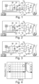
- Fig. 1 shows a first exemplary embodiment of an extracorporeal blood treatment machine (dialysis machine) 1 according to the invention with a dialyzer 2, which has a dialysis fluid inlet 4 and a dialysis fluid outlet 6.
- the dialyzer 2 is further equipped with a filter membrane 8, which separates a dialysis fluid membrane side 10, which is in fluid communication with a dialysis fluid inlet line 12 and a dialysis fluid outlet line 14 of a dialysis fluid circuit 16, from a blood membrane side 18.
- the dialysis fluid inlet line 12 and the dialysis fluid outlet line 14 are connected to the dialysis fluid inlet 4 and the dialysis fluid outlet 6 of the dialyzer 2.
- the blood membrane side 18 is in fluid communication with an extracorporeal blood circuit 20.
- a bypass line 22 is also provided in the dialysis fluid circuit 16, with which the dialysis fluid membrane side 10 of the dialyzer 2 can be bridged, i.e. bypassed in terms of flow.
- a valve 24, 26 is provided in the dialysis fluid inlet line 12 and the dialysis fluid outlet line 14, with which the dialysis fluid inlet line 12 and the dialysis fluid outlet line 14 can be opened or closed and thus either the flow path for fresh dialysis fluid with the valves 24, 26 open through the dialysis fluid inlet line 12 , the dialysis fluid membrane side 10 of the dialyzer 2 and the dialysis fluid drain line 14 release, or by closing at least the valve 24, ideally both valves 24, 26, close this flow path.
- a sensor device 28 is located downstream of the dialysis fluid outlet 6 and upstream of the valve 26.
- This is designed, for example, as an optical sensor device and detects the dialysis fluid flowing past by means of UV/VIS spectroscopy depending on the absorption range of the specific blood component to be measured Measurements at the wavelength that can be absorbed by this blood component in order to enable a concentration determination of this blood component or a corresponding parameter determination. Concentration/characteristic determinations by absorption measurement are generally known and will therefore not be explained in more detail here.
- alternative measuring methods for example by determining conductivity, are also conceivable.
- the measured values generated on the sensor device 28 are transmitted to a control and computing unit 30 and evaluated by it.
- the control and computing unit 30 is in mutual exchange of information at least with the valves 24, 26 and the sensor device 28, i.e. it receives and sends information from the valves 24, 26 and the sensor device 28 or to the valves 24, 26 and the sensor device 28 Furthermore, the control and computing unit 30 is connected or equipped with a storage unit 32. At least one data set is stored or can be stored on this storage unit 32, with which the dialysis machine 1 can be controlled depending on the specified or received information.
- the dialysis machine 1 also has a further valve 34 in the bypass line 22, which is also in information exchange contact with the control and computing unit 30 and can be controlled by it, i.e. opened and closed.
- the valve 34 is provided to open or block the flow path for fresh dialysis fluid via the bypass line 22.
- the fresh dialysis fluid is obtained from a dialysis fluid supply unit/dialysis fluid source 36. Downstream of the dialysis fluid source 36 there is a balancing chamber 38, which balances fresh dialysis fluid flowing into the dialysis fluid circuit 16 and (used) dialysis fluid flowing out of it.
- the balancing chamber 38 is arranged in terms of flow technology so that it is located between the dialysis fluid source 36 and an opening point of the bypass line 22 into the dialysis fluid supply line 12 and between an opening point of the bypass line 22 into the dialysis fluid drain line 14 and a cast.
- the extracorporeal blood circuit 20 is connected to the dialyzer 2 on the blood membrane side 18 of the dialyzer 2.
- the blood circuit 20 has at least one arterial blood line 40, which connects an arterial patient access to a blood-side dialyzer inlet and on which a blood pump 42 is arranged, and a venous blood line 44, which connects a blood-side dialyzer outlet to a venous patient access.
- the blood pump 42 is also in (mutual) information exchange contact with the control and computing unit 30 and is controlled by it.
- Fig. 2 shows a second exemplary embodiment of a dialysis machine 1 according to the invention, which differs from the dialysis machine 1 of the first exemplary embodiment only in that the sensor device 28 is not arranged upstream of the valve 26, but is fluidically located between the valve 26 and the balance chamber 38, in particular between the mouth point the bypass line 22 in the dialysis fluid drain line 14 and the balancing chamber 38.
- Fig. 3 shows a third exemplary embodiment of a dialysis machine 1 according to the invention, which differs from the dialysis machine 1 of the first exemplary embodiment only in that the sensor device 28 is not arranged upstream of the valve 26, but is located downstream of the balancing chamber 38.
- a patient is first connected to the extracorporeal blood circuit 20.
- the control and computing unit 30 retrieves a target blood flow value and a time value for the duration of a bypass mode from the data record stored on the storage unit 32.
- Patient-dependent minimum and maximum upper limits for the target blood flow value can be taken into account in the data set.
- the time value for the duration of the bypass mode is preferably selected/determined such that a (near) diffusion equilibrium is achieved during the bypass mode even under the worst circumstances, namely a maximum possible or maximum expected recirculation (e.g. recirculation of 20% to 30%) for the blood component to be measured in the dialyzer 2 is achieved.
- the time value output can also be larger or smaller.
- the control and computing unit 30 After the control and computing unit 30 has retrieved the target time value and the target blood flow value or these have been entered manually, it sets the blood pump 42 to the target blood flow value. If the target blood flow value is reached and a predetermined value for the dialysis fluid flow through the dialysis fluid circuit 16 is also reached, the dialysis machine 1 is switched into bypass mode by the control and computing unit 30. This means that for the period of the bypass mode, the valves 24, 26 are closed, i.e. the dialysis fluid located between the valves 24, 26 is locked, and the valve 34 in the bypass line 22 is open, so that the flow path of the fresh dialysis fluid from the dialysis fluid source 36 leads to the casting via the bypass line 22.
- the blood pump 42 is now operated at the set rate while the dialysis fluid is on the dialysis fluid membrane side 10.
- the blood component to be measured/determined passes from the blood flowing through the blood membrane side 18 of the dialyzer 2 via the filter membrane 8 into the dialysis fluid standing on the dialysis fluid membrane side 10 of the dialyzer 2.
- the blood component to be measured/determined thus accumulates in the standing dialysis fluid until a diffusion equilibrium is (essentially) reached on the blood membrane side 18 and the dialysis fluid membrane side 10.
- the diffusion equilibrium concentration of the blood component to be measured/determined in the standing dialysis fluid at this time essentially corresponds to the concentration of the blood component to be measured/determined present in the blood of the extracorporeal blood circuit 20, which in turn corresponds to the concentration of the blood component to be measured in the blood of the patient's body. Consequently, the diffusion equilibrium concentration of the blood component to be measured/determined in the standing dialysis fluid corresponds to the concentration of the blood component to be measured present in the blood of the patient's body.
- the control and computing unit 30 cancels the bypass mode. Consequently, it closes the valve 34 in the bypass line 22 and at the same time opens the valves 24, 26 in the dialysis fluid inlet line 12 and the dialysis fluid outlet line 14, so that fresh Dialysis fluid from the dialysis fluid source 36 flows again through the dialysis fluid membrane side 10 of the dialyzer 2.
- the dialysis fluid previously standing on the dialysis fluid membrane side 10 consequently flows through the dialysis fluid drain line 14 in the direction of the cast, passing the sensor device 28.
- this measures a peak (light absorption peak representative of the concentration of this blood component), the maximum of which can be evaluated as the diffusion equilibrium concentration of the blood component.
- the concentration of the blood component to be measured/determined in the blood of the patient's body is known and the actual recirculation can be calculated in a known way during the subsequent or continued blood treatment.
- Fig. 4 shows the time course of the measurement recording (absorption value of the blood component to be measured) on a sensor device 28 of a dialysis machine 1, in which the sensor device 28 is arranged directly behind the valve 26 of the dialysis fluid drain line 14 and in front of or behind the opening point of the bypass line 22 into the dialysis fluid drain line 14 (the time offset of the peak when the sensor device 28 is displaced in the downstream direction is in the Fig. 4 For the sake of simplicity, this is not taken into account as negligible).
- the area marked with a square is the period in which the bypass mode is active, i.e. no dialysis fluid flowing from the dialysis fluid membrane side 10 flows past the sensor device 28.
- the sensor device 28 Before and during the bypass mode, the sensor device 28 therefore measures a constant parameter for the concentration in the dialysis fluid for a specific blood component, since the dialysis fluid or the dialysis fluid fraction, in which the blood component to be measured accumulates as a result of diffusion, between the valves 24, 26 is locked and fresh dialysis fluid from the dialysis fluid source 36 does not flow around the sensor device.
- the concentration measured in this way can be viewed as the concentration of the blood component to be measured at the dialyzer outlet under the normal, known treatment/operating conditions (c do ).
- the sensor device measures a clear peak in the concentration of the blood component to be measured, since after opening the valve 26, the previously trapped dialysis fluid fraction now flows past the sensor device 28. It should be noted here that in the case in which the sensor device 28 is arranged directly behind the valve 26, the peak maximum is almost Diffusion equilibrium concentration corresponds. If there is a greater distance between the valve 26 and the sensor device 28, the peak maximum decreases as a result of diffusion, so that appropriate mathematical correction measures are used to determine the diffusion equilibrium concentration.
- the measured/determined diffusion equilibrium concentration of the blood component to be measured corresponds to the systemic blood component concentration c sys .
- the concentration bolus of the blood component to be measured/determined in the dialysis fluid has completely passed through the sensor device 28, the measured/determined concentration of the blood component again corresponds to c do .
- the recirculation R can now be calculated using the known equation (5) as described above.
Description
Die Erfindung betrifft eine Vorrichtung zur Rezirkulationsmessung bei einer extrakorporalen Blutbehandlung, beispielsweise Hämodialyse, Hämofiltration und /oder Hämodiafiltration.The invention relates to a device for measuring recirculation during extracorporeal blood treatment, for example hemodialysis, hemofiltration and/or hemodiafiltration.
Bei einer extrakorporalen Blutbehandlung, beispielsweise einer Blutreinigung in Form einer Hämodialyse, Hämofiltration oder Hämodiafiltration, wird einem Dialysepatienten Blut über einen arteriellen Gefäßzugang entnommen, in einem Dialysator behandelt und dem Patienten anschließend über einen venösen Gefäßzugang zurückgegeben. Bei chronisch kranken Patienten werden die extrakorporalen Blutbehandlungen so häufig vorgenommen, dass sich die Vene, über die das Blut nach der Behandlung zurückgegeben wird, auf Dauer entzünden und verkleben würde. Aus diesem Grund wird solchen Patienten operativ ein sogenannter Shunt angelegt, welcher eine Querverbindung zwischen der Arterie und der Vene des Patienten darstellt und als dauerhafte Punktionsstelle verwendet wird. In Folge des Shunts verdickt sich die Gefäßwand der Vene, sodass diese sich leichter punktieren lässt und damit einen einfacheren Zugang für die Dialyse ermöglicht. In den meisten Fällen wir ein solcher Shunt in den Arm eines Patienten integriert.In an extracorporeal blood treatment, for example blood purification in the form of hemodialysis, hemofiltration or hemodiafiltration, blood is taken from a dialysis patient via an arterial vascular access, treated in a dialyzer and then returned to the patient via a venous vascular access. In chronically ill patients, extracorporeal blood treatments are carried out so frequently that the vein through which the blood is returned after the treatment would become permanently inflamed and sticky. For this reason, a so-called shunt is surgically created in such patients, which represents a cross connection between the patient's artery and vein and is used as a permanent puncture site. As a result of the shunt, the vessel wall of the vein thickens, making it easier to puncture and thus enabling easier access for dialysis. In most cases, such a shunt is integrated into a patient's arm.
Über die Querverbindung zwischen Arterie und Vene kommt es jedoch auch zu einem Blutaustausch von venösem und arteriellem Blut, insbesondere wenn während der Blutbehandlung der Blutfluss an der Blutpumpe zu hoch eingestellt ist und infolgedessen das in den Shunt des Patienten zurückzufördernde Blut teilweise in den arteriellen Gefäßzugang des Patienten übertritt. Folglich verdünnt also das bereits gereinigte, venöse Blut das noch ungereinigte, arterielle Blut, sodass es zu einer Beeinträchtigung der Blutbehandlungseffizienz bzw. des Wirkungsgrads der Blutbehandlung kommt. Dadurch wird die Behandlungszeit verlängert. Ein solcher Vorgang, bei dem das bereits gereinigte sowie in den Patienten zurückgeförderte Blut aus der Patientenvene über den Gefäßzugang, bspw. Shunt, in die Arterie einströmt und vor dort erneut in den extrakorporalen Blutkreislauf gelangt, wird als Rezirkulation bezeichnet und kann anhand unterschiedlicher Methoden qualitativ sowie quantitativ bestimmt werden. Eine quantitative Rezirkulationsmessung wird unter anderem zur Überwachung des Shuntzustands und der Überprüfung der Blutbehandlungseinstellungen, beispielsweise die Förderrate der Blutpumpe, eingesetzt.However, blood exchange of venous and arterial blood also occurs via the cross connection between artery and vein, especially if the blood flow at the blood pump is set too high during the blood treatment and as a result the blood to be returned to the patient's shunt partially flows into the arterial vascular access patient passes. Consequently, the already purified venous blood dilutes the still unpurified arterial blood, so that the blood treatment efficiency or the effectiveness of the blood treatment is impaired. This extends the treatment time. Such a process in which the already cleaned as well as in the patient Returned blood from the patient's vein flows into the artery via the vascular access, e.g. shunt, and then returns to the extracorporeal blood circulation, is referred to as recirculation and can be determined qualitatively and quantitatively using various methods. A quantitative recirculation measurement is used, among other things, to monitor the shunt status and check the blood treatment settings, for example the delivery rate of the blood pump.
Aus dem Stand der Technik sind mehrere unterschiedliche Methoden zur Bestimmung des Rezirkulationsanteils bekannt. Ein häufig angewandtes Verfahren sieht beispielsweise die Erzeugung eines definierten Temperaturbolus vor, welcher im venösen Blutzweig aufgegeben wird, mit anschließender Temperaturmessung im arteriellen Zweig, sodass basierend auf der aufgegebenen Temperaturdifferenz und der gemessenen Temperaturdifferenz mathematisch ein Rückschluss auf die Rezirkulationsquote gebildet werden kann. Ebenso ist es bekannt, anstelle der Temperatur einen anderen Indikator, beispielsweise eine bestimmte Stoffkonzentration oder die Leitfähigkeit, zu messen, der zuvor in Form eines (Indikator-) Bolus aufgegeben wurde. Auch kann der Bolus dialysierflüssigkeitsseitig stromauf des Dialysators aufgegeben werden und dialysierflüssigkeitsseitig stromab des Dialysators eine entsprechende Messung durchgeführt werden, aus der die Rezirkulation bestimmbar ist.Several different methods for determining the recirculation fraction are known from the prior art. A frequently used method, for example, provides for the generation of a defined temperature bolus, which is applied in the venous blood branch, with subsequent temperature measurement in the arterial branch, so that a conclusion about the recirculation rate can be formed mathematically based on the applied temperature difference and the measured temperature difference. It is also known to measure another indicator instead of the temperature, for example a specific substance concentration or conductivity, which was previously applied in the form of an (indicator) bolus. The bolus can also be applied on the dialysis fluid side upstream of the dialyzer and a corresponding measurement can be carried out on the dialysis fluid side downstream of the dialyzer, from which the recirculation can be determined.
Aus der Patentschrift
Auch in
Als weiteres Beispiel beschreibt die Patentanmeldung
Weiter offenbart die Patentanmeldung
Weiter sind Verfahren zur Rezirkulationsbestimmung bekannt, bei denen die Rezirkulation anhand der folgenden Gleichung berechnet wird: 
Die Rezirkulationsrate R wird im Allgemeinen nach folgender Gleichung bestimmt:

- R Rezirkulationsrate (0...1 bzw. 0...100%)
- KE effektive Clearance
- KD theoretische Clearance des Dialysators
- QB Blutflussrate im extrakorporalen Blutschlauchsystem (bekannt, da an der Maschine einstellbar)
- (vgl.
DE 10 2013 103 221 A1
- R recirculation rate (0...1 or 0...100%)
- K E effective clearance
- K D theoretical clearance of the dialyzer
- Q B Blood flow rate in the extracorporeal blood tubing system (known because it can be adjusted on the machine)
- (see.
DE 10 2013 103 221 A1
Falls die Rezirkulation 0 ist, gilt KE = KD. Der Wert KE kann demnach rezirkulationsbehaftet sein.If recirculation is 0, K E = K D . The value K E can therefore be subject to recirculation.
- QD Dialysierflüssigkeitsflussrate (bekannt, da an der Maschine einstellbar)
- cDO Konzentration eines Stoffes am Dialysatausgang
- cBI Konzentration eines Blutanteilsstoffes im arteriellen Zweig des Blutschlauchsystems
- csys systemische Konzentration eines Blutanteilsstoffes, welche nicht rezirkulationsbehaftet ist. (Konzentration im Patienten)
- Q D Dialysis fluid flow rate (known as it can be set on the machine)
- c DO concentration of a substance at the dialysate outlet
- c BI concentration of a blood component in the arterial branch of the blood tubing system
- c sys systemic concentration of a blood component that is not affected by recirculation. (concentration in the patient)
Somit lässt sich die effektive Clearance durch Umstellen von Gleichung (2) bestimmen zu:
![]()
![]()
Nach der Gleichung von Michaels (
Der K 0 A-Wert ist für die unterschiedlichen Dialysatoren bekannt und kann bspw. einer im Speicher der Dialysemaschine hinterlegten Lookup-Tabelle entnommen werden.The K 0 A value is known for the different dialyzers and can be found, for example, in a lookup table stored in the memory of the dialysis machine.
Einsetzen der Gleichungen (3) in (1) ergibt:

Hierbei ist KD aus Gleichung (4) bekannt.Here K D is known from equation (4).
Die obigen Zusammenhänge gelten nur für den Fall, dass die Ultrafiltrationsrate zum Zeitpunkt der Messung minimal bzw. null gesetzt wird.The above relationships only apply if the ultrafiltration rate is set to a minimum or zero at the time of measurement.
Bei den bekannten Verfahren, die diese Gleichung (3) zur Rezirkulationsberechnung heranziehen, wird deshalb zur Bestimmung von csys vor der Blutbehandlung zunächst eine Blutprobe des Patienten genommen und csys gemessen. Anschließend kann die Rezirkulation R während der Blutbehandlung über die Gleichung (3) ausgerechnet werden.In the known methods that use this equation (3) to calculate recirculation, to determine c sys , a blood sample is first taken from the patient before the blood treatment and c sys is measured. The recirculation R during blood treatment can then be calculated using equation (3).
Der Stand der Technik hat jedoch immer den Nachteil, dass entweder ein erhöhter apparativer Aufwand, beispielsweise durch Vorsehen von Temperiereinrichtungen oder Einrichtungen für eine Stoff-bzw. Konzentrationsboluszugabe, erforderlich ist oder vor der Behandlung eine separate Blutwertbestimmung durchgeführt werden muss. Des Weiteren ist die Bestimmung von csys anhand einer Patientenblutprobe aufwändig und daher nicht zufriedenstellend.However, the prior art always has the disadvantage that either an increased expenditure on equipment is required, for example by providing temperature control devices or devices for a material or Concentration bolus addition is required or a separate blood value determination must be carried out before treatment. Furthermore, the determination of c sys using a patient's blood sample is time-consuming and therefore not satisfactory.
Es ist somit die Aufgabe der Erfindung, die Nachteile aus dem Stand der Technik zu überwinden oder zumindest zu mildern und insbesondere eine Vorrichtung zur Rezirkulationsmessung bei einer extrakorporalen Blutbehandlung, beispielsweise unter Verwendung eines Shunts, bereitzustellen, die ohne zusätzlichen apparativen Aufwand, beispielsweise einer Temperiereinrichtung, und/oder verfahrenstechnischen Aufwand, wie beispielweise einer separaten Blutprobenentnahme vor der Behandlung, durchführbar ist.It is therefore the object of the invention to overcome or at least mitigate the disadvantages of the prior art and in particular to provide a device for recirculation measurement during extracorporeal blood treatment, for example using a shunt, which can be used without additional equipment, for example a temperature control device. and/or procedural effort, such as taking a separate blood sample before treatment, can be carried out.
Die Aufgabe der Erfindung wird mit einer extrakorporalen Blutbehandlungsmaschine mit den Merkmalen des Anspruchs 1 gelöst.The object of the invention is achieved with an extracorporeal blood treatment machine with the features of
Ein Grundgedanke der Erfindung besteht darin, eine Vorrichtung zur extrakorporalen Blutbehandlung zu schaffen, die dazu eingerichtet ist, die systemische Blutanteilstoff-Konzentration csys (Konzentration eines Anteilsstoffs im Blut des Patientenkörpers) während der Blutbehandlung und insbesondere ausschließlich mit den an einer Vorrichtung zur extrakorporalen Blutbehandlung grundsätzlich vorgesehen Einrichtungen zu bestimmen und die Rezirkulation R dann anhand der vorstehenden, bekannten Gleichung (5) zu ermitteln. Anders ausgedrückt soll csys bestimmt werden können, ohne dass dazu Apparaturen wie beispielsweise eine Temperiereinrichtung zur Erzeugung eines Temperaturbolus oder Einrichtungen zum Injizieren eines Stoffbolus benötigt werden.A basic idea of the invention is to create a device for extracorporeal blood treatment, which is designed to measure the systemic blood component concentration c sys (concentration of a component in the blood of the patient's body) during blood treatment and in particular exclusively with those on a device for extracorporeal blood treatment In principle, devices are to be determined and the recirculation R is then determined using the above, known equation (5). In other words, c sys should be able to be determined without the need for equipment such as a temperature control device for generating a temperature bolus or devices for injecting a substance bolus.
Zu diesem Zweck bedient sich die Erfindung einer vorzugsweise optisch arbeitenden Sensorvorrichtung am oder stromab zu einem dialysierflüssigkeitsseitigen Dialysatorausgang, welche im Allgemeinen zur Erfassung/Bestimmung von bestimmten Blutstoffanteilen wie urämische Toxine (z.B. Harnstoff) in der verbrauchten Dialysierflüssigkeit verwendet werden sowie einer vorzugsweise Dialysemaschine-eigenen elektronischen Steuerung, welche erfindungsgemäß dafür vorgesehen und angepasst ist, die Dialysemaschine in einen Modus zu schalten, in welchem Dialysierflüssigkeit im Dialysator solange eingesperrt wird, bis sich auf der Dialysierflüssigkeitsseite und der Blutseite des Dialysators ein sich nicht mehr (oder unwesentlich) veränderndes Blutanteilsstoff-Konzentrationsgleichgewicht einstellt/eingestellt hat. D.h., während der Einsperrphase nimmt die Reinigung des Blutes im Dialysator ab und geht gegen null, weshalb schließlich ein Diffusionsgleichgewicht zwischen Blut- und Dialysierflüssigkeitsseite herrscht. Rezirkulation spielt hierbei nur insoweit eine Rolle als dass sich die Zeitspanne bis zur Erreichung eines Diffusionsgleichgewichts verändert (verlängert).For this purpose, the invention uses a preferably optically operating sensor device on or downstream of a dialyzer outlet on the dialysis fluid side, which is generally used to detect/determine certain blood substance components such as uremic toxins (e.g. urea) in the used dialysis fluid, as well as an electronic one, preferably the dialysis machine's own Control, which according to the invention is intended and adapted to switch the dialysis machine into a mode in which dialysis fluid is locked in the dialyzer until a no longer (or insignificantly) changing blood component concentration equilibrium is established on the dialysis fluid side and the blood side of the dialyzer / has set. Ie, during the confinement phase, the purification of the blood in the dialyzer decreases and approaches zero, which is why a diffusion equilibrium between blood and dialyzer ultimately occurs Dialysis fluid side prevails. Recirculation only plays a role here insofar as the time required to reach a diffusion equilibrium changes (extends).
Diese im Dialysator temporär eingesperrte Menge an verbrauchter Dialysierflüssigkeit hat demnach eine dem Patientenblut im Wesentlichen entsprechende Blutanteilsstoff-Konzentration und kann dann wie ein Dialysierflüssigkeitsbolus der Sensorvorrichtung zugeführt werden, welche dessen Blutanteilsstoff-Konzentration misst/erfasst. Der Wert csys entspricht erfindungsgemäß dann dem Peak im Sensorsignal der Sensorvorrichtung (unmittelbar) nach der Freigabe des Dialysierflüssigkeitsbolus aus dem Dialysator.This amount of used dialysis fluid temporarily locked in the dialyzer therefore has a blood component concentration that essentially corresponds to the patient's blood and can then be supplied like a dialysis fluid bolus to the sensor device, which measures/detects its blood component concentration. According to the invention, the value c sys then corresponds to the peak in the sensor signal of the sensor device (immediately) after the release of the dialysis fluid bolus from the dialyzer.
An dieser Stelle sei darauf hingewiesen dass unter dem Begriff "im Dialysator eingesperrt" konkret ein Einsperren der Dialysierflüssigkeit auf einer Dialysierflüssigkeitsmembranseite des Dialysators zu verstehen ist. Der Begriff "einsperren" ist darüber hinaus als nicht bzw. im Wesentlichen nicht durchströmend zu verstehen. Weiter umfasst der eingeschlossene Raum u.U. auch noch Teile der Dialysierflüssigkeitszu-/ablaufleitung. Wenn man beispielsweise davon ausgehen würde, dass z.B. durch Aktivierung eines Dialysator-Bypasses mit einem deutlich geringeren Strömungswiderstand (im Vergleich mit dem Dialysator) ein Strömen der Dialysierflüssigkeit durch den Dialysator unterbrochen bzw. im Wesentlichen unterbrochen wird, könnte auf die dicht abschließende Ventile für eine solche Bypassschaltung verzichtet werden. In diesem Fall wäre die Flüssigkeit nicht wirklich ,eingesperrt' sondern die Durchströmung des Dialysators mit Dialysierflüssigkeit wäre auf nahe Null reduziert.At this point it should be noted that the term “locked in the dialyzer” specifically means locking up the dialysis fluid on a dialysis fluid membrane side of the dialyzer. The term “lock in” is also to be understood as not or essentially not flowing through. The enclosed space may also include parts of the dialysis fluid inlet/outlet line. If, for example, one were to assume that, for example, by activating a dialyzer bypass with a significantly lower flow resistance (compared to the dialyzer), a flow of dialysis fluid through the dialyzer is interrupted or essentially interrupted, one could refer to the tightly sealing valves for one Such a bypass circuit can be dispensed with. In this case, the liquid would not really be 'locked in' but rather the flow of dialysate fluid through the dialyzer would be reduced to almost zero.
Konkret ist erfindungsgemäß eine extrakorporale Blutbehandlungsmaschine, insbesondere Hämodialyse-, Hämofiltrations- oder Hämodiafiltrationsmaschine, vorgesehen (nachfolgend auch allgemein als Dialysemaschine bezeichnet) mit einem Dialysator, der einen Dialysierflüssigkeitszulauf für frische Dialysierflüssigkeit und einen Dialysierflüssigkeitsablauf für verbrauchte Dialysierflüssigkeit aufweist und der weiter mit einer Filtermembran ausgestattet ist, welche eine Dialysierflüssigkeitsmembranseite, auf der der Dialysator über eine Dialysierflüssigkeitszulaufleitung und eine Dialysierflüssigkeitsablaufleitung an einen Dialysierflüssigkeitskreis(lauf) angeschlossen ist, von einer Blutmembranseite trennt, auf der der Dialysator an einen extrakorporalen Blutkreis(lauf) angeschlossen oder anschließbar ist. Die erfindungsgemäße Dialysemaschine weist weiter bevorzugt eine Bypassleitung auf, mittels derer die Dialysierflüssigkeitsmembranseite wahlweise in einem Kurzschlussmodus überbrückbar ist, um im Dialysator befindliche Dialysierflüssigkeit temporär einzusperren. Hierzu ist an der Dialysierflüssigkeitszulaufleitung und der Dialysierflüssigkeitsablaufleitung wenigstens jeweils ein (Sperr)Ventil zwischen der Bypassleitung und dem Dialysator angeordnet. Weiter ist die erfindungsgemäße Dialysemaschine mit einer Sensorvorrichtung am oder stromab des Dialysierflüssigkeitsablaufs des Dialysators ausgestattet, die dazu angepasst ist, durch die Filtermembran hindurchgetretene Blutanteilsstoffe, insbesondere urämische Toxine (bspw. Harnstoff, Kreatinin, Harnsäure, Kalium etc.), in der aus dem Dialysator ablaufenden, verbrauchten Dialysierflüssigkeit messtechnisch, insbesondere optisch, zu erfassen. Generell ist an dieser Stelle anzumerken, dass mit dem Sensor eine physikalische oder chemische Größe gemessen wird, die zur Konzentration eines bestimmten Stoffes proportional sein kann. Tatsächliche bzw. unmittelbar gemessene Konzentrationswerte benötigt das vorgeschlagene Verfahren zur Rezirkulationsmessung nicht. Die erfindungsgemäße Dialysemaschine weist weiter eine Steuer- und Recheneinheit zur Steuerung der Dialysemaschine vorzugsweise mit einer Speichereinheit auf. Dabei ist die Dialysemaschine vorzugsweise weiter mit einem auf der Speichereinheit oder einem vergleichbaren separaten Speichermedium abgelegten oder ablegbaren Datensatz ausgestattet oder bestückbar, der zumindest für den aktuell angeschlossenen Dialysator einen Blutstromwert im extrakorporalen Blutkreis und einen zugehörigen, vorzugsweise analytisch bestimmten, Zeitwert umfasst, wobei der Blutstrom- und Zeitwert und/oder die Identität bzw. die Eigenschaften des angeschlossenen Dialysators natürlich auch manuell eingegeben, eingescannt oder auf andere Weise eingespeist werden könnten. Innerhalb dieses durch den Zeitwert bestimmten Zeitraums ist im Dialysator bei eingestelltem Blutstromwert unter der Annahme eines maximal möglichen Rezirkulationswerts (z.B. 20%) ein Konzentrationsausgleich zumindest eines ausgewählten oder auswählbaren Blutanteilsstoffs zwischen Blut im extrakorporalen Blutkreis und im Dialysator eingesperrter Dialysierflüssigkeit ausschließlich infolge von Diffusion beendet. Die Dialysemaschine verfügt dabei weiter über ein (auf der Speichereinheit abgelegtes) Berechnungsmodell, anhand welchem die Steuer- und Recheneinheit beispielsweise unter Berücksichtigung einer Konzentration des zumindest einen ausgewählten oder auswählbaren Blutanteilsstoffs im Blut des Patienten(körpers) oder einer Absorbanz (weil Konzentration zu Absorbanz äquivalent ist), vorzugsweise zu Beginn eines Behandlungszyklus mittels der Dialysemaschine, einen tatsächlichen Rezirkulationswert berechnet. Dafür schaltet die Steuer- und Recheneinheit zur Bestimmung des zumindest einen ausgewählten oder auswählbaren Blutanteilsstoffs im Blut des Patienten(körpers) die Dialysemaschine für die Dauer des im Datensatz angegebenen oder manuell (einschließlich Scann) eingegebenen Zeitwerts in den Kurzschlussmodus und betreibt den extrakorporalen Blutkreis, vorzugsweise gleichzeitig, bei dem angegebenen Blutstromwert und erfasst unmittelbar nach Beendigung des Kurzschlussmodus mithilfe der Sensorvorrichtung messtechnisch einen durch den Kurzschlussmodus entstandenen Konzentrationsbolus bzw. einen hierfür stehenden Messparameter in der aus dem Dialysator ablaufenden, verbrauchten Dialysierflüssigkeit.Specifically, according to the invention, an extracorporeal blood treatment machine, in particular a hemodialysis, hemofiltration or hemodiafiltration machine, is provided (hereinafter also generally referred to as a dialysis machine) with a dialyzer which has a dialysis fluid inlet for fresh dialysis fluid and a dialysis fluid outlet for used dialysis fluid and which is further equipped with a filter membrane , which separates a dialysis fluid membrane side, on which the dialyzer is connected to a dialysis fluid circuit (run) via a dialysis fluid inlet line and a dialysis fluid drain line, from a blood membrane side, on which the dialyzer is connected or can be connected to an extracorporeal blood circuit (run). The dialysis machine according to the invention further preferably has a bypass line, by means of which the dialysis fluid membrane side can optionally be bridged in a short-circuit mode in order to temporarily lock in dialysis fluid located in the dialyzer. For this purpose, at least one (blocking) valve is arranged on the dialysis fluid inlet line and the dialysis fluid outlet line between the bypass line and the dialyzer. Next is the dialysis machine according to the invention is equipped with a sensor device on or downstream of the dialysis fluid outlet of the dialyzer, which is adapted to detect blood components that have passed through the filter membrane, in particular uremic toxins (e.g. urea, creatinine, uric acid, potassium, etc.), in the blood that flows out of the dialyzer, to measure the used dialysis fluid, especially optically. In general, it should be noted at this point that the sensor measures a physical or chemical quantity that can be proportional to the concentration of a specific substance. The proposed method for recirculation measurement does not require actual or directly measured concentration values. The dialysis machine according to the invention further has a control and computing unit for controlling the dialysis machine, preferably with a memory unit. The dialysis machine is preferably further equipped or can be equipped with a data set which is stored or can be stored on the storage unit or a comparable separate storage medium and which comprises, at least for the currently connected dialyzer, a blood flow value in the extracorporeal blood circuit and an associated, preferably analytically determined, time value, the blood flow - and time value and/or the identity or properties of the connected dialyzer could of course also be entered manually, scanned or fed in in some other way. Within this period determined by the time value, a concentration equalization of at least one selected or selectable blood component between blood in the extracorporeal blood circuit and dialysis fluid trapped in the dialyzer is completed in the dialyzer with the blood flow value set, assuming a maximum possible recirculation value (e.g. 20%), exclusively as a result of diffusion. The dialysis machine also has a calculation model (stored on the storage unit) which the control and computing unit uses, for example, taking into account a concentration of the at least one selected or selectable blood component in the blood of the patient (body) or an absorbance (because concentration is equivalent to absorbance is), preferably at the beginning of a treatment cycle using the dialysis machine, an actual recirculation value is calculated. For this purpose, the control and computing unit for determining the at least one selected or selectable blood component in the blood of the patient (body) switches the dialysis machine to short-circuit mode for the duration of the time value specified in the data record or entered manually (including scanning) and operates the extracorporeal blood circuit, preferably at the same time, at the specified blood flow value and, immediately after the end of the short-circuit mode, uses the sensor device to measure a concentration bolus or a measurement parameter for this purpose in the used dialysis fluid flowing out of the dialyzer.
In anderen Worten wird zur Bestimmung einer tatsächlichen Rezirkulation während einer Blutbehandlung zunächst die Dialysemaschine temporär in einem Bypassmodus betrieben. In diesem Bypassmodus wird die Dialysierflüssigkeitsseite im Dialysator nicht mit frischer Dialysierflüssigkeit versorgt bzw. die Filtermembran dialysierflüssigkeitsseitig nicht mit frischer Dialysierflüssigkeit umspült. Vielmehr wird die auf der Dialysierflüssigkeitsmembranseite vorhandene Dialysierflüssigkeit dort gehalten, vorzugsweise unter Einsatz von Ventilen, die in der Dialysierflüssigkeitszulaufleitung und der Dialysierflüssigkeitsablaufleitung angeordnet sind. Anstelle von Ventilen sind selbstverständlich auch andere zur Fluidabsperrung geeignete Elemente, beispielsweise Pumpen, denkbar. Während nun die auf der Dialysierflüssigkeitsmembranseite befindliche Dialysierflüssigkeit dort gehalten wird, wird der Blutstrom im extrakorporalen Blutkreis mit einer festgelegten Blutstromrate betrieben. Die Blutseite des Dialysators wird also weiter mit arteriellem bzw. zu reinigendem Blut versorgt bzw. die Filtermembran blutseitig weiter mit arteriellem bzw. zu reinigendem Blut umspült. Folglich findet nun, wie bei Dialysebehandlungen üblich, aufgrund von Diffusion ein Übertritt von im Blut gelösten Stoffen (Blutanteilsstoffen) durch die Filtermembran in die Dialysierflüssigkeit statt, und zwar solange, bis kein Konzentrationsgradient mehr zwischen dem auf der Blutseite vorhandenen Blut und der auf der Dialysierflüssigkeitsseite vorhandenen Dialysierflüssigkeit vorliegt, also in anderen Worten ein Diffusionsgleichgewicht erreicht ist. Da das Blut auf der Blutmembranseite des Dialysators weiter strömt, während die Dialysierflüssigkeit auf der Dialysierflüssigkeitsmembranseite des Dialysators steht, reichern sich in der stehenden Dialysierflüssigkeit solange Blutanteilsstoffe weiter an, bis diese in der stehenden Dialysierflüssigkeit zumindest im Wesentlichen dieselbe Konzentration erreicht haben wie im weiter durch den Dialysator strömenden Blut. In anderen Worten entspricht zu dem Zeitpunkt, an dem das Diffusionsgleichgewicht eines Blutanteilsstoffs zwischen der stehenden Dialysierflüssigkeit und dem strömenden Blut (im Wesentlichen) erreicht ist, die Konzentration des in der stehenden Dialysierflüssigkeit gelösten Blutanteilsstoffs zumindest im Wesentlichen der Konzentration des im Blut des Patientenkörpers gelösten Blutanteilsstoffs. An dieser Stelle sei darauf hingewiesen, dass der Parameter "Konzentration" auch durch einen mit diesem zusammenhängenden anderen Parameter repräsentiert sein kann wie beispielsweise eine Absorbance oder eine messbare elektrische Leitfähigkeit. Zur Berechnung der tatsächlichen Rezirkulation kann also mit Erreichen des Diffusionsgleichgewichts die in der stehenden Dialysierflüssigkeit vorliegende (direkt oder indirekt messbare/bestimmbare) Konzentration eines Blutanteilsstoffs ersatzweise für die im Blut des Patientenkörpers vorliegende Konzentration csys dieses Blutanteilsstoffs hergenommen werden. Um eine etwaige Überschreitung des linearen Sensormessbereiches zu kompensieren, kann zusätzlich ein Kompensationsfaktor k genutzt werden. K kann hierbei durch eine Funktion ermittelt werden, die die Kennlinie des Sensors analytisch beschreibt.In other words, to determine actual recirculation during blood treatment, the dialysis machine is first temporarily operated in a bypass mode. In this bypass mode, the dialysis fluid side in the dialyzer is not supplied with fresh dialysis fluid or the filter membrane on the dialysis fluid side is not flushed with fresh dialysis fluid. Rather, the dialysis fluid present on the dialysis fluid membrane side is held there, preferably using valves that are arranged in the dialysis fluid inlet line and the dialysis fluid outlet line. Instead of valves, other elements suitable for shutting off fluid, such as pumps, are of course also conceivable. While the dialysis fluid located on the dialysis fluid membrane side is now held there, the blood flow in the extracorporeal blood circuit is operated at a fixed blood flow rate. The blood side of the dialyzer is therefore further supplied with arterial blood or blood to be cleaned or the filter membrane on the blood side is further washed with arterial blood or blood to be cleaned. Consequently, as is usual in dialysis treatments, due to diffusion, substances dissolved in the blood (blood components) pass through the filter membrane into the dialysis fluid until there is no longer a concentration gradient between the blood present on the blood side and that on the dialysis fluid side existing dialysis fluid is present, i.e. in other words a diffusion equilibrium is reached. Since the blood continues to flow on the blood membrane side of the dialyzer while the dialysis fluid is on the dialysis fluid membrane side of the dialyzer, blood components continue to accumulate in the standing dialysis fluid until they have at least essentially reached the same concentration in the standing dialysis fluid as in the further Dialyzer flowing blood. In other words, at the point in time at which the diffusion equilibrium of a blood component between the standing dialysis fluid and the flowing blood is (substantially) reached, the concentration of the blood component dissolved in the standing dialysis fluid corresponds at least substantially to the concentration of the blood component dissolved in the blood of the patient's body . At this point it should be noted that the parameter “concentration” can also be represented by another parameter related to it, such as an absorbance or a measurable electrical conductivity. When the diffusion equilibrium is reached, the concentration present in the standing dialysis fluid (which can be measured/determined directly or indirectly) can be used to calculate the actual recirculation of a blood component can be used as a substitute for the concentration c sys of this blood component present in the blood of the patient's body. In order to compensate for any overshoot of the linear sensor measuring range, a compensation factor k can also be used. K can be determined using a function that analytically describes the characteristic curve of the sensor.
Der Zeitpunkt, an dem ein Diffusionsgleichgewicht erreicht ist, hängt neben dem konkreten Blutanteilsstoff, beispielsweise ein bestimmtes urämisches Toxin, ggf. auch vom Wirkungsgrad der Blutbehandlung ab, also von der tatsächlich vorliegenden Rezirkulation. Ist die Rezirkulation nur gering ausgeprägt oder gar nicht vorhanden, wird das Diffusionsgleichgewicht ggf. schneller erreicht, als wenn die Rezirkulation hoch ausfällt, da rezirkuliertes Blut zu einer Verdünnung des zu reinigenden, arteriellen Bluts führt und somit die Effizienz der Blutreinigung beeinträchtigt. Die Dauer bis zum Erreichen des Diffusionsgleichgewichts zwischen der Blut- und der Dialysierflüssigkeitsseite ist maßgeblich aber abhängig vom eingestellten Blutfluss und der Dialysatorgröße. Je größer der Blutfluss und je kleiner der Dialysator, desto schneller wird ein diffusives Gleichgewicht erreicht.The point in time at which a diffusion equilibrium is reached depends not only on the specific blood component, for example a specific uremic toxin, but also on the efficiency of the blood treatment, i.e. on the actual recirculation. If recirculation is low or not present at all, the diffusion equilibrium may be reached more quickly than if recirculation is high, since recirculated blood leads to a dilution of the arterial blood to be purified and thus impairs the efficiency of blood purification. The time it takes to reach the diffusion equilibrium between the blood and dialysis fluid sides depends largely on the set blood flow and the size of the dialyzer. The greater the blood flow and the smaller the dialyzer, the faster a diffusive equilibrium is achieved.
Die Höhe der Rezirkulation hat dagegen einen Einfluss darauf, wie lange es dauert, bis die arterielle Blutkonzentration cBI der systemischen Konzentration cSYS entspricht. Im Falle einer nicht vorliegenden Rezirkulation entspricht cBI nahezu cSYS. Es ist daher davon auszugehen, dass dieser Vorgang weniger Zeit beansprucht als die oben erwähnte Herstellung des Diffusionsgleichgewichts.The level of recirculation, on the other hand, has an influence on how long it takes until the arterial blood concentration cBI corresponds to the systemic concentration cSYS. In the case of no recirculation, cBI is almost equivalent to cSYS. It can therefore be assumed that this process takes less time than the establishment of the diffusion equilibrium mentioned above.
Um nun sicherzustellen, dass die Dauer des Bypassmodus auch tatsächlich mindestens der Dauer, bis zu der sich das Diffusionsgleichgewicht eines bestimmten Blutanteilsstoffs im Dialysator eingestellt hat, entspricht, muss die Zeitdauer des Bypassmodus stets auf die Maximaldauer der Diffusionsgleichgewichtseinstellung ausgelegt werden. Diese wird der Steuer- und Recheneinheit vorab zur Verfügung gestellt, entweder durch Abruf der Information aus einer Datenbank / einem Datensatz oder durch Eingabe eines Benutzers, und kann abhängig vom Patienten, dessen Shuntzustand und/oder weiteren spezifischen Erfahrungswerten sein, beispielsweise empirische Ermittlung im Labor oder Auswertung von vergangenen Blutbehandlungen.In order to ensure that the duration of the bypass mode actually corresponds at least to the duration up to which the diffusion equilibrium of a specific blood component has been established in the dialyzer, the duration of the bypass mode must always be designed for the maximum duration of the diffusion equilibrium setting. This is made available to the control and computing unit in advance, either by retrieving the information from a database/data set or by entering it from a user, and can depend on the patient, their shunt condition and/or other specific empirical values, for example empirical determination in the laboratory or evaluation of past blood treatments.
Die Dauer des Bypassmodus bzw. die zu erwartende Dauer bis zur Diffusionsgleichgewichtseinstellung im Dialysator ist weiter davon abhängig, was für ein Dialysator verwendet wird, beispielsweise vom Zustand (neu oder wiederverwendet) und/oder der (verfügbaren) Filterfläche und/oder des (dialysatseitigen) Füllvolumens, und mit welcher Strömungsrate das zur reinigende Blut durch den Dialysator geführt wird. Deshalb steht der Steuer- und Recheneinheit ein Datensatz zur Verfügung, aus dem sich die Soll-Dauer des Bypassmodus und die einzustellende Soll-Blutflussrate unter Berücksichtigung der maximal möglichen Rezirkulation und der Eigenschaften des konkret verwendeten / angeschlossenen Dialysators ermitteln lassen. Es ist alternativ auch denkbar, dass die Soll-Dauer des Bypassmodus auch in Abhängigkeit einer vorbestimmten Blutströmungsrate ermittelt wird.The duration of the bypass mode or the expected duration until the diffusion equilibrium is set in the dialyzer is further dependent on what kind of dialyzer is used, for example on the condition (new or reused) and/or the (available) filter area and/or the (dialysate side) filling volume, and at what flow rate the blood to be cleaned is passed through the dialyzer. The control and computing unit therefore has a data set available from which the target duration of the bypass mode and the target blood flow rate to be set can be determined, taking into account the maximum possible recirculation and the properties of the specific dialyzer used/connected. Alternatively, it is also conceivable that the target duration of the bypass mode is also determined depending on a predetermined blood flow rate.
Ist die Soll-Dauer des Bypassmodus dann erreicht und liegt folglich im Dialysator ein Diffusionsgleichgewicht für einen bestimmten Blutanteilsstoff zwischen Blutseite und Dialysierflüssigkeitsseite im Dialysator vor, wird der Bypassmodus beendet und werden somit die Ventile in Dialysierflüssigkeitszuführleitung und Dialysierflüssigkeitsablaufleitung wieder geöffnet. Mittels der Sensoreinrichtung, welche vorzugsweise stromab des Ventils in der Dialysierflüssigkeitsablaufleitung angeordnet ist, kann nun in der durch die Dialysierflüssigkeitsablaufleitung strömenden Dialysierflüssigkeit die Konzentration des bestimmten Blutanteilsstoffs bestimmt werden, welche der Konzentration des bestimmten Blutanteilsstoffs im Blut des Patientenkörpers entspricht.If the target duration of the bypass mode is then reached and there is consequently a diffusion equilibrium for a certain blood component between the blood side and the dialysis fluid side in the dialyzer, the bypass mode is ended and the valves in the dialysis fluid supply line and dialysis fluid drain line are opened again. By means of the sensor device, which is preferably arranged downstream of the valve in the dialysis fluid drain line, the concentration of the specific blood component can now be determined in the dialysis fluid flowing through the dialysis fluid drain line, which corresponds to the concentration of the specific blood component in the blood of the patient's body.
Vorteilhafterweise kann somit eine tatsächlich vorliegende Rezirkulation bestimmt werden, ohne dass vorab durch separate Blutprobenentnahme am Patienten die Konzentration eines Blutanteilsstoffs im Blut des Patientenkörpers bestimmt werden muss, und folglich kann ein vollautomatisiertes, zeitsparendes und sicheres Blutbehandlungsverfahren ermöglicht werden.Advantageously, an actual recirculation can be determined without the concentration of a blood component in the blood of the patient's body having to be determined in advance by taking a separate blood sample from the patient, and consequently a fully automated, time-saving and safe blood treatment method can be made possible.
Weiter bevorzugt ist die Speichereinheit in der Dialysemaschine fest integriert. Vorteilhafterweise muss somit nicht vor der Behandlung ein externes, zusätzliches Speichermedium, beispielsweise USB-Stick, angeschlossen werden.More preferably, the storage unit is permanently integrated into the dialysis machine. Advantageously, an external, additional storage medium, such as a USB stick, does not have to be connected before the treatment.
Die Erfindung wird nachstehend anhand eines bevorzugten Ausführungsbeispiels unter Bezugnahme auf die beigefügte Zeichnung näher beschrieben. Es zeigen:
-
Fig. 1 ein erstes Ausführungsbeispiel einer erfindungsgemäßen extrakorporalen Blutbehandlungsmaschine; -
Fig. 2 ein zweites Ausführungsbeispiel einer erfindungsgemäßen extrakorporalen Blutbehandlungsmaschine; -
Fig. 3 ein drittes Ausführungsbeispiel einer erfindungsgemäßen extrakorporalen Blutbehandlungsmaschine; -
Fig. 4 einen zeitlichen Verlauf der Messaufnahme an einer Sensorvorrichtung einer Dialysemaschine, bei der die Sensorvorrichtung direkt hinter oder vor dem Ventil der Dialysierflüssigkeitsablaufleitung angeordnet ist.
-
Fig. 1 a first embodiment of an extracorporeal blood treatment machine according to the invention; -
Fig. 2 a second embodiment of an extracorporeal blood treatment machine according to the invention; -
Fig. 3 a third embodiment of an extracorporeal blood treatment machine according to the invention; -
Fig. 4 a time course of the measurement recording on a sensor device of a dialysis machine, in which the sensor device is arranged directly behind or in front of the valve of the dialysis fluid drain line.
Die Figuren sind lediglich schematischer Natur und dienen ausschließlich dem Verständnis der Erfindung. Die gleichen Elemente sind mit denselben Bezugszeichen bezeichnet.The figures are only of a schematic nature and serve exclusively to understand the invention. The same elements are designated with the same reference numerals.
In der ersten Ausführungsform der erfindungsgemäßen Dialysemaschine 1 befindet sich stromab des Dialysierflüssigkeitsablaufs 6 und stromauf des Ventils 26 eine Sensorvorrichtung 28. Diese ist beispielsweise als optische Sensorvorrichtung ausgebildet und nimmt in der vorbeiströmenden Dialysierflüssigkeit mittels UV/VIS-Spektroskopie abhängig vom Absorptionsbereich des konkreten zu messenden Blutanteilsstoffs Messungen bei der von diesem Blutanteilsstoff absorbierbaren Wellenlänge vor, um eine Konzentrationsbestimmung dieses Blutanteilsstoffs oder eine entsprechende Kenngrößenbestimmung zu ermöglichen. Konzentrations-/Kenngrößenbestimmungen durch Absorptionsmessung sind allgemein bekannt und werden daher an dieser Stelle nicht näher erläutert. Neben optischen Messverfahren sind auch alternative Messverfahren, beispielsweise durch Leitfähigkeitsbestimmung, denkbar. Die an der Sensorvorrichtung 28 generierten Messwerte werden an eine Steuer- und Recheneinheit 30 übertragen und von dieser ausgewertet.In the first embodiment of the
Die Steuer- und Recheneinheit 30 steht zumindest mit den Ventilen 24, 26 und der Sensorvorrichtung 28 in gegenseitigem Informationsaustausch, d.h. sie empfängt und sendet Informationen von den Ventilen 24, 26 und der Sensorvorrichtung 28 bzw. an die Ventile 24, 26 und die Sensorvorrichtung 28. Weiter ist die Steuer- und Recheneinheit 30 mit einer Speichereinheit 32 verbunden oder ausgestattet. Auf dieser Speichereinheit 32 ist zumindest ein Datensatz abgelegt bzw. ablegbar, mit dem die Dialysemaschine 1 abhängig von den vorgegebenen bzw. empfangenen Informationen gesteuert werden kann.The control and
Die Dialysemaschine 1 verfügt weiter über ein weiteres Ventil 34 in der Bypassleitung 22, das ebenfalls mit der Steuer- und Recheneinheit 30 in Informationsaustauschkontakt steht und von dieser gesteuert, also geöffnet und geschlossen werden kann. Das Ventil 34 ist vorgesehen, um den Strömungsweg für frische Dialysierflüssigkeit über die Bypassleitung 22 freizugeben oder zu sperren. Die frische Dialysierflüssigkeit wird aus einer Dialysierflüssigkeitsbereitstellungseinheit / Dialysierflüssigkeitsquelle 36 bezogen. Stromab der Dialysierflüssigkeitsquelle 36 befindet sich eine Bilanzkammer 38, die in den Dialysierflüssigkeitskreis 16 einströmende frische Dialysierflüssigkeit und aus diesem ausströmende (verbrauchte) Dialysierflüssigkeit bilanziert. Die Bilanzkammer 38 ist strömungstechnisch so angeordnet, dass diese sich zwischen der Dialysierflüssigkeitsquelle 36 und einer Mündungsstelle der Bypassleitung 22 in die Dialysierflüssigkeitszulaufleitung 12 sowie zwischen einer Mündungsstelle der Bypassleitung 22 in die Dialysierflüssigkeitsablaufleitung 14 und einem Abguss befindet.The
Auf der Blutmembranseite 18 des Dialysators 2 ist der extrakorporale Blutkreis 20 an den Dialysator 2 angeschlossen. Der Blutkreis 20 weist zumindest eine arterielle Blutleitung 40 auf, die einen arteriellen Patientenzugang mit einem blutseitigen Dialysatoreingang verbindet und an der eine Blutpumpe 42 angeordnet ist, und eine venöse Blutleitung 44, die einen blutseitigen Dialysatorausgang mit einem venösen Patientenzugang verbindet. Die Blutpumpe 42 befindet sich ebenfalls in (gegenseitigem) Informationsaustauschkontakt mit der Steuer- und Recheneinheit 30 und wird von dieser gesteuert.The
Im Betrieb der Dialysemaschine 1 (alle Ausführungsbeispiele) wird zunächst ein Patient mit dem extrakorporalen Blutkreis 20 verbunden. Anschließend ruft die Steuer- und Recheneinheit 30 aus dem Datensatz, der auf der Speichereinheit 32 abgelegt ist, einen Soll-Blutstromwert und einen Zeitwert für die Dauer eines Bypassmodus ab. Dabei können patientenabhängige minimale und maximale Obergrenzen für den Soll-Blutstromwert im Datensatz Berücksichtigung finden. Der Zeitwert für die Dauer des Bypassmodus ist dabei vorzugsweise so gewählt/festgelegt, dass während des Bypassmodus auch unter dem schlechtesten Umstand, nämlich einer maximal möglichen oder maximal zu erwartenden Rezirkulation (z.B. Rezirkulation von 20% bis 30%), ein (nahezu) Diffusionsgleichgewicht für den zu messenden Blutanteilsstoff im Dialysator 2 erreicht wird. Hier gilt die Regel, dass je geringer der Blutstromwert und je größer der Dialysator ist, desto länger dauert es bis zum Erreichen des (nahezu) Diffusionsgleichgewichts. Abhängig von dem konkreten zu messenden/zu erfassenden Blutanteilsstoff, der optional vor der Behandlung aus mehreren möglichen Blutanteilsstoffen ausgewählt wird, kann der ausgegebene Zeitwert zusätzlich größer oder kleiner ausfallen.During operation of the dialysis machine 1 (all exemplary embodiments), a patient is first connected to the
Nachdem die Steuer- und Recheneinheit 30 den Soll-Zeitwert und den Soll-Blutstromwert abgerufen hat bzw. diese manuell eingegeben wurden, stellt sie die Blutpumpe 42 auf den Soll-Blutstromwert ein. Ist der Soll-Blutstromwert erreicht und ist auch ein vorgegebener Wert für den Dialysierflüssigkeitsstrom durch den Dialysierflüssigkeitskreis 16 erreicht, wird die Dialysemaschine 1 von der Steuer- und Recheneinheit 30 in den Bypassmodus geschaltet. Das bedeutet, dass für den Zeitraum des Bypassmodus die Ventile 24, 26 geschlossen sind, also die zwischen den Ventilen 24, 26 befindliche Dialysierflüssigkeit eingesperrt ist, und das Ventil 34 in der Bypassleitung 22 geöffnet ist, sodass der Strömungsweg der frischen Dialysierflüssigkeit aus der Dialysierflüssigkeitsquelle 36 über die Bypassleitung 22 zum Abguss führt. Für die Dauer des Bypassmodus wird nun die Blutpumpe 42 mit der eingestellten Rate betrieben, während die Dialysierflüssigkeit auf der Dialysierflüssigkeitsmembranseite 10 steht. Infolgedessen tritt aus dem die Blutmembranseite 18 des Dialysators 2 durchströmenden Blut der zu messende/bestimmende Blutanteilsstoff über die Filtermembran 8 in die auf der Dialysierflüssigkeitsmembranseite 10 des Dialysators 2 stehende Dialysierflüssigkeit über. Somit reichert sich der zu messende/bestimmende Blutanteilsstoff in der stehenden Dialysierflüssigkeit solange an, bis ein Diffusionsgleichgewicht auf der Blutmembranseite 18 und der Dialysierflüssigkeitsmembranseite 10 (im Wesentlichen) erreicht ist. Da das Blut im extrakorporalen Blutkreis 20 kontinuierlich weiter strömt, entspricht die Diffusionsgleichgewichtskonzentration des zu messenden/bestimmenden Blutanteilsstoffs in der stehenden Dialysierflüssigkeit zu diesem Zeitpunkt im Wesentlichen der im Blut des extrakorporalen Blutkreises 20 vorliegenden Konzentration des zu messenden/bestimmenden Blutanteilsstoffs, welche zu diesem Zeitpunkt wiederum der im Blut des Patientenkörpers vorliegenden Konzentration des zu messenden Blutanteilsstoffs entspricht. Folglich entspricht also die Diffusionsgleichgewichtskonzentration des zu messenden/bestimmenden Blutanteilsstoffs in der stehenden Dialysierflüssigkeit der im Blut des Patientenkörpers vorliegenden Konzentration des zu messenden Blutanteilsstoffs.After the control and
Ist das Diffusionsgleichgewicht (nahezu) erreicht, bzw. wurde der vorgegebene Zeitwert für den Bypassmodus, innerhalb dessen das Diffusionsgleichgewicht als erreicht gilt, erreicht, hebt die Steuer- und Recheneinheit 30 den Bypassmodus auf. Folglich schließt sie das Ventil 34 in der Bypassleitung 22 und öffnet zeitgleich die Ventile 24, 26 in der Dialysierflüssigkeitszulaufleitung 12 und der Dialysierflüssigkeitsablaufleitung 14, sodass frische Dialysierflüssigkeit von der Dialysierflüssigkeitsquelle 36 wieder durch die Dialysierflüssigkeitsmembranseite 10 des Dialysators 2 fließt. Die vorher auf der Dialysierflüssigkeitsmembranseite 10 gestandene Dialysierflüssigkeit fließt folglich durch die Dialysierflüssigkeitsablaufleitung 14 in Richtung Abguss, wobei sie die Sensoreinrichtung 28 passiert. Diese misst in Folge der Anreicherung des zu messenden Blutanteilsstoffs einen Peak (Lichtabsorptionspeak stellvertretend für die Konzentration dieses Blutanteilsstoffs), dessen Maximum als Diffusionsgleichgewichtskonzentration des Blutanteilsstoffs gewertet werden kann. Im Rückschluss ist also nach der Messung des Peakmaximums die im Blut des Patientenkörpers vorliegende Konzentration des zu messenden/bestimmenden Blutanteilsstoffs bekannt und bei der nachfolgenden bzw. fortgesetzten Blutbehandlung kann auf bekanntem Weg die tatsächliche Rezirkulation berechnet werden.If the diffusion equilibrium is (almost) reached, or if the predetermined time value for the bypass mode, within which the diffusion equilibrium is considered to be reached, has been reached, the control and
Nach Beendigung des Bypassmodus misst die Sensorvorrichtung einen deutlichen Peak in der Konzentration des zu messenden Blutanteilsstoffs, da nach Öffnen des Ventils 26 die vorher eingesperrte Dialysierflüssigkeitsfraktion nun an der Sensorvorrichtung 28 vorbeiströmt. Hierbei ist anzumerken, dass für den Fall, in dem die Sensorvorrichtung 28 unmittelbar hinter dem Ventil 26 angeordnet ist, das Peakmaximum nahezu der Diffusionsgleichgewichtskonzentration entspricht. Befindet sich zwischen dem Ventil 26 und der Sensorvorrichtung 28 ein größerer Abstand, verringert sich in Folge von Diffusion das Peakmaximum, sodass entsprechende mathematische Korrekturmaßnahmen zur Bestimmung der Diffusionsgleichgewichtskonzentration herangezogen werden. Die gemessene / bestimmte Diffusionsgleichgewichtskonzentration des zu messenden Blutanteilsstoffs entspricht der systemischen Blutanteilsstoffkonzentration csys.After the bypass mode has ended, the sensor device measures a clear peak in the concentration of the blood component to be measured, since after opening the
Hat der Konzentrationsbolus des zu messenden/bestimmenden Blutanteilsstoffs in der Dialysierflüssigkeit die Sensorvorrichtung 28 vollständig passiert, entspricht die gemessene/bestimmte Konzentration des Blutanteilsstoffs wieder cdo.If the concentration bolus of the blood component to be measured/determined in the dialysis fluid has completely passed through the
Mit der bekannten Gleichung (5) gemäß vorstehender Beschreibung kann nun die Rezirkulation R berechnet werden.The recirculation R can now be calculated using the known equation (5) as described above.
- 11
- extrakorporale Blutbehandlungsmaschineextracorporeal blood treatment machine
- 22
- DialysatorDialyzer
- 44
- DialysierflüssigkeitszulaufDialysis fluid inlet
- 66
- DialysierflüssigkeitsablaufDialysis fluid drain
- 88th
- FiltermembranFilter membrane
- 1010
- DialysierflüssigkeitsmembranseiteDialysis fluid membrane side
- 1212
- DialysierflüssigkeitszulaufleitungDialysis fluid supply line
- 1414
- DialysierflüssigkeitsablaufleitungDialysis fluid drain line
- 1616
- DialysierflüssigkeitskreisDialysis fluid circuit
- 1818
- Blutmembranseiteblood membrane side
- 2020
- Blutkreisblood circle
- 2222
- BypassleitungBypass line
- 2424
- SperrventilCheck valve
- 2626
- SperrventilCheck valve
- 2828
- SensorvorrichtungSensor device
- 3030
- Steuer- und RecheneinheitControl and computing unit
- 3232
- SpeichereinheitStorage unit
- 3434
- VentilValve
- 3636
- DialysierflüssigkeitsquelleDialysis fluid source
- 3838
- BilanzkammerBalance Chamber
- 4040
- arterielle Blutleitungarterial blood line
- 4242
- BlutpumpeBlood pump
- 4444
- venöse Blutleitungvenous blood line
Claims (7)
- An extracorporeal blood treatment machine (1), especially a dialysis machine, comprising a dialyzer (2) and a sensor device (28) that is downstream of the dialyzer (2) on a dialysis fluid side and is electrically connected to a control and computing unit (30), which is provided and configured to both qualitatively and quantitatively determine, on the basis of measurement signals of the sensor device (28), at least one preferably selected or selectable blood component in the used dialysis fluid, characterized in that the control and computing unit (30) is further provided and adapted- to switch the extracorporeal blood treatment machine into a mode in which a dialysis fluid amount is confined within the dialyzer (2) at least until a concentration equilibrium of the blood component on the dialysis fluid side and the blood side of the dialyzer (2) is established that no longer changes, or changes insignificantly, wherein a period of time within which the concentration equilibrium is established is determined by a preferably analytically determined time value and thereupon- to change into a mode in which the dialysis fluid flow from the dialyzer (2) is permitted in order to feed the previously confined dialysis fluid amount as a dialysis fluid bolus to the sensor device (28) for determining the blood component concentration contained therein, and- to calculate a current recirculation value from the previously determined blood component concentration and from a number of further machine and/or adjustment parameters.
- The extracorporeal blood treatment machine (1) according to claim 1, characterized in that the blood component concentration to be determined corresponds to the maximum peak in the sensor signal of the sensor device (28) directly after the release of the dialysis fluid bolus from the dialyzer (2).
- The extracorporeal blood treatment machine (1) according to claim 1 or 2, characterized in that the calculation of the current recirculation value takes place by means of a calculation model defined by the following formula:

R recirculation rate cDO concentration of a substance at the dialysate output csys c_sys systemic concentration of a blood component which is not affected by recirculation (concentration in the patient) QD dialysis fluid flow rate QB blood flow rate in the extracorporeal blood line system KD theoretical clearance of the dialyzer KOA dialyzer-specific - The extracorporeal blood treatment machine (1) according to any of the preceding claims, characterized in that- the dialyzer (2) comprises a dialysis fluid inlet (4) for fresh dialysis fluid, a dialysis fluid outlet (6) for used dialysis fluid, and a filter membrane (8) which separates a dialysis fluid membrane side (10), at which the dialyzer (2) is connected to a dialysis fluid circulation (16) via a dialysis fluid inlet line (12) and a dialysis fluid outlet line (14), from a blood membrane side (18) at which the dialyzer (2) is connected or connectable to an extracorporeal blood circulation (20);- a bypass line (22) is provided by means of which the dialysis fluid membrane side (10) is optionally bypassable in a bypass mode so as to temporarily confine dialysis fluid present in the dialyzer (2), for which purpose at least one respective check valve (24, 26) is provided at the dialysis fluid inlet line (12) and the dialysis fluid outlet line (14) between the bypass line (22) and the dialyzer (2);- the control and computing unit (30) for controlling the extracorporeal blood treatment machine (1) is configured or adapted to be equipped with a memory unit (32),wherein the extracorporeal blood treatment machine (1) further comprises:- a data set stored or storable on the memory unit (32) and indicating a number of blood flow values suited for different parameters of the blood treatment machine in the extracorporeal blood circulation (20) and corresponding, preferably analytically determined, time values within which, in the dialyzer (2), with an appropriately adjusted blood flow value, assuming a maximally possible recirculation value, a concentration equilibrium of at least one selected or selectable blood component between blood in the extracorporeal blood circulation (20) and dialysis fluid confined in the dialyzer (2) is completed exclusively due to diffusion; and- the calculation model preferably stored on the memory unit (32), by means of which the control and computing unit (30), taking account of a concentration of the at least one selected or selectable blood component in the blood of the patient, preferably prior to the start or at the beginning of a treatment cycle by means of the extracorporeal treatment machine (1), calculates an actual recirculation value, for which purpose the control and computing unit (30), for determination of the at least one selected or selectable blood component in the blood of the patient, switches the extracorporeal treatment machine (1) into the bypass mode for the duration of the time value indicated in the data set and operates the extracorporeal blood circulation (20), preferably simultaneously, at the blood flow value indicated and, directly after the termination of the bypass mode, metrologically determines, by means of the sensor device (28), a concentration bolus produced by the bypass mode in the used dialysis fluid draining from the dialyzer (2), wherein preferably a device for identifying the dialyzer (2) and/or for inputting the dialyzer identification or individual dialyzer parameters is provided.
- The extracorporeal blood treatment machine (1) according to claim 1 or 2, characterized in that the memory unit (32) is steadily integrated in the extracorporeal blood treatment machine (1).
- A machine-readable memory unit on which a method for monitoring a recirculation rate in an extracorporeal blood treatment by using an extracorporeal blood treatment machine in accordance with any of the preceding claims, comprising the following monitoring steps:- determining a time value as a function of an adjusted blood flow value within which a concentration equilibrium of a preferably previously selected blood component, preferably urea, occurs,- operating the extracorporeal blood treatment machine in a bypass mode in which, by maintaining the blood flow value, a dialysis fluid is confined within a dialyzer (2) for the determined time value,- switching to a release mode in which the confined dialysis fluid is released in the direction of the dialyzer outlet,- capturing a measurement peak in the scope of a sensory measurement of a blood component-equivalent measurement parameter in the confined dialysis fluid after switching to the release mode,- preferably identifying the dialyzer, and- calculating the recirculation rate by means of a calculation model.
- The machine-readable memory unit according to claim 7, characterized in that the calculation of a recirculation rate takes place by means of the calculation model defined by the following formula:

R recirculation rate cDO concentration of a substance at the dialysate output csys c_sys systemic concentration of a blood component which is not affected by recirculation (concentration in the patient) QD dialysis fluid flow rate QB blood flow rate in the extracorporeal blood line system KD theoretical clearance of the dialyzer K0A dialyzer-specific
Applications Claiming Priority (2)
| Application Number | Priority Date | Filing Date | Title |
|---|---|---|---|
| DE102019110218.9A DE102019110218A1 (en) | 2019-04-17 | 2019-04-17 | Recirculation measurement using diffusion equilibrium |
| PCT/EP2020/060435 WO2020212332A1 (en) | 2019-04-17 | 2020-04-14 | Recirculation measurement by means of diffusion equilibrium |
Publications (2)
| Publication Number | Publication Date |
|---|---|
| EP3955988A1 EP3955988A1 (en) | 2022-02-23 |
| EP3955988B1 true EP3955988B1 (en) | 2024-03-06 |
Family
ID=70456737
Family Applications (1)
| Application Number | Title | Priority Date | Filing Date |
|---|---|---|---|
| EP20721164.0A Active EP3955988B1 (en) | 2019-04-17 | 2020-04-14 | Recirculation measurement by means of diffusion equilibrium |
Country Status (5)
| Country | Link |
|---|---|
| US (1) | US20220203002A1 (en) |
| EP (1) | EP3955988B1 (en) |
| CN (1) | CN113631205A (en) |
| DE (1) | DE102019110218A1 (en) |
| WO (1) | WO2020212332A1 (en) |
Families Citing this family (2)
| Publication number | Priority date | Publication date | Assignee | Title |
|---|---|---|---|---|
| CN113082338B (en) * | 2021-03-29 | 2023-11-03 | 中南大学湘雅医院 | Pipeline structure, pipeline assembly and use method thereof |
| DE102021116343A1 (en) | 2021-06-24 | 2022-12-29 | B.Braun Avitum Ag | Recirculation measurement using two interim circuits with kinetically different diffusion states |
Family Cites Families (14)
| Publication number | Priority date | Publication date | Assignee | Title |
|---|---|---|---|---|
| US5849179A (en) * | 1992-10-13 | 1998-12-15 | Baxter International Inc. | Automatic apparatus for obtaining equilibration samples of dialysate |
| US5588959A (en) | 1994-08-09 | 1996-12-31 | University Of Washington | Hemodialysis recirculation measuring method |
| US5685989A (en) | 1994-09-16 | 1997-11-11 | Transonic Systems, Inc. | Method and apparatus to measure blood flow and recirculation in hemodialysis shunts |
| DE19702441C1 (en) * | 1997-01-24 | 1998-02-26 | Fresenius Medical Care De Gmbh | Dialysis recirculation monitoring |
| ES2441254T3 (en) * | 1997-08-13 | 2014-02-03 | Fresenius Medical Care Deutschland Gmbh | Method to determine hemodialysis parameters and blood treatment equipment with equipment to determine hemodialysis parameters |
| US6648845B1 (en) * | 1998-01-07 | 2003-11-18 | Fresenius Medical Care North America | Method and apparatus for determining hemodialysis parameters |
| JP4925159B2 (en) * | 2005-10-12 | 2012-04-25 | 日機装株式会社 | Blood purification equipment |
| DE102010034626A1 (en) * | 2010-08-17 | 2012-02-23 | B. Braun Avitum Ag | Device for extracorporeal blood treatment |
| DE102012109858A1 (en) * | 2012-10-16 | 2014-04-17 | B. Braun Avitum Ag | Dialysis optimization methods |
| DE102013103222A1 (en) * | 2013-03-28 | 2014-10-02 | B. Braun Avitum Ag | Recirculation detection by bolus administration |
| DE102013103218A1 (en) * | 2013-03-28 | 2014-10-02 | B. Braun Avitum Ag | Method and device for detecting recirculation in a shunt |
| DE102013103221A1 (en) | 2013-03-28 | 2014-10-02 | B. Braun Avitum Ag | Method for detecting recirculation in an arteriovenous shunt during ongoing hemodialysis and dialysis |
| DE102015120215A1 (en) * | 2015-11-23 | 2017-05-24 | B. Braun Avitum Ag | Sensor device and a sensor device-containing system |
| DE102017116097A1 (en) * | 2017-07-18 | 2019-01-24 | B. Braun Avitum Ag | Apparatus and method for performing isonatremic dialysis |
-
2019
- 2019-04-17 DE DE102019110218.9A patent/DE102019110218A1/en active Pending
-
2020
- 2020-04-14 EP EP20721164.0A patent/EP3955988B1/en active Active
- 2020-04-14 CN CN202080023597.5A patent/CN113631205A/en active Pending
- 2020-04-14 WO PCT/EP2020/060435 patent/WO2020212332A1/en unknown
- 2020-04-14 US US17/601,825 patent/US20220203002A1/en active Pending
Also Published As
| Publication number | Publication date |
|---|---|
| WO2020212332A1 (en) | 2020-10-22 |
| EP3955988A1 (en) | 2022-02-23 |
| CN113631205A (en) | 2021-11-09 |
| US20220203002A1 (en) | 2022-06-30 |
| DE102019110218A1 (en) | 2020-10-22 |
Similar Documents
| Publication | Publication Date | Title |
|---|---|---|
| DE69838400T2 (en) | DEVICE FOR CALCULATING DIALYSIS EFFICIENCY | |
| EP1444997B1 (en) | Device for measuring performance parameters of substance and energy exchange modules | |
| EP0845273B1 (en) | Means for in vivo determining haemodialysis parameters | |
| EP1615680B1 (en) | Haemodialysis device | |
| DE10049900C1 (en) | Intraperitoneal volume determination method for peritoneal dialysis uses measured concentration of body substance in peritoneal solution circulated through peritoneal space during dialysis | |
| EP2714128B1 (en) | Device and method for recognizing an operating state of an extra-corporeal blood treatment | |
| DE3640089C2 (en) | ||
| EP1835950B1 (en) | Device and method for detecting complications during an extracorporeal blood treatment | |
| EP0930080B1 (en) | Method for controlling a dialysis apparatus with a means for preparation of dialysate and device for this | |
| EP0763367B1 (en) | Method for testing at least one filter mounted in a dialyse circuit | |
| EP3431118B1 (en) | Device for providing isonatraemic dialysis | |
| EP2040775B1 (en) | Method and device for predetermining treatment parameters for extra-corporal dialysis treatment | |
| EP1217379A2 (en) | Method for determining the ion concentration of blood and dialysis apparatus | |
| DE102007052571A1 (en) | Method and device for monitoring the supply of substitution fluid during extracorporeal blood treatment | |
| EP1348457A1 (en) | Method of determining of a treatment parameter on a hemofiltration apparatus and hemodialysis apparatus therefor | |
| EP3955988B1 (en) | Recirculation measurement by means of diffusion equilibrium | |
| EP1029554B1 (en) | Apparatus for dialysis treatment | |
| EP2783714B1 (en) | Method and device for determining a recirculation state | |
| EP4146300B1 (en) | Measurement of recirculation by means of two interim circuits having kinetically different diffusion states | |
| EP3400977B1 (en) | Online linearization of an optical sensor |
Legal Events
| Date | Code | Title | Description |
|---|---|---|---|
| STAA | Information on the status of an ep patent application or granted ep patent |
Free format text: STATUS: UNKNOWN |
|
| STAA | Information on the status of an ep patent application or granted ep patent |
Free format text: STATUS: THE INTERNATIONAL PUBLICATION HAS BEEN MADE |
|
| PUAI | Public reference made under article 153(3) epc to a published international application that has entered the european phase |
Free format text: ORIGINAL CODE: 0009012 |
|
| STAA | Information on the status of an ep patent application or granted ep patent |
Free format text: STATUS: REQUEST FOR EXAMINATION WAS MADE |
|
| 17P | Request for examination filed |
Effective date: 20211109 |
|
| AK | Designated contracting states |
Kind code of ref document: A1 Designated state(s): AL AT BE BG CH CY CZ DE DK EE ES FI FR GB GR HR HU IE IS IT LI LT LU LV MC MK MT NL NO PL PT RO RS SE SI SK SM TR |
|
| DAV | Request for validation of the european patent (deleted) | ||
| DAX | Request for extension of the european patent (deleted) | ||
| GRAP | Despatch of communication of intention to grant a patent |
Free format text: ORIGINAL CODE: EPIDOSNIGR1 |
|
| STAA | Information on the status of an ep patent application or granted ep patent |
Free format text: STATUS: GRANT OF PATENT IS INTENDED |
|
| INTG | Intention to grant announced |
Effective date: 20231010 |
|
| GRAS | Grant fee paid |
Free format text: ORIGINAL CODE: EPIDOSNIGR3 |
|
| GRAA | (expected) grant |
Free format text: ORIGINAL CODE: 0009210 |
|
| STAA | Information on the status of an ep patent application or granted ep patent |
Free format text: STATUS: THE PATENT HAS BEEN GRANTED |
|
| AK | Designated contracting states |
Kind code of ref document: B1 Designated state(s): AL AT BE BG CH CY CZ DE DK EE ES FI FR GB GR HR HU IE IS IT LI LT LU LV MC MK MT NL NO PL PT RO RS SE SI SK SM TR |
|
| REG | Reference to a national code |
Ref country code: CH Ref legal event code: EP |
|
| REG | Reference to a national code |
Ref country code: DE Ref legal event code: R096 Ref document number: 502020007249 Country of ref document: DE |
|
| REG | Reference to a national code |
Ref country code: IE Ref legal event code: FG4D Free format text: LANGUAGE OF EP DOCUMENT: GERMAN |