EP2798252B1 - Fail-safe apparatus for use with fluid valves - Google Patents
Fail-safe apparatus for use with fluid valves Download PDFInfo
- Publication number
- EP2798252B1 EP2798252B1 EP12812806.3A EP12812806A EP2798252B1 EP 2798252 B1 EP2798252 B1 EP 2798252B1 EP 12812806 A EP12812806 A EP 12812806A EP 2798252 B1 EP2798252 B1 EP 2798252B1
- Authority
- EP
- European Patent Office
- Prior art keywords
- piston
- fluid
- valve
- control
- stem
- Prior art date
- Legal status (The legal status is an assumption and is not a legal conclusion. Google has not performed a legal analysis and makes no representation as to the accuracy of the status listed.)
- Active
Links
Images




Classifications
-
- F—MECHANICAL ENGINEERING; LIGHTING; HEATING; WEAPONS; BLASTING
- F16—ENGINEERING ELEMENTS AND UNITS; GENERAL MEASURES FOR PRODUCING AND MAINTAINING EFFECTIVE FUNCTIONING OF MACHINES OR INSTALLATIONS; THERMAL INSULATION IN GENERAL
- F16K—VALVES; TAPS; COCKS; ACTUATING-FLOATS; DEVICES FOR VENTING OR AERATING
- F16K17/00—Safety valves; Equalising valves, e.g. pressure relief valves
- F16K17/36—Safety valves; Equalising valves, e.g. pressure relief valves actuated in consequence of extraneous circumstances, e.g. shock, change of position
-
- F—MECHANICAL ENGINEERING; LIGHTING; HEATING; WEAPONS; BLASTING
- F16—ENGINEERING ELEMENTS AND UNITS; GENERAL MEASURES FOR PRODUCING AND MAINTAINING EFFECTIVE FUNCTIONING OF MACHINES OR INSTALLATIONS; THERMAL INSULATION IN GENERAL
- F16K—VALVES; TAPS; COCKS; ACTUATING-FLOATS; DEVICES FOR VENTING OR AERATING
- F16K31/00—Actuating devices; Operating means; Releasing devices
- F16K31/02—Actuating devices; Operating means; Releasing devices electric; magnetic
-
- F—MECHANICAL ENGINEERING; LIGHTING; HEATING; WEAPONS; BLASTING
- F15—FLUID-PRESSURE ACTUATORS; HYDRAULICS OR PNEUMATICS IN GENERAL
- F15B—SYSTEMS ACTING BY MEANS OF FLUIDS IN GENERAL; FLUID-PRESSURE ACTUATORS, e.g. SERVOMOTORS; DETAILS OF FLUID-PRESSURE SYSTEMS, NOT OTHERWISE PROVIDED FOR
- F15B15/00—Fluid-actuated devices for displacing a member from one position to another; Gearing associated therewith
- F15B15/20—Other details, e.g. assembly with regulating devices
- F15B15/24—Other details, e.g. assembly with regulating devices for restricting the stroke
-
- F—MECHANICAL ENGINEERING; LIGHTING; HEATING; WEAPONS; BLASTING
- F16—ENGINEERING ELEMENTS AND UNITS; GENERAL MEASURES FOR PRODUCING AND MAINTAINING EFFECTIVE FUNCTIONING OF MACHINES OR INSTALLATIONS; THERMAL INSULATION IN GENERAL
- F16K—VALVES; TAPS; COCKS; ACTUATING-FLOATS; DEVICES FOR VENTING OR AERATING
- F16K31/00—Actuating devices; Operating means; Releasing devices
- F16K31/003—Actuating devices; Operating means; Releasing devices operated without a stable intermediate position, e.g. with snap action
-
- F—MECHANICAL ENGINEERING; LIGHTING; HEATING; WEAPONS; BLASTING
- F16—ENGINEERING ELEMENTS AND UNITS; GENERAL MEASURES FOR PRODUCING AND MAINTAINING EFFECTIVE FUNCTIONING OF MACHINES OR INSTALLATIONS; THERMAL INSULATION IN GENERAL
- F16K—VALVES; TAPS; COCKS; ACTUATING-FLOATS; DEVICES FOR VENTING OR AERATING
- F16K31/00—Actuating devices; Operating means; Releasing devices
- F16K31/02—Actuating devices; Operating means; Releasing devices electric; magnetic
- F16K31/04—Actuating devices; Operating means; Releasing devices electric; magnetic using a motor
- F16K31/047—Actuating devices; Operating means; Releasing devices electric; magnetic using a motor characterised by mechanical means between the motor and the valve, e.g. lost motion means reducing backlash, clutches, brakes or return means
-
- F—MECHANICAL ENGINEERING; LIGHTING; HEATING; WEAPONS; BLASTING
- F16—ENGINEERING ELEMENTS AND UNITS; GENERAL MEASURES FOR PRODUCING AND MAINTAINING EFFECTIVE FUNCTIONING OF MACHINES OR INSTALLATIONS; THERMAL INSULATION IN GENERAL
- F16K—VALVES; TAPS; COCKS; ACTUATING-FLOATS; DEVICES FOR VENTING OR AERATING
- F16K31/00—Actuating devices; Operating means; Releasing devices
- F16K31/12—Actuating devices; Operating means; Releasing devices actuated by fluid
- F16K31/122—Actuating devices; Operating means; Releasing devices actuated by fluid the fluid acting on a piston
- F16K31/1221—Actuating devices; Operating means; Releasing devices actuated by fluid the fluid acting on a piston one side of the piston being spring-loaded
-
- F—MECHANICAL ENGINEERING; LIGHTING; HEATING; WEAPONS; BLASTING
- F16—ENGINEERING ELEMENTS AND UNITS; GENERAL MEASURES FOR PRODUCING AND MAINTAINING EFFECTIVE FUNCTIONING OF MACHINES OR INSTALLATIONS; THERMAL INSULATION IN GENERAL
- F16K—VALVES; TAPS; COCKS; ACTUATING-FLOATS; DEVICES FOR VENTING OR AERATING
- F16K31/00—Actuating devices; Operating means; Releasing devices
- F16K31/12—Actuating devices; Operating means; Releasing devices actuated by fluid
- F16K31/122—Actuating devices; Operating means; Releasing devices actuated by fluid the fluid acting on a piston
- F16K31/1225—Actuating devices; Operating means; Releasing devices actuated by fluid the fluid acting on a piston with a plurality of pistons
-
- F—MECHANICAL ENGINEERING; LIGHTING; HEATING; WEAPONS; BLASTING
- F16—ENGINEERING ELEMENTS AND UNITS; GENERAL MEASURES FOR PRODUCING AND MAINTAINING EFFECTIVE FUNCTIONING OF MACHINES OR INSTALLATIONS; THERMAL INSULATION IN GENERAL
- F16K—VALVES; TAPS; COCKS; ACTUATING-FLOATS; DEVICES FOR VENTING OR AERATING
- F16K31/00—Actuating devices; Operating means; Releasing devices
- F16K31/12—Actuating devices; Operating means; Releasing devices actuated by fluid
- F16K31/122—Actuating devices; Operating means; Releasing devices actuated by fluid the fluid acting on a piston
- F16K31/124—Actuating devices; Operating means; Releasing devices actuated by fluid the fluid acting on a piston servo actuated
Definitions
- This patent relates generally to fluid valves and, more particularly, to fail-safe apparatus for use with fluid valves.
- Process control systems use a variety of field devices to control and/or monitor process parameters.
- Field devices such as air-operated on/off valves, employ a control fluid to move a flow control member relative to an orifice between an open position to allow fluid flow through the valve and a closed position to restrict or prevent fluid flow through the valve.
- air-operated on/off valves lack precise control of fluid flow through the valve.
- valves To precisely control the flow of fluid through a valve, the valve often employs an electric controller or actuator to actuate or move the flow control member relative to the orifice.
- an electric controller typically fails (i.e., holds) at its last control position.
- valves employing electric controllers or actuators often have a fail-safe system upstream from the valve that activates to prevent fluid flow to the valve during a fail condition.
- fail-safe systems increase complexity, costs and consume additional space.
- a known example of a control valve is disclosed in Japanese Patent Application published under number JP 2004 251233 A (SANWA SEIKI MFG CO LTD).
- Example valve apparatus or assemblies disclosed herein employ an electric flow controller to precisely control the flow of fluid through a valve apparatus. Additionally, the example valve apparatus disclosed herein include a fail-safe apparatus to provide a fail-safe condition if power to the electric flow controller is lost. More specifically, the example fail-safe apparatus is integral with the valve apparatus. As a result, unlike some known air-operated valve apparatus, the example valve apparatus disclosed herein do not need a secondary valve upstream from the valve apparatus to provide a fail-safe mechanism.
- An example fail-safe apparatus disclosed herein employs a connector or piston assembly having a first portion or piston movably or slidably coupled to a second portion or piston. Additionally, the piston assembly forms a chamber between the first and second portions of the piston assembly. The first portion of the piston assembly may be operatively coupled to an electric actuator and the second portion of the piston assembly may be coupled to a flow control member of a fluid valve.
- the example valve apparatus disclosed herein employ a control fluid (e.g., air, hydraulic oil, etc.) to operatively and/or selectively couple and decouple the flow control apparatus and the electric flow controller or actuator.
- control fluid operatively and/or selectively couples the first and second portions of the piston assembly.
- the control fluid imparts a force to the first and second portions to frictionally couple the first and second portions.
- the first portion of the piston is operatively decoupled from the second portion of the piston.
- the second portion of the piston which is operatively coupled to the flow control member, is operatively decoupled from the electric flow controller.
- a fail-safe apparatus, actuator or biasing element operates the second portion of the piston assembly independent from the first portion of the piston assembly.
- the fail-safe apparatus operates the flow control member of the fluid valve instead of the electric actuator during a fail condition.
- FIG. 1 Before discussing the example valve apparatus described herein, a brief description of a known fluid valve 100 is provided in FIG. 1 .
- a control pressure or fluid e.g., air
- the control fluid imparts a force to a piston or actuator 106 to move the piston 106 toward a biasing element 108.
- a valve plug 110 coupled to the piston 106 moves away from a valve seat 112 to a fully open or maximum flow rate position to allow fluid flow through a passageway 114 between an inlet 116 and an outlet 118.
- the biasing element 108 moves the piston 106 toward the pressure chamber 102 to cause the valve plug 110 to engage the valve seat 112 to restrict or prevent fluid flow through the passageway 114 (e.g., a closed position).
- the fluid valve 100 of FIG. 1 provides on/off fluid flow control.
- FIG. 2 illustrates an example fluid valve 200 implemented with an electric actuator 202.
- the electric actuator 202 is operatively coupled to a piston 204 via a stem 206 and the piston 204 is coupled to a valve plug 208 via a stem 210.
- the electric actuator 202 moves the piston 204 and, thus, the valve plug 208 relative to a valve seat 212 between a fully open position, a fully closed position and/or any intermediate positions between the fully open position and the fully closed position.
- a fail condition e.g., when electric power is not provided to the electric actuator 202
- the valve plug 208 remains in the last control position.
- the fluid valve 200 may remain in the open position or an intermediate position between the fully closed position and the fully open position.
- the valve 200 employs a fail-safe system 214.
- the fail-safe system 214 typically includes a secondary valve 216 disposed upstream from an inlet 218 of the fluid valve 200 to prevent fluid flow to the fluid valve 200 during a fail condition.
- costs e.g., manufacturing and installation costs
- complexity e.g., complexity and provides a relatively larger dimensional envelope.
- FIG. 3 illustrates an example control valve 300 that includes a flow control assembly or actuator connector assembly 302 implemented with a fail-safe system 304 in accordance with the teachings of this disclosure.
- the control valve 300 of FIG. 3 includes an electric flow controller or electric actuator 306 operatively coupled to a fluid valve 308 via a bonnet 310.
- the fluid valve 308 includes a valve body 312 that defines a fluid flow passageway 314 between an inlet 316 and an outlet 318.
- a flow control member 320 e.g., a valve plug or poppet
- the flow control member 320 moves relative to a valve seat 324 between a fully open position 326, a fully closed position and/or an intermediate position between the fully closed and the fully open positions (as shown in FIG. 3 ) to control fluid flow through a port area or orifice 328 defined between the inlet 316 and the outlet 318.
- the electric actuator 306 of the illustrated example is operatively coupled to the flow control member 320 via a drive shaft or stem 330.
- the electric actuator 306 of the illustrated example includes a motor 332 that drives the stem 330 via a drive system or drive train 334.
- the motor 332 may be any motor such as, for example, an alternating current (AC) motor, a direct current (DC) motor, a variable frequency motor, a stepper motor, a servo motor, or any other suitable motor or drive member.
- the drive system 334 may include a plurality of gears (e.g. spur gears), a planetary gear system, or any other suitable gear and/or transmission to convert rotational motion of the motor 332 to rectilinear motion of the stem 330.
- the actuator connector assembly 302 operatively and/or selectively couples the electric actuator 306 (e.g., the stem 330) and the flow control member 320. As shown in FIG. 3 , the actuator connector assembly 302 is disposed in a cavity 336 of the bonnet 310.
- the example actuator connector assembly 302 of FIG. 3 includes a piston assembly 340.
- the piston assembly 340 of the illustrated example includes a first portion or piston 342 movably and/or slidably coupled to a second portion or piston 344.
- the first piston 342 may be operatively and/or selectively coupled to the second piston 344 to prevent movement of the second piston 344 relative to the first piston 342.
- a fluid chamber 346 is formed or provided between the first and second pistons 342 and 344. More specifically, a volumetric capacity of the fluid chamber 346 between the first and second pistons 342 and 344 varies (e.g., increases or decreases) when the second piston 344 slides relative to the first piston 342.
- the first piston 342 includes a first seal 348a (e.g., an O-ring) and the second piston 344 includes a second seal 348b (e.g., an O-ring) to provide a tight seal between the fluid chamber 346 and the cavity 336 of the bonnet 310.
- the bonnet 310 of the illustrated example includes a fluid port 350 in fluid communication with the fluid chamber 346.
- a central axis 350a of the fluid port 350 is substantially perpendicular to a longitudinal or central axis 352 of the first piston 342 and/or the second piston 344.
- the fluid port 350 can be at a non-perpendicular angle relative to the longitudinal axis 352 and/or any other position or orientation.
- the fluid port 350 and an opening 350b in the bonnet 310 provide a fluid flow path to the fluid chamber 346.
- the first piston 342 of the illustrated example includes an opening or bore 354 formed in a first surface or face 356 of the first piston 342 and a stem 358 protruding from a second surface or face 360 of the first piston 342.
- the first surface 356 is opposite the second surface 360. More specifically, the first surface 356 of the first piston 342 is oriented in a direction to face the stem 330 and the second surface 360 of the first piston 342 is in fluid communication with the fluid chamber 346.
- the opening 354 of the first piston 342 receives or couples the stem 330 of the electric actuator 306 and the piston assembly 340. As shown in FIG.
- the opening 354 forms a shoulder, flange or protrusion 362 to engage (e.g., frictionally engage) a flanged or stepped portion 364 of the stem 330.
- the shoulder 362 of the opening 354 extends along a portion of a perimeter of the opening 354.
- the flanged portion 364 and/or an annular groove or channel 368 may extend along a portion of a perimeter of the stem 330.
- the first surface 356 of the first piston 342 includes a slot or keyed opening 366 to enable the flanged portion 364 of the stem 330 to be disposed in the opening 354 without interference from the shoulder 362.
- the stem 330 includes the groove or annular channel 368 to receive the shoulder 362 of the opening 354 to couple the stem 330 and the first piston 342.
- the annular groove 368 captures the shoulder 362 of the opening 354 with a relatively tight fit connection to reduce or eliminate axial play between the first piston 342 and the stem 330 in a direction along the axis 352.
- the stem 330 may be coupled to the first piston 342 via threads, fasteners, pins and/or any other suitable fastening mechanism(s).
- the stem 330 may first be placed in the keyed opening 366 and slid in a direction substantially perpendicular to the axis 352 of the first piston 342 until the shoulder 362 engages the annular groove 368.
- the second piston 344 of the illustrated example includes an opening or bore 370 formed in a first surface or face 372 of the second piston 344 and a stem 374 protruding from a second surface or face 376 of the second piston 344.
- the first surface 372 of the second piston 344 is opposite the second surface 376 such that the first surface 372 of the second piston 344 is in fluid communication with the fluid chamber 346 and the second surface 376 of the second piston 344 is oriented in a direction to face the flow control member 320.
- the stem 358 of the first piston 342 is coupled to the second piston 344 via the opening 370.
- the stem 358 of the first piston 342 includes a flange, lip or protruding member 378 to engage a lip or shoulder 380 formed in the opening 370 of the second piston 344 when the first piston 342 is coupled to the second piston 344.
- the first surface 372 of the second piston 344 includes a slot or keyed opening 382 to enable the flange 378 of the stem 358 of the first piston 342 to be disposed in the opening 370 of the second piston 344 without interference from the shoulder 380 of the opening 370.
- the slot or keyed opening 382 may extend along a portion of the first surface 372 and/or the shoulder may extend along a portion of a circumference of the opening 370.
- the stem 358 of the first piston 342 includes a groove or annular channel 384 (e.g., an elongated groove or channel) to receive or slidably engage the shoulder 380 of the opening 370 of the second piston 344.
- the shoulder 380 of the opening 370 of the second piston 344 moves along the annular channel 384 to enable movement of the second piston 344 relative to the first piston 342 in a direction parallel to the axis 352 when the second piston 344 is operatively decoupled from the first piston 342 as described in greater detail below.
- a length or height of the annular channel 384 and/or a depth of the opening 370 of the second piston 344 are at least equal to a full stroke length of the electric actuator 306 to enable the second piston 344 to move relative to the first piston 342 from a fully open position to a fully closed position when the second piston 344 is operatively decoupled from the first piston 342.
- the stem 374 of the second piston 344 is coupled (e.g., threadably coupled) to the flow control member 320.
- the actuator connector assembly 302 includes a biasing element 388 to move the second piston 344 independently relative to the first piston 342 when the first piston 342 is operatively decoupled from the second piston 344 (e.g., during a fail condition).
- the biasing element 388 is disposed between the second surface 376 of the second piston 344 and a spring seat 390 (e.g., a valve guide or insert). The biasing element 388 biases the second piston 344 toward the first piston 342, but does not interfere with the operation of the electric actuator 306 when the first piston 342 is operatively coupled to the second piston 344.
- a force imparted to the face 376 of the second piston 344 by the biasing element 388 is less than a force provided by the control fluid to the first face 372 of the second piston 344 and, thus, is not sufficient to overcome the force imparted to the face 372 of the second piston 344 by the control fluid.
- the second piston 344 does not move relative to the first piston 342.
- the motor 332 can cause (e.g., pull) the first and second pistons 342 and 344 to move together as a unitary piece or structure.
- a control fluid e.g., pressurized air, hydraulic oil, etc.
- the pressurized control fluid imparts a force to the second surface 360 of the first piston 342 and a force to the first surface 372 of the second piston 344 (e.g., opposing perpendicular or vertical forces in a direction along the axis 352).
- the force imparted by the control fluid causes the first piston 342 to move in a direction opposite the second piston 344. As shown in FIG.
- the control fluid causes the first piston 342 to move in a direction toward the electric actuator 306 and the second piston 344 to move in direction toward the flow control member 320 in the orientation of FIG. 3 .
- the pressurized control fluid causes the flange 378 of the stem 358 to frictionally engage the shoulder 380 of the opening 370.
- the pressurized control fluid effectively provides a mechanical linkage, frictional coupling and/or connection to couple the first and second pistons 342 and 344.
- the control fluid causes the flange 378 of the first piston 342 to frictionally engage the shoulder 380 of the second piston 344 to operatively and/or selectively couple the first and second pistons 342 and 344.
- the second surface 360 of the first piston 342 has a surface area that is substantially similar or equal to a surface area of the first surface 372 of the second piston 344 such that the control fluid provides a substantially equal force to the first and second pistons 342 and 344.
- the surface area of the first piston 342 may be different than the surface area of the second piston 344 to enable the control fluid to apply a force to the first piston 342 that is different than a force provided to the second piston 344.
- FIG. 3 illustrates the control valve 300 in the fully open position 326 during a non-fail condition or normal operation.
- a non-fail condition is provided when electric power to the electric actuator 306 is not interrupted.
- the electric actuator 306 is positioned at a partially open stroke position 392 to allow fluid flow through the passageway 314 between the inlet 316 and the outlet 318.
- the shaft 330 of the electric actuator 306 includes a shoulder, ledge or travel limit 394 to limit rectilinear travel of the stem 330 in a direction of the axis 352 when the stem 330 moves toward the valve seat 324.
- the travel limit 394 limits and/or defines a fully open stroke position of the electric actuator 306 when the shoulder 394 of the stem 330 engages a surface 396 of the bonnet 310 (e.g., as shown in FIG. 5 ).
- FIG. 4 illustrates the control valve 300 in a fully closed position 400 during the non-fail condition.
- the electric actuator 306 is positioned at a fully closed stroke position 402 to prevent fluid flow through the passageway 314 between the inlet 316 and the outlet 318.
- the fluid chamber 346 is provided with the control fluid, which couples the first and second pistons 342 and 344.
- the fluid chamber 346 is energized (e.g., provided with a pressurized control fluid) to operatively and/or selectively couple the first and second pistons 342 and 344.
- a control fluid is present in the fluid chamber 346, the second piston 344 moves together with the first piston 342 when the electric actuator 306 moves between a fully open stroke position, the partially open stroke position 392 of FIG. 3 , and the fully closed stroke position 402 of FIG. 4 because the control fluid causes the flange 378 of the first piston 342 to frictionally engage the shoulder 380 of the second piston 344 with a force in a direction generally parallel to the axis 352.
- movement of the second piston 344 is dependent on the movement of the first piston 342 such that the first piston 342 and the second piston 344 move together as a unitary piston when the electric actuator 306 is actuated.
- the flange 378 of the stem 358 remains engaged with the shoulder 380 of the opening 370 as the electric actuator 306 moves between the open stroke position (e.g., a fully open stroke position) to move the flow control member 320 away from the valve seat 324 to allow fluid flow through the passageway 314 and the closed stroke position 402 (e.g., a fully closed stroke position) to move the flow control member 320 toward the valve seat 324 to restrict or prevent fluid flow through the passageway 314.
- the second piston 344 does not move relative to or independent from the first piston 342.
- the control fluid provides a pressure or force to operatively and/or selectively couple the first piston 342 and the second piston 344 such that movement of the first piston 342 via the electric actuator 306 causes the flow control member 320 to move via the second piston 344.
- the example control valve 100 of FIGS. 3 and 4 includes the fail-safe system 304.
- the fail-safe system 304 provides protection to a process control system by causing the flow control member 320 to move to a desired position (e.g., a closed position) during emergency situations (e.g., if electric power to the electric actuator fails).
- the fail-safe system 304 is an air-based fail-safe system.
- FIG. 5 illustrates the control valve 300 in a closed position 500 when the fail-safe system 304 is activated during a fail condition.
- a fail condition may occur when electric power is not provided (e.g., is interrupted) to the electric actuator 306.
- the electric actuator 306 is positioned at a fully open stroke position 502.
- the flow control member 320 is engaged (e.g., sealingly engaged) with the valve seat 324 to restrict or prevent fluid flow through the passageway 314.
- the first piston 342 is operatively decoupled from the second piston 344.
- the control fluid is vented or removed from the fluid chamber 346, causing the mechanical linkage between the first piston 342, the second piston 344 and the biasing element 388 to decouple.
- the force provided to the first and second pistons 342 and 344 is removed to enable the biasing element 388 to provide a biasing force to the face 376 that is greater than a force provided to the face 372.
- the second piston 344 can move relative to and independent from the first piston 342.
- the second piston 344 can move relative to the first piston 342 a distance defined by an upper surface 504 of the flange 378 of the stem 358 and the second surface 360 of the first piston 342 (e.g., a distance defined by a height of the annular channel 384). More specifically, the distance is sufficient to enable the travel limit 394 defined by the stem 330 to engage the upper surface 396 of the bonnet 310 and enable the flow control member 320 to sealingly engage the valve seat 324. Thus, regardless of the position of the electric actuator 306, the second piston 344 is at a zero stroke position 506 (e.g., initial position) to cause the flow control member 320 to engage the valve seat 324.
- a zero stroke position 506 e.g., initial position
- the biasing element 388 biases the second piston 344 and, thus, the flow control member 320 to the closed position 500.
- the electric actuator 306 is decoupled from the flow control member 320 and the biasing element 388 moves the flow control member 320 into engagement with the valve seat 324.
- the control valve 300 may employ a three-way solenoid valve 508 having a first port 510 to receive the control fluid from a control fluid source, a second port 512 to provide the control fluid to the fluid chamber 346, and a third port 514 to vent the fluid chamber 346.
- a fail condition electric power to the solenoid valve 508 is interrupted or removed, thereby causing the solenoid valve 508 to vent the control fluid from the fluid chamber 346 via the third port 514 as shown in FIG. 5 .
- a force provided by the control fluid is removed from the fluid chamber 346 to operatively decouple the first and second pistons 342 and 344 when power is not provided to the electric actuator 306 and/or the solenoid valve 508.
- the shoulder 380 of the opening 370 moves away from the flange 378 of the stem 358 and the second piston 344 slides along the stem 358 via the opening 370.
- the second piston 344 moves or slides independent from the first piston 342 during the fail condition.
- FIG. 6 illustrates the control valve 300 in the closed position 500 when the control fluid is removed or vented from the fluid chamber 346 and the electric actuator 306 is positioned at a partially open stroke position 602.
- the electric actuator 306 is in the partially open stroke position 602
- the control valve 300 remains in the closed position 500 because the first piston 342 is operatively decoupled from the second piston 344 and, thus, the electric actuator 306 does not affect the position of the flow control member 320 relative to the valve seat 324.
- the example control valve 300 of FIGS. 3-6 is a fail-to-close valve (e.g., push-to-open).
- the control valve 300 may be a fail-to-open valve (e.g., a push-to-close) valve such that in the fail condition, the fail-safe system 304 moves the valve to an open position (e.g., a fully open position).
Landscapes
- Engineering & Computer Science (AREA)
- General Engineering & Computer Science (AREA)
- Mechanical Engineering (AREA)
- Physics & Mathematics (AREA)
- Fluid Mechanics (AREA)
- Fluid-Driven Valves (AREA)
- Fluid-Pressure Circuits (AREA)
- Snaps, Bayonet Connections, Set Pins, And Snap Rings (AREA)
- Valve Housings (AREA)
- Safety Valves (AREA)
- Electrically Driven Valve-Operating Means (AREA)
- Actuator (AREA)
Description
- This patent relates generally to fluid valves and, more particularly, to fail-safe apparatus for use with fluid valves.
- Process control systems use a variety of field devices to control and/or monitor process parameters. Field devices, such as air-operated on/off valves, employ a control fluid to move a flow control member relative to an orifice between an open position to allow fluid flow through the valve and a closed position to restrict or prevent fluid flow through the valve. However, such air-operated on/off valves lack precise control of fluid flow through the valve.
- To precisely control the flow of fluid through a valve, the valve often employs an electric controller or actuator to actuate or move the flow control member relative to the orifice. However, during a fail condition (e.g., when electric power to the electric controller fails), an electric controller typically fails (i.e., holds) at its last control position. As a result, valves employing electric controllers or actuators often have a fail-safe system upstream from the valve that activates to prevent fluid flow to the valve during a fail condition. However, such fail-safe systems increase complexity, costs and consume additional space. A known example of a control valve is disclosed in Japanese Patent Application published under number
JP 2004 251233 A -
-
FIG. 1 is a cross-sectional view of a known fluid valve. -
FIG. 2 is a cross-sectional view of another known fluid valve. -
FIG. 3 is a cross-sectional view of an example control valve disclosed herein shown in a first position. -
FIG. 4 is a cross-sectional view of the example fluid valve ofFIG. 3 shown in a second position. -
FIG. 5 is a cross-sectional view of the example fluid valve ofFIGS. 3 and4 shown in a fail position. -
FIG. 6 is another cross-sectional view of the example fluid valve ofFIGS. 3-5 shown in the fail position. - Example valve apparatus or assemblies disclosed herein employ an electric flow controller to precisely control the flow of fluid through a valve apparatus. Additionally, the example valve apparatus disclosed herein include a fail-safe apparatus to provide a fail-safe condition if power to the electric flow controller is lost. More specifically, the example fail-safe apparatus is integral with the valve apparatus. As a result, unlike some known air-operated valve apparatus, the example valve apparatus disclosed herein do not need a secondary valve upstream from the valve apparatus to provide a fail-safe mechanism.
- An example fail-safe apparatus disclosed herein employs a connector or piston assembly having a first portion or piston movably or slidably coupled to a second portion or piston. Additionally, the piston assembly forms a chamber between the first and second portions of the piston assembly. The first portion of the piston assembly may be operatively coupled to an electric actuator and the second portion of the piston assembly may be coupled to a flow control member of a fluid valve. The example valve apparatus disclosed herein employ a control fluid (e.g., air, hydraulic oil, etc.) to operatively and/or selectively couple and decouple the flow control apparatus and the electric flow controller or actuator.
- More specifically, the control fluid operatively and/or selectively couples the first and second portions of the piston assembly. In particular, when the chamber is pressurized with the control fluid, the control fluid imparts a force to the first and second portions to frictionally couple the first and second portions. However, when at least some of the control fluid is vented or removed (e.g., during a fail condition), the first portion of the piston is operatively decoupled from the second portion of the piston. As a result, the second portion of the piston, which is operatively coupled to the flow control member, is operatively decoupled from the electric flow controller. In turn, a fail-safe apparatus, actuator or biasing element operates the second portion of the piston assembly independent from the first portion of the piston assembly. In other words, the fail-safe apparatus operates the flow control member of the fluid valve instead of the electric actuator during a fail condition.
- Before discussing the example valve apparatus described herein, a brief description of a known
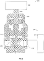
fluid valve 100 is provided inFIG. 1 . In operation, a control pressure or fluid (e.g., air) is provided in apressure chamber 102 via aninput port 104. The control fluid imparts a force to a piston oractuator 106 to move thepiston 106 toward abiasing element 108. In turn, avalve plug 110 coupled to thepiston 106 moves away from avalve seat 112 to a fully open or maximum flow rate position to allow fluid flow through apassageway 114 between aninlet 116 and anoutlet 118. When the control fluid is vented or removed from thepressure chamber 102, thebiasing element 108 moves thepiston 106 toward thepressure chamber 102 to cause thevalve plug 110 to engage thevalve seat 112 to restrict or prevent fluid flow through the passageway 114 (e.g., a closed position). Thus, thefluid valve 100 ofFIG. 1 provides on/off fluid flow control. - To provide precise or accurate fluid flow control, some known control valves employ an electric actuator or motor. For example,
FIG. 2 illustrates anexample fluid valve 200 implemented with anelectric actuator 202. Theelectric actuator 202 is operatively coupled to apiston 204 via astem 206 and thepiston 204 is coupled to avalve plug 208 via astem 210. During operation, theelectric actuator 202 moves thepiston 204 and, thus, thevalve plug 208 relative to avalve seat 212 between a fully open position, a fully closed position and/or any intermediate positions between the fully open position and the fully closed position. However, during a fail condition (e.g., when electric power is not provided to the electric actuator 202), thevalve plug 208 remains in the last control position. For example, during a fail condition, thefluid valve 200 may remain in the open position or an intermediate position between the fully closed position and the fully open position. To provide a fail-safe condition, thevalve 200 employs a fail-safe system 214. The fail-safe system 214 typically includes asecondary valve 216 disposed upstream from aninlet 218 of thefluid valve 200 to prevent fluid flow to thefluid valve 200 during a fail condition. However, such example fail-safe systems 214 increase costs (e.g., manufacturing and installation costs), complexity and provides a relatively larger dimensional envelope. -
FIG. 3 illustrates anexample control valve 300 that includes a flow control assembly or actuator connector assembly 302 implemented with a fail-safe system 304 in accordance with the teachings of this disclosure. Thecontrol valve 300 ofFIG. 3 includes an electric flow controller orelectric actuator 306 operatively coupled to afluid valve 308 via abonnet 310. Thefluid valve 308 includes avalve body 312 that defines afluid flow passageway 314 between aninlet 316 and anoutlet 318. A flow control member 320 (e.g., a valve plug or poppet) is disposed within thefluid flow passageway 314 and includes aseating surface 322. Theflow control member 320 moves relative to avalve seat 324 between a fullyopen position 326, a fully closed position and/or an intermediate position between the fully closed and the fully open positions (as shown inFIG. 3 ) to control fluid flow through a port area ororifice 328 defined between theinlet 316 and theoutlet 318. - The
electric actuator 306 of the illustrated example is operatively coupled to theflow control member 320 via a drive shaft orstem 330. Theelectric actuator 306 of the illustrated example includes amotor 332 that drives thestem 330 via a drive system ordrive train 334. Themotor 332 may be any motor such as, for example, an alternating current (AC) motor, a direct current (DC) motor, a variable frequency motor, a stepper motor, a servo motor, or any other suitable motor or drive member. Thedrive system 334 may include a plurality of gears (e.g. spur gears), a planetary gear system, or any other suitable gear and/or transmission to convert rotational motion of themotor 332 to rectilinear motion of thestem 330. - In the illustrated example, the actuator connector assembly 302 operatively and/or selectively couples the electric actuator 306 (e.g., the stem 330) and the
flow control member 320. As shown inFIG. 3 , the actuator connector assembly 302 is disposed in acavity 336 of thebonnet 310. The example actuator connector assembly 302 ofFIG. 3 includes a piston assembly 340. In particular, the piston assembly 340 of the illustrated example includes a first portion orpiston 342 movably and/or slidably coupled to a second portion orpiston 344. In particular, thefirst piston 342 may be operatively and/or selectively coupled to thesecond piston 344 to prevent movement of thesecond piston 344 relative to thefirst piston 342. To operatively and/or selectively couple the first andsecond pistons fluid chamber 346 is formed or provided between the first andsecond pistons fluid chamber 346 between the first andsecond pistons second piston 344 slides relative to thefirst piston 342. Thefirst piston 342 includes afirst seal 348a (e.g., an O-ring) and thesecond piston 344 includes asecond seal 348b (e.g., an O-ring) to provide a tight seal between thefluid chamber 346 and thecavity 336 of thebonnet 310. Thebonnet 310 of the illustrated example includes afluid port 350 in fluid communication with thefluid chamber 346. In particular, acentral axis 350a of thefluid port 350 is substantially perpendicular to a longitudinal orcentral axis 352 of thefirst piston 342 and/or thesecond piston 344. In other examples, thefluid port 350 can be at a non-perpendicular angle relative to thelongitudinal axis 352 and/or any other position or orientation. Thefluid port 350 and anopening 350b in thebonnet 310 provide a fluid flow path to thefluid chamber 346. - The
first piston 342 of the illustrated example includes an opening or bore 354 formed in a first surface or face 356 of thefirst piston 342 and astem 358 protruding from a second surface or face 360 of thefirst piston 342. In the illustrated example, thefirst surface 356 is opposite thesecond surface 360. More specifically, thefirst surface 356 of thefirst piston 342 is oriented in a direction to face thestem 330 and thesecond surface 360 of thefirst piston 342 is in fluid communication with thefluid chamber 346. Theopening 354 of thefirst piston 342 receives or couples thestem 330 of theelectric actuator 306 and the piston assembly 340. As shown inFIG. 3 , the opening 354 forms a shoulder, flange orprotrusion 362 to engage (e.g., frictionally engage) a flanged or steppedportion 364 of thestem 330. In particular, theshoulder 362 of theopening 354 extends along a portion of a perimeter of theopening 354. Further, theflanged portion 364 and/or an annular groove orchannel 368 may extend along a portion of a perimeter of thestem 330. To enable coupling of thestem 330 and theopening 354 of thefirst piston 342, thefirst surface 356 of thefirst piston 342 includes a slot or keyed opening 366 to enable theflanged portion 364 of thestem 330 to be disposed in theopening 354 without interference from theshoulder 362. - The
stem 330 includes the groove orannular channel 368 to receive theshoulder 362 of theopening 354 to couple thestem 330 and thefirst piston 342. In other words, theannular groove 368 captures theshoulder 362 of theopening 354 with a relatively tight fit connection to reduce or eliminate axial play between thefirst piston 342 and thestem 330 in a direction along theaxis 352. In other examples, thestem 330 may be coupled to thefirst piston 342 via threads, fasteners, pins and/or any other suitable fastening mechanism(s). During assembly, thestem 330 may first be placed in thekeyed opening 366 and slid in a direction substantially perpendicular to theaxis 352 of thefirst piston 342 until theshoulder 362 engages theannular groove 368. - The
second piston 344 of the illustrated example includes an opening or bore 370 formed in a first surface or face 372 of thesecond piston 344 and astem 374 protruding from a second surface or face 376 of thesecond piston 344. In the illustrated example, thefirst surface 372 of thesecond piston 344 is opposite thesecond surface 376 such that thefirst surface 372 of thesecond piston 344 is in fluid communication with thefluid chamber 346 and thesecond surface 376 of thesecond piston 344 is oriented in a direction to face theflow control member 320. Thestem 358 of thefirst piston 342 is coupled to thesecond piston 344 via theopening 370. In particular, thestem 358 of thefirst piston 342 includes a flange, lip or protrudingmember 378 to engage a lip orshoulder 380 formed in theopening 370 of thesecond piston 344 when thefirst piston 342 is coupled to thesecond piston 344. Thefirst surface 372 of thesecond piston 344 includes a slot or keyed opening 382 to enable theflange 378 of thestem 358 of thefirst piston 342 to be disposed in theopening 370 of thesecond piston 344 without interference from theshoulder 380 of theopening 370. The slot or keyedopening 382 may extend along a portion of thefirst surface 372 and/or the shoulder may extend along a portion of a circumference of theopening 370. - The
stem 358 of thefirst piston 342 includes a groove or annular channel 384 (e.g., an elongated groove or channel) to receive or slidably engage theshoulder 380 of theopening 370 of thesecond piston 344. In particular, theshoulder 380 of theopening 370 of thesecond piston 344 moves along theannular channel 384 to enable movement of thesecond piston 344 relative to thefirst piston 342 in a direction parallel to theaxis 352 when thesecond piston 344 is operatively decoupled from thefirst piston 342 as described in greater detail below. In the illustrated example, a length or height of theannular channel 384 and/or a depth of theopening 370 of thesecond piston 344 are at least equal to a full stroke length of theelectric actuator 306 to enable thesecond piston 344 to move relative to thefirst piston 342 from a fully open position to a fully closed position when thesecond piston 344 is operatively decoupled from thefirst piston 342. - The
stem 374 of thesecond piston 344 is coupled (e.g., threadably coupled) to theflow control member 320. Thus, as shown inFIG. 3 , thefirst piston 342 is coupled to theelectric actuator 306 via thestem 330 and thesecond piston 344 is coupled to theflow control member 320 via astem 386. The actuator connector assembly 302 includes a biasingelement 388 to move thesecond piston 344 independently relative to thefirst piston 342 when thefirst piston 342 is operatively decoupled from the second piston 344 (e.g., during a fail condition). The biasingelement 388 is disposed between thesecond surface 376 of thesecond piston 344 and a spring seat 390 (e.g., a valve guide or insert). The biasingelement 388 biases thesecond piston 344 toward thefirst piston 342, but does not interfere with the operation of theelectric actuator 306 when thefirst piston 342 is operatively coupled to thesecond piston 344. - In other words, when the
fluid chamber 346 receives pressurized control fluid, a force imparted to theface 376 of thesecond piston 344 by the biasingelement 388 is less than a force provided by the control fluid to thefirst face 372 of thesecond piston 344 and, thus, is not sufficient to overcome the force imparted to theface 372 of thesecond piston 344 by the control fluid. As a result, thesecond piston 344 does not move relative to thefirst piston 342. As a result, when theelectric actuator 306 overcomes the force provided by the biasingelement 388, themotor 332 can cause (e.g., pull) the first andsecond pistons - To operatively and/or selectively couple the
first piston 342 and thesecond piston 344, a control fluid (e.g., pressurized air, hydraulic oil, etc.) is provided in thefluid chamber 346 via thefluid port 350 and theopening 350b. The pressurized control fluid imparts a force to thesecond surface 360 of thefirst piston 342 and a force to thefirst surface 372 of the second piston 344 (e.g., opposing perpendicular or vertical forces in a direction along the axis 352). In particular, the force imparted by the control fluid causes thefirst piston 342 to move in a direction opposite thesecond piston 344. As shown inFIG. 3 , the control fluid causes thefirst piston 342 to move in a direction toward theelectric actuator 306 and thesecond piston 344 to move in direction toward theflow control member 320 in the orientation ofFIG. 3 . As a result, the pressurized control fluid causes theflange 378 of thestem 358 to frictionally engage theshoulder 380 of theopening 370. In this manner, the pressurized control fluid effectively provides a mechanical linkage, frictional coupling and/or connection to couple the first andsecond pistons flange 378 of thefirst piston 342 to frictionally engage theshoulder 380 of thesecond piston 344 to operatively and/or selectively couple the first andsecond pistons - Further, in the illustrated example, the
second surface 360 of thefirst piston 342 has a surface area that is substantially similar or equal to a surface area of thefirst surface 372 of thesecond piston 344 such that the control fluid provides a substantially equal force to the first andsecond pistons first piston 342 may be different than the surface area of thesecond piston 344 to enable the control fluid to apply a force to thefirst piston 342 that is different than a force provided to thesecond piston 344. -
FIG. 3 illustrates thecontrol valve 300 in the fullyopen position 326 during a non-fail condition or normal operation. A non-fail condition is provided when electric power to theelectric actuator 306 is not interrupted. InFIG. 3 , theelectric actuator 306 is positioned at a partiallyopen stroke position 392 to allow fluid flow through thepassageway 314 between theinlet 316 and theoutlet 318. Theshaft 330 of theelectric actuator 306 includes a shoulder, ledge ortravel limit 394 to limit rectilinear travel of thestem 330 in a direction of theaxis 352 when thestem 330 moves toward thevalve seat 324. In other words, thetravel limit 394 limits and/or defines a fully open stroke position of theelectric actuator 306 when theshoulder 394 of thestem 330 engages asurface 396 of the bonnet 310 (e.g., as shown inFIG. 5 ). -
FIG. 4 illustrates thecontrol valve 300 in a fullyclosed position 400 during the non-fail condition. InFIG. 4 , theelectric actuator 306 is positioned at a fully closedstroke position 402 to prevent fluid flow through thepassageway 314 between theinlet 316 and theoutlet 318. InFIG. 4 , thefluid chamber 346 is provided with the control fluid, which couples the first andsecond pistons - In operation, referring to
FIGS. 3 and4 , thefluid chamber 346 is energized (e.g., provided with a pressurized control fluid) to operatively and/or selectively couple the first andsecond pistons fluid chamber 346, thesecond piston 344 moves together with thefirst piston 342 when theelectric actuator 306 moves between a fully open stroke position, the partiallyopen stroke position 392 ofFIG. 3 , and the fully closedstroke position 402 ofFIG. 4 because the control fluid causes theflange 378 of thefirst piston 342 to frictionally engage theshoulder 380 of thesecond piston 344 with a force in a direction generally parallel to theaxis 352. In other words, during non-fail conditions and/or when a control fluid is otherwise provided to thefluid chamber 346, movement of thesecond piston 344 is dependent on the movement of thefirst piston 342 such that thefirst piston 342 and thesecond piston 344 move together as a unitary piston when theelectric actuator 306 is actuated. As a result, when thefluid chamber 346 is energized, theflange 378 of thestem 358 remains engaged with theshoulder 380 of theopening 370 as theelectric actuator 306 moves between the open stroke position (e.g., a fully open stroke position) to move theflow control member 320 away from thevalve seat 324 to allow fluid flow through thepassageway 314 and the closed stroke position 402 (e.g., a fully closed stroke position) to move theflow control member 320 toward thevalve seat 324 to restrict or prevent fluid flow through thepassageway 314. In other words, when thefluid chamber 346 is energized, thesecond piston 344 does not move relative to or independent from thefirst piston 342. The control fluid provides a pressure or force to operatively and/or selectively couple thefirst piston 342 and thesecond piston 344 such that movement of thefirst piston 342 via theelectric actuator 306 causes theflow control member 320 to move via thesecond piston 344. - As noted above, the
example control valve 100 ofFIGS. 3 and4 includes the fail-safe system 304. The fail-safe system 304 provides protection to a process control system by causing theflow control member 320 to move to a desired position (e.g., a closed position) during emergency situations (e.g., if electric power to the electric actuator fails). In this example, the fail-safe system 304 is an air-based fail-safe system. -
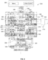
FIG. 5 illustrates thecontrol valve 300 in aclosed position 500 when the fail-safe system 304 is activated during a fail condition. A fail condition may occur when electric power is not provided (e.g., is interrupted) to theelectric actuator 306. InFIG. 5 , theelectric actuator 306 is positioned at a fullyopen stroke position 502. However, theflow control member 320 is engaged (e.g., sealingly engaged) with thevalve seat 324 to restrict or prevent fluid flow through thepassageway 314. - More specifically, in
FIG. 5 , thefirst piston 342 is operatively decoupled from thesecond piston 344. In particular, the control fluid is vented or removed from thefluid chamber 346, causing the mechanical linkage between thefirst piston 342, thesecond piston 344 and the biasingelement 388 to decouple. In other words, the force provided to the first andsecond pistons biasing element 388 to provide a biasing force to theface 376 that is greater than a force provided to theface 372. When operatively decoupled, thesecond piston 344 can move relative to and independent from thefirst piston 342. In particular, thesecond piston 344 can move relative to the first piston 342 a distance defined by an upper surface 504 of theflange 378 of thestem 358 and thesecond surface 360 of the first piston 342 (e.g., a distance defined by a height of the annular channel 384). More specifically, the distance is sufficient to enable thetravel limit 394 defined by thestem 330 to engage theupper surface 396 of thebonnet 310 and enable theflow control member 320 to sealingly engage thevalve seat 324. Thus, regardless of the position of theelectric actuator 306, thesecond piston 344 is at a zero stroke position 506 (e.g., initial position) to cause theflow control member 320 to engage thevalve seat 324. The biasingelement 388 biases thesecond piston 344 and, thus, theflow control member 320 to theclosed position 500. Thus, during a fail condition and/or when the control fluid is removed from thefluid chamber 346, theelectric actuator 306 is decoupled from theflow control member 320 and the biasingelement 388 moves theflow control member 320 into engagement with thevalve seat 324. - To operatively decouple the first and
second pistons fluid chamber 346 is vented. For example, as shown, thecontrol valve 300 may employ a three-way solenoid valve 508 having afirst port 510 to receive the control fluid from a control fluid source, asecond port 512 to provide the control fluid to thefluid chamber 346, and athird port 514 to vent thefluid chamber 346. During a fail condition, electric power to thesolenoid valve 508 is interrupted or removed, thereby causing thesolenoid valve 508 to vent the control fluid from thefluid chamber 346 via thethird port 514 as shown inFIG. 5 . - Thus, a force provided by the control fluid is removed from the
fluid chamber 346 to operatively decouple the first andsecond pistons electric actuator 306 and/or thesolenoid valve 508. When the first andsecond pistons shoulder 380 of theopening 370 moves away from theflange 378 of thestem 358 and thesecond piston 344 slides along thestem 358 via theopening 370. As a result, thesecond piston 344 moves or slides independent from thefirst piston 342 during the fail condition. - For example,
FIG. 6 illustrates thecontrol valve 300 in theclosed position 500 when the control fluid is removed or vented from thefluid chamber 346 and theelectric actuator 306 is positioned at a partiallyopen stroke position 602. Although theelectric actuator 306 is in the partiallyopen stroke position 602, thecontrol valve 300 remains in theclosed position 500 because thefirst piston 342 is operatively decoupled from thesecond piston 344 and, thus, theelectric actuator 306 does not affect the position of theflow control member 320 relative to thevalve seat 324. - The
example control valve 300 ofFIGS. 3-6 is a fail-to-close valve (e.g., push-to-open). In other examples, thecontrol valve 300 may be a fail-to-open valve (e.g., a push-to-close) valve such that in the fail condition, the fail-safe system 304 moves the valve to an open position (e.g., a fully open position). - Although certain example methods, apparatus and articles of manufacture have been described herein, the scope of coverage of this patent is not limited thereto. On the contrary, this patent covers all methods, apparatus and articles of manufacture falling within the scope of the appended claims.
Claims (13)
- A control valve (300) comprising:an electric controller (306) having a drive stem (330);a flow control member (320);a piston assembly (340) positioned in a bonnet (310) of a fluid valve (308), the piston assembly (340) to selectively couple said electric controller (306) and the flow control member (320) to control fluid flow through the fluid valve (308) when electric power is provided to the electric controller (306), the piston assembly (340) to operatively decouple the electric controller (306) and the flow control member (320) when electric power is not provided to the electric controller (306), the piston assembly comprising:a first piston (342);a first opening (354) formed in a first surface (356) of the first piston (342), the first opening (354) is adapted to couple the first piston to the drive stem (330) of the electric flow controller (306);a second piston (344) slidably coupled to the first piston (342), the first piston (342) and the second piston (344) to move together as a unitary piston when electric power is provided to the electric controller (306) and the second piston (344) is to move relative to the first piston (342) when electric power is not provided to the electric controller (306); anda fluid chamber (346) formed between the first piston and the second piston, wherein the fluid chamber (346) receives a control fluid to operatively couple the first and second pistons (342, 344) when electric power is provided to the electric controller (306), the control fluid being removable from the chamber (346) to operatively decouple the first and second pistons (342, 344) to enable the second piston (344) to move relative to the first piston (342) when electric power is not provided to the electric controller (306); characterized in that a first stem (358) protrudes from a second surface (360) of the first piston, the second surface being opposite the first surface of the first piston; and in that the second piston (344) is slidably coupled to the first piston (342) via the first stem.
- The control valve of claim 1, wherein:the control fluid to operatively couple the first and second pistons (342, 344) when the control fluid is provided in the fluid chamber (346); andthe first piston (342) operatively decoupled from the second piston (344) when at least some of the control fluid is removed from the fluid chamber (346).
- The control valve of any preceding claim, wherein the first opening (354) has a first shoulder (362) to engage a first flanged portion (364) of the drive stem (330).
- The control valve of any preceding claim, wherein the second piston (344) comprises a second opening (370) formed in a third surface (372) of the second piston (344).
- The control valve of claim 4, further comprising a second stem (374) protruding from a fourth surface (376) of the second piston (344), the third surface (372) being opposite the fourth surface (376).
- The control valve of claims 4 or 5, wherein the fluid chamber (346) is formed between the second and third surfaces (360, 372) of the respective first and second pistons (342, 344).
- The control valve of any of claims 4 to 6, wherein the first stem (358) of the first piston (342) is coupled to the second piston (344) via the second opening (370).
- The control valve of any of claims 4 to 7, wherein the first stem (358) of the first piston (342) includes a second flanged portion (378) to engage a second shoulder (380) formed in the second opening (370) of the second piston (344) when the first piston (342) is coupled to the second piston (344).
- The control valve of any of claims 1 to 8, wherein the flow control member (320) is coupled to the second piston (344), and wherein the first piston (342) is coupled to said electric flow controller (306).
- The control valve of any of claims 2 to 9, further comprising a biasing element (388) to move the second piston (344) independently from the first piston (342) when at least some of the control fluid is removed from the chamber (346).
- The control valve of any of claims 2 to 10, further comprising a fluid port in fluid communication with the chamber (346).
- The control valve of claim 11, wherein the fluid port (350) comprises an axis (350a) that is substantially perpendicular to a longitudinal axis (352) of the first piston (342).
- The control valve of claims 11 or 12, wherein the fluid port (350) is formed in the bonnet (310).
Applications Claiming Priority (2)
| Application Number | Priority Date | Filing Date | Title |
|---|---|---|---|
| US201161581492P | 2011-12-29 | 2011-12-29 | |
| PCT/US2012/071870 WO2013106202A1 (en) | 2011-12-29 | 2012-12-27 | Fail-safe apparatus for use with fluid valves |
Publications (2)
| Publication Number | Publication Date |
|---|---|
| EP2798252A1 EP2798252A1 (en) | 2014-11-05 |
| EP2798252B1 true EP2798252B1 (en) | 2019-02-20 |
Family
ID=47521191
Family Applications (1)
| Application Number | Title | Priority Date | Filing Date |
|---|---|---|---|
| EP12812806.3A Active EP2798252B1 (en) | 2011-12-29 | 2012-12-27 | Fail-safe apparatus for use with fluid valves |
Country Status (10)
| Country | Link |
|---|---|
| US (1) | US9151401B2 (en) |
| EP (1) | EP2798252B1 (en) |
| JP (1) | JP2015503720A (en) |
| CN (2) | CN203099040U (en) |
| AR (1) | AR089480A1 (en) |
| AU (1) | AU2012364686B2 (en) |
| BR (1) | BR112014016128A8 (en) |
| CA (1) | CA2860233A1 (en) |
| RU (1) | RU2608667C2 (en) |
| WO (1) | WO2013106202A1 (en) |
Families Citing this family (10)
| Publication number | Priority date | Publication date | Assignee | Title |
|---|---|---|---|---|
| US8985137B2 (en) * | 2011-12-29 | 2015-03-24 | Tescom Corporation | Mounting assemblies for use with fluid control devices |
| US9151401B2 (en) * | 2011-12-29 | 2015-10-06 | Tescom Corporation | Fail-safe apparatus for use with fluid valves |
| DE102013021317A1 (en) * | 2013-12-16 | 2015-06-18 | Hydac Filtertechnik Gmbh | Hydraulic valve device |
| CN103925404B (en) * | 2014-05-07 | 2016-02-24 | 西安交通大学 | A kind of actuating motor directly drives the piston type pneumatic proportional pressure-reducing valve of end cam |
| FR3051830B1 (en) * | 2016-05-30 | 2019-12-27 | Safran Aircraft Engines | DEVICE FOR ACTUATING A MOBILE ELEMENT OF A TURBOMACHINE |
| US20180319514A1 (en) * | 2017-05-04 | 2018-11-08 | Eaton Intelligent Power Limited | Fluid coupler |
| EP3492787B1 (en) * | 2017-11-29 | 2022-03-16 | Eugen Seitz AG | Valve unit |
| US11333254B2 (en) | 2018-12-07 | 2022-05-17 | Tescom Corporation | Control valves |
| CN110185834B (en) * | 2019-06-17 | 2022-02-01 | 中国石油大学(华东) | Pressure balance type underwater full-electric Christmas tree valve actuator |
| JP7429778B2 (en) * | 2019-12-19 | 2024-02-08 | サン-ゴバン パフォーマンス プラスティックス コーポレイション | Assemblies and methods of assembling and using them |
Citations (2)
| Publication number | Priority date | Publication date | Assignee | Title |
|---|---|---|---|---|
| JPS63180704A (en) * | 1987-01-21 | 1988-07-25 | Natl Space Dev Agency Japan<Nasda> | Multistage opening valve |
| JP2004251233A (en) * | 2003-02-21 | 2004-09-09 | Sanwa Seiki Co Ltd | Egr valve |
Family Cites Families (17)
| Publication number | Priority date | Publication date | Assignee | Title |
|---|---|---|---|---|
| GB708582A (en) | 1951-04-14 | 1954-05-05 | Inv S Aeronautiques Et Mechani | Improvements in or relating to fluid operated jacks |
| FR2479942A1 (en) * | 1980-04-02 | 1981-10-09 | Electricite De France | INSULATION DEVICE WITH TAREE SAFETY VALVE |
| US4895341A (en) * | 1988-09-30 | 1990-01-23 | Whitey Co. | Pinch valve |
| JP3139343B2 (en) * | 1995-09-19 | 2001-02-26 | 三菱自動車工業株式会社 | Multi-stage opening valve device |
| JP3745427B2 (en) * | 1995-11-14 | 2006-02-15 | Smc株式会社 | Slow exhaust valve for vacuum pressure control |
| AU708610B2 (en) * | 1995-12-20 | 1999-08-05 | Tuchenhagen Gmbh | Actuating device for double seat valves |
| JP3618286B2 (en) * | 2000-09-07 | 2005-02-09 | Smc株式会社 | Smooth exhaust valve |
| ITMI20010872A1 (en) * | 2001-04-26 | 2002-10-26 | Salvagnini Italia Spa | SINGLE CHAMBER SELF-LOCKING CYLINDER |
| US6691980B2 (en) * | 2002-07-05 | 2004-02-17 | Tescom Corporation | Balanced valve with actuator |
| JP3890561B2 (en) * | 2002-07-12 | 2007-03-07 | Smc株式会社 | 2-port vacuum valve with adjustable valve opening |
| US6923212B2 (en) | 2003-01-03 | 2005-08-02 | Control Components, Inc. | Fail safe apparatus for a direct-drive servovalve |
| JP4055002B2 (en) | 2003-09-02 | 2008-03-05 | Smc株式会社 | Vacuum pressure control valve |
| WO2009005916A2 (en) * | 2007-06-15 | 2009-01-08 | Tescom Corporation | 3-way high-pressure air operated valve |
| RU2428614C2 (en) * | 2009-10-29 | 2011-09-10 | Андрей Юрьевич Беляев | Valve switching device (versions) |
| DE102010011516A1 (en) | 2010-03-15 | 2011-09-15 | Robert Bosch Gmbh | Drive with emergency closing function |
| US9151401B2 (en) * | 2011-12-29 | 2015-10-06 | Tescom Corporation | Fail-safe apparatus for use with fluid valves |
| US8985137B2 (en) * | 2011-12-29 | 2015-03-24 | Tescom Corporation | Mounting assemblies for use with fluid control devices |
-
2012
- 2012-12-18 US US13/718,664 patent/US9151401B2/en active Active
- 2012-12-21 CN CN2012207570290U patent/CN203099040U/en not_active Withdrawn - After Issue
- 2012-12-21 CN CN201210599050.7A patent/CN103185168B/en active Active
- 2012-12-27 RU RU2014130997A patent/RU2608667C2/en active
- 2012-12-27 CA CA2860233A patent/CA2860233A1/en not_active Abandoned
- 2012-12-27 BR BR112014016128A patent/BR112014016128A8/en not_active IP Right Cessation
- 2012-12-27 AR ARP120105000A patent/AR089480A1/en not_active Application Discontinuation
- 2012-12-27 AU AU2012364686A patent/AU2012364686B2/en not_active Ceased
- 2012-12-27 JP JP2014550472A patent/JP2015503720A/en active Pending
- 2012-12-27 EP EP12812806.3A patent/EP2798252B1/en active Active
- 2012-12-27 WO PCT/US2012/071870 patent/WO2013106202A1/en not_active Ceased
Patent Citations (2)
| Publication number | Priority date | Publication date | Assignee | Title |
|---|---|---|---|---|
| JPS63180704A (en) * | 1987-01-21 | 1988-07-25 | Natl Space Dev Agency Japan<Nasda> | Multistage opening valve |
| JP2004251233A (en) * | 2003-02-21 | 2004-09-09 | Sanwa Seiki Co Ltd | Egr valve |
Also Published As
| Publication number | Publication date |
|---|---|
| US20130168580A1 (en) | 2013-07-04 |
| RU2608667C2 (en) | 2017-01-23 |
| CA2860233A1 (en) | 2013-07-18 |
| US9151401B2 (en) | 2015-10-06 |
| JP2015503720A (en) | 2015-02-02 |
| RU2014130997A (en) | 2016-02-20 |
| AU2012364686B2 (en) | 2016-12-22 |
| CN103185168A (en) | 2013-07-03 |
| AR089480A1 (en) | 2014-08-27 |
| CN103185168B (en) | 2017-12-26 |
| BR112014016128A2 (en) | 2017-06-13 |
| EP2798252A1 (en) | 2014-11-05 |
| CN203099040U (en) | 2013-07-31 |
| WO2013106202A1 (en) | 2013-07-18 |
| AU2012364686A1 (en) | 2014-07-17 |
| BR112014016128A8 (en) | 2017-07-04 |
Similar Documents
| Publication | Publication Date | Title |
|---|---|---|
| US9151401B2 (en) | Fail-safe apparatus for use with fluid valves | |
| CN103238016B (en) | Stepper motor operated balanced flow control valve | |
| EP2394082B1 (en) | Manual override apparatus for linear actuators | |
| EP2391842B1 (en) | Actuator having an override apparatus | |
| US9457986B2 (en) | Control device for a hydraulic elevator drive | |
| EP3129660B1 (en) | Servo valve | |
| AU2012362670B2 (en) | Mounting assemblies for use with fluid control devices | |
| EP3612756B1 (en) | Electro-pneumatic converters and related methods | |
| JP2015224649A (en) | Two-stage pilot solenoid valve | |
| CN205155188U (en) | Sliding door regulator | |
| US20130037148A1 (en) | Fluid valves having multiple fluid flow control members | |
| KR20240110895A (en) | Electromagnetic valve and air conditioning system equipped with the same | |
| US20120112104A1 (en) | Actuator for controlling a fluid flow | |
| EP2807413B1 (en) | Force multiplying solenoid valve | |
| CN221348123U (en) | Valve driving actuator | |
| CN110925255A (en) | A proportional flow valve | |
| HK1185136B (en) | Stepper motor operated balanced flow control valve | |
| HK1146420A1 (en) | Piloted poppet valve | |
| HK1146420B (en) | Piloted poppet valve |
Legal Events
| Date | Code | Title | Description |
|---|---|---|---|
| PUAI | Public reference made under article 153(3) epc to a published international application that has entered the european phase |
Free format text: ORIGINAL CODE: 0009012 |
|
| 17P | Request for examination filed |
Effective date: 20140725 |
|
| AK | Designated contracting states |
Kind code of ref document: A1 Designated state(s): AL AT BE BG CH CY CZ DE DK EE ES FI FR GB GR HR HU IE IS IT LI LT LU LV MC MK MT NL NO PL PT RO RS SE SI SK SM TR |
|
| DAX | Request for extension of the european patent (deleted) | ||
| 17Q | First examination report despatched |
Effective date: 20160606 |
|
| STAA | Information on the status of an ep patent application or granted ep patent |
Free format text: STATUS: EXAMINATION IS IN PROGRESS |
|
| GRAP | Despatch of communication of intention to grant a patent |
Free format text: ORIGINAL CODE: EPIDOSNIGR1 |
|
| STAA | Information on the status of an ep patent application or granted ep patent |
Free format text: STATUS: GRANT OF PATENT IS INTENDED |
|
| INTG | Intention to grant announced |
Effective date: 20180807 |
|
| GRAS | Grant fee paid |
Free format text: ORIGINAL CODE: EPIDOSNIGR3 |
|
| GRAA | (expected) grant |
Free format text: ORIGINAL CODE: 0009210 |
|
| STAA | Information on the status of an ep patent application or granted ep patent |
Free format text: STATUS: THE PATENT HAS BEEN GRANTED |
|
| AK | Designated contracting states |
Kind code of ref document: B1 Designated state(s): AL AT BE BG CH CY CZ DE DK EE ES FI FR GB GR HR HU IE IS IT LI LT LU LV MC MK MT NL NO PL PT RO RS SE SI SK SM TR |
|
| REG | Reference to a national code |
Ref country code: GB Ref legal event code: FG4D |
|
| REG | Reference to a national code |
Ref country code: CH Ref legal event code: EP |
|
| REG | Reference to a national code |
Ref country code: DE Ref legal event code: R096 Ref document number: 602012056885 Country of ref document: DE |
|
| REG | Reference to a national code |
Ref country code: AT Ref legal event code: REF Ref document number: 1098629 Country of ref document: AT Kind code of ref document: T Effective date: 20190315 |
|
| REG | Reference to a national code |
Ref country code: IE Ref legal event code: FG4D |
|
| REG | Reference to a national code |
Ref country code: NL Ref legal event code: MP Effective date: 20190220 |
|
| REG | Reference to a national code |
Ref country code: LT Ref legal event code: MG4D |
|
| PG25 | Lapsed in a contracting state [announced via postgrant information from national office to epo] |
Ref country code: NO Free format text: LAPSE BECAUSE OF FAILURE TO SUBMIT A TRANSLATION OF THE DESCRIPTION OR TO PAY THE FEE WITHIN THE PRESCRIBED TIME-LIMIT Effective date: 20190520 Ref country code: FI Free format text: LAPSE BECAUSE OF FAILURE TO SUBMIT A TRANSLATION OF THE DESCRIPTION OR TO PAY THE FEE WITHIN THE PRESCRIBED TIME-LIMIT Effective date: 20190220 Ref country code: LT Free format text: LAPSE BECAUSE OF FAILURE TO SUBMIT A TRANSLATION OF THE DESCRIPTION OR TO PAY THE FEE WITHIN THE PRESCRIBED TIME-LIMIT Effective date: 20190220 Ref country code: NL Free format text: LAPSE BECAUSE OF FAILURE TO SUBMIT A TRANSLATION OF THE DESCRIPTION OR TO PAY THE FEE WITHIN THE PRESCRIBED TIME-LIMIT Effective date: 20190220 Ref country code: SE Free format text: LAPSE BECAUSE OF FAILURE TO SUBMIT A TRANSLATION OF THE DESCRIPTION OR TO PAY THE FEE WITHIN THE PRESCRIBED TIME-LIMIT Effective date: 20190220 Ref country code: PT Free format text: LAPSE BECAUSE OF FAILURE TO SUBMIT A TRANSLATION OF THE DESCRIPTION OR TO PAY THE FEE WITHIN THE PRESCRIBED TIME-LIMIT Effective date: 20190620 |
|
| PG25 | Lapsed in a contracting state [announced via postgrant information from national office to epo] |
Ref country code: HR Free format text: LAPSE BECAUSE OF FAILURE TO SUBMIT A TRANSLATION OF THE DESCRIPTION OR TO PAY THE FEE WITHIN THE PRESCRIBED TIME-LIMIT Effective date: 20190220 Ref country code: RS Free format text: LAPSE BECAUSE OF FAILURE TO SUBMIT A TRANSLATION OF THE DESCRIPTION OR TO PAY THE FEE WITHIN THE PRESCRIBED TIME-LIMIT Effective date: 20190220 Ref country code: LV Free format text: LAPSE BECAUSE OF FAILURE TO SUBMIT A TRANSLATION OF THE DESCRIPTION OR TO PAY THE FEE WITHIN THE PRESCRIBED TIME-LIMIT Effective date: 20190220 Ref country code: IS Free format text: LAPSE BECAUSE OF FAILURE TO SUBMIT A TRANSLATION OF THE DESCRIPTION OR TO PAY THE FEE WITHIN THE PRESCRIBED TIME-LIMIT Effective date: 20190620 Ref country code: BG Free format text: LAPSE BECAUSE OF FAILURE TO SUBMIT A TRANSLATION OF THE DESCRIPTION OR TO PAY THE FEE WITHIN THE PRESCRIBED TIME-LIMIT Effective date: 20190520 Ref country code: GR Free format text: LAPSE BECAUSE OF FAILURE TO SUBMIT A TRANSLATION OF THE DESCRIPTION OR TO PAY THE FEE WITHIN THE PRESCRIBED TIME-LIMIT Effective date: 20190521 |
|
| REG | Reference to a national code |
Ref country code: AT Ref legal event code: MK05 Ref document number: 1098629 Country of ref document: AT Kind code of ref document: T Effective date: 20190220 |
|
| PG25 | Lapsed in a contracting state [announced via postgrant information from national office to epo] |
Ref country code: AL Free format text: LAPSE BECAUSE OF FAILURE TO SUBMIT A TRANSLATION OF THE DESCRIPTION OR TO PAY THE FEE WITHIN THE PRESCRIBED TIME-LIMIT Effective date: 20190220 Ref country code: ES Free format text: LAPSE BECAUSE OF FAILURE TO SUBMIT A TRANSLATION OF THE DESCRIPTION OR TO PAY THE FEE WITHIN THE PRESCRIBED TIME-LIMIT Effective date: 20190220 Ref country code: RO Free format text: LAPSE BECAUSE OF FAILURE TO SUBMIT A TRANSLATION OF THE DESCRIPTION OR TO PAY THE FEE WITHIN THE PRESCRIBED TIME-LIMIT Effective date: 20190220 Ref country code: IT Free format text: LAPSE BECAUSE OF FAILURE TO SUBMIT A TRANSLATION OF THE DESCRIPTION OR TO PAY THE FEE WITHIN THE PRESCRIBED TIME-LIMIT Effective date: 20190220 Ref country code: CZ Free format text: LAPSE BECAUSE OF FAILURE TO SUBMIT A TRANSLATION OF THE DESCRIPTION OR TO PAY THE FEE WITHIN THE PRESCRIBED TIME-LIMIT Effective date: 20190220 Ref country code: SK Free format text: LAPSE BECAUSE OF FAILURE TO SUBMIT A TRANSLATION OF THE DESCRIPTION OR TO PAY THE FEE WITHIN THE PRESCRIBED TIME-LIMIT Effective date: 20190220 Ref country code: EE Free format text: LAPSE BECAUSE OF FAILURE TO SUBMIT A TRANSLATION OF THE DESCRIPTION OR TO PAY THE FEE WITHIN THE PRESCRIBED TIME-LIMIT Effective date: 20190220 Ref country code: DK Free format text: LAPSE BECAUSE OF FAILURE TO SUBMIT A TRANSLATION OF THE DESCRIPTION OR TO PAY THE FEE WITHIN THE PRESCRIBED TIME-LIMIT Effective date: 20190220 |
|
| REG | Reference to a national code |
Ref country code: DE Ref legal event code: R097 Ref document number: 602012056885 Country of ref document: DE |
|
| PG25 | Lapsed in a contracting state [announced via postgrant information from national office to epo] |
Ref country code: PL Free format text: LAPSE BECAUSE OF FAILURE TO SUBMIT A TRANSLATION OF THE DESCRIPTION OR TO PAY THE FEE WITHIN THE PRESCRIBED TIME-LIMIT Effective date: 20190220 Ref country code: SM Free format text: LAPSE BECAUSE OF FAILURE TO SUBMIT A TRANSLATION OF THE DESCRIPTION OR TO PAY THE FEE WITHIN THE PRESCRIBED TIME-LIMIT Effective date: 20190220 |
|
| PLBE | No opposition filed within time limit |
Free format text: ORIGINAL CODE: 0009261 |
|
| STAA | Information on the status of an ep patent application or granted ep patent |
Free format text: STATUS: NO OPPOSITION FILED WITHIN TIME LIMIT |
|
| PG25 | Lapsed in a contracting state [announced via postgrant information from national office to epo] |
Ref country code: AT Free format text: LAPSE BECAUSE OF FAILURE TO SUBMIT A TRANSLATION OF THE DESCRIPTION OR TO PAY THE FEE WITHIN THE PRESCRIBED TIME-LIMIT Effective date: 20190220 |
|
| 26N | No opposition filed |
Effective date: 20191121 |
|
| PG25 | Lapsed in a contracting state [announced via postgrant information from national office to epo] |
Ref country code: SI Free format text: LAPSE BECAUSE OF FAILURE TO SUBMIT A TRANSLATION OF THE DESCRIPTION OR TO PAY THE FEE WITHIN THE PRESCRIBED TIME-LIMIT Effective date: 20190220 |
|
| PG25 | Lapsed in a contracting state [announced via postgrant information from national office to epo] |
Ref country code: TR Free format text: LAPSE BECAUSE OF FAILURE TO SUBMIT A TRANSLATION OF THE DESCRIPTION OR TO PAY THE FEE WITHIN THE PRESCRIBED TIME-LIMIT Effective date: 20190220 |
|
| REG | Reference to a national code |
Ref country code: CH Ref legal event code: PL |
|
| REG | Reference to a national code |
Ref country code: BE Ref legal event code: MM Effective date: 20191231 |
|
| PG25 | Lapsed in a contracting state [announced via postgrant information from national office to epo] |
Ref country code: MC Free format text: LAPSE BECAUSE OF FAILURE TO SUBMIT A TRANSLATION OF THE DESCRIPTION OR TO PAY THE FEE WITHIN THE PRESCRIBED TIME-LIMIT Effective date: 20190220 |
|
| GBPC | Gb: european patent ceased through non-payment of renewal fee |
Effective date: 20191227 |
|
| PG25 | Lapsed in a contracting state [announced via postgrant information from national office to epo] |
Ref country code: IE Free format text: LAPSE BECAUSE OF NON-PAYMENT OF DUE FEES Effective date: 20191227 Ref country code: FR Free format text: LAPSE BECAUSE OF NON-PAYMENT OF DUE FEES Effective date: 20191231 Ref country code: GB Free format text: LAPSE BECAUSE OF NON-PAYMENT OF DUE FEES Effective date: 20191227 Ref country code: LU Free format text: LAPSE BECAUSE OF NON-PAYMENT OF DUE FEES Effective date: 20191227 |
|
| PG25 | Lapsed in a contracting state [announced via postgrant information from national office to epo] |
Ref country code: BE Free format text: LAPSE BECAUSE OF NON-PAYMENT OF DUE FEES Effective date: 20191231 Ref country code: CH Free format text: LAPSE BECAUSE OF NON-PAYMENT OF DUE FEES Effective date: 20191231 Ref country code: LI Free format text: LAPSE BECAUSE OF NON-PAYMENT OF DUE FEES Effective date: 20191231 |
|
| PG25 | Lapsed in a contracting state [announced via postgrant information from national office to epo] |
Ref country code: CY Free format text: LAPSE BECAUSE OF FAILURE TO SUBMIT A TRANSLATION OF THE DESCRIPTION OR TO PAY THE FEE WITHIN THE PRESCRIBED TIME-LIMIT Effective date: 20190220 |
|
| PG25 | Lapsed in a contracting state [announced via postgrant information from national office to epo] |
Ref country code: HU Free format text: LAPSE BECAUSE OF FAILURE TO SUBMIT A TRANSLATION OF THE DESCRIPTION OR TO PAY THE FEE WITHIN THE PRESCRIBED TIME-LIMIT; INVALID AB INITIO Effective date: 20121227 Ref country code: MT Free format text: LAPSE BECAUSE OF FAILURE TO SUBMIT A TRANSLATION OF THE DESCRIPTION OR TO PAY THE FEE WITHIN THE PRESCRIBED TIME-LIMIT Effective date: 20190220 |
|
| PG25 | Lapsed in a contracting state [announced via postgrant information from national office to epo] |
Ref country code: MK Free format text: LAPSE BECAUSE OF FAILURE TO SUBMIT A TRANSLATION OF THE DESCRIPTION OR TO PAY THE FEE WITHIN THE PRESCRIBED TIME-LIMIT Effective date: 20190220 |
|
| P01 | Opt-out of the competence of the unified patent court (upc) registered |
Effective date: 20230526 |
|
| PGFP | Annual fee paid to national office [announced via postgrant information from national office to epo] |
Ref country code: DE Payment date: 20241121 Year of fee payment: 13 |