EP2798210B1 - Kraftstoffhochdruckpumpe für ein kraftstoffeinspritzsystem - Google Patents
Kraftstoffhochdruckpumpe für ein kraftstoffeinspritzsystem Download PDFInfo
- Publication number
- EP2798210B1 EP2798210B1 EP12818522.0A EP12818522A EP2798210B1 EP 2798210 B1 EP2798210 B1 EP 2798210B1 EP 12818522 A EP12818522 A EP 12818522A EP 2798210 B1 EP2798210 B1 EP 2798210B1
- Authority
- EP
- European Patent Office
- Prior art keywords
- seal
- hollow cylinder
- ring
- pressure fuel
- pump piston
- Prior art date
- Legal status (The legal status is an assumption and is not a legal conclusion. Google has not performed a legal analysis and makes no representation as to the accuracy of the status listed.)
- Not-in-force
Links
- 239000000446 fuel Substances 0.000 title claims description 20
- 238000002347 injection Methods 0.000 title claims description 4
- 239000007924 injection Substances 0.000 title claims description 4
- 238000002485 combustion reaction Methods 0.000 claims description 10
- 239000000463 material Substances 0.000 claims description 2
- 239000004033 plastic Substances 0.000 claims description 2
- -1 polytetrafluoroethylene Polymers 0.000 claims description 2
- 229920001343 polytetrafluoroethylene Polymers 0.000 claims description 2
- 239000004810 polytetrafluoroethylene Substances 0.000 claims description 2
- 238000007789 sealing Methods 0.000 description 8
- 238000000034 method Methods 0.000 description 7
- 230000002093 peripheral effect Effects 0.000 description 5
- 238000000926 separation method Methods 0.000 description 4
- 230000010349 pulsation Effects 0.000 description 3
- 238000004088 simulation Methods 0.000 description 2
- 230000006835 compression Effects 0.000 description 1
- 238000007906 compression Methods 0.000 description 1
- 230000007547 defect Effects 0.000 description 1
- 230000001419 dependent effect Effects 0.000 description 1
- 238000011161 development Methods 0.000 description 1
- 230000018109 developmental process Effects 0.000 description 1
- 230000000694 effects Effects 0.000 description 1
- 239000000295 fuel oil Substances 0.000 description 1
- 239000010687 lubricating oil Substances 0.000 description 1
- 239000012528 membrane Substances 0.000 description 1
- 230000035515 penetration Effects 0.000 description 1
Images

Classifications
-
- F—MECHANICAL ENGINEERING; LIGHTING; HEATING; WEAPONS; BLASTING
- F04—POSITIVE - DISPLACEMENT MACHINES FOR LIQUIDS; PUMPS FOR LIQUIDS OR ELASTIC FLUIDS
- F04B—POSITIVE-DISPLACEMENT MACHINES FOR LIQUIDS; PUMPS
- F04B1/00—Multi-cylinder machines or pumps characterised by number or arrangement of cylinders
- F04B1/04—Multi-cylinder machines or pumps characterised by number or arrangement of cylinders having cylinders in star- or fan-arrangement
- F04B1/0404—Details or component parts
- F04B1/0408—Pistons
-
- F—MECHANICAL ENGINEERING; LIGHTING; HEATING; WEAPONS; BLASTING
- F02—COMBUSTION ENGINES; HOT-GAS OR COMBUSTION-PRODUCT ENGINE PLANTS
- F02M—SUPPLYING COMBUSTION ENGINES IN GENERAL WITH COMBUSTIBLE MIXTURES OR CONSTITUENTS THEREOF
- F02M59/00—Pumps specially adapted for fuel-injection and not provided for in groups F02M39/00 -F02M57/00, e.g. rotary cylinder-block type of pumps
- F02M59/02—Pumps specially adapted for fuel-injection and not provided for in groups F02M39/00 -F02M57/00, e.g. rotary cylinder-block type of pumps of reciprocating-piston or reciprocating-cylinder type
- F02M59/10—Pumps specially adapted for fuel-injection and not provided for in groups F02M39/00 -F02M57/00, e.g. rotary cylinder-block type of pumps of reciprocating-piston or reciprocating-cylinder type characterised by the piston-drive
- F02M59/102—Mechanical drive, e.g. tappets or cams
-
- F—MECHANICAL ENGINEERING; LIGHTING; HEATING; WEAPONS; BLASTING
- F02—COMBUSTION ENGINES; HOT-GAS OR COMBUSTION-PRODUCT ENGINE PLANTS
- F02M—SUPPLYING COMBUSTION ENGINES IN GENERAL WITH COMBUSTIBLE MIXTURES OR CONSTITUENTS THEREOF
- F02M59/00—Pumps specially adapted for fuel-injection and not provided for in groups F02M39/00 -F02M57/00, e.g. rotary cylinder-block type of pumps
- F02M59/44—Details, components parts, or accessories not provided for in, or of interest apart from, the apparatus of groups F02M59/02 - F02M59/42; Pumps having transducers, e.g. to measure displacement of pump rack or piston
- F02M59/442—Details, components parts, or accessories not provided for in, or of interest apart from, the apparatus of groups F02M59/02 - F02M59/42; Pumps having transducers, e.g. to measure displacement of pump rack or piston means preventing fuel leakage around pump plunger, e.g. fluid barriers
-
- F—MECHANICAL ENGINEERING; LIGHTING; HEATING; WEAPONS; BLASTING
- F04—POSITIVE - DISPLACEMENT MACHINES FOR LIQUIDS; PUMPS FOR LIQUIDS OR ELASTIC FLUIDS
- F04B—POSITIVE-DISPLACEMENT MACHINES FOR LIQUIDS; PUMPS
- F04B1/00—Multi-cylinder machines or pumps characterised by number or arrangement of cylinders
- F04B1/04—Multi-cylinder machines or pumps characterised by number or arrangement of cylinders having cylinders in star- or fan-arrangement
- F04B1/0404—Details or component parts
- F04B1/0426—Arrangements for pressing the pistons against the actuated cam; Arrangements for connecting the pistons to the actuated cam
-
- F—MECHANICAL ENGINEERING; LIGHTING; HEATING; WEAPONS; BLASTING
- F04—POSITIVE - DISPLACEMENT MACHINES FOR LIQUIDS; PUMPS FOR LIQUIDS OR ELASTIC FLUIDS
- F04B—POSITIVE-DISPLACEMENT MACHINES FOR LIQUIDS; PUMPS
- F04B1/00—Multi-cylinder machines or pumps characterised by number or arrangement of cylinders
- F04B1/04—Multi-cylinder machines or pumps characterised by number or arrangement of cylinders having cylinders in star- or fan-arrangement
- F04B1/0404—Details or component parts
- F04B1/0443—Draining of the housing; Arrangements for handling leaked fluids
Definitions
- the invention relates to a high-pressure fuel pump designed in particular as a plug-in pump for a fuel injection system for injecting fuel into the combustion chamber of an internal combustion engine having the features of the preamble of claim 1.
- a designed as a plug-in pump high pressure pump for an internal combustion engine is, for example, from the published patent application DE 10 2008 002 195 A1 out. It comprises a piston which is accommodated in a hollow cylinder and has one end which projects beyond the hollow cylinder and can be displaced into a reciprocating movement by a compression spring against a radial projection of a drive shaft rotating about an axis in the hollow cylinder.
- the hollow cylinder superior end of the piston and the hollow cylinder are liquid-tightly connected by a bellows and a from Bellows, the hollow cylinder and the pump piston enclosed annular space is connected to a leakage line, the leakage line opens directly into the annulus.
- Bellows seals of the aforementioned type are among the contactless sealing method. They have the disadvantage that a defect leads to the immediate failure of the internal combustion engine.
- the present invention is therefore based on the object, a high-pressure fuel pump, in particular plug-in pump to specify, via which a permanently secure media separation is ensured.
- the proposed high-pressure fuel pump, in particular plug-in pump, for a fuel injection system for injecting fuel into the combustion chamber of an internal combustion engine comprises a liftable pump piston whose first end is guided in a hollow cylinder and whose second end is indirectly supported via a cup-shaped member on a cam or eccentric shaft. Furthermore, the high-pressure pump comprises a preferably designed as a bellows seal, which is attached to form an annular space on the one hand on the pump piston and on the other hand on the hollow cylinder. According to the invention, a guide gap formed between the pump piston and the hollow cylinder is designed as an annular gap seal for sealing the annular space.
- the guide gap opens into an annular groove formed in the hollow cylinder, which is connected to a leakage line for returning a leakage amount.
- both a contactless and a contacting sealing method are used.
- the combination of both sealing methods thus ensures a particularly secure media separation.
- the internal combustion engine can continue to operate, since a seal is still ensured via the annular gap seal.
- a further formed between the pump piston and the hollow cylinder and opening into the annular groove guide gap is designed as an annular gap seal.
- the further guide gap is separated from the first guide gap via the annular groove formed in the hollow cylinder. This ensures that a leakage quantity flowing over the further guide gap into the annular groove is dissipated via the leakage line connected thereto and does not pass into the annular space enclosed by the preferably designed as a bellows seal. In this way, pressure pulsations in the annulus are avoided and consequently the annulus enclosing seal relieved.
- the lengths required for this purpose l 1 and l 2 of the two executed as annular gap seals guide column can be determined by simulation. Preferably, the length l 2 of the further guide gap is greater than the length l 1 of the first guide gap selected.
- the seal which is preferably designed as a bellows, is fastened to an outer peripheral surface of the pump piston. In this way, the volume of the enclosed by the seal annulus is minimized. Further preferably, the attachment of the seal on the pump piston by means of a crimp ring.
- the crimp ring allows a gas-tight connection of the seal to the pump piston. Alternatively or additionally, further fastening means may be provided.
- the seal which is preferably designed as a bellows, is fastened to an outer peripheral surface of the hollow cylinder.
- the fastening takes place again by means of a crimp ring, in order at the same time to effect a gas-tight connection.
- Vorteithaft we the collar is radially inwardly attached to the hollow cylinder and extends the designed as an annular gap seal guide gap between the pump piston and the hollow cylinder.
- the preferably designed as a bellows seal comes to lie in this way close to the pump piston, whereby the volume of the enclosed seal of the annular space on is minimized.
- direct contact of the individual folds of the seal, which is preferably designed as a bellows, with the pump piston should be avoided in order to increase the service life of the seal.
- the length of the preferably designed as a bellows seal is therefore to be chosen such that the opening angle of the individual folds during a stroke of the pump piston is as small as possible.
- the seal is made of a resistant material, in particular of a plastic, such as polytetrafluoroethylene.
- the in the Fig. 1 plug-in pump shown comprises a pump piston 1, whose first end 1.1 received in a hollow cylinder 2 of a cylinder head and the second end 1.2 indirectly via a cup-shaped member 3 is supported on a camshaft 4.
- the second end 1.2 forms a piston foot 17, soften a spring plate 16 is placed for receiving a spring 15.
- the spring force of the spring 15 holds the cup-shaped component 3 and the pump piston 1 in contact with the camshaft 4.
- the spring 15 and the cup-shaped component 3 surround the hollow cylinder. 2
- the pump piston 1 and the hollow cylinder 2 are connected to seal a guide gap 7, 10 via a seal 5 designed as a bellows.
- the seal 5 is fastened on the one hand to an outer circumferential surface 11 of the pump piston 1 and on the other hand to an outer circumferential surface 13 of a collar 14 attached to the hollow cylinder 2.
- the attachment takes place by means of Crimpringe 12, which cause a gas-tight connection of the seal 5 to the pump piston 1 and the hollow cylinder 2.
- the seal 5 designed as a bellows surrounds an annular space 6, in which the guide gap 7 opens.
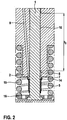
- the guide gap 7 terminates at an annular groove 8 formed in the hollow cylinder 2, which is connected to a leakage line 9 for the return of a leakage amount emerging via the further guide gap 10. This ensures that the leakage quantity does not enter the annular space 6 and causes pressure pulsations which would stress the seal 5.
- the lengths l 1 and l 2 are chosen such that l 1 ⁇ l 2 .
- the optimal lengths, which ensure a sufficient seal for media separation, can be found out by simulation.
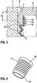
- the section of the Fig. 3 shows the attachment of the bellows formed as a seal 5 on the collar 14 of the hollow cylinder 2 by means of a crimp ring 12.
- At the seal 5 are for receiving the crimp rings 12 at both ends of collar portions 18 are formed (see Fig. 4 ), which allow application of the crimp ring 12.
- the collar portions 18 further allow a flat application of the seal 5 on the outer peripheral surface 11 of the pump piston 1 and the outer peripheral surface 13 of the attached to the hollow cylinder 2 collar 14.
- the position of the collar portions 18 is selected such that the convolutions of the bellows at a distance with respect to the pump piston 1 are held.
- the volume of the annular space 6 is reduced to a minimum, in order to minimize the unwanted circulation volume at the same time.
- seal 5 can also be realized by a differently shaped membrane seal.
Landscapes
- Engineering & Computer Science (AREA)
- Mechanical Engineering (AREA)
- General Engineering & Computer Science (AREA)
- Chemical & Material Sciences (AREA)
- Combustion & Propulsion (AREA)
- Fuel-Injection Apparatus (AREA)
- Reciprocating Pumps (AREA)
Description
- Die Erfindung betrifft eine insbesondere als Steckpumpe ausgestaltete Kraftstoffhochdruckpumpe für ein Kraftstoffeinspritzsystem zum Einspritzen von Kraftstoff in den Brennraum einer Brennkraftmaschine mit den Merkmalen des Oberbegriffs des Anspruchs 1.
- Eine als Steckpumpe ausgeführte Kraftstoffhochdruckpumpe für eine Verbrennungskraftmaschine geht beispielsweise aus der Offenlegungsschrift
DE 10 2008 002 195 A1 hervor. Sie umfasst einen in einem Hohlzylinder aufgenommenen Kolben mit einem Ende, das den Hohlzylinder überragt und durch eine Druckfeder an einen radialen Vorsprung einer um eine Achse rotierenden Antriebswelle in dem Hohlzylinder in eine hin- und hergehende Bewegung versetzbar ist. Zur Trennung der Medien Kraftstoff und Schmieröl, wobei insbesondere das Eindringen von Kraftstoff in den ölbeaufschlagten Innenraum der Verbrennungskraftmaschine verhindert werden soll, wird in dieser Druckschrift vorgeschlagen, das das den Hohlzylinder überragende Ende des Kolbens und der Hohlzylinder durch einen Faltenbalg flüssigkeitsdicht verbunden sind und ein vom Faltenbalg, dem Hohlzylinder und dem Pumpenkolben umschlossener Ringraum an eine Leckageleitung angeschlossen ist, wobei die Leckageleitung unmittelbar in den Ringraum mündet. - Faltenbalg-Dichtungen der vorstehend genannten Art gehören zu den berührlosen Dichtverfahren. Sie weisen den Nachteil auf, dass ein Defekt zum sofortigen Ausfall der Verbrennungskraftmaschine führt.
- Darüber hinaus sind berührende Dichtverfahren, wie beispielsweise Stangendichtungen und metallische Dichtungen bekannt, welche einen leckagebehafteten Ringspalt ausbilden. Mit Verschärfung der Abgasgesetzte ist eine solche Leckage nicht mehr hinnehmbar.
- Ausgehend von dem vorstehend genannten Stand der Technik liegt daher der vorliegenden Erfindung die Aufgabe zugrunde, eine Kraftstoffhochdruckpumpe, insbesondere Steckpumpe, anzugeben, über welche eine dauerhaft sichere Medientrennung gewährleistet ist.
- Die Aufgabe wird gelöst durch eine Kraftstoffhochdruckpumpe mit den Merkmalen des Anspruchs 1. Vorteilhafte Weiterbildungen der Erfindung sind in den Unteransprüchen angegeben.
- Die vorgeschlagene Kraftstoffhochdruckpumpe, insbesondere Steckpumpe, für ein Kraftstoffeinspritzsystem zum Einspritzen von Kraftstoff in den Brennraum einer Brennkraftmaschine umfasst einen hubbeweglichen Pumpenkolben, dessen erstes Ende in einem Hohlzylinder geführt und dessen zweites Ende mittelbar über ein tassenförmiges Bauteil an einer Nocken- oder Exzenterwelle abgestützt ist. Ferner umfasst die Hochdruckpumpe eine vorzugsweise als Faltenbalg ausgebildete Dichtung, welche unter Ausbildung eines Ringraums einerseits am Pumpenkolben und andererseits am Hohlzylinder befestigt ist. Erfindungsgemäß ist zur Abdichtung des Ringraums ein zwischen dem Pumpenkolben und dem Hohlzylinder ausgebildeter Führungsspalt als Ringspaltdichtung ausgeführt. Ferner ist vorgesehen, dass der Führungsspalt in eine im Hohlzylinder ausgebildete Ringnut mündet, welche zur Rückführung einer Leckagemenge an eine Leckageleitung angeschlossen ist. Bei der erfindungsgemäßen Hochdruckpumpe gelangen somit sowohl ein berührloses als auch ein berührendes Dichtverfahren zur Anwendung. Die Kombination beider Dichtverfahren gewährleistet somit eine besonders sichere Medientrennung. Zugleich kann bei Ausfall eines Dichtverfahrens, insbesondere des berührlosen Dichtverfahrens mittels Faltenbalg, die Brennkraftmaschine weiter betrieben werden, da eine Dichtung weiterhin über die Ringspaltdichtung gewährleistet ist. Durch die Kombination zweier Dichtverfahren, kann zudem die Belastung der vorzugsweise als Faltenbalg ausgebildeten Dichtung reduziert werden, so dass weniger oft mit einem Ausfall zu rechnen ist. Denn die Ringspaltdichtung entkoppelt die Leckageleitung von dem Ringraum, der von der vorzugsweise als Faltenbalg ausgebildeten Dichtung umschlossen wird, so dass die Dichtung belastende Druckpulsationen im Ringraum verringert werden.
- Bevorzugt ist ein weiterer zwischen dem Pumpenkolben und dem Hohlzylinder ausgebildeter und in die Ringnut mündender Führungsspalt als Ringspaltdichtung ausgeführt. Der weitere Führungsspalt ist von dem ersten Führungsspalt über die im Hohlzylinder ausgebildete Ringnut getrennt. Dadurch ist sichergestellt, dass eine über den weiteren Führungsspalt in die Ringnut strömende Leckagemenge über die hieran angeschlossene Leckageleitung abgeführt wird und nicht in den von der vorzugsweise als Faltenbalg ausgebildeten Dichtung umschlossenen Ringraum gelangt. Auf diese Weise werden Druckpulsationen im Ringraum vermieden und folglich die den Ringraum umschließende Dichtung entlastet. Die hierzu erforderlichen Längen l1 und l2 der beiden als Ringspaltdichtungen ausgeführten Führungsspalte kann über Simulation bestimmt werden. Vorzugsweise ist die Länge l2 des weiteren Führungsspaltes größer als die Länge l1 des ersten Führungsspaltes gewählt.
- Gemäß einer bevorzugten Ausführungsform der Erfindung ist die vorzugsweise als Faltenbalg ausgeführte Dichtung an einer Außenumfangsfläche des Pumpenkolbens befestigt. Auf diese Weise wird das Volumen des von der Dichtung umschlossenen Ringraums minimiert. Ferner bevorzugt erfolgt die Befestigung der Dichtung am Pumpenkolben mittels eines Crimprings. Der Crimpring ermöglicht eine gasdichte Anbindung der Dichtung an den Pumpenkolben. Alternativ oder ergänzend können weitere Befestigungsmittel vorgesehen sein.
- Des Weiteren wird vorgeschlagen, dass die vorzugsweise als Faltenbalg ausgeführte Dichtung an einer Außenumfangsfläche des Hohlzylinders befestigt ist. Besonders bevorzugt erfolgt die Befestigung wiederum mittels eines Crimprings, um zugleich eine gasdichte Anbindung zu bewirken.
- Gemäß einer Weiterbildung der Erfindung ist die Außenumfangsfläche, an welcher die vorzugsweise als Faltenbalg ausgebildete Dichtung am Hohlzylinder befestigt ist, an einem an den Hohlzylinder angesetzten Kragen ausgebildet. Vorteithafterweise ist der Kragen radial innenliegend an den Hohlzylinder angesetzt und verlängert den als Ringspaltdichtung ausgeführten Führungsspalt zwischen dem Pumpenkolben und dem Hohlzylinder. Die vorzugsweise als Faltenbalg ausgebildete Dichtung kommt auf diese Weise nah am Pumpenkolben zu liegen, wodurch das Volumen des von der Dichtung umschlossenen Ringraums weiter minimiert wird. Einen direkten Kontakt der einzelnen Faltungen der vorzugsweise als Faltenbalg ausgebildeten Dichtung mit dem Pumpenkolben gilt es jedoch zu vermeiden, um die Lebensdauer der Dichtung zu erhöhen. Die Länge der vorzugsweise als Faltenbalg ausgebildeten Dichtung ist daher derart zu wählen, dass der Öffnungswinkel der einzelnen Faltungen während einer Hubbewegung des Pumpenkolbens möglichst klein ist.
- Um die Robustheit und damit die Lebensdauer der vorzugsweise als Faltenbalg ausgebildeten Dichtung zu erhöhen, wird ferner vorgeschlagen, dass die Dichtung aus einem widerstandsfähigen Werkstoff, insbesondere aus einem Kunststoff, wie beispielsweise Polytetrafluorethylen, hergestellt ist.
- Eine bevorzugte Ausführungsform der Erfindung wird nachfolgend anhand der beigefügten Zeichnungen näher erläutert. Diese zeigen:
- Fig. 1
- einen Längsschnitt durch eine als Steckpumpe ausgeführte erfindungsgemäße Kraftstoffhochdruckpumpe,
- Fig. 2
- einen Ausschnitt der
Fig. 1 im Bereich der Führung des Pumpenkolbens, - Fig. 3
- einen Ausschnitt der
Fig. 1 im Bereich der Befestigung der FaltenbalgDichtung am Hohlzylinder und - Fig. 4
- eine perspektivische Darstellung der Faltenbalg-Dichtung.
- Die in der
Fig. 1 dargestellte Steckpumpe umfasst einen Pumpenkolben 1, dessen erstes Ende 1.1 in einem Hohlzylinder 2 eines Zylinderkopfes aufgenommen und dessen zweites Ende 1.2 mittelbar über ein tassenförmiges Bauteil 3 an einer Nockenwelle 4 abgestützt ist. Das zweite Ende 1.2 bildet eine Kolbenfuß 17 aus, aufweichen ein Federteller 16 zur Aufnahme einer Feder 15 aufgelegt ist. Die Federkraft der Feder 15 hält das tassenförmige Bauteil 3 und den Pumpenkolben 1 in Anlage mit der Nockenwelle 4. Die Feder 15 und das tassenförmige Bauteil 3 umgeben den Hohlzylinder 2. - Der Pumpenkolben 1 und der Hohlzylinder 2 sind zur Abdichtung eines Führungsspalts 7, 10 über eine als Faltenbalg ausgebildete Dichtung 5 verbunden.
- Die Dichtung 5 ist einerseits an einer Außenumfangsfläche 11 des Pumpenkolbens 1 und andererseits an einer Außenumfangsfläche 13 eines an den Hohlzylinder 2 angesetzten Kragens 14 befestigt. Die Befestigung erfolgt mittels Crimpringe 12, welche eine gasdichte Anbindung der Dichtung 5 an den Pumpenkolben 1 und den Hohlzylinder 2 bewirken. Die als Faltenbalg ausgebildete Dichtung 5 umschließt einen Ringraum 6, in welcher der Führungsspalt 7 mündet. Der Führungspalt 7 endet an einer im Hohlzylinder 2 ausgebildeten Ringnut 8, welche zur Rückführung einer über den weiteren Führungsspalt 10 austretende Leckagemenge an eine Leckageleitung 9 angeschlossen ist. Dadurch ist sichergestellt, dass die Leckagemenge nicht in den Ringraum 6 gelangt und Druckpulsationen verursacht, welche die Dichtung 5 belasten würden.
- Wie dem Ausschnitt der
Fig. 2 zu entnehmen ist, sind die Längen l1 und l2 derart gewählt, dass l1 < l2 ist. Die optimalen Längen, welche eine ausreichende Abdichtung zur Medientrennung gewährleisten, können über Simulation herausgefunden werden. - Der Ausschnitt der
Fig. 3 zeigt die Befestigung der als Faltenbalg ausgebildeten Dichtung 5 am Kragen 14 des Hohlzylinders 2 mittels eines Crimprings 12. An der Dichtung 5 sind zur Aufnahme der Crimpringe 12 an beiden Enden Bundbereiche 18 ausgebildet (sieheFig. 4 ), welche ein Anlegen der Crimpringe 12 ermöglichen. Die Bundbereiche 18 ermöglichen ferner ein flaches Anlegen der Dichtung 5 an der Außenumfangsfläche 11 des Pumpenkolbens 1 sowie der Außenumfangsfläche 13 des am Hohlzylinder 2 angesetzten Kragens 14. Die Lage der Bundbereiche 18 ist dabei derart gewählt, dass die Faltungen des Faltenbalgs auf Abstand in Bezug auf den Pumpenkolben 1 gehalten werden. Zugleich ist das Volumen des Ringraums 6 jedoch auf ein Minimum reduziert, um zugleich das unerwünschte Umpumpvolumen zu minimieren. - Ergänzend wird darauf hingewiesen, dass anstelle der in den
Fig. 1 bis 4 dargestellten Faltenbalg-Dichtung die Dichtung 5 auch durch eine anders gestaltete Membrandichtung realisiert werden kann.
Claims (6)
- Kraftstoffhochdruckpumpe, insbesondere Steckpumpe, für ein Kraftstoffeinspritzsystem zum Einspritzen von Kraftstoff in den Brennraum einer Brennkraftmaschine umfassend einen hubbeweglichen Pumpenkolben (1), dessen erstes Ende (1.1) in einem Hohlzylinder (2) geführt und dessen zweites Ende (1.2) mittelbar über ein tassenförmiges Bauteil (3) an einer Nocken- oder Exzenterwelle (4) abgestützt ist, ferner umfassend eine vorzugsweise als Faltenbalg ausgebildete Dichtung (5), welche unter Ausbildung eines Ringraums (6) einerseits am Pumpenkolben (1) und andererseits am Hohlzylinder (2) befestigt ist,
dadurch gekennzeichnet, dass zur Abdichtung des Ringraums (6) ein zwischen dem Pumpenkolben (1) und dem Hohlzylinder (2) ausgebildeter Führungsspalt (7) als Ringspaltdichtung ausgeführt ist und der Führungsspalt (7) in eine im Hohlzylinder (2) ausgebildete Ringnut (8) mündet, welche zur Rückführung einer Leckagemenge an eine Leckageleitung (9) angeschlossen ist. - Kraftstoffhochdruckpumpe nach Anspruch 1,
dadurch gekennzeichnet, dass ein weiterer zwischen dem Pumpenkolben (1) und dem Hohlzylinder (2) ausgebildeter und in die Ringnut (8) mündender Führungsspalt (10) als Ringspaltdichtung ausgeführt ist. - Kraftstoffhochdruckpumpe nach Anspruch 1 oder 2,
dadurch gekennzeichnet, dass die vorzugsweise als Faltenbalg ausgeführte Dichtung (5) an einer Außenumfangsfläche (11) des Pumpenkolbens (1) befestigt ist, wobei die Befestigung vorzugsweise mittels eines Crimprings (12) erfolgt. - Kraftstoffhochdruckpumpe nach einem der vorhergehenden Ansprüche,
dadurch gekennzeichnet, dass die vorzugsweise als Faltenbalg ausgeführte Dichtung (5) an einer Außenumfangsfläche (13) des Hohlzylinders (2) befestigt ist, wobei die Befestigung vorzugsweise mittels eines Crimprings (12) erfolgt. - Kraftstoffhochdruckpumpe nach Anspruch 4,
dadurch gekennzeichnet, dass die Außenumfangsfläche (13) an einem an den Hohlzylinder (2) angesetzten Kragen (14) ausgebildet ist. - Kraftstoffhochdruckpumpe nach einem der vorhergehenden Ansprüche,
dadurch gekennzeichnet, dass die vorzugsweise als Faltenbalg ausgebildete Dichtung (5) aus einem widerstandsfähigen Werkstoff, insbesondere aus einem Kunststoff, wie beispielsweise Polytetrafluorethylen, hergestellt ist.
Applications Claiming Priority (2)
| Application Number | Priority Date | Filing Date | Title |
|---|---|---|---|
| DE102011089967A DE102011089967A1 (de) | 2011-12-27 | 2011-12-27 | Kraftstoffhochdruckpumpe für ein Kraftstoffeinspritzsystem |
| PCT/EP2012/076918 WO2013098301A1 (de) | 2011-12-27 | 2012-12-27 | Kraftstoffhochdruckpumpe für ein kraftstoffeinspritzsystem |
Publications (2)
| Publication Number | Publication Date |
|---|---|
| EP2798210A1 EP2798210A1 (de) | 2014-11-05 |
| EP2798210B1 true EP2798210B1 (de) | 2017-05-24 |
Family
ID=47603563
Family Applications (1)
| Application Number | Title | Priority Date | Filing Date |
|---|---|---|---|
| EP12818522.0A Not-in-force EP2798210B1 (de) | 2011-12-27 | 2012-12-27 | Kraftstoffhochdruckpumpe für ein kraftstoffeinspritzsystem |
Country Status (5)
| Country | Link |
|---|---|
| EP (1) | EP2798210B1 (de) |
| CN (1) | CN104024635B (de) |
| DE (1) | DE102011089967A1 (de) |
| IN (1) | IN2014DN03227A (de) |
| WO (1) | WO2013098301A1 (de) |
Families Citing this family (13)
| Publication number | Priority date | Publication date | Assignee | Title |
|---|---|---|---|---|
| DE102013216983A1 (de) | 2013-08-27 | 2015-03-05 | Robert Bosch Gmbh | Pumpe |
| EP2923070B1 (de) * | 2013-10-14 | 2017-07-05 | Continental Automotive GmbH | Hochdruckpumpe |
| DE102013224882A1 (de) | 2013-12-04 | 2015-06-11 | Robert Bosch Gmbh | Pumpe zur Förderung eines Fluids |
| CN104728008A (zh) * | 2013-12-23 | 2015-06-24 | 博世有限公司 | 燃料喷射泵 |
| DE102014201849A1 (de) | 2014-02-03 | 2015-08-06 | Robert Bosch Gmbh | Pumpe zur Förderung eines Fluids |
| DE102014202338A1 (de) | 2014-02-10 | 2015-08-13 | Robert Bosch Gmbh | Pumpe zur Förderung eines Fluids |
| DE102014202340A1 (de) | 2014-02-10 | 2015-08-13 | Robert Bosch Gmbh | Pumpe zur Förderung eines Fluids |
| DE102014202571A1 (de) | 2014-02-12 | 2015-08-13 | Robert Bosch Gmbh | Pumpe zur Förderung eines Fluids |
| WO2016055250A1 (en) * | 2014-10-09 | 2016-04-14 | Robert Bosch Gmbh | Pump for supplying fuel at high pressure to an internal combustion engine |
| GB201522211D0 (en) * | 2015-12-16 | 2016-01-27 | Delphi Internat Operations Luxembourg S À R L | High pressure pump with pump spring sealing sleeve |
| DE102016105209A1 (de) | 2016-02-02 | 2017-08-03 | Darius Loba | Kraftstoffhochdruckpumpe mit einem gewichtsreduzierten Kolben |
| DE102018204556B3 (de) * | 2018-03-26 | 2019-05-16 | Continental Automotive Gmbh | Kraftstoffhochdruckpumpe für ein Kraftstoffeinspritzsystem |
| CN113217320A (zh) * | 2021-05-12 | 2021-08-06 | 陈志昌 | 一种液电智能数控曲轴轮柱塞泵 |
Family Cites Families (6)
| Publication number | Priority date | Publication date | Assignee | Title |
|---|---|---|---|---|
| DE2630123A1 (de) * | 1976-07-05 | 1978-01-12 | Messer Griesheim Gmbh | Einrichtung zum schutz der kolbenstangen von kolbenpumpen |
| DE102004035188A1 (de) * | 2004-07-21 | 2006-02-16 | Bosch Rexroth Aktiengesellschaft | Pumpe |
| US7677155B2 (en) * | 2006-01-13 | 2010-03-16 | Gm Global Technology Operations, Inc. | Statically sealed high pressure fuel pump and method |
| DE102008002088A1 (de) * | 2008-05-30 | 2009-12-03 | Robert Bosch Gmbh | Kraftstoffhochdruckpumpe |
| DE102008002195A1 (de) | 2008-06-04 | 2009-12-10 | Robert Bosch Gmbh | Steckpumpe für eine Verbrennungskraftmaschine |
| DE102010030342A1 (de) * | 2010-06-22 | 2011-12-22 | Robert Bosch Gmbh | Kolbenpumpe |
-
2011
- 2011-12-27 DE DE102011089967A patent/DE102011089967A1/de not_active Withdrawn
-
2012
- 2012-12-27 WO PCT/EP2012/076918 patent/WO2013098301A1/de not_active Ceased
- 2012-12-27 CN CN201280062345.9A patent/CN104024635B/zh not_active Expired - Fee Related
- 2012-12-27 EP EP12818522.0A patent/EP2798210B1/de not_active Not-in-force
-
2014
- 2014-04-22 IN IN3227DEN2014 patent/IN2014DN03227A/en unknown
Non-Patent Citations (1)
| Title |
|---|
| None * |
Also Published As
| Publication number | Publication date |
|---|---|
| CN104024635B (zh) | 2016-09-07 |
| IN2014DN03227A (de) | 2015-05-22 |
| DE102011089967A1 (de) | 2013-06-27 |
| EP2798210A1 (de) | 2014-11-05 |
| CN104024635A (zh) | 2014-09-03 |
| WO2013098301A1 (de) | 2013-07-04 |
Similar Documents
| Publication | Publication Date | Title |
|---|---|---|
| WO2013098301A1 (de) | Kraftstoffhochdruckpumpe für ein kraftstoffeinspritzsystem | |
| EP3655650B1 (de) | Kolbenpumpe | |
| EP1931875B1 (de) | Hochdruckpumpe, insbesondere für eine kraftstoffeinspritzeinrichtung einer brennkraftmaschine | |
| EP2935860B1 (de) | Kolben-kraftstoffpumpe für eine brennkraftmaschine | |
| DE102012218122A1 (de) | Kraftstoffhochdruckpumpe für ein Kraftstoffeinspritzsystem | |
| DE102004013244A1 (de) | Hochdruckpumpe, insbesondere für eine Kraftstoffeinspritzeinrichtung einer Brennkraftmaschine | |
| WO2014095143A1 (de) | ROLLENSTÖßEL FÜR EINE PUMPE, INSBESONDERE KRAFTSTOFFHOCHDRUCKPUMPE, UND PUMPE MIT ROLLENSTÖßEL | |
| DE102008000710A1 (de) | Hochdruckpumpe | |
| DE102014010718B4 (de) | Kolbenpumpe für ein Kraftstoffeinspritzsystem | |
| DE102015202632A1 (de) | Hochdruckpumpe für ein Kraftstoffeinspritzsystem | |
| DE102017212501A1 (de) | Kolbenpumpe, insbesondere Kraftstoff-Hochdruckpumpe für eine Brennkraftmaschine | |
| EP3575593B1 (de) | Brennstoffeinspritzanlage mit einer brennstoff führenden komponente, einem brennstoffeinspritzventil und einem verbindungselement | |
| DE10322598A1 (de) | Kolbenpumpe, insbesondere Hochdruck-Kraftstoffpumpe | |
| DE102015202635A1 (de) | Hochdruckpumpe für ein Kraftstoffeinspritzsystem | |
| EP3061967B1 (de) | Pumpe, insbesondere kraftstoffhochdruckpumpe | |
| DE102014218992A1 (de) | Kraftstoffhochdruckpumpe | |
| DE102008043846A1 (de) | Hochdruckpumpe | |
| DE102014206966A1 (de) | Kraftstoffhochdruckpumpe für ein Kraftstoffeinspritzsystem | |
| DE102014214293A1 (de) | Kraftstoffhochdruckpumpe, insbesondere Steckpumpe | |
| DE102014214294A1 (de) | Kraftstoffhochdruckpumpe, insbesondere Steckpumpe | |
| EP2265812B1 (de) | Bauelementpaarung sowie vorrichtung mit bauelementpaarung | |
| DE102013210032A1 (de) | Kraftstoffhochdruckpumpe für ein Kraftstoffeinspritzsystem | |
| EP3724502B1 (de) | Kraftstofffördereinrichtung für kryogene kraftstoffe | |
| WO2016008626A1 (de) | Pumpe, insbesondere kraftstoffhochdruckpumpe für eine kraftstoffeinspritzeinrichtung einer brennkraftmaschine | |
| WO2017032484A1 (de) | Pumpe, insbesondere kraftstoffhochdruckpumpe für eine kraftstoffeinspritzeinrichtung einer brennkraftmaschine |
Legal Events
| Date | Code | Title | Description |
|---|---|---|---|
| PUAI | Public reference made under article 153(3) epc to a published international application that has entered the european phase |
Free format text: ORIGINAL CODE: 0009012 |
|
| 17P | Request for examination filed |
Effective date: 20140728 |
|
| AK | Designated contracting states |
Kind code of ref document: A1 Designated state(s): AL AT BE BG CH CY CZ DE DK EE ES FI FR GB GR HR HU IE IS IT LI LT LU LV MC MK MT NL NO PL PT RO RS SE SI SK SM TR |
|
| DAX | Request for extension of the european patent (deleted) | ||
| GRAP | Despatch of communication of intention to grant a patent |
Free format text: ORIGINAL CODE: EPIDOSNIGR1 |
|
| INTG | Intention to grant announced |
Effective date: 20170209 |
|
| GRAS | Grant fee paid |
Free format text: ORIGINAL CODE: EPIDOSNIGR3 |
|
| GRAA | (expected) grant |
Free format text: ORIGINAL CODE: 0009210 |
|
| AK | Designated contracting states |
Kind code of ref document: B1 Designated state(s): AL AT BE BG CH CY CZ DE DK EE ES FI FR GB GR HR HU IE IS IT LI LT LU LV MC MK MT NL NO PL PT RO RS SE SI SK SM TR |
|
| REG | Reference to a national code |
Ref country code: GB Ref legal event code: FG4D Free format text: NOT ENGLISH |
|
| REG | Reference to a national code |
Ref country code: CH Ref legal event code: EP |
|
| REG | Reference to a national code |
Ref country code: IE Ref legal event code: FG4D Free format text: LANGUAGE OF EP DOCUMENT: GERMAN |
|
| REG | Reference to a national code |
Ref country code: AT Ref legal event code: REF Ref document number: 896148 Country of ref document: AT Kind code of ref document: T Effective date: 20170615 |
|
| REG | Reference to a national code |
Ref country code: DE Ref legal event code: R096 Ref document number: 502012010420 Country of ref document: DE |
|
| REG | Reference to a national code |
Ref country code: NL Ref legal event code: MP Effective date: 20170524 |
|
| REG | Reference to a national code |
Ref country code: LT Ref legal event code: MG4D |
|
| PG25 | Lapsed in a contracting state [announced via postgrant information from national office to epo] |
Ref country code: NO Free format text: LAPSE BECAUSE OF FAILURE TO SUBMIT A TRANSLATION OF THE DESCRIPTION OR TO PAY THE FEE WITHIN THE PRESCRIBED TIME-LIMIT Effective date: 20170824 Ref country code: ES Free format text: LAPSE BECAUSE OF FAILURE TO SUBMIT A TRANSLATION OF THE DESCRIPTION OR TO PAY THE FEE WITHIN THE PRESCRIBED TIME-LIMIT Effective date: 20170524 Ref country code: LT Free format text: LAPSE BECAUSE OF FAILURE TO SUBMIT A TRANSLATION OF THE DESCRIPTION OR TO PAY THE FEE WITHIN THE PRESCRIBED TIME-LIMIT Effective date: 20170524 Ref country code: GR Free format text: LAPSE BECAUSE OF FAILURE TO SUBMIT A TRANSLATION OF THE DESCRIPTION OR TO PAY THE FEE WITHIN THE PRESCRIBED TIME-LIMIT Effective date: 20170825 Ref country code: HR Free format text: LAPSE BECAUSE OF FAILURE TO SUBMIT A TRANSLATION OF THE DESCRIPTION OR TO PAY THE FEE WITHIN THE PRESCRIBED TIME-LIMIT Effective date: 20170524 Ref country code: FI Free format text: LAPSE BECAUSE OF FAILURE TO SUBMIT A TRANSLATION OF THE DESCRIPTION OR TO PAY THE FEE WITHIN THE PRESCRIBED TIME-LIMIT Effective date: 20170524 |
|
| PG25 | Lapsed in a contracting state [announced via postgrant information from national office to epo] |
Ref country code: LV Free format text: LAPSE BECAUSE OF FAILURE TO SUBMIT A TRANSLATION OF THE DESCRIPTION OR TO PAY THE FEE WITHIN THE PRESCRIBED TIME-LIMIT Effective date: 20170524 Ref country code: NL Free format text: LAPSE BECAUSE OF FAILURE TO SUBMIT A TRANSLATION OF THE DESCRIPTION OR TO PAY THE FEE WITHIN THE PRESCRIBED TIME-LIMIT Effective date: 20170524 Ref country code: RS Free format text: LAPSE BECAUSE OF FAILURE TO SUBMIT A TRANSLATION OF THE DESCRIPTION OR TO PAY THE FEE WITHIN THE PRESCRIBED TIME-LIMIT Effective date: 20170524 Ref country code: IS Free format text: LAPSE BECAUSE OF FAILURE TO SUBMIT A TRANSLATION OF THE DESCRIPTION OR TO PAY THE FEE WITHIN THE PRESCRIBED TIME-LIMIT Effective date: 20170924 Ref country code: BG Free format text: LAPSE BECAUSE OF FAILURE TO SUBMIT A TRANSLATION OF THE DESCRIPTION OR TO PAY THE FEE WITHIN THE PRESCRIBED TIME-LIMIT Effective date: 20170824 Ref country code: SE Free format text: LAPSE BECAUSE OF FAILURE TO SUBMIT A TRANSLATION OF THE DESCRIPTION OR TO PAY THE FEE WITHIN THE PRESCRIBED TIME-LIMIT Effective date: 20170524 |
|
| REG | Reference to a national code |
Ref country code: FR Ref legal event code: PLFP Year of fee payment: 6 |
|
| PG25 | Lapsed in a contracting state [announced via postgrant information from national office to epo] |
Ref country code: SK Free format text: LAPSE BECAUSE OF FAILURE TO SUBMIT A TRANSLATION OF THE DESCRIPTION OR TO PAY THE FEE WITHIN THE PRESCRIBED TIME-LIMIT Effective date: 20170524 Ref country code: EE Free format text: LAPSE BECAUSE OF FAILURE TO SUBMIT A TRANSLATION OF THE DESCRIPTION OR TO PAY THE FEE WITHIN THE PRESCRIBED TIME-LIMIT Effective date: 20170524 Ref country code: RO Free format text: LAPSE BECAUSE OF FAILURE TO SUBMIT A TRANSLATION OF THE DESCRIPTION OR TO PAY THE FEE WITHIN THE PRESCRIBED TIME-LIMIT Effective date: 20170524 Ref country code: DK Free format text: LAPSE BECAUSE OF FAILURE TO SUBMIT A TRANSLATION OF THE DESCRIPTION OR TO PAY THE FEE WITHIN THE PRESCRIBED TIME-LIMIT Effective date: 20170524 Ref country code: CZ Free format text: LAPSE BECAUSE OF FAILURE TO SUBMIT A TRANSLATION OF THE DESCRIPTION OR TO PAY THE FEE WITHIN THE PRESCRIBED TIME-LIMIT Effective date: 20170524 |
|
| REG | Reference to a national code |
Ref country code: DE Ref legal event code: R097 Ref document number: 502012010420 Country of ref document: DE |
|
| PG25 | Lapsed in a contracting state [announced via postgrant information from national office to epo] |
Ref country code: SM Free format text: LAPSE BECAUSE OF FAILURE TO SUBMIT A TRANSLATION OF THE DESCRIPTION OR TO PAY THE FEE WITHIN THE PRESCRIBED TIME-LIMIT Effective date: 20170524 Ref country code: PL Free format text: LAPSE BECAUSE OF FAILURE TO SUBMIT A TRANSLATION OF THE DESCRIPTION OR TO PAY THE FEE WITHIN THE PRESCRIBED TIME-LIMIT Effective date: 20170524 |
|
| PLBE | No opposition filed within time limit |
Free format text: ORIGINAL CODE: 0009261 |
|
| STAA | Information on the status of an ep patent application or granted ep patent |
Free format text: STATUS: NO OPPOSITION FILED WITHIN TIME LIMIT |
|
| 26N | No opposition filed |
Effective date: 20180227 |
|
| PG25 | Lapsed in a contracting state [announced via postgrant information from national office to epo] |
Ref country code: SI Free format text: LAPSE BECAUSE OF FAILURE TO SUBMIT A TRANSLATION OF THE DESCRIPTION OR TO PAY THE FEE WITHIN THE PRESCRIBED TIME-LIMIT Effective date: 20170524 |
|
| REG | Reference to a national code |
Ref country code: CH Ref legal event code: PL |
|
| GBPC | Gb: european patent ceased through non-payment of renewal fee |
Effective date: 20171227 |
|
| REG | Reference to a national code |
Ref country code: IE Ref legal event code: MM4A |
|
| PG25 | Lapsed in a contracting state [announced via postgrant information from national office to epo] |
Ref country code: MT Free format text: LAPSE BECAUSE OF FAILURE TO SUBMIT A TRANSLATION OF THE DESCRIPTION OR TO PAY THE FEE WITHIN THE PRESCRIBED TIME-LIMIT Effective date: 20170524 Ref country code: LU Free format text: LAPSE BECAUSE OF NON-PAYMENT OF DUE FEES Effective date: 20171227 |
|
| REG | Reference to a national code |
Ref country code: BE Ref legal event code: MM Effective date: 20171231 |
|
| PG25 | Lapsed in a contracting state [announced via postgrant information from national office to epo] |
Ref country code: IE Free format text: LAPSE BECAUSE OF NON-PAYMENT OF DUE FEES Effective date: 20171227 |
|
| PG25 | Lapsed in a contracting state [announced via postgrant information from national office to epo] |
Ref country code: CH Free format text: LAPSE BECAUSE OF NON-PAYMENT OF DUE FEES Effective date: 20171231 Ref country code: LI Free format text: LAPSE BECAUSE OF NON-PAYMENT OF DUE FEES Effective date: 20171231 Ref country code: BE Free format text: LAPSE BECAUSE OF NON-PAYMENT OF DUE FEES Effective date: 20171231 Ref country code: GB Free format text: LAPSE BECAUSE OF NON-PAYMENT OF DUE FEES Effective date: 20171227 |
|
| REG | Reference to a national code |
Ref country code: AT Ref legal event code: MM01 Ref document number: 896148 Country of ref document: AT Kind code of ref document: T Effective date: 20171227 |
|
| PGFP | Annual fee paid to national office [announced via postgrant information from national office to epo] |
Ref country code: IT Payment date: 20181218 Year of fee payment: 7 Ref country code: FR Payment date: 20181218 Year of fee payment: 7 |
|
| PG25 | Lapsed in a contracting state [announced via postgrant information from national office to epo] |
Ref country code: AT Free format text: LAPSE BECAUSE OF NON-PAYMENT OF DUE FEES Effective date: 20171227 |
|
| PG25 | Lapsed in a contracting state [announced via postgrant information from national office to epo] |
Ref country code: HU Free format text: LAPSE BECAUSE OF FAILURE TO SUBMIT A TRANSLATION OF THE DESCRIPTION OR TO PAY THE FEE WITHIN THE PRESCRIBED TIME-LIMIT; INVALID AB INITIO Effective date: 20121227 Ref country code: MC Free format text: LAPSE BECAUSE OF FAILURE TO SUBMIT A TRANSLATION OF THE DESCRIPTION OR TO PAY THE FEE WITHIN THE PRESCRIBED TIME-LIMIT Effective date: 20170524 |
|
| PG25 | Lapsed in a contracting state [announced via postgrant information from national office to epo] |
Ref country code: CY Free format text: LAPSE BECAUSE OF FAILURE TO SUBMIT A TRANSLATION OF THE DESCRIPTION OR TO PAY THE FEE WITHIN THE PRESCRIBED TIME-LIMIT Effective date: 20170524 |
|
| PG25 | Lapsed in a contracting state [announced via postgrant information from national office to epo] |
Ref country code: MK Free format text: LAPSE BECAUSE OF FAILURE TO SUBMIT A TRANSLATION OF THE DESCRIPTION OR TO PAY THE FEE WITHIN THE PRESCRIBED TIME-LIMIT Effective date: 20170524 |
|
| PG25 | Lapsed in a contracting state [announced via postgrant information from national office to epo] |
Ref country code: TR Free format text: LAPSE BECAUSE OF FAILURE TO SUBMIT A TRANSLATION OF THE DESCRIPTION OR TO PAY THE FEE WITHIN THE PRESCRIBED TIME-LIMIT Effective date: 20170524 |
|
| PG25 | Lapsed in a contracting state [announced via postgrant information from national office to epo] |
Ref country code: PT Free format text: LAPSE BECAUSE OF FAILURE TO SUBMIT A TRANSLATION OF THE DESCRIPTION OR TO PAY THE FEE WITHIN THE PRESCRIBED TIME-LIMIT Effective date: 20170524 |
|
| PG25 | Lapsed in a contracting state [announced via postgrant information from national office to epo] |
Ref country code: AL Free format text: LAPSE BECAUSE OF FAILURE TO SUBMIT A TRANSLATION OF THE DESCRIPTION OR TO PAY THE FEE WITHIN THE PRESCRIBED TIME-LIMIT Effective date: 20170524 |
|
| PG25 | Lapsed in a contracting state [announced via postgrant information from national office to epo] |
Ref country code: FR Free format text: LAPSE BECAUSE OF NON-PAYMENT OF DUE FEES Effective date: 20191231 Ref country code: IT Free format text: LAPSE BECAUSE OF NON-PAYMENT OF DUE FEES Effective date: 20191227 |
|
| PGFP | Annual fee paid to national office [announced via postgrant information from national office to epo] |
Ref country code: DE Payment date: 20210217 Year of fee payment: 9 |
|
| REG | Reference to a national code |
Ref country code: DE Ref legal event code: R119 Ref document number: 502012010420 Country of ref document: DE |
|
| PG25 | Lapsed in a contracting state [announced via postgrant information from national office to epo] |
Ref country code: DE Free format text: LAPSE BECAUSE OF NON-PAYMENT OF DUE FEES Effective date: 20220701 |