EP2797399A1 - Component imaging device, and component mounting device equipped with component imaging device - Google Patents
Component imaging device, and component mounting device equipped with component imaging device Download PDFInfo
- Publication number
- EP2797399A1 EP2797399A1 EP12860718.1A EP12860718A EP2797399A1 EP 2797399 A1 EP2797399 A1 EP 2797399A1 EP 12860718 A EP12860718 A EP 12860718A EP 2797399 A1 EP2797399 A1 EP 2797399A1
- Authority
- EP
- European Patent Office
- Prior art keywords
- component
- light
- head
- heads
- components
- Prior art date
- Legal status (The legal status is an assumption and is not a legal conclusion. Google has not performed a legal analysis and makes no representation as to the accuracy of the status listed.)
- Granted
Links
Images







Classifications
-
- H—ELECTRICITY
- H05—ELECTRIC TECHNIQUES NOT OTHERWISE PROVIDED FOR
- H05K—PRINTED CIRCUITS; CASINGS OR CONSTRUCTIONAL DETAILS OF ELECTRIC APPARATUS; MANUFACTURE OF ASSEMBLAGES OF ELECTRICAL COMPONENTS
- H05K13/00—Apparatus or processes specially adapted for manufacturing or adjusting assemblages of electric components
- H05K13/04—Mounting of components, e.g. of leadless components
- H05K13/0452—Mounting machines or lines comprising a plurality of tools for guiding different components to the same mounting place
-
- H—ELECTRICITY
- H04—ELECTRIC COMMUNICATION TECHNIQUE
- H04N—PICTORIAL COMMUNICATION, e.g. TELEVISION
- H04N23/00—Cameras or camera modules comprising electronic image sensors; Control thereof
- H04N23/45—Cameras or camera modules comprising electronic image sensors; Control thereof for generating image signals from two or more image sensors being of different type or operating in different modes, e.g. with a CMOS sensor for moving images in combination with a charge-coupled device [CCD] for still images
-
- H—ELECTRICITY
- H04—ELECTRIC COMMUNICATION TECHNIQUE
- H04N—PICTORIAL COMMUNICATION, e.g. TELEVISION
- H04N23/00—Cameras or camera modules comprising electronic image sensors; Control thereof
- H04N23/50—Constructional details
- H04N23/54—Mounting of pick-up tubes, electronic image sensors, deviation or focusing coils
-
- H—ELECTRICITY
- H04—ELECTRIC COMMUNICATION TECHNIQUE
- H04N—PICTORIAL COMMUNICATION, e.g. TELEVISION
- H04N23/00—Cameras or camera modules comprising electronic image sensors; Control thereof
- H04N23/50—Constructional details
- H04N23/55—Optical parts specially adapted for electronic image sensors; Mounting thereof
-
- H—ELECTRICITY
- H04—ELECTRIC COMMUNICATION TECHNIQUE
- H04N—PICTORIAL COMMUNICATION, e.g. TELEVISION
- H04N23/00—Cameras or camera modules comprising electronic image sensors; Control thereof
- H04N23/56—Cameras or camera modules comprising electronic image sensors; Control thereof provided with illuminating means
-
- H—ELECTRICITY
- H04—ELECTRIC COMMUNICATION TECHNIQUE
- H04N—PICTORIAL COMMUNICATION, e.g. TELEVISION
- H04N23/00—Cameras or camera modules comprising electronic image sensors; Control thereof
- H04N23/70—Circuitry for compensating brightness variation in the scene
- H04N23/741—Circuitry for compensating brightness variation in the scene by increasing the dynamic range of the image compared to the dynamic range of the electronic image sensors
-
- H—ELECTRICITY
- H04—ELECTRIC COMMUNICATION TECHNIQUE
- H04N—PICTORIAL COMMUNICATION, e.g. TELEVISION
- H04N23/00—Cameras or camera modules comprising electronic image sensors; Control thereof
- H04N23/70—Circuitry for compensating brightness variation in the scene
- H04N23/75—Circuitry for compensating brightness variation in the scene by influencing optical camera components
-
- H—ELECTRICITY
- H05—ELECTRIC TECHNIQUES NOT OTHERWISE PROVIDED FOR
- H05K—PRINTED CIRCUITS; CASINGS OR CONSTRUCTIONAL DETAILS OF ELECTRIC APPARATUS; MANUFACTURE OF ASSEMBLAGES OF ELECTRICAL COMPONENTS
- H05K13/00—Apparatus or processes specially adapted for manufacturing or adjusting assemblages of electric components
- H05K13/04—Mounting of components, e.g. of leadless components
- H05K13/0404—Pick-and-place heads or apparatus, e.g. with jaws
- H05K13/0408—Incorporating a pick-up tool
- H05K13/041—Incorporating a pick-up tool having multiple pick-up tools
-
- H—ELECTRICITY
- H05—ELECTRIC TECHNIQUES NOT OTHERWISE PROVIDED FOR
- H05K—PRINTED CIRCUITS; CASINGS OR CONSTRUCTIONAL DETAILS OF ELECTRIC APPARATUS; MANUFACTURE OF ASSEMBLAGES OF ELECTRICAL COMPONENTS
- H05K13/00—Apparatus or processes specially adapted for manufacturing or adjusting assemblages of electric components
- H05K13/08—Monitoring manufacture of assemblages
- H05K13/081—Integration of optical monitoring devices in assembly lines; Processes using optical monitoring devices specially adapted for controlling devices or machines in assembly lines
- H05K13/0812—Integration of optical monitoring devices in assembly lines; Processes using optical monitoring devices specially adapted for controlling devices or machines in assembly lines the monitoring devices being integrated in the mounting machine, e.g. for monitoring components, leads, component placement
-
- G—PHYSICS
- G01—MEASURING; TESTING
- G01N—INVESTIGATING OR ANALYSING MATERIALS BY DETERMINING THEIR CHEMICAL OR PHYSICAL PROPERTIES
- G01N21/00—Investigating or analysing materials by the use of optical means, i.e. using sub-millimetre waves, infrared, visible or ultraviolet light
- G01N21/84—Systems specially adapted for particular applications
- G01N21/88—Investigating the presence of flaws or contamination
- G01N21/95—Investigating the presence of flaws or contamination characterised by the material or shape of the object to be examined
- G01N21/956—Inspecting patterns on the surface of objects
- G01N21/95684—Patterns showing highly reflecting parts, e.g. metallic elements
Definitions
- the present invention relates to a component imaging device that images a component, held by a head, from the side thereof, and a component mounting device equipped with the component imaging device.
- a component mounting device which extracts a component from a component supply portion and mounts the component on a mounting position on the substrate using a component mounting head has been known.
- Patent Document 1 discloses a component mounting device including a head unit where a plurality of mounting heads are disposed in a line, wherein an illumination device that irradiates illumination light onto a component held by each head from the side is equipped in the head unit, and a camera is fixed to a support member that supports the head unit.
- a projection image of a component held by each head is imaged by the camera while the head unit is moving with respect to the support member, and the state of each head holding the component is recognized based on this image.
- a number of heads disposed in the head unit tends to increase in order to make the mounting operation more efficient.
- a plurality of heads separated into a plurality of rows may be disposed in the head unit, such as an arrangement of a front row and a rear row, in order to prevent the head unit from becoming large.
- the plurality of heads are arranged in a front row and a rear row, the components held by the heads, which are lined up in the front and rear rows, overlap with each other, which makes it difficult to capture the projection image of each component.
- components of the respective heads arranged in the front and rear rows could be imaged from the side by mutually shifting the locations of the heads in each row, but if the component held by the respective heads are imaged by the same camera (image sensor) simply shift the heads of each row, the distance between each head of the camera becomes different depending on the row, which makes it difficult to image all the components held by the heads with equal image quality.
- Patent Document 1 Japanese Patent Application Laid-Open No. 2005-347412
- a component imaging device has: a head unit that has a first head row that includes a plurality of vertically movable heads arranged in a row in a first direction, and a second head row that includes a plurality of vertically movable heads arranged in a row in the first direction and that is arranged in a second direction perpendicular to the first direction with respect to the first head row; an imaging unit that images components held by the respective heads from a position on one side of the second direction; illumination means for irradiating illumination light for imaging on the components held by the heads; moving means for relatively moving the head unit with respect to the imaging unit along a predetermined path which is parallel with the first direction, in order to image the components held by the heads; and imaging control means for performing control related to the component imaging operation, wherein the imaging unit includes an image sensor and an optical system that guides light from a component held by the head for generating an image of the component, to the image sensor, the optical system includes: a first light-guiding portion that guides, to
- a component mounting device is a component mounting device that extracts components from a component supply portion and mounts the components on a substrate, comprising: the component imaging device described above; and mounting control means for mounting components held by the respective heads of the head unit on a substrate by controlling the moving means described above.
- Fig. 1 and Fig. 2 are schematic diagrams of a component mounting device according to the present invention (component mounting device equipped with a component imaging device according to the present invention).
- Fig. 1 is a plan view and
- Fig. 2 is a front view depicting the component mounting device schematically.
- the rectangular coordinate axes X, Y and Z are shown in order to clarify the directional relationship.
- the component mounting device includes a base 1, a substrate transporting mechanism 2 that is disposed on the base 1 and transports a substrate 3, such as a printed wiring board (PWB) in the X direction, component supply portions 4 and 5, a component mounting head unit 6, a head unit driving mechanism for driving the head unit 6, a component imaging unit for recognizing the components held by the head unit 6 and the like.
- a substrate transporting mechanism 2 that is disposed on the base 1 and transports a substrate 3, such as a printed wiring board (PWB) in the X direction, component supply portions 4 and 5, a component mounting head unit 6, a head unit driving mechanism for driving the head unit 6, a component imaging unit for recognizing the components held by the head unit 6 and the like.
- PWB printed wiring board
- the substrate transporting mechanism 2 includes a pair of conveyors 2a for transporting the substrate 3 on the base 1.
- the conveyors 2a receive the substrate 3 from the right side (-X direction) in the drawings, and transport the substrate 3 to a predetermined mounting operation position (position illustrated in the drawings), and hold the substrate 3 there using a holding device (not illustrated). After the mounting operation, the conveyors 2a release holding of the substrate 3 and transport the substrate 3 out to the left side (+X direction side) in the drawings.
- the component supply portions 4 and 5 are disposed on both sides of the substrate transporting mechanism 2 (both sides in the Y direction).
- a plurality of tape feeders 4a line up in the X direction along the substrate transporting mechanism 2.
- Each of the tape feeders 4a includes a reel where a tape storing and holding chip components, such as ICs, transistors and capacitors, are wound, and supplies a component to a predetermined component supply position near the substrate transporting mechanism 2 while feeding the tape from the reel intermittently.
- trays 5a and 5b are set in the X direction at a predetermined interval therebetween.
- package type components such as a quad flat package (QFD) and a ball grid array (BGA) are arranged so as to be extracted by the head unit 6 (described later).
- the head unit 6 is for extracting components from the component supply portions 4 and 5 and mounting the components on the substrate 3, and is disposed above the substrate transporting mechanism 2 and the component supply portions 4 and 5.
- the head unit 6 can be moved in the X direction and the Y direction within a predetermined area by the head unit driving mechanism.
- the head unit driving mechanism is secured to a pair of elevated frames 1a disposed on the base 1 respectively, and includes a pair of fixed rails 9 which extend parallel in the Y direction, a unit support member 12 which is supported by the fixed rails 9 and extends in the X direction, and a ball screw shaft 10 which is screwed into the unit support member 12, and is driven by the Y axis servo motor 11.
- the head unit driving mechanism also includes a fixed rail 13 which is secured in the unit support member 12 and supports the head unit 6 so as to be movable in the X direction, and a ball screw shaft 14 which is screwed into the head unit 6 and is driven by the X axis servo motor 15 as a driving source.
- the head unit driving mechanism moves the head unit 6 in the X direction via the ball screw shaft 14 by the driving of the X axis servo motor 15, and moves the unit support member 12 in the Y direction via the ball screw shaft 10 by the driving of the Y axis servo motor 11.
- the head unit driving mechanism moves the head unit 6 in the X direction and the Y direction within a predetermined area.
- the head unit 6 includes a plurality of mounting heads 16 each of which has a nozzle to hold a component by suction at the tip, and a head driving mechanism that uses a servo motor (not illustrated) as a driving source, for ascending/descending the mounting heads 16 with respect to the head unit 6 (movement in the Z direction), and for rotating the mounting heads 16 around the center axis of the nozzle (rotation in the R direction in Fig. 2 ).
- a servo motor not illustrated
- mounting heads 16 There are a total of six mounting heads 16, which are separated into three heads in a front row and three heads a rear row, and are arranged in the X direction in a line at a predetermined pitch P in each row.
- a row of the mounting heads 16 disposed on the front side of the device is called the "front row” (corresponding to the first head row of the present invention)
- a row of the mounting heads 16 disposed on the rear side of the device is called the “rear row” (corresponding to the second head row of the present invention)
- the mounting heads 16 of the front row are called the "front row heads 16A”
- the mounting heads 16 of the rear row are called the "rear row heads 16B”.
- the X direction corresponds to the first direction of the present invention
- the Y direction corresponds to the second direction of the present invention.
- each front row head 16A and the array pitch P of the rear row heads 16B are the same, and each front row head 16A is a half pitch (1/2 P) offset in the X (-X) direction with respect to each rear row head 16B.
- twelve mounting heads 16 are arranged in a zigzag manner.
- the six mounting heads 16 are arranged in a zigzag manner so that the components held by the respective mounting heads 16 do not overlap with one another.
- a nozzle of each mounting head 16 can be connected to one of a negative pressure generator, a positive pressure generator, and the atmosphere via an electric switching valve.
- the nozzle can hold a component by suction by supplying negative pressure to the tip thereof, and release the hold of the component by supplying positive pressure.
- the component imaging unit is for imaging the component so as to recognize the holding state of the component extracted from the component supply portions 4 and 5 by the mounting head 16.
- the component imaging unit is disposed in a position between the trays 5a and 5b on the base 1.
- the first and second component imaging units 7 and 8 are disposed as the component imaging units, as shown in Fig. 1 and Fig. 3
- the second component imaging unit 8 corresponds to the component imaging unit of the present invention.
- the first component imaging unit 7 is for imaging the components held by the mounting heads 16 mainly from the bottom, and as illustrated in Fig. 3 , a component C held by each mounting head 16 (hereafter may be called the "holding component C") is imaged while the head unit 6 (mounting head 16) is relatively moving above the first component imaging unit 7 along a predetermined path parallel with the X direction.
- the first component imaging unit 7 includes a camera 20 that has a CCD area sensor, a lens or the like, and an illumination portion 22 that has such a light source as an LED to provide illumination light for imaging to the component C, and irradiates the illumination light onto the component C mainly from the bottom, images the reflection image thereof by the camera 20, and outputs the image data to the controller 40, which is described later.
- the second component imaging unit 8 images a component C held by each mounting head 16 from the side thereof.
- the second component imaging unit 8 images the holding component C of each mounting head 16 while the head unit 6 (mounting head 16) moves above the first component imaging unit 7 along the predetermined path.
- the second component imaging unit 8 includes a camera 30 that has a CCD area sensor (image sensor), a lens and the like, an illumination portion 32 that provides backlight illumination light to the component C from the side, and an optical system 34 that guides the transmitted light from the periphery of the component (that is, light from the component to generate a projection image of the component) to the camera 30.
- the second component imaging unit 8 includes the illumination portion 32 (corresponding to the illumination means of the present invention), but the illumination portion 32 may be separated from the second component imaging unit 8.
- the illumination portion 32 includes a light source 33a, such as an LED, for irradiating illumination light upward, and an illumination mirror 33b that refracts the illumination light at approximately right angles, so as to guide the light to the front side of the device.
- a light source 33a such as an LED
- an illumination mirror 33b that refracts the illumination light at approximately right angles, so as to guide the light to the front side of the device.
- the second component imaging unit 8 irradiates the illumination light onto the component C using the illumination portion 32 in the direction from the rear side to the front side of the device, and guides the projection image thereof to the camera 30 using the optical system 34 so as to capture the image, and outputs the image data from the camera 30 to the controller 40, which is described later.
- the illumination portion 32 has an illumination width which allows irradiating the illumination light onto each holding component C of a pair of heads 16A and 16B which are adjacent to each other in the X direction, out of the front row heads 16A and the rear row heads 16B.
- the optical system 34 simultaneously guides the projection images of the respective holding components C of the heads 16A and 16B to mutually different areas of the camera 30.
- the second component imaging unit 8 can simultaneously image the respective holding components C of the pair of heads 16A and 16B which are adjacent to each other in the X direction.
- the optical system 34 includes a first light-guiding portion 34A and a second light-guiding portion 34B for guiding the projection images of the components C held by the heads 16A and 16B, which are adjacent to each other, to the camera 30 respectively.
- the light-guiding portions 34A and 34B are disposed in the X direction, and the first light-guiding portion 34A is located on the -X direction side, and the second light-guiding portion 34B is located on the +X direction side.
- the first light-guiding portion 34A guides the projection image of this component to the camera 30.
- the second light-guiding portion 34B guides this component to the camera 30.
- the first light-guiding portion 34A and the second light-guiding portion 34B share a first mirror 35a, which reflects the projection images of the respective holding components C of the heads 16A and 16B downward (-Z direction).
- the first mirror 35a has an elongated shape in the X direction, and reflects the projection images of the respective holding components C of the heads 16A and 16B using mutually different areas in the longitudinal direction.
- the first light-guiding portion 34A further includes a second mirror 35b to a fifth mirror 35e, which reflect the reflection image by the first mirror 35a a plurality of times (four times in this case) and guide the image downward, in a position corresponding to the half side (half in the -X direction side) in the longitudinal direction of the first mirror 35a.
- the first light-guiding portion 34A guides the projection image of the component C to the camera 30 by reflecting the image a plurality of times using the first mirror 35a to the fifth mirror 35e
- the second light-guiding portion 34B guides the projection image of the component C to the camera 30 by reflecting the image using only the first mirror 35a.
- the optical path length from the first component imaging position (position of the holding component C of the front row head 16A) to the camera 30 is set such that the image of the component C is correctly focused, that is, a focused image of the component C is obtained when the holding component C of the front row head 16A is placed in the first component imaging position.
- an optical path length from the second component imaging position (position of the holding component C of the rear row head 16B) to the camera 30 is set such that a focused image of the component C is obtained when the holding component C of the rear row head 16B is placed in the second component imaging position.
- these light-guiding portions 34A and 34B are constructed so that the optical path length of the first light-guiding portion 34A, from (the holding component C of) the front row head 16A to the camera 30, and the optical length of the second light-guiding portion 34B, from (the holding component C of) the rear row head 16B to the camera 30, are the same.
- the second component imaging unit 8 can obtain equal quality focused images for the projection images of all the holding components C of the front row heads 16A and the rear row heads 16B.
- the solid line indicates an optical path of the projection image of the component C held by the front row head 16A (optical path by the first light-guiding portion 34A), and the broken line indicates an optical path of the projection image of the component C held by the rear row head 16B (optical path by the second light-guiding portion 34B).
- a part of the optical path by the second light-guiding portion 34B actually overlaps with the optical path of the first light-guiding portion 34A (optical path from the first mirror 35a to the second mirror 35b, and the optical path from the fifth mirror 35e to the camera 30), but the optical path by the second light-guiding portion 34B is intentionally shifted in Fig.
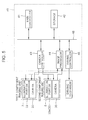
- the component mounting device further includes a controller 40 depicted in Fig. 5 .
- the controller 40 includes a CPU that executes logical operations, a ROM that stores various programs for controlling the CPU, a RAM that temporarily stores various data, an HDD and other components.
- the controller 40 includes a main controller 41, a storage 42, a camera controller 43, an image processor 44 and a driving controller 45, which are connected such that signals can be exchanged via a bus.
- the main controller 41 executes the component mounting operation by comprehensively controlling the head unit driving mechanism, the head driving mechanism and other driving mechanisms via the driving controller 45 according to the mounting programs stored in the storage 42.
- the main controller 41 controls the height positions of the front row heads 16A and the rear row heads 16B and the driving of the head unit 6 using the driving controller 45, and controls the exposure timing of the cameras 20 and 30 in the respective component imaging units 7 and 8 using the camera controller 43.
- the image processor 44 performs predetermined image processing on the image data from the cameras 20 and 30, and based on the processed image, the main controller 41 recognizes the component holding state of each mounting head 16.
- the head unit driving mechanism corresponds to the moving means of the present invention
- the main controller 41, the camera controller 43 and the driving controller 45 correspond to the imaging control means and the mounting control means of the present invention.
- the component mounting operation is performed as follows based on the control by the controller 40. First the head unit 6 moves onto the component supply portions 4 and 5, and the respective mounting heads 16 hold the components by suction. After the components are held by suction, the head unit 6 passes through the first component imaging unit 7 in the X direction (white arrow direction in Fig. 4 ) along the predetermined path, and during this passing the components held by the respective mounting heads 16 in the front row and the rear row are imaged by the respective imaging units 7 and 8.
- the head unit 6 moves in the X direction at a predetermined speed.
- the lighting timing of the illumination portion 22 on the first component imaging unit 7 is controlled so that the illumination portion 22 turns ON at a timing when each component C reaches above the camera 20, whereby each component C is imaged from below by the first component imaging unit 7. Further, as illustrated in Fig.
- the lighting timing of the illumination portion 32 is controlled (in other words, the exposure timing is controlled) so that the illumination portion 32 turns ON at a timing when a holding component C of the front row head 16A reaches a position corresponding to the first light-guiding portion 34 of the optical system 34 (first component imaging position), and a holding component C of the rear row head 16B reaches a position corresponding to the second light-guiding portion 34B (second component imaging position), whereby projection images of the holding components C held by the adjacent two heads 16A and 16B are captured from the side (+Y direction side) by the second component imaging unit 8.
- the optical length is set such that a focused image of the holding component C of the front row head 16A is obtained
- the optical length is set such that a focused image of the holding component C of the rear row head 16B is obtained, hence good focused images can be obtained for any of the heads 16A and 16B.
- the suction state of the components C held by the respective mounting heads 16 positional shift and inclination of a component with respect to the mounting head 16 in the X direction, Y direction and R direction
- the defects of the components C are recognized by the main controller 41, based on the bottom surface image (reflection image) of each component C imaged by the first component imaging unit 7 and a projection image imaged by the second component imaging unit 8 from the side of each component C.
- each component C is appropriately mounted on each placement position of the substrate 3 by the main controller 41, which controls the position of the head unit 6, the rotation angle of the mounting heads 16 or the like using the driving controller 45, so as to correct the suction position error of the component C according to the component recognition result.
- the head unit 6 moves to the position on the component disposal box (outside the drawings) and disposes the disposal target component C. Thereby one mounting operation cycle completes, and by repeating this operation as necessary, all required components are mounted on the substrate 3.
- the head unit 6 can equip many mounting heads 16 to perform the mounting operation of the components C efficiently, and the head unit 6 can be constructed to be compact in the X direction. Furthermore, the projection images of the holding components C of the respective mounting heads 16 arranged in the front row and the rear row can be obtained from the side equally with good quality, hence components can be efficiently recognized based on the projected images merely by moving the head unit 6 once in one direction with respect to the first component imaging unit 7; just like a conventional device having only one row of mounting heads.
- the second component imaging unit 8 captures a projection image of the components C, but may also capture a reflection image of the components C.
- Fig. 6 is an example of this embodiment.
- the first mirror 35a is a half mirror.
- the illumination portion 32 is constructed such that the illumination light is directly irradiated onto the holding components C of the respective heads 16A and 16B which are positioned at the same imaging height, from the light source 33a disposed at the same height as the first mirror 35a and on the front side (+Y direction side) of the first mirror 35a, using via the first mirror 35a.
- the illumination light reflected by the holding component C of the front row head 16A (that is, the light from this component to form the reflected image of the component) is reflected by the first mirror 35a to the fifth mirror 35e, and is guided to the camera 30. Further, the illumination light reflected by the holding component C of the rear row head 16B is reflected by the first mirror 35a, and is guided to the camera 30. Thereby the reflection images of the components C held by the respective heads 16A and 16B are imaged by the camera 30 respectively.
- Fig. 7 and Fig. 8 are schematic diagrams of a component imaging unit of a component mounting device according to Embodiment 2.
- the configuration of the second component imaging unit 8 is different from that of Embodiment 1 in terms of the following aspects, and the rest of the configuration is basically the same as the component mounting device of Embodiment 1.
- a component element the same as Embodiment 1 is denoted with the same reference symbol, for which description is omitted, and primarily a difference from Embodiment 1 will be described.
- the illumination portion 32 includes a first light source 333a that irradiates illumination light having a first wavelength, and a second light source 333b that irradiates illumination light having a second wavelength that is different from the first wavelength.
- the first light source 333a is disposed on the -X direction side of the center position of the illumination portion 32 in the X direction, and the second light source 333b is disposed on the +X direction side thereof.
- the illumination portion 32 also includes a diffusion plate 37 and a light source side optical filter 38.
- the diffusion plate 37 and the light source side optical filter 38 are disposed between the light sources 333a and 333b and an illumination mirror 33b.
- the light source side optical filter 38 includes a first light source side filter portion 38a and a second light source side filter portion 38b. As illustrated in Fig. 8 , the first light source side filter portion 38a is disposed on the -X direction side of the center position of the light source side optical filter 38 in the X direction, and removes the light components having the second wavelength from the illumination light.
- the second light source side filter portion 38b is disposed on the +X direction side of the center portion of the light source side optical filter 38 in the X direction, and removes the light components having the first wavelength from the illumination light. Because of this configuration, the illumination portion 32 irradiates the illumination light having the first wavelength to components C on the -X direction side of the center position in the X direction, and irradiates the illumination light having the second wavelength to components C on the +X direction side thereof.
- the optical system 34 includes a camera side optical filter 39.
- the camera side optical filter 39 is disposed between the holding components C of the mounting heads 16 and the first mirror 35a.
- the camera side optical filter 39 includes a first camera side filter portion 39a and a second camera side filter portion 39b.
- the first camera side filter portion 39a is disposed on the -X direction side of the center position of the camera side optical filter 39 in the X direction, and allows the light components having the first wavelength to transmit while removing the light components having the second wavelength.
- the second camera side filter portion 39b is disposed on the +X direction side of the center position of the camera side optical filter 39 in the X direction, and allows the light components having the second wavelength to transmit while removing the light components having the first wavelength.
- the illumination light having the first wavelength is irradiated onto the holding component C of the front row head 16A (corresponding to the first component of the present invention), which is disposed in a position corresponding to the first light-guiding portion 34A, as illustrated in Fig. 8 . Then the projection image thereof is guided to the camera 30 after the light components having the second wavelength are removed by the camera side optical filter 39 (first camera side filter portion 39a).
- the illumination light having the second wavelength is irradiated onto the holding component C of the rear row head 16B (corresponding to the second component of the present invention), which is disposed in a position corresponding to the second light-guiding portion 34B. Then the projection image thereof is guided to the camera 30 after the light components having the first wavelength are removed by the camera side optical filter 39 (second camera side filter portion 39b).
- the projection images of the components C held by the adjacent heads 16A and 16B can be captured more clearly.
- the illumination light including the light components having the same wavelengths
- the illumination light contacts the holding component C of each head 16A and 16B and then scatters, and the scattered light mixes with the projection image of the component C, whereby the contrast of each projection image drops.
- the second component imaging unit 8 of Embodiment 2 even if the scattered light having the second wavelength that scatted by contacting the holding component C of the rear row head 16B mixes with the projection image of the holding component C of the front row head 16A, the light components having the second wavelength are removed by the camera side optical filter 39 (first camera side filter portion 39a). For the projection image of the holding component C of the rear row head 16B as well, the light components having the first wavelength are removed by the camera side optical filter 39 (second camera side filter portion 39b). Therefore according to the second component imaging unit 8 of Embodiment 2, the influence of the scattered light can be removed from the projection image of any component C held by each head 16A and 16B. As a consequence, a clear projection image with good contrast can be obtained for any holding component C.
- the light source side optical filter 38 and the camera side optical filter 39 correspond to the filter means of the present invention
- the first light source side filter portion 38a and the first camera side filter portion 39a correspond to the first filter (the first upstream side filter and the first downstream side filter) of the present invention
- the second light source side filter portion 38b and the second camera side filter portion 39b correspond to the second filter (the second upstream side filter and the second downstream side filter) of the present invention.
- the second component imaging unit 8 includes both the light source side optical filter 38 and the camera side optical filter 39, but may have a configuration that includes only one of these filters.
- the second component imaging unit 8 may also have a configuration that includes only one of the first filter (the first light source side filter portion 38a and the first camera side filter portion 39a) and the second filter (the second light source side filter portion 38b and the second camera side filter portion 39b).
- the filter means is appropriately disposed such that the influence of the scattered light is suppressed by removing specific light components, and projection images with good contrast are obtained as the projection images of the components C held by the adjacent heads 16A and 16B.
- the illumination portion 32 including the light sources 333a and 333b that irradiate illumination light of the light components having mutually different wavelengths
- general white light sources may be used as the light sources, and filter means may be placed on each optical path from the light source to the CCD area sensor, so that light including different light components enter the CCE area sensor as projection images of the components C held by the adjacent heads 16A and 16B.
- the illumination light having the first wavelengths allows the illumination light having the first wavelengths to pass and removes the illumination light having the other wavelengths, so that the illumination light having the first wavelength, out of the illumination light from the white light source, is irradiated onto the holding component C of the front row head 16A.
- the second light source side filter portion 38b disposed on the +X side allows the illumination light having the second wavelength to pass and removes the illumination light having the other wavelength, so that the illumination light having the second wavelength, out of the illumination light from the white light source, is irradiated onto the holding component C of the rear row head 16B.
- the first camera side filter portion 39a disposed on the -X side in Fig.
- the second camera side filter portion 39b disposed on the -X side allows the projection image of the light components having the second wavelength to pass and removes the projection images of the light components having the other wavelengths, so that the projection image of the light components having the second wavelength, out of the projection images of the holding component C of the rear row head 16B, is guided to the camera 30.
- Fig. 9 and Fig. 10 are schematic diagrams of a component imaging unit of a component mounting device according to Embodiment 3.
- the configuration of the second component imaging unit 8 is different from that of Embodiment 1 in terms of the following aspects, and the rest of the configuration is basically the same as the component mounting device of Embodiment 1.
- a composing element the same as Embodiment 1 is denoted with the same reference symbol, for which description is omitted, and primarily a difference from Embodiment 1 will be described.
- the second component imaging unit 8 has a camera 30 that includes a CCD linear sensor (line sensor 31). This camera 30 is disposed such that the picture elements line in the Y direction, sequentially captures the projection images of one line of components C held by the respective mounting heads 16 as the head unit 6 moves in the X direction, and outputs this image data to the controller 40.
- a CCD linear sensor line sensor 31
- the first mirror 35a is a dedicated mirror for guiding a projection image of a holding component C of the front row head 16A out of the mounting heads 16 (this mirror 35a is called the "first mirror for the front row 35a" in this embodiment), and separate from the first mirror for the front row 35a, a first mirror 35a' constituted by a half mirror for guiding a projection image of a holding component C of the rear row head 16B (this mirror 35a' is called the "first mirror for the rear row 35a"' in this embodiment) is disposed.
- the first mirror for the rear row 35a' is disposed between the first mirror for the front row 35a and the holding components C of the mounting heads 16.
- the first light-guiding portion 34A guides an image that transmits through the first mirror for the rear row 35a', out of the projection images of the component C held by the front row head 16A to an area on the front side (+Y direction side) of the line sensor 31 while reflecting the image a plurality of times using the first mirror for the front row 35a and the second mirror 35b to the fifth mirror 35e.
- the second light-guiding portion 34B reflects a projection image of a component C held by the rear row head 16B using the first mirror for the rear row 35a', and guides the image to an area on the rear side (-Y direction side) of the line sensor 31.
- the light-guiding portions 34A and 34B are lined up in the Y direction, and guide the projection images of the components C held by the respective heads 16A and 16B to the camera 30 maintaining the same position in the X direction as the head unit 6 moves.
- the first component imaging position and the second component imaging position are set in the same position in the X direction.
- the holding components C of the respective heads 16A and 16B move between the optical system 34 and the illumination portion 32 along the predetermined path in the X direction as the head unit 6 moves, in a state where the illumination light is being irradiated from the illumination portion 32, and by this movement, and the projection images of the components C held by the respective heads 16A and 16B are alternately captured by the camera 30.
- the projection images of the holding components C of the respective heads 16A and 16B are all reflected by the first mirror for the front row 35a and form images on the line sensor 31 via the first light-guiding portion 34A, or are reflected by the first mirror for the rear row 35a' and form images on the line sensor 31 via the second light-guiding portion 34B.
- the projection image formed on the line sensor 31 via the first light-guiding portion 34A is located in the front side area of the line sensor 31
- the projection image formed on the line sensor 31 via the second light-guiding portion 34B is located in the rear side area of the line sensor 31.
- the optical path length of the first light-guiding portion 34A is set so that a focused image of the holding component C of the front row head 16A can be obtained
- the optical path length of the second light-guiding portion 34B is set so that a focused image of the holding component C of the rear row head 16B can be obtained. Therefore even if the projection image of the holding component C of the front row head 16A is guided to the camera 30 by the second light-guiding portion 34B, this projection image of the holding component C of the front row head 16A becomes out of focus and unclear. For the same reasons, even if the projection image of the holding component C of the rear row head 16B is guided to the camera 30 by the first light-guiding portion 34A, this projection image becomes out of focus and unclear.
- the image processor 44 performs processing to extract only images in the front side area of the line sensor 31, for the projection image of the holding component C of the front row head 16A, and performs processing to extract only images in the rear side area of the line sensor 31, for the projection image of the component C held by the rear row head 16B.
- well focused images are obtained respectively as projection images of the components C held by the respective heads 16A and 16B.
- the second component imaging unit 8 is not limited to the configuration of capturing a projection image of a component C, but may capture a reflection image of a component C.
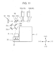
- Fig. 11 is an example of this embodiment.
- a half mirror is used as the first mirror for the front row 35a.
- the illumination portion 32 irradiates illumination light from the light source 33a disposed on the front side (+Y direction side) of the first mirror for the front row 35a onto the holding components C of the respective heads 16A and 16B via the first mirror for the front row 35a and the first mirror for the rear row 35a'.
- the illumination light reflected by the holding component C of the front row head 16A that is, the reflection image
- transmits through the first mirror for the rear row 35a' and is reflected by the first mirror for the front row 35a and the second mirror 35b to the fifth mirror 35e, and is guided to the front side area of the line sensor 31 of the camera 30.
- the reflection image of the holding component C of the rear row head 16B is reflected by the first mirror for the rear row 35a' and is guided to the rear side area of the line sensor 31 of the camera 30. Thereby the reflection images of the components C held by the respective heads 16A and 16B are captured by the camera 30.
- Fig. 12 and Fig. 13 are schematic diagrams of a component mounting device according to Embodiment 4.
- Fig. 12 is a schematic front view of the component mounting device
- Fig. 13 is a schematic side view of the head unit 6.
- the second component imaging unit 8 is equipped in the head unit 6, and the rest of the configuration is basically the same as the component mounting device of Embodiment 1.
- a composing element the same as Embodiment 1 is denoted with the same reference symbol, for which description is omitted, and primarily a difference from Embodiment 1 will be described.
- the second component imaging unit 8 includes the camera 30, the optical system 34 and a case 8a where these composing elements are housed, and the illumination portion 32 is disposed separately from the second component imaging unit 8.
- the second component imaging unit 8 is disposed on the rear side (-Y direction side) of the heads 16A and 16B, and is movably supported to the bottom face of the head unit 6 via a pair of fixed rails 52 that extends in the X direction.
- a ball screw shaft 53 which is rotary-driven by the driving of a servo motor located outside the drawings, is screwed into the case 8a, and the servo motor is controlled by the main controller 41 via the driving controller 45, whereby the second component imaging unit 8 moves in the X direction.
- the servo motor and the ball screw shaft 53 correspond to the moving means of the present invention.
- the illumination portion 32 does not include the illumination mirror 33b, and a plurality of light sources 33a are secured to a mounting member that suspend from the front edge of the head unit 6, so that the illumination light is directly irradiated backward onto the components C held by the respective heads 16A and 16B.
- Each light source 33a is disposed in the front side of each head 16A and 16B.
- the camera 30 of the second component imaging unit 8 is equipped in the case 8a so as to face the front side of the device. By this configuration, the second component imaging unit 8 moves in the X direction with respect to the head unit 6 and each light source 33a is sequentially turned ON from one end in the X direction, whereby the projection images of the components C held by the respective heads 16A and 16B are captured by the camera 30.
- the second light-guiding portion 34B is constructed such that the projection image of the component C held by the rear row head 16B is reflected by a plurality of mirrors and is then guided to the camera 30.
- the optical path lengths of the respective light-guiding portions 34A and 34B are set such that focused images can be obtained as the projection images of the respective components C.
- the second component imaging unit 8 moves with respect to the head unit 6, as indicated by the arrows in Fig. 12 , in a state where each mounting head 16 is disposed in a predetermined component imaging height position.
- each light source 33a sequentially turns ON, whereby the projection images of the components C held by the respective heads 16A and 16B are captured by the camera 30.
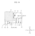
- the second component imaging unit 8 is movably supported to the head unit 6, but as illustrated in Fig. 14 , the second component imaging unit 8 may be fixed to an appropriate position of the unit support member 12, such as a center position in the X direction.
- the head unit 6 moves in the X direction in a state where the respective mounting heads 16 are disposed in a predetermined component imaging height position, whereby the projection images of the components C held by the respective heads 16A and 16B are captured by the camera 30 during the movement.
- a dedicated driving mechanism for moving the second component imaging unit 8 is unnecessary, and the configuration can be simplified and cost can be decreased compared with the example illustrated in Fig. 12 and Fig. 13 .
- the X axis servo motor 15 and the ball screw shaft 14 correspond to the moving means of the present invention.
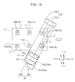
- Fig. 15 illustrates a component mounting device according to Embodiment 5.
- Fig. 15 is a schematic plan view of the head unit 6 and the second component imaging unit 8 of the component mounting device.
- the configuration of the head unit 6 and the second component imaging unit 8 is different from that of Embodiment 1 in terms of the following aspects, and the rest of the configuration is basically the same as the component mounting device of Embodiment 1.
- a composing element the same as Embodiment 1 is denoted with the same reference symbol, for which description is omitted, and primarily a difference from Embodiment 1 will be described in detail.
- the front row heads 16A and the rear row heads 16B of the head unit 6 are aligned as illustrated in Fig. 15 , that is, arranged such that the respective front row heads 16A and the respective rear row heads 16B are disposed in the same position in the X direction.
- the distances between the respective mounting heads 16 are set so that the mounting heads 16 shift from each other in a direction perpendicular to the direction that is a predetermined angle ⁇ inclined from the Y direction (corresponding to the specific direction of the present invention; the broken line arrow direction indicated in Fig. 15 ) when the mounting heads 16 are viewed from the side face in the inclined direction. Further, as illustrated in Fig.
- the second component imaging unit 8 is constructed so as to capture the projection images of the holding components C of the respective heads 16A and 16B, while irradiating the illumination light in a direction parallel with the inclined direction.
- the second component imaging unit 8 of the Embodiment 5 is set in a position where the first component imaging position and the second component imaging position are the same position in the X direction.
- the first component imaging unit 7 is omitted for simplification.
- the mounting heads 16 are aligned while the second component imaging unit 8 is inclined in the Y direction, so that the projection images of the components C held by the heads 16A and 16B can be captured.
- the head unit 6 can obtain focused side face images of the holding components C of all the mounting heads 16, just like Embodiment 1, even if the front row head 16A and the rear row head 16B are aligned.
- Fig. 16 is a schematic diagram of a component imaging unit of a component mounting device according to Embodiment 6.
- the configuration of the second component imaging unit 8 is different from that of Embodiment 3 ( Fig. 9 and Fig. 10 ) in terms of the following aspects, and the rest of the configuration is basically the same as the component mounting device of Embodiment 3.
- a composing element the same as Embodiment 3 is denoted with the same reference symbol, for which description is omitted, and primarily a difference from Embodiment 1 will be described in detail.
- the front row heads 16A and the rear row heads 16B are equipped in the head unit 6 in an aligned state, that is, in a state where the respective front row heads 16A and the respective rear row heads 16B are arranged in the same position in the X direction, just like the configuration illustrated in Fig. 15 .
- the first mirror for the rear row 35a' of the second light-guiding portion 34B is located in a position lower than the first mirror for the front row 35a of the first light-guiding portion 34A.
- the first component imaging position is set to a position that is higher than the second component imaging position.
- the front row heads 16A and the rear row heads 16B are controlled to have mutually different height positions so that a projection image of a holding component C of the front row head 16A is reflected by the first mirror for the front row 35a, while a projection image of a holding component C of the rear row head 16B is reflected by the first mirror for the rear row 35a', as illustrated in Fig. 16 .
- the main controller 41 controls the imaging height positions of the front row heads 16A and the rear row heads 16B, so that the height position of a holding component C of the front row head 16A becomes the same as the height position of the first mirror for the front row 35a, and the height position of a holding component C of the rear row head 16B becomes the same as the height of the first mirror for the rear row 35a'.
- Embodiment 6 a focused side face image can be obtained for the holding components C of all the mounting heads 16 respectively, even if the front row heads 16A and the rear row heads 16B are aligned.
- component mounting devices of the embodiments described above are examples of the preferred embodiments of the component mounting device according to the present invention (component mounting device to which the component imaging device according to the present invention is applied), and a concrete configuration thereof can be modified without departing from the true spirit and scope of the invention.
- Embodiment 1 For example, a configuration combining each configuration of Embodiment 1 to Embodiment 6 may be used.
- the filter means of Embodiment 2 may be used for Embodiment 3 to Embodiment 6. According to this configuration, images with better contrast can be obtained as images of components C held by the heads 16A and 16B which are adjacent to each other.
- images of the holding components C of the mounting head 16 are reflected primarily by the mirrors, and are guided to the camera 30, but prisms may be used or mirrors and prisms may be combined.
- the first and second component imaging units 7 and 8 are disposed only between the trays 5a and 5b on the base 1, but similar component imaging units 7 and 8 may be disposed for the component supply portion 4 as well.
- the component supply portion 4 is divided into two component supply portions, which are separated by a gap in the X direction, and the extra component imaging units having the same configuration as the component imaging units 7 and 8 are disposed in the position between these two component supply portions on the base 1.
- the extra component imaging units are disposed symmetrically with respect to the component imaging units 7 and 8, that is, in a state where the component imaging units 7 and 8 are rotated 180° in the R directions.
- the head unit 6 can be moved to the extra component imaging units disposed on the component supply portion 4 side so as to recognize the component holding state by each head 16A and 16B. Thereby the moving distance of the head unit 6 can be decreased, and the mounting cycle time can be decreased.
- the head unit 6 is constituted by the plurality of mounting heads 16 which are arranged in the front row and the rear row, but the present invention can be applied to the case of three or more rows of mounting heads 16.
- the rows adjacent to each other form the relationship of the front row and the rear row described above, hence a functional effect equivalent to the component mounting device (component imaging unit) of Embodiments 1 to 6 can be demonstrated by applying the configuration of these embodiments.
- focused side face images are obtained for the holding components C of all the mounting heads 16, but obtaining an image of a holding component C may be omitted if it is not necessary to obtain the side face image thereof.
- the height of the mounting head 16 holding a component of which image is not obtained is controlled to be higher than the imaging height position, so that this holding component C is located higher to be removed from the optical path of the optical system 34, from the illumination portion 32 to the first mirrors 35a and 35a'.
- a component imaging device has: a head unit that has a first head row that includes a plurality of vertically movable heads arranged in a row in a first direction, and a second head row that includes a plurality of vertically movable heads arranged in a row in the first direction and that is arranged in a second direction perpendicular to the first direction with respect to the first head row; an imaging unit that images components held by the respective heads from a position on one side of the second direction; illumination means for irradiating illumination light for imaging on the components held by the heads; moving means for relatively moving the head unit with respect to the imaging unit along a predetermined path which is parallel with the first direction, in order to image the components held by the heads; and imaging control means for performing control related to the component imaging operation, wherein the imaging unit includes an image sensor and an optical system that guides light from a component held by the head for generating an image of the component, to the image sensor, the optical system includes: a first light-guiding portion that guides, to
- a focused image of a component held by each head of the first head row is obtained since the light from the component is guided to the image sensor by the first light-guiding portion of the optical system.
- a focused image of a component held by each head of the second head row is also obtained since the light from the component is guided to the image sensor by the second light-guiding portion of the optical system. Therefore equally good focused images can be obtained for any holding components of both head rows.
- "light from a component” refers to both light to form a projection image of the component and light to form a reflection image of the component.
- the heads of the first head row and the heads of the second head row are arranged to be shifted from each other in a direction perpendicular to a specific direction crossing the first direction when viewed from the specific direction, the first component imaging position and the second component imaging position are set at the same height, and the imaging unit images components held by the heads of the respective head rows from one side of the specific direction.
- the specific direction may be a direction perpendicular to the first direction, that is the second direction, or may be a direction inclined from the first direction.
- the head unit and the imaging unit are relatively moved in the first direction in a state where all the heads are disposed in the same height position. Thereby the focused images of the components held by all the heads from the side direction can be obtained.
- Another concrete configuration is that the respective heads of the first head row and the respective heads of the second head row are disposed in the same position when viewed from the second direction, the first component imaging position is set to a position higher than the second component imaging position, and the imaging unit images components held by the heads of the respective head rows from one side of the specific direction.
- the head unit and the imaging unit are relatively moved in the first direction in a state where the respective heads of the first head row and the respective heads of the second head row are disposed in mutually different height positions. Thereby the images of the components held by the heads of the respective head rows from the side direction can be obtained. According to this configuration, focused images of the components held by all the heads from the side direction can be obtained even if the structure is the same as a conventional head unit, where the heads of the respective head rows are aligned.
- the first light-guiding portion and the second light-guiding portion allow mutually different areas of the image sensor to simultaneously receive light from two components held by a pair of heads which belong to mutually different head rows and are adjacent to each other.
- the illumination means irradiates illumination light onto a pair of a first component and a second component which are adjacent to each other, and the component imaging device further comprises filter means for removing light having specific wavelength components in an optical path from the illumination means to the image sensor, so that the light from the first component that enters the image sensor and the light from the second component that enters the image sensor include mutually different wavelength components.
- this component imaging device a phenomenon where the light from the first component and the light from the second component adjacent to the first component influence each other, and where the contrast of each component image drops, can be suppressed.
- the illumination means includes a first light source that irradiates illumination light having a first wavelength onto the first component, and a second light source that irradiates illumination light having a second wavelength, which is different from the first wavelength, onto the second component
- the filter means includes at least one of a first filter and a second filter, where the first filter removes light having the second wavelength components so that the light from the first component that enters the image sensor does not include the light components having the second wavelength, and the second filter removes light having the first wavelength components so that the light from the second component that enters the image sensor does not include the light components of the first wavelength.
- the light from the first component and the light from the second component adjacent to the first component include only mutually different wavelength components, hence the contrast of the respective component images become good, and high quality component images of the first component and the second component can be obtained.
- the first filter includes at least one of a first upstream side filter that removes light components having a second wavelength out of the illumination light having a first wavelength irradiated from the first light source onto the first component, and a first downstream side filter that removes light components having the second wavelength out of the light from the first component
- the second filter includes at least one of a second upstream side filter that removes light components having a first wavelength out of the illumination light having a second wavelength irradiated from the second light source onto the second component, and a second downstream side filter that removes the light components having the first wavelength out of the light from the second component.
- the contrast of each component image further improves and even higher quality component images can be obtained as the component images of the first component and the second component.
- a component mounting device is a component mounting device that extracts components from a component supply portion and mounts the components on a substrate, comprising: any of the component imaging devices described above; and mounting control means for mounting components held by the respective heads of the head unit on a substrate by controlling the moving means of the component imaging device.
- components can be mounted efficiently by equipping many heads to a head unit while limiting the size of the head unit from becoming large, and the components held by the heads of the respective head rows can be imaged and recognized from the side with equally good quality.
- the present invention is a technique that is applied to a component mounting device, and when a plurality of heads are divided into a plurality of rows and are equipped to the head unit in this state, this technique allows imaging the components held by the respective heads from the side direction with equally good quality. Therefore the present invention is particularly useful in the field of the manufacture of component mounting substrates.
Landscapes
- Engineering & Computer Science (AREA)
- Multimedia (AREA)
- Signal Processing (AREA)
- Manufacturing & Machinery (AREA)
- Microelectronics & Electronic Packaging (AREA)
- Operations Research (AREA)
- Human Computer Interaction (AREA)
- Supply And Installment Of Electrical Components (AREA)
- Studio Devices (AREA)
Abstract
Description
- The present invention relates to a component imaging device that images a component, held by a head, from the side thereof, and a component mounting device equipped with the component imaging device.
- A component mounting device which extracts a component from a component supply portion and mounts the component on a mounting position on the substrate using a component mounting head has been known. As this type of component mounting device, a device that recognizes a state of the head holding a component in advance prior to mounting the component on the substrate, by imaging the component held by the head from the side thereof, is known. For example,
Patent Document 1 discloses a component mounting device including a head unit where a plurality of mounting heads are disposed in a line, wherein an illumination device that irradiates illumination light onto a component held by each head from the side is equipped in the head unit, and a camera is fixed to a support member that supports the head unit. In this component mounting device, a projection image of a component held by each head is imaged by the camera while the head unit is moving with respect to the support member, and the state of each head holding the component is recognized based on this image. - Lately a number of heads disposed in the head unit tends to increase in order to make the mounting operation more efficient. In this case, a plurality of heads separated into a plurality of rows may be disposed in the head unit, such as an arrangement of a front row and a rear row, in order to prevent the head unit from becoming large.
- However if the plurality of heads are arranged in a front row and a rear row, the components held by the heads, which are lined up in the front and rear rows, overlap with each other, which makes it difficult to capture the projection image of each component.
- In this case, components of the respective heads arranged in the front and rear rows could be imaged from the side by mutually shifting the locations of the heads in each row, but if the component held by the respective heads are imaged by the same camera (image sensor) simply shift the heads of each row, the distance between each head of the camera becomes different depending on the row, which makes it difficult to image all the components held by the heads with equal image quality.
- Patent Document 1: Japanese Patent Application Laid-Open No.
2005-347412 - It is an object of the present invention that when a plurality of component mounting heads, arranged into a plurality of rows, are disposed in a head unit, components held by the respective heads are imaged from the side thereof with equally good quality.
- A component imaging device according to an aspect of the present invention has: a head unit that has a first head row that includes a plurality of vertically movable heads arranged in a row in a first direction, and a second head row that includes a plurality of vertically movable heads arranged in a row in the first direction and that is arranged in a second direction perpendicular to the first direction with respect to the first head row; an imaging unit that images components held by the respective heads from a position on one side of the second direction; illumination means for irradiating illumination light for imaging on the components held by the heads; moving means for relatively moving the head unit with respect to the imaging unit along a predetermined path which is parallel with the first direction, in order to image the components held by the heads; and imaging control means for performing control related to the component imaging operation, wherein the imaging unit includes an image sensor and an optical system that guides light from a component held by the head for generating an image of the component, to the image sensor, the optical system includes: a first light-guiding portion that guides, to the image sensor, light from a component that has reached a predetermined first component imaging position, out of the components held by the respective heads of the first head row, as the head unit relatively moves along the predetermined path with respect to the imaging unit; and a second light-guiding portion that guides, to the image sensor, light from a component that has reached a predetermined second component imaging position, out of the components held by the respective heads of the second head row, an optical path length from the first component imaging position to the image sensor is set for the first light-guiding portion so as to obtain a focused image of a component held by a head of the first head row, an optical path length from the second component imaging position to the image sensor is set for the second light-guiding portion so as to obtain a focused image of a component held by a head of the second head row, and the imaging control means controls height positions of the heads and an exposure timing of the image sensor based on the respective component imaging positions, so that when the head unit relatively moves along the predetermined path with respect to the imaging unit, light from a component held by a head of the first head row is guided to the image sensor by the first light-guiding portion, and light from a component held by a head of the second head row is guided to the image sensor by the second light-guiding portion.
- A component mounting device according to an aspect of the present invention is a component mounting device that extracts components from a component supply portion and mounts the components on a substrate, comprising: the component imaging device described above; and mounting control means for mounting components held by the respective heads of the head unit on a substrate by controlling the moving means described above.
-
-
Fig. 1 is a schematic plan view of a component mounting device (component mounting device equipped with the component imaging device according to the present invention) according toEmbodiment 1 of the present invention. -
Fig. 2 is a schematic front view of the component mounting device inFig. 1 . -
Fig. 3 is a schematic side view of a component imaging unit. -
Fig. 4 is a schematic plan view of the component imaging unit. -
Fig. 5 is a block diagram depicting a control system of the component mounting device. -
Fig. 6 is a schematic side view of a modification of the component imaging unit. -
Fig. 7 is a schematic side view of a component imaging unit equipped in a component mounting device according toEmbodiment 2. -
Fig. 8 is a schematic plan view of the component imaging unit. -
Fig. 9 is a schematic side view of a component imaging unit equipped in a component mounting device according toEmbodiment 3. -
Fig. 10 is a schematic plan view of the component imaging unit. -
Fig. 11 is a schematic side view of a modification of the component imaging unit. -
Fig. 12 is a schematic front view of a component mounting device according toEmbodiment 4. -
Fig. 13 is a schematic side view of a head unit and a component imaging unit. -
Fig. 14 is a schematic side view of a head unit, head unit support member, and a component imaging unit according to a modification ofEmbodiment 4. -
Fig. 15 is a schematic plan view of a component imaging unit equipped in a component mounting device according toEmbodiment 5. -
Fig. 16 is a schematic side view of a component imaging unit equipped in a component mounting device according toEmbodiment 6. - Embodiments of the present invention will now be described with reference to the accompanying drawings.
-
Fig. 1 andFig. 2 are schematic diagrams of a component mounting device according to the present invention (component mounting device equipped with a component imaging device according to the present invention).Fig. 1 is a plan view andFig. 2 is a front view depicting the component mounting device schematically. InFig. 1 ,Fig. 2 and in the drawings to be described later, the rectangular coordinate axes X, Y and Z are shown in order to clarify the directional relationship. - The component mounting device includes a
base 1, asubstrate transporting mechanism 2 that is disposed on thebase 1 and transports asubstrate 3, such as a printed wiring board (PWB) in the X direction,component supply portions mounting head unit 6, a head unit driving mechanism for driving thehead unit 6, a component imaging unit for recognizing the components held by thehead unit 6 and the like. - The
substrate transporting mechanism 2 includes a pair ofconveyors 2a for transporting thesubstrate 3 on thebase 1. Theconveyors 2a receive thesubstrate 3 from the right side (-X direction) in the drawings, and transport thesubstrate 3 to a predetermined mounting operation position (position illustrated in the drawings), and hold thesubstrate 3 there using a holding device (not illustrated). After the mounting operation, theconveyors 2a release holding of thesubstrate 3 and transport thesubstrate 3 out to the left side (+X direction side) in the drawings. - The
component supply portions component supply portion 4, which is on the rear side of the device (-Y direction side) out of thecomponent supply portions tape feeders 4a line up in the X direction along thesubstrate transporting mechanism 2. Each of thetape feeders 4a includes a reel where a tape storing and holding chip components, such as ICs, transistors and capacitors, are wound, and supplies a component to a predetermined component supply position near thesubstrate transporting mechanism 2 while feeding the tape from the reel intermittently. On thecomponent supply portion 5, which is on the front side of the device (+Y direction side), on the other hand,trays tray - The
head unit 6 is for extracting components from thecomponent supply portions substrate 3, and is disposed above thesubstrate transporting mechanism 2 and thecomponent supply portions - The
head unit 6 can be moved in the X direction and the Y direction within a predetermined area by the head unit driving mechanism. The head unit driving mechanism is secured to a pair of elevatedframes 1a disposed on thebase 1 respectively, and includes a pair offixed rails 9 which extend parallel in the Y direction, aunit support member 12 which is supported by thefixed rails 9 and extends in the X direction, and aball screw shaft 10 which is screwed into theunit support member 12, and is driven by the Yaxis servo motor 11. The head unit driving mechanism also includes a fixedrail 13 which is secured in theunit support member 12 and supports thehead unit 6 so as to be movable in the X direction, and aball screw shaft 14 which is screwed into thehead unit 6 and is driven by the Xaxis servo motor 15 as a driving source. In other words, the head unit driving mechanism moves thehead unit 6 in the X direction via theball screw shaft 14 by the driving of the Xaxis servo motor 15, and moves theunit support member 12 in the Y direction via theball screw shaft 10 by the driving of the Yaxis servo motor 11. As a result, the head unit driving mechanism moves thehead unit 6 in the X direction and the Y direction within a predetermined area. - The
head unit 6 includes a plurality ofmounting heads 16 each of which has a nozzle to hold a component by suction at the tip, and a head driving mechanism that uses a servo motor (not illustrated) as a driving source, for ascending/descending themounting heads 16 with respect to the head unit 6 (movement in the Z direction), and for rotating themounting heads 16 around the center axis of the nozzle (rotation in the R direction inFig. 2 ). - There are a total of six
mounting heads 16, which are separated into three heads in a front row and three heads a rear row, and are arranged in the X direction in a line at a predetermined pitch P in each row. In the following description, a row of themounting heads 16 disposed on the front side of the device is called the "front row" (corresponding to the first head row of the present invention), and a row of themounting heads 16 disposed on the rear side of the device is called the "rear row" (corresponding to the second head row of the present invention), and when necessary, themounting heads 16 of the front row are called the "front row heads 16A", and themounting heads 16 of the rear row are called the "rear row heads 16B". In this embodiment, the X direction corresponds to the first direction of the present invention, and the Y direction corresponds to the second direction of the present invention. - The array pitch P of the
front row heads 16A and the array pitch P of therear row heads 16B are the same, and eachfront row head 16A is a half pitch (1/2 P) offset in the X (-X) direction with respect to eachrear row head 16B. Thereby twelvemounting heads 16 are arranged in a zigzag manner. To be more specific, when thefront row heads 16A and therear row heads 16B are disposed at the same height positions and viewed in the +Y direction (corresponding to the specific direction of the present invention), the sixmounting heads 16 are arranged in a zigzag manner so that the components held by therespective mounting heads 16 do not overlap with one another. - A nozzle of each
mounting head 16 can be connected to one of a negative pressure generator, a positive pressure generator, and the atmosphere via an electric switching valve. In other words, the nozzle can hold a component by suction by supplying negative pressure to the tip thereof, and release the hold of the component by supplying positive pressure. - The component imaging unit is for imaging the component so as to recognize the holding state of the component extracted from the
component supply portions mounting head 16. The component imaging unit is disposed in a position between thetrays base 1. In this embodiment, the first and secondcomponent imaging units Fig. 1 andFig. 3 , and the secondcomponent imaging unit 8 corresponds to the component imaging unit of the present invention. - The first
component imaging unit 7 is for imaging the components held by the mounting heads 16 mainly from the bottom, and as illustrated inFig. 3 , a component C held by each mounting head 16 (hereafter may be called the "holding component C") is imaged while the head unit 6 (mounting head 16) is relatively moving above the firstcomponent imaging unit 7 along a predetermined path parallel with the X direction. The firstcomponent imaging unit 7 includes acamera 20 that has a CCD area sensor, a lens or the like, and anillumination portion 22 that has such a light source as an LED to provide illumination light for imaging to the component C, and irradiates the illumination light onto the component C mainly from the bottom, images the reflection image thereof by thecamera 20, and outputs the image data to thecontroller 40, which is described later. - The second
component imaging unit 8 images a component C held by each mountinghead 16 from the side thereof. The secondcomponent imaging unit 8 images the holding component C of each mountinghead 16 while the head unit 6 (mounting head 16) moves above the firstcomponent imaging unit 7 along the predetermined path. - As illustrated in
Fig. 3 and Fig. 4 , the secondcomponent imaging unit 8 includes acamera 30 that has a CCD area sensor (image sensor), a lens and the like, anillumination portion 32 that provides backlight illumination light to the component C from the side, and anoptical system 34 that guides the transmitted light from the periphery of the component (that is, light from the component to generate a projection image of the component) to thecamera 30. In this embodiment, the secondcomponent imaging unit 8 includes the illumination portion 32 (corresponding to the illumination means of the present invention), but theillumination portion 32 may be separated from the secondcomponent imaging unit 8. - Out of the second
component imaging unit 8, thecamera 30 and theoptical system 34 are disposed on the front side (+Y direction side) of the firstcomponent imaging unit 7, and theillumination portion 32 is disposed on the rear side (-Y direction side) of the firstcomponent imaging unit 7. Theillumination portion 32 includes alight source 33a, such as an LED, for irradiating illumination light upward, and anillumination mirror 33b that refracts the illumination light at approximately right angles, so as to guide the light to the front side of the device. Because of this configuration, the secondcomponent imaging unit 8 irradiates the illumination light onto the component C using theillumination portion 32 in the direction from the rear side to the front side of the device, and guides the projection image thereof to thecamera 30 using theoptical system 34 so as to capture the image, and outputs the image data from thecamera 30 to thecontroller 40, which is described later. - The
illumination portion 32 has an illumination width which allows irradiating the illumination light onto each holding component C of a pair ofheads optical system 34 simultaneously guides the projection images of the respective holding components C of theheads camera 30. Thereby the secondcomponent imaging unit 8 can simultaneously image the respective holding components C of the pair ofheads - Concerning the
optical system 34, theoptical system 34 includes a first light-guidingportion 34A and a second light-guidingportion 34B for guiding the projection images of the components C held by theheads camera 30 respectively. The light-guidingportions portion 34A is located on the -X direction side, and the second light-guidingportion 34B is located on the +X direction side. In other words, when a component held by thefront row head 16A reaches a predetermined imaging position (called the "first component imaging position" when necessary) as thehead unit 6 moves along the predetermined path relative to the secondcomponent imaging unit 8, the first light-guidingportion 34A guides the projection image of this component to thecamera 30. On the other hand, when a component held by therear row head 16B reaches an imaging position which has the same height as the imaging position mentioned above and is adjacent to the imaging position in the +X direction (called the "second component imaging position" when necessary), the second light-guidingportion 34B guides this component to thecamera 30. - The first light-guiding
portion 34A and the second light-guidingportion 34B share afirst mirror 35a, which reflects the projection images of the respective holding components C of theheads first mirror 35a has an elongated shape in the X direction, and reflects the projection images of the respective holding components C of theheads portion 34A further includes asecond mirror 35b to afifth mirror 35e, which reflect the reflection image by thefirst mirror 35a a plurality of times (four times in this case) and guide the image downward, in a position corresponding to the half side (half in the -X direction side) in the longitudinal direction of thefirst mirror 35a. In other words, the first light-guidingportion 34A guides the projection image of the component C to thecamera 30 by reflecting the image a plurality of times using thefirst mirror 35a to thefifth mirror 35e, whereas the second light-guidingportion 34B guides the projection image of the component C to thecamera 30 by reflecting the image using only thefirst mirror 35a. As illustrated inFig. 4 , in the first light-guidingportion 34A, the optical path length from the first component imaging position (position of the holding component C of thefront row head 16A) to thecamera 30 is set such that the image of the component C is correctly focused, that is, a focused image of the component C is obtained when the holding component C of thefront row head 16A is placed in the first component imaging position. In the second light-guidingportion 34B, on the other hand, an optical path length from the second component imaging position (position of the holding component C of therear row head 16B) to thecamera 30 is set such that a focused image of the component C is obtained when the holding component C of therear row head 16B is placed in the second component imaging position. In other words, these light-guidingportions portion 34A, from (the holding component C of) thefront row head 16A to thecamera 30, and the optical length of the second light-guidingportion 34B, from (the holding component C of) therear row head 16B to thecamera 30, are the same. By this configuration, the secondcomponent imaging unit 8 can obtain equal quality focused images for the projection images of all the holding components C of the front row heads 16A and the rear row heads 16B. - In
Fig. 3 , the solid line indicates an optical path of the projection image of the component C held by thefront row head 16A (optical path by the first light-guidingportion 34A), and the broken line indicates an optical path of the projection image of the component C held by therear row head 16B (optical path by the second light-guidingportion 34B). InFig. 3 , a part of the optical path by the second light-guidingportion 34B (the optical path from thefirst mirror 35a to the camera 30) actually overlaps with the optical path of the first light-guidingportion 34A (optical path from thefirst mirror 35a to thesecond mirror 35b, and the optical path from thefifth mirror 35e to the camera 30), but the optical path by the second light-guidingportion 34B is intentionally shifted inFig. 3 in order to clearly show the optical path, therefore inFig. 3 , the optical length of the light-guidingportion 34A and that of the light-guidingportion 34B are not drawn to have the same distance. This shift of the optical paths of the light-guidingportions portions - In order to control the operation comprehensively, the component mounting device further includes a
controller 40 depicted inFig. 5 . Thecontroller 40 includes a CPU that executes logical operations, a ROM that stores various programs for controlling the CPU, a RAM that temporarily stores various data, an HDD and other components. As a functional configuration, thecontroller 40 includes amain controller 41, astorage 42, acamera controller 43, animage processor 44 and a drivingcontroller 45, which are connected such that signals can be exchanged via a bus. - The
main controller 41 executes the component mounting operation by comprehensively controlling the head unit driving mechanism, the head driving mechanism and other driving mechanisms via the drivingcontroller 45 according to the mounting programs stored in thestorage 42. In particular, after the mountinghead 16 descends in the Z direction and extracts the components from thecomponent supply portions main controller 41 controls the height positions of the front row heads 16A and the rear row heads 16B and the driving of thehead unit 6 using the drivingcontroller 45, and controls the exposure timing of thecameras component imaging units camera controller 43. - The
image processor 44 performs predetermined image processing on the image data from thecameras main controller 41 recognizes the component holding state of each mountinghead 16. In this embodiment, the head unit driving mechanism corresponds to the moving means of the present invention, and themain controller 41, thecamera controller 43 and the drivingcontroller 45 correspond to the imaging control means and the mounting control means of the present invention. - In this component mounting device, the component mounting operation is performed as follows based on the control by the
controller 40. First thehead unit 6 moves onto thecomponent supply portions head unit 6 passes through the firstcomponent imaging unit 7 in the X direction (white arrow direction inFig. 4 ) along the predetermined path, and during this passing the components held by the respective mounting heads 16 in the front row and the rear row are imaged by therespective imaging units - To be more specific, after the front row heads 16A and the rear row heads 16B are disposed at predetermined component imaging height positions, so that the holding components C of the respective mounting heads 16 pass through between the
illumination portion 32 of the secondcomponent imaging unit 8 and the optical system 34 (through the optical path between theillumination mirror 33b and thefirst mirror 35a) above the firstcomponent imaging unit 7, thehead unit 6 moves in the X direction at a predetermined speed. - While the head unit 6 (mounting heads 16) is moving, the lighting timing of the
illumination portion 22 on the firstcomponent imaging unit 7 is controlled so that theillumination portion 22 turns ON at a timing when each component C reaches above thecamera 20, whereby each component C is imaged from below by the firstcomponent imaging unit 7. Further, as illustrated inFig. 4 , the lighting timing of theillumination portion 32 is controlled (in other words, the exposure timing is controlled) so that theillumination portion 32 turns ON at a timing when a holding component C of thefront row head 16A reaches a position corresponding to the first light-guidingportion 34 of the optical system 34 (first component imaging position), and a holding component C of therear row head 16B reaches a position corresponding to the second light-guidingportion 34B (second component imaging position), whereby projection images of the holding components C held by the adjacent twoheads component imaging unit 8. In this case, as mentioned above, in the first light-guidingportion 34A, the optical length is set such that a focused image of the holding component C of thefront row head 16A is obtained, and in the second light-guidingportion 34B, the optical length is set such that a focused image of the holding component C of therear row head 16B is obtained, hence good focused images can be obtained for any of theheads - When imaging of the component C by the
component imaging units head 16 in the X direction, Y direction and R direction) and the defects of the components C are recognized by themain controller 41, based on the bottom surface image (reflection image) of each component C imaged by the firstcomponent imaging unit 7 and a projection image imaged by the secondcomponent imaging unit 8 from the side of each component C. If there is a defective component C or a component in an uncorrectable suction state, among the components C held by the respective mounting heads 16, this component C is registered as a disposal target, and thehead unit 6 moves to the position above thesubstrate 3 and mounts components C other than the disposal target sequentially on thesubstrate 3. In this case, each component C is appropriately mounted on each placement position of thesubstrate 3 by themain controller 41, which controls the position of thehead unit 6, the rotation angle of the mounting heads 16 or the like using the drivingcontroller 45, so as to correct the suction position error of the component C according to the component recognition result. - When the components C are mounted on the
substrate 3 in this way, thehead unit 6 moves to the position on the component disposal box (outside the drawings) and disposes the disposal target component C. Thereby one mounting operation cycle completes, and by repeating this operation as necessary, all required components are mounted on thesubstrate 3. - According to this kind of component mounting device, the
head unit 6 can equip many mountingheads 16 to perform the mounting operation of the components C efficiently, and thehead unit 6 can be constructed to be compact in the X direction. Furthermore, the projection images of the holding components C of the respective mounting heads 16 arranged in the front row and the rear row can be obtained from the side equally with good quality, hence components can be efficiently recognized based on the projected images merely by moving thehead unit 6 once in one direction with respect to the firstcomponent imaging unit 7; just like a conventional device having only one row of mounting heads. - In this component mounting device, the second
component imaging unit 8 captures a projection image of the components C, but may also capture a reflection image of the components C.Fig. 6 is an example of this embodiment. In the secondcomponent imaging unit 8 inFig. 6 , thefirst mirror 35a is a half mirror. Theillumination portion 32 is constructed such that the illumination light is directly irradiated onto the holding components C of therespective heads light source 33a disposed at the same height as thefirst mirror 35a and on the front side (+Y direction side) of thefirst mirror 35a, using via thefirst mirror 35a. - According to this configuration, the illumination light reflected by the holding component C of the
front row head 16A (that is, the light from this component to form the reflected image of the component) is reflected by thefirst mirror 35a to thefifth mirror 35e, and is guided to thecamera 30. Further, the illumination light reflected by the holding component C of therear row head 16B is reflected by thefirst mirror 35a, and is guided to thecamera 30. Thereby the reflection images of the components C held by therespective heads camera 30 respectively. -
Fig. 7 and Fig. 8 are schematic diagrams of a component imaging unit of a component mounting device according toEmbodiment 2. In the component mounting device, the configuration of the secondcomponent imaging unit 8 is different from that ofEmbodiment 1 in terms of the following aspects, and the rest of the configuration is basically the same as the component mounting device ofEmbodiment 1. In the following description, a component element the same asEmbodiment 1 is denoted with the same reference symbol, for which description is omitted, and primarily a difference fromEmbodiment 1 will be described. - In the second
component imaging unit 8 according toEmbodiment 2, theillumination portion 32 includes afirst light source 333a that irradiates illumination light having a first wavelength, and a secondlight source 333b that irradiates illumination light having a second wavelength that is different from the first wavelength. Thefirst light source 333a is disposed on the -X direction side of the center position of theillumination portion 32 in the X direction, and the secondlight source 333b is disposed on the +X direction side thereof. - The
illumination portion 32 also includes adiffusion plate 37 and a light source sideoptical filter 38. Thediffusion plate 37 and the light source sideoptical filter 38 are disposed between thelight sources illumination mirror 33b. The light source sideoptical filter 38 includes a first light sourceside filter portion 38a and a second light sourceside filter portion 38b. As illustrated inFig. 8 , the first light sourceside filter portion 38a is disposed on the -X direction side of the center position of the light source sideoptical filter 38 in the X direction, and removes the light components having the second wavelength from the illumination light. The second light sourceside filter portion 38b is disposed on the +X direction side of the center portion of the light source sideoptical filter 38 in the X direction, and removes the light components having the first wavelength from the illumination light. Because of this configuration, theillumination portion 32 irradiates the illumination light having the first wavelength to components C on the -X direction side of the center position in the X direction, and irradiates the illumination light having the second wavelength to components C on the +X direction side thereof. - The
optical system 34 includes a camera sideoptical filter 39. The camera sideoptical filter 39 is disposed between the holding components C of the mounting heads 16 and thefirst mirror 35a. The camera sideoptical filter 39 includes a first cameraside filter portion 39a and a second cameraside filter portion 39b. The first cameraside filter portion 39a is disposed on the -X direction side of the center position of the camera sideoptical filter 39 in the X direction, and allows the light components having the first wavelength to transmit while removing the light components having the second wavelength. The second cameraside filter portion 39b is disposed on the +X direction side of the center position of the camera sideoptical filter 39 in the X direction, and allows the light components having the second wavelength to transmit while removing the light components having the first wavelength. - In the second
component imaging unit 8 according toEmbodiment 2, the illumination light having the first wavelength is irradiated onto the holding component C of thefront row head 16A (corresponding to the first component of the present invention), which is disposed in a position corresponding to the first light-guidingportion 34A, as illustrated inFig. 8 . Then the projection image thereof is guided to thecamera 30 after the light components having the second wavelength are removed by the camera side optical filter 39 (first cameraside filter portion 39a). On the other hand, the illumination light having the second wavelength is irradiated onto the holding component C of therear row head 16B (corresponding to the second component of the present invention), which is disposed in a position corresponding to the second light-guidingportion 34B. Then the projection image thereof is guided to thecamera 30 after the light components having the first wavelength are removed by the camera side optical filter 39 (second cameraside filter portion 39b). - According to the second
component imaging unit 8 ofEmbodiment 2, the projection images of the components C held by theadjacent heads adjacent heads illumination portion 32, the illumination light contacts the holding component C of eachhead component imaging unit 8 ofEmbodiment 2, even if the scattered light having the second wavelength that scatted by contacting the holding component C of therear row head 16B mixes with the projection image of the holding component C of thefront row head 16A, the light components having the second wavelength are removed by the camera side optical filter 39 (first cameraside filter portion 39a). For the projection image of the holding component C of therear row head 16B as well, the light components having the first wavelength are removed by the camera side optical filter 39 (second cameraside filter portion 39b). Therefore according to the secondcomponent imaging unit 8 ofEmbodiment 2, the influence of the scattered light can be removed from the projection image of any component C held by eachhead - In this embodiment, the light source side
optical filter 38 and the camera sideoptical filter 39 correspond to the filter means of the present invention, the first light sourceside filter portion 38a and the first cameraside filter portion 39a correspond to the first filter (the first upstream side filter and the first downstream side filter) of the present invention, and the second light sourceside filter portion 38b and the second cameraside filter portion 39b correspond to the second filter (the second upstream side filter and the second downstream side filter) of the present invention. - In this embodiment, the second
component imaging unit 8 includes both the light source sideoptical filter 38 and the camera sideoptical filter 39, but may have a configuration that includes only one of these filters. The secondcomponent imaging unit 8 may also have a configuration that includes only one of the first filter (the first light sourceside filter portion 38a and the first cameraside filter portion 39a) and the second filter (the second light sourceside filter portion 38b and the second cameraside filter portion 39b). In other words, it is sufficient that the filter means is appropriately disposed such that the influence of the scattered light is suppressed by removing specific light components, and projection images with good contrast are obtained as the projection images of the components C held by theadjacent heads - Instead of using the
illumination portion 32 including thelight sources adjacent heads side filter portion 38a disposed on the -X side inFig. 8 allows the illumination light having the first wavelengths to pass and removes the illumination light having the other wavelengths, so that the illumination light having the first wavelength, out of the illumination light from the white light source, is irradiated onto the holding component C of thefront row head 16A. And the second light sourceside filter portion 38b disposed on the +X side allows the illumination light having the second wavelength to pass and removes the illumination light having the other wavelength, so that the illumination light having the second wavelength, out of the illumination light from the white light source, is irradiated onto the holding component C of therear row head 16B. On the other hand, the first cameraside filter portion 39a disposed on the -X side inFig. 8 allows the projection image of the light components having the first wavelengths to pass and removes the projection image of the light components having the other wavelengths, so that the projection image of the light components having the first wavelength, out of the light (that is, the projection images) of the holding component C of thefront row head 16A, is guided to thecamera 30. And the second cameraside filter portion 39b disposed on the -X side allows the projection image of the light components having the second wavelength to pass and removes the projection images of the light components having the other wavelengths, so that the projection image of the light components having the second wavelength, out of the projection images of the holding component C of therear row head 16B, is guided to thecamera 30. By this configuration as well, the influence of the scattered light can be suppressed, and images with good contrast can be obtained as projection images of the components C held by theadjacent heads -
Fig. 9 and Fig. 10 are schematic diagrams of a component imaging unit of a component mounting device according toEmbodiment 3. In the component mounting device, the configuration of the secondcomponent imaging unit 8 is different from that ofEmbodiment 1 in terms of the following aspects, and the rest of the configuration is basically the same as the component mounting device ofEmbodiment 1. In the following description, a composing element the same asEmbodiment 1 is denoted with the same reference symbol, for which description is omitted, and primarily a difference fromEmbodiment 1 will be described. - The second
component imaging unit 8 according toEmbodiment 3 has acamera 30 that includes a CCD linear sensor (line sensor 31). Thiscamera 30 is disposed such that the picture elements line in the Y direction, sequentially captures the projection images of one line of components C held by the respective mounting heads 16 as thehead unit 6 moves in the X direction, and outputs this image data to thecontroller 40. - In the
optical system 34, thefirst mirror 35a is a dedicated mirror for guiding a projection image of a holding component C of thefront row head 16A out of the mounting heads 16 (thismirror 35a is called the "first mirror for thefront row 35a" in this embodiment), and separate from the first mirror for thefront row 35a, afirst mirror 35a' constituted by a half mirror for guiding a projection image of a holding component C of therear row head 16B (thismirror 35a' is called the "first mirror for therear row 35a"' in this embodiment) is disposed. The first mirror for therear row 35a' is disposed between the first mirror for thefront row 35a and the holding components C of the mounting heads 16. By this configuration, the first light-guidingportion 34A guides an image that transmits through the first mirror for therear row 35a', out of the projection images of the component C held by thefront row head 16A to an area on the front side (+Y direction side) of theline sensor 31 while reflecting the image a plurality of times using the first mirror for thefront row 35a and thesecond mirror 35b to thefifth mirror 35e. The second light-guidingportion 34B, on the other hand, reflects a projection image of a component C held by therear row head 16B using the first mirror for therear row 35a', and guides the image to an area on the rear side (-Y direction side) of theline sensor 31. In other words, the light-guidingportions respective heads camera 30 maintaining the same position in the X direction as thehead unit 6 moves. In other words, in the secondcomponent imaging unit 8 according toEmbodiment 3, the first component imaging position and the second component imaging position are set in the same position in the X direction. - In the component mounting device of
Embodiment 3, the holding components C of therespective heads optical system 34 and theillumination portion 32 along the predetermined path in the X direction as thehead unit 6 moves, in a state where the illumination light is being irradiated from theillumination portion 32, and by this movement, and the projection images of the components C held by therespective heads camera 30. - In the component mounting device of
Embodiment 3, the projection images of the holding components C of therespective heads front row 35a and form images on theline sensor 31 via the first light-guidingportion 34A, or are reflected by the first mirror for therear row 35a' and form images on theline sensor 31 via the second light-guidingportion 34B. However since the first mirror for thefront row 35a and the first mirror for therear row 35a' are separated from each other in the Y direction, the projection image formed on theline sensor 31 via the first light-guidingportion 34A is located in the front side area of theline sensor 31, and the projection image formed on theline sensor 31 via the second light-guidingportion 34B is located in the rear side area of theline sensor 31. Furthermore, the optical path length of the first light-guidingportion 34A is set so that a focused image of the holding component C of thefront row head 16A can be obtained, and the optical path length of the second light-guidingportion 34B is set so that a focused image of the holding component C of therear row head 16B can be obtained. Therefore even if the projection image of the holding component C of thefront row head 16A is guided to thecamera 30 by the second light-guidingportion 34B, this projection image of the holding component C of thefront row head 16A becomes out of focus and unclear. For the same reasons, even if the projection image of the holding component C of therear row head 16B is guided to thecamera 30 by the first light-guidingportion 34A, this projection image becomes out of focus and unclear. As a consequence, theimage processor 44 performs processing to extract only images in the front side area of theline sensor 31, for the projection image of the holding component C of thefront row head 16A, and performs processing to extract only images in the rear side area of theline sensor 31, for the projection image of the component C held by therear row head 16B. Thereby well focused images are obtained respectively as projection images of the components C held by therespective heads - In this component mounting device, the second
component imaging unit 8 is not limited to the configuration of capturing a projection image of a component C, but may capture a reflection image of a component C.Fig. 11 is an example of this embodiment. - In the second
component imaging unit 8 inFig. 11 , a half mirror is used as the first mirror for thefront row 35a. Theillumination portion 32 irradiates illumination light from thelight source 33a disposed on the front side (+Y direction side) of the first mirror for thefront row 35a onto the holding components C of therespective heads front row 35a and the first mirror for therear row 35a'. - In the case of this configuration, the illumination light reflected by the holding component C of the
front row head 16A, that is, the reflection image, transmits through the first mirror for therear row 35a', and is reflected by the first mirror for thefront row 35a and thesecond mirror 35b to thefifth mirror 35e, and is guided to the front side area of theline sensor 31 of thecamera 30. The reflection image of the holding component C of therear row head 16B is reflected by the first mirror for therear row 35a' and is guided to the rear side area of theline sensor 31 of thecamera 30. Thereby the reflection images of the components C held by therespective heads camera 30. -
Fig. 12 andFig. 13 are schematic diagrams of a component mounting device according toEmbodiment 4.Fig. 12 is a schematic front view of the component mounting device, andFig. 13 is a schematic side view of thehead unit 6. In this component mounting device, the secondcomponent imaging unit 8 is equipped in thehead unit 6, and the rest of the configuration is basically the same as the component mounting device ofEmbodiment 1. In the following description, a composing element the same asEmbodiment 1 is denoted with the same reference symbol, for which description is omitted, and primarily a difference fromEmbodiment 1 will be described. - As illustrated in
Fig. 12 andFig. 13 , in this component mounting device, the secondcomponent imaging unit 8 includes thecamera 30, theoptical system 34 and acase 8a where these composing elements are housed, and theillumination portion 32 is disposed separately from the secondcomponent imaging unit 8. The secondcomponent imaging unit 8 is disposed on the rear side (-Y direction side) of theheads head unit 6 via a pair of fixedrails 52 that extends in the X direction. Aball screw shaft 53, which is rotary-driven by the driving of a servo motor located outside the drawings, is screwed into thecase 8a, and the servo motor is controlled by themain controller 41 via the drivingcontroller 45, whereby the secondcomponent imaging unit 8 moves in the X direction. In this embodiment, the servo motor and theball screw shaft 53 correspond to the moving means of the present invention. - The
illumination portion 32 does not include theillumination mirror 33b, and a plurality oflight sources 33a are secured to a mounting member that suspend from the front edge of thehead unit 6, so that the illumination light is directly irradiated backward onto the components C held by therespective heads light source 33a is disposed in the front side of eachhead camera 30 of the secondcomponent imaging unit 8 is equipped in thecase 8a so as to face the front side of the device. By this configuration, the secondcomponent imaging unit 8 moves in the X direction with respect to thehead unit 6 and eachlight source 33a is sequentially turned ON from one end in the X direction, whereby the projection images of the components C held by therespective heads camera 30. While the first light-guidingportion 34A is constructed such that the projection image of the component C held by thefront row head 16A directly enters thecamera 30, the second light-guidingportion 34B is constructed such that the projection image of the component C held by therear row head 16B is reflected by a plurality of mirrors and is then guided to thecamera 30. The optical path lengths of the respective light-guidingportions - In the component mounting device of
Embodiment 4, after the respective mounting heads 16 extract components from thecomponent supply portions component imaging unit 8 moves with respect to thehead unit 6, as indicated by the arrows inFig. 12 , in a state where each mountinghead 16 is disposed in a predetermined component imaging height position. During this movement, eachlight source 33a sequentially turns ON, whereby the projection images of the components C held by therespective heads camera 30. - In the example in
Fig. 12 andFig. 13 , the secondcomponent imaging unit 8 is movably supported to thehead unit 6, but as illustrated inFig. 14 , the secondcomponent imaging unit 8 may be fixed to an appropriate position of theunit support member 12, such as a center position in the X direction. In the case of this configuration, thehead unit 6 moves in the X direction in a state where the respective mounting heads 16 are disposed in a predetermined component imaging height position, whereby the projection images of the components C held by therespective heads camera 30 during the movement. According to this configuration, a dedicated driving mechanism for moving the secondcomponent imaging unit 8 is unnecessary, and the configuration can be simplified and cost can be decreased compared with the example illustrated inFig. 12 andFig. 13 . In this embodiment, the Xaxis servo motor 15 and theball screw shaft 14 correspond to the moving means of the present invention. -
Fig. 15 illustrates a component mounting device according toEmbodiment 5.Fig. 15 is a schematic plan view of thehead unit 6 and the secondcomponent imaging unit 8 of the component mounting device. In the component mounting device, the configuration of thehead unit 6 and the secondcomponent imaging unit 8 is different from that ofEmbodiment 1 in terms of the following aspects, and the rest of the configuration is basically the same as the component mounting device ofEmbodiment 1. In the following description, a composing element the same asEmbodiment 1 is denoted with the same reference symbol, for which description is omitted, and primarily a difference fromEmbodiment 1 will be described in detail. - In the component mounting device according to
Embodiment 5, the front row heads 16A and the rear row heads 16B of thehead unit 6 are aligned as illustrated inFig. 15 , that is, arranged such that the respective front row heads 16A and the respective rear row heads 16B are disposed in the same position in the X direction. The distances between the respective mounting heads 16 are set so that the mounting heads 16 shift from each other in a direction perpendicular to the direction that is a predetermined angle θ inclined from the Y direction (corresponding to the specific direction of the present invention; the broken line arrow direction indicated inFig. 15 ) when the mounting heads 16 are viewed from the side face in the inclined direction. Further, as illustrated inFig. 15 , the secondcomponent imaging unit 8 is constructed so as to capture the projection images of the holding components C of therespective heads component imaging unit 8 of theEmbodiment 5 is set in a position where the first component imaging position and the second component imaging position are the same position in the X direction. InFig. 15 , the firstcomponent imaging unit 7 is omitted for simplification. - In the component mounting device according to
Embodiment 5, unlikeEmbodiment 1, the mounting heads 16 are aligned while the secondcomponent imaging unit 8 is inclined in the Y direction, so that the projection images of the components C held by theheads head unit 6 can obtain focused side face images of the holding components C of all the mounting heads 16, just likeEmbodiment 1, even if thefront row head 16A and therear row head 16B are aligned. -
Fig. 16 is a schematic diagram of a component imaging unit of a component mounting device according toEmbodiment 6. In this component mounting device, the configuration of the secondcomponent imaging unit 8 is different from that of Embodiment 3 (Fig. 9 and Fig. 10 ) in terms of the following aspects, and the rest of the configuration is basically the same as the component mounting device ofEmbodiment 3. In the following description, a composing element the same asEmbodiment 3 is denoted with the same reference symbol, for which description is omitted, and primarily a difference fromEmbodiment 1 will be described in detail. - In the component mounting device according to
Embodiment 6, the front row heads 16A and the rear row heads 16B are equipped in thehead unit 6 in an aligned state, that is, in a state where the respective front row heads 16A and the respective rear row heads 16B are arranged in the same position in the X direction, just like the configuration illustrated inFig. 15 . - In the second
component imaging unit 8, the first mirror for therear row 35a' of the second light-guidingportion 34B is located in a position lower than the first mirror for thefront row 35a of the first light-guidingportion 34A. In other words, in the secondcomponent imaging unit 8, the first component imaging position is set to a position that is higher than the second component imaging position. - In this component mounting device, when the components C are imaged, the front row heads 16A and the rear row heads 16B are controlled to have mutually different height positions so that a projection image of a holding component C of the
front row head 16A is reflected by the first mirror for thefront row 35a, while a projection image of a holding component C of therear row head 16B is reflected by the first mirror for therear row 35a', as illustrated inFig. 16 . In other words, themain controller 41 controls the imaging height positions of the front row heads 16A and the rear row heads 16B, so that the height position of a holding component C of thefront row head 16A becomes the same as the height position of the first mirror for thefront row 35a, and the height position of a holding component C of therear row head 16B becomes the same as the height of the first mirror for therear row 35a'. By thehead unit 6 being controlled in this state so that thehead unit 6 moves in the X direction with respect to the secondcomponent imaging unit 8, the projection images of one line of holding components C of theheads line sensor 31 along with this movement. - According to this configuration of
Embodiment 6, a focused side face image can be obtained for the holding components C of all the mounting heads 16 respectively, even if the front row heads 16A and the rear row heads 16B are aligned. - The component mounting devices of the embodiments described above are examples of the preferred embodiments of the component mounting device according to the present invention (component mounting device to which the component imaging device according to the present invention is applied), and a concrete configuration thereof can be modified without departing from the true spirit and scope of the invention.
- For example, a configuration combining each configuration of
Embodiment 1 toEmbodiment 6 may be used. In concrete terms, the filter means ofEmbodiment 2 may be used forEmbodiment 3 toEmbodiment 6. According to this configuration, images with better contrast can be obtained as images of components C held by theheads - In the
optical system 34 of the secondcomponent imaging unit 8 in each embodiment, images of the holding components C of the mountinghead 16 are reflected primarily by the mirrors, and are guided to thecamera 30, but prisms may be used or mirrors and prisms may be combined. - In each embodiment illustrated in
Fig. 1 to Fig. 11 ,Fig. 15 andFig. 16 , the first and secondcomponent imaging units trays base 1, but similarcomponent imaging units component supply portion 4 as well. - In this case, the
component supply portion 4 is divided into two component supply portions, which are separated by a gap in the X direction, and the extra component imaging units having the same configuration as thecomponent imaging units base 1. The extra component imaging units are disposed symmetrically with respect to thecomponent imaging units component imaging units head unit 6 moves onto thesubstrate 3 for mounting components is a chip component, that is, even if the last component is extracted from thecomponent supply portion 4 by the front row heads 16A or the rear row heads 16B, thehead unit 6 can be moved to the extra component imaging units disposed on thecomponent supply portion 4 side so as to recognize the component holding state by eachhead head unit 6 can be decreased, and the mounting cycle time can be decreased. - In each embodiment, the
head unit 6 is constituted by the plurality of mountingheads 16 which are arranged in the front row and the rear row, but the present invention can be applied to the case of three or more rows of mountingheads 16. In this case, the rows adjacent to each other form the relationship of the front row and the rear row described above, hence a functional effect equivalent to the component mounting device (component imaging unit) ofEmbodiments 1 to 6 can be demonstrated by applying the configuration of these embodiments. - In each embodiment, focused side face images are obtained for the holding components C of all the mounting heads 16, but obtaining an image of a holding component C may be omitted if it is not necessary to obtain the side face image thereof. In this case, after components are extracted, the height of the mounting
head 16 holding a component of which image is not obtained is controlled to be higher than the imaging height position, so that this holding component C is located higher to be removed from the optical path of theoptical system 34, from theillumination portion 32 to thefirst mirrors - The present invention described above is summarized as follows.
- A component imaging device according to an aspect of the present invention has: a head unit that has a first head row that includes a plurality of vertically movable heads arranged in a row in a first direction, and a second head row that includes a plurality of vertically movable heads arranged in a row in the first direction and that is arranged in a second direction perpendicular to the first direction with respect to the first head row; an imaging unit that images components held by the respective heads from a position on one side of the second direction; illumination means for irradiating illumination light for imaging on the components held by the heads; moving means for relatively moving the head unit with respect to the imaging unit along a predetermined path which is parallel with the first direction, in order to image the components held by the heads; and imaging control means for performing control related to the component imaging operation, wherein the imaging unit includes an image sensor and an optical system that guides light from a component held by the head for generating an image of the component, to the image sensor, the optical system includes: a first light-guiding portion that guides, to the image sensor, light from a component that has reached a predetermined first component imaging position, out of the components held by the respective heads of the first head row, as the head unit relatively moves along the predetermined path with respect to the imaging unit; and a second guiding portion that guides, to the image sensor, light from a component that has reached a predetermined second component imaging position, out of the components held by the respective heads of the second head row , an optical path length from the first component imaging position to the image sensor is set for the first light-guiding portion so as to obtain a focused image of a component held by a head of the first head row, an optical path length from the second component imaging position to the image sensor is set for the second light-guiding portion so as to obtain a focused image of a component held by a head of the second head row, and the imaging control means controls height positions of the heads and an exposure timing of the image sensor based on the respective component imaging positions, so that when the head unit relatively moves along the predetermined path with respect to the imaging unit, light from a component held by a head of the first head row is guided to the image sensor by the first light-guiding portion, and light from a component held by a head of the second head row is guided to the image sensor by the second light-guiding portion.
- According to this component imaging device, a focused image of a component held by each head of the first head row is obtained since the light from the component is guided to the image sensor by the first light-guiding portion of the optical system. On the other hand, a focused image of a component held by each head of the second head row is also obtained since the light from the component is guided to the image sensor by the second light-guiding portion of the optical system. Therefore equally good focused images can be obtained for any holding components of both head rows. In the description in
Claim 1, "light from a component" refers to both light to form a projection image of the component and light to form a reflection image of the component. - In concrete terms, the heads of the first head row and the heads of the second head row are arranged to be shifted from each other in a direction perpendicular to a specific direction crossing the first direction when viewed from the specific direction, the first component imaging position and the second component imaging position are set at the same height, and the imaging unit images components held by the heads of the respective head rows from one side of the specific direction. In this case, the specific direction may be a direction perpendicular to the first direction, that is the second direction, or may be a direction inclined from the first direction.
- In this component imaging device, the head unit and the imaging unit are relatively moved in the first direction in a state where all the heads are disposed in the same height position. Thereby the focused images of the components held by all the heads from the side direction can be obtained.
- Another concrete configuration is that the respective heads of the first head row and the respective heads of the second head row are disposed in the same position when viewed from the second direction, the first component imaging position is set to a position higher than the second component imaging position, and the imaging unit images components held by the heads of the respective head rows from one side of the specific direction.
- In this component imaging device, the head unit and the imaging unit are relatively moved in the first direction in a state where the respective heads of the first head row and the respective heads of the second head row are disposed in mutually different height positions. Thereby the images of the components held by the heads of the respective head rows from the side direction can be obtained. According to this configuration, focused images of the components held by all the heads from the side direction can be obtained even if the structure is the same as a conventional head unit, where the heads of the respective head rows are aligned.
- In the component imaging device, it is preferable that the first light-guiding portion and the second light-guiding portion allow mutually different areas of the image sensor to simultaneously receive light from two components held by a pair of heads which belong to mutually different head rows and are adjacent to each other.
- According to this configuration, two components, held by a pair of heads that belong to mutually different head rows and are adjacent to each other can be simultaneously imaged in a focused state, hence components held by the heads of the respective head rows can be efficiently imaged.
- In the component imaging device, it is preferable that when a component held by a head of the first head row is defined as a first component and a component held by a head of the second head row is defined as a second component, the illumination means irradiates illumination light onto a pair of a first component and a second component which are adjacent to each other, and the component imaging device further comprises filter means for removing light having specific wavelength components in an optical path from the illumination means to the image sensor, so that the light from the first component that enters the image sensor and the light from the second component that enters the image sensor include mutually different wavelength components.
- According to this component imaging device, a phenomenon where the light from the first component and the light from the second component adjacent to the first component influence each other, and where the contrast of each component image drops, can be suppressed.
- In concrete terms, the illumination means includes a first light source that irradiates illumination light having a first wavelength onto the first component, and a second light source that irradiates illumination light having a second wavelength, which is different from the first wavelength, onto the second component, and the filter means includes at least one of a first filter and a second filter, where the first filter removes light having the second wavelength components so that the light from the first component that enters the image sensor does not include the light components having the second wavelength, and the second filter removes light having the first wavelength components so that the light from the second component that enters the image sensor does not include the light components of the first wavelength.
- According to this configuration, the light from the first component and the light from the second component adjacent to the first component include only mutually different wavelength components, hence the contrast of the respective component images become good, and high quality component images of the first component and the second component can be obtained.
- In this case, the first filter includes at least one of a first upstream side filter that removes light components having a second wavelength out of the illumination light having a first wavelength irradiated from the first light source onto the first component, and a first downstream side filter that removes light components having the second wavelength out of the light from the first component, and the second filter includes at least one of a second upstream side filter that removes light components having a first wavelength out of the illumination light having a second wavelength irradiated from the second light source onto the second component, and a second downstream side filter that removes the light components having the first wavelength out of the light from the second component.
- According to this configuration, the contrast of each component image further improves and even higher quality component images can be obtained as the component images of the first component and the second component.
- A component mounting device according to an aspect of the present invention is a component mounting device that extracts components from a component supply portion and mounts the components on a substrate, comprising: any of the component imaging devices described above; and mounting control means for mounting components held by the respective heads of the head unit on a substrate by controlling the moving means of the component imaging device.
- According to this component mounting device, components can be mounted efficiently by equipping many heads to a head unit while limiting the size of the head unit from becoming large, and the components held by the heads of the respective head rows can be imaged and recognized from the side with equally good quality.
- As described above, the present invention is a technique that is applied to a component mounting device, and when a plurality of heads are divided into a plurality of rows and are equipped to the head unit in this state, this technique allows imaging the components held by the respective heads from the side direction with equally good quality. Therefore the present invention is particularly useful in the field of the manufacture of component mounting substrates.
Claims (9)
- A component imaging device, comprising:a head unit that has a first head row that includes a plurality of vertically movable heads arranged in a row in a first direction, and a second head row that includes a plurality of vertically movable heads arranged in a row in the first direction and that is arranged in a second direction perpendicular to the first direction with respect to the first head row;an imaging unit that images components held by the respective heads from a position on one side of the second direction;illumination means for irradiating illumination light for imaging on the components held by the heads;moving means for relatively moving the head unit with respect to the imaging unit along a predetermined path which is parallel with the first direction, in order to image the components held by the heads; andimaging control means for performing control related to the component imaging operation, whereinthe imaging unit includes an image sensor and an optical system that guides light from a component held by the head for generating an image of the component, to the image sensor,the optical system includes: a first light-guiding portion that guides, to the image sensor light from a component that has reached a predetermined first component imaging position, out of the components held by the respective heads of the first head row, as the head unit relatively moves along the predetermined path with respect to the imaging unit; anda second guiding portion that guides, to the image sensor, light from a component that has reached a predetermined second component imaging position, out of the components held by the respective heads of the second head row,an optical path length from the first component imaging position to the image sensor is set for the first light-guiding portion so as to obtain a focused image of a component held by a head of the first head row,an optical path length from the second component imaging position to the image sensor is set for the second light-guiding portion so as to obtain a focused image of a component held by a head of the second head row, andthe imaging control means controls height positions of the heads and an exposure timing of the image sensor based on the respective component imaging positions, so that when the head unit relatively moves along the predetermined path with respect to the imaging unit, light from a component held by a head of the first head row is guided to the image sensor by the first light-guiding portion, and light from a component held by a head of the second head row is guided to the image sensor by the second light-guiding portion.
- The component imaging device according to Claim 1, wherein
the heads of the first head row and the heads of the second head row are arranged to be shifted from each other in a direction perpendicular to a specific direction crossing the first direction when viewed from the specific direction,
the first component imaging position and the second component imaging position are set at the same height, and
the imaging unit images components held by the heads of the respective head rows from one side of the specific direction. - The component imaging device according to Claim 2, wherein
the specific direction is the second direction. - The component imaging device according to Claim 1, wherein
the respective heads of the first head row and the respective heads of the second head row are disposed in the same position when viewed from the second direction,
the first component imaging position is set to a position higher than the second component imaging position, and
the imaging unit images components held by the heads of the respective head rows from one side of the specific direction. - The component imaging device according to any one of Claims 1 to 4, wherein
the first light-guiding portion and the second light-guiding portion allow mutually different areas of the image sensor to simultaneously receive light from two components held by a pair of heads which belong to mutually different head rows and are adjacent to each other. - The component imaging device according to any one of Claims 1 to 5, wherein
when a component held by a head of the first head row is defined as a first component and a component held by a head of the second head row is defined as a second component,
the illumination means irradiates illumination light onto a pair of a first component and a second component which are adjacent to each other, and
the component imaging device further comprises filter means for removing light having specific wavelength components in an optical path from the illumination means to the image sensor, so that the light from the first component that enters the image sensor and the light from the second component that enters the image sensor include mutually different wavelength components. - The component imaging device according to Claim 6, wherein
the illumination means includes a first light source that irradiates illumination light having a first wavelength onto the first component, and a second light source that irradiates illumination light having a second wavelength, which is different from the first wavelength, onto the second component, and
the filter means includes at least one of a first filter and a second filter, where the first filter removes light having the second wavelength components so that the light from the first component that enters the image sensor does not include the light components having the second wavelength, and the second filter removes light having the first wavelength components so that the light from the second component that enters the image sensor does not include the light components of the first wavelength. - The component imaging device according to Claim 7, wherein
the first filter includes at least one of a first upstream side filter that removes light components having a second wavelength out of the illumination light having a first wavelength irradiated from the first light source onto the first component, and a first downstream side filter that removes light components having the second wavelength out of the light from the first component, and
the second filter includes at least one of a second upstream side filter that removes light components having a first wavelength out of the illumination light having a second wavelength irradiated from the second light source onto the second component, and a second downstream side filter that removes the light components having the first wavelength out of the light from the second component. - A component mounting device that extracts components from a component supply portion and mounts the components on a substrate, comprising:the component imaging device according to any one of Claims 1 to 8; andmounting control means for mounting components held by the respective heads of the head unit on a substrate by controlling the moving means of the component imaging device.
Applications Claiming Priority (2)
| Application Number | Priority Date | Filing Date | Title |
|---|---|---|---|
| JP2011282038A JP5746610B2 (en) | 2011-12-22 | 2011-12-22 | Component imaging apparatus and component mounting apparatus equipped with the same |
| PCT/JP2012/007574 WO2013094124A1 (en) | 2011-12-22 | 2012-11-26 | Component imaging device, and component mounting device equipped with component imaging device |
Publications (3)
| Publication Number | Publication Date |
|---|---|
| EP2797399A1 true EP2797399A1 (en) | 2014-10-29 |
| EP2797399A4 EP2797399A4 (en) | 2015-07-08 |
| EP2797399B1 EP2797399B1 (en) | 2018-07-04 |
Family
ID=48668043
Family Applications (1)
| Application Number | Title | Priority Date | Filing Date |
|---|---|---|---|
| EP12860718.1A Active EP2797399B1 (en) | 2011-12-22 | 2012-11-26 | Component imaging device, and component mounting device equipped with component imaging device |
Country Status (6)
| Country | Link |
|---|---|
| US (1) | US9621777B2 (en) |
| EP (1) | EP2797399B1 (en) |
| JP (1) | JP5746610B2 (en) |
| KR (1) | KR101557714B1 (en) |
| CN (1) | CN104012196B (en) |
| WO (1) | WO2013094124A1 (en) |
Cited By (2)
| Publication number | Priority date | Publication date | Assignee | Title |
|---|---|---|---|---|
| US11178801B2 (en) | 2017-07-12 | 2021-11-16 | Mycronic AB | Method and system for determining component illumination settings |
| CN114902824A (en) * | 2020-02-19 | 2022-08-12 | 株式会社富士 | Component Mounter |
Families Citing this family (9)
| Publication number | Priority date | Publication date | Assignee | Title |
|---|---|---|---|---|
| JP6064172B2 (en) * | 2013-07-12 | 2017-01-25 | パナソニックIpマネジメント株式会社 | Component mounting equipment |
| JP6259987B2 (en) * | 2013-07-12 | 2018-01-17 | パナソニックIpマネジメント株式会社 | Component mounting equipment |
| US10194570B2 (en) * | 2014-11-13 | 2019-01-29 | Fuji Corporation | Mounter and method for inspecting suction posture of electronic component using mounter |
| CN108141998B (en) * | 2015-08-31 | 2020-02-28 | 雅马哈发动机株式会社 | Component mounting apparatus and suction nozzle imaging method |
| EP3634100B1 (en) * | 2017-05-31 | 2022-06-08 | Fuji Corporation | Work machine, and calculation method |
| EP3767938B1 (en) * | 2018-03-14 | 2021-12-15 | Fuji Corporation | Image-capturing unit and component-mounting device |
| KR102127462B1 (en) * | 2018-05-09 | 2020-06-26 | 한화정밀기계 주식회사 | Chip pick-up apparatus |
| CN109100366A (en) * | 2018-08-10 | 2018-12-28 | 武汉盛为芯科技有限公司 | The detection system and method for semiconductor laser chip end face appearance |
| CN119767671B (en) * | 2025-03-06 | 2025-09-05 | 诸暨市赵家轻工原件厂 | Chip placement machine and control system thereof |
Family Cites Families (25)
| Publication number | Priority date | Publication date | Assignee | Title |
|---|---|---|---|---|
| JPS61152100A (en) * | 1984-12-26 | 1986-07-10 | ティーディーケイ株式会社 | Apparatus and method for mounting electronic component |
| JPH0652169B2 (en) * | 1986-01-31 | 1994-07-06 | 松下電器産業株式会社 | Parts position recognition method and device |
| WO2001026440A1 (en) * | 1999-05-21 | 2001-04-12 | Matsushita Electric Industrial Co., Ltd. | Device for transferring/holding sheetlike member and its method |
| JP4480840B2 (en) * | 2000-03-23 | 2010-06-16 | パナソニック株式会社 | Component mounting apparatus and component mounting method |
| WO2002017699A1 (en) * | 2000-08-22 | 2002-02-28 | Matsushita Electric Industrial Co., Ltd. | Device and method for mounting parts |
| US7239399B2 (en) * | 2001-11-13 | 2007-07-03 | Cyberoptics Corporation | Pick and place machine with component placement inspection |
| JPWO2003088730A1 (en) * | 2002-04-01 | 2005-08-25 | 富士機械製造株式会社 | Board work system |
| JP4041768B2 (en) * | 2002-09-12 | 2008-01-30 | 松下電器産業株式会社 | Component mounting head |
| US7025244B2 (en) * | 2003-02-10 | 2006-04-11 | Matsushita Electric Industrial Co., Ltd. | Electronic component mounting apparatus and electronic component mounting method |
| JP4346349B2 (en) * | 2003-05-27 | 2009-10-21 | パナソニック株式会社 | Component mounting method |
| JP2005026295A (en) * | 2003-06-30 | 2005-01-27 | Juki Corp | Electronic component mounting equipment |
| JP2005049629A (en) * | 2003-07-29 | 2005-02-24 | Matsushita Electric Ind Co Ltd | Imaging method and apparatus and component mounting apparatus |
| JP4331054B2 (en) | 2004-06-01 | 2009-09-16 | ヤマハ発動機株式会社 | Adsorption state inspection device, surface mounter, and component testing device |
| GB2418292A (en) * | 2004-09-21 | 2006-03-22 | Agilent Technologies Inc | An optical wavelength control system |
| JP4330512B2 (en) * | 2004-10-08 | 2009-09-16 | パナソニック株式会社 | Component mounting equipment |
| DE102005023705A1 (en) * | 2005-05-23 | 2006-11-30 | Siemens Ag | Sensor and sensor system for optical detection of objects, placement head, method for determining the height position of a component |
| JP2007287779A (en) * | 2006-04-13 | 2007-11-01 | Matsushita Electric Ind Co Ltd | Electronic component mounting system, mounting state inspection apparatus, and electronic component mounting method |
| JP4728181B2 (en) * | 2006-06-30 | 2011-07-20 | パナソニック株式会社 | Component mounting equipment |
| KR101123464B1 (en) * | 2007-05-24 | 2012-03-27 | 파나소닉 주식회사 | Component mounting method, component mounting apparatus, method for determining mounting conditions, and apparatus and program for determining mounting conditions |
| CN101755497B (en) * | 2007-08-28 | 2012-03-14 | 松下电器产业株式会社 | Component placement equipment |
| JP5094428B2 (en) * | 2008-01-09 | 2012-12-12 | ヤマハ発動機株式会社 | Component recognition device and mounting machine |
| JP4883072B2 (en) * | 2008-10-03 | 2012-02-22 | パナソニック株式会社 | Electronic component mounting system |
| JP4788759B2 (en) * | 2008-11-20 | 2011-10-05 | パナソニック株式会社 | Component mounting equipment |
| JP5926881B2 (en) * | 2010-03-30 | 2016-05-25 | 富士機械製造株式会社 | Image processing component data creation method and image processing component data creation device |
| WO2012117466A1 (en) * | 2011-03-02 | 2012-09-07 | パナソニック株式会社 | Component mounting device, component mounting method, imaging device, and imaging method |
-
2011
- 2011-12-22 JP JP2011282038A patent/JP5746610B2/en active Active
-
2012
- 2012-11-26 US US14/367,723 patent/US9621777B2/en active Active
- 2012-11-26 KR KR1020147019488A patent/KR101557714B1/en active Active
- 2012-11-26 WO PCT/JP2012/007574 patent/WO2013094124A1/en not_active Ceased
- 2012-11-26 CN CN201280063663.7A patent/CN104012196B/en active Active
- 2012-11-26 EP EP12860718.1A patent/EP2797399B1/en active Active
Cited By (4)
| Publication number | Priority date | Publication date | Assignee | Title |
|---|---|---|---|---|
| US11178801B2 (en) | 2017-07-12 | 2021-11-16 | Mycronic AB | Method and system for determining component illumination settings |
| US11758706B2 (en) | 2017-07-12 | 2023-09-12 | Mycronic AB | Method and system for determining component illumination settings |
| CN114902824A (en) * | 2020-02-19 | 2022-08-12 | 株式会社富士 | Component Mounter |
| CN114902824B (en) * | 2020-02-19 | 2023-08-25 | 株式会社富士 | Component Mounting Machine |
Also Published As
| Publication number | Publication date |
|---|---|
| JP2013131715A (en) | 2013-07-04 |
| CN104012196B (en) | 2016-08-24 |
| CN104012196A (en) | 2014-08-27 |
| EP2797399A4 (en) | 2015-07-08 |
| US20150215510A1 (en) | 2015-07-30 |
| KR101557714B1 (en) | 2015-10-06 |
| JP5746610B2 (en) | 2015-07-08 |
| EP2797399B1 (en) | 2018-07-04 |
| US9621777B2 (en) | 2017-04-11 |
| WO2013094124A1 (en) | 2013-06-27 |
| KR20140095114A (en) | 2014-07-31 |
Similar Documents
| Publication | Publication Date | Title |
|---|---|---|
| EP2797399B1 (en) | Component imaging device, and component mounting device equipped with component imaging device | |
| KR101445674B1 (en) | Component recognizing apparatus, surface mounting apparatus and component testing apparatus | |
| JP5134740B2 (en) | Component mounting apparatus and component mounting method | |
| JP6522735B2 (en) | Component mounting machine | |
| CN100384314C (en) | Mounting method and mounting device of electronic parts | |
| JP5373657B2 (en) | Component mounting apparatus and component mounting method | |
| JP2007294727A (en) | Imaging apparatus, surface mount machine using the same, component test device, and screen printing device | |
| CN105746010A (en) | Electronic component mounting device and electronic component mounting method | |
| CN105409347B (en) | Electronic component mounting apparatus and electronic component mounting method | |
| JP4728181B2 (en) | Component mounting equipment | |
| JP2014022427A (en) | Component-mounting apparatus and component-mounting method | |
| JP2009170524A (en) | Component mounting method and surface mounter | |
| JP7664552B2 (en) | Component mounting device and component mounting method | |
| JP2008294072A (en) | Component recognition device, surface mounter, and component testing device | |
| CN105493653B (en) | Electronic component mounting apparatus and electronic component mounting method | |
| JP4783335B2 (en) | Component recognition device, surface mounter | |
| JP7833700B2 (en) | Component mounting device and component mounting method | |
| JP4386419B2 (en) | Component recognition device, surface mounter equipped with the device, and component test device | |
| JP7645487B2 (en) | Component mounting device and component mounting method | |
| JP4781461B2 (en) | Component recognition device, component recognition method, and surface mounter | |
| JP4358015B2 (en) | Surface mount machine | |
| JP4860462B2 (en) | Component recognition device, surface mounter and component testing device | |
| JP2005159210A (en) | Electronic component mounting apparatus recognition method and recognition apparatus | |
| JP4901463B2 (en) | Component recognition device, surface mounter and component testing device | |
| JP2005268408A (en) | Surface mounter and component recognition method |
Legal Events
| Date | Code | Title | Description |
|---|---|---|---|
| PUAI | Public reference made under article 153(3) epc to a published international application that has entered the european phase |
Free format text: ORIGINAL CODE: 0009012 |
|
| 17P | Request for examination filed |
Effective date: 20140710 |
|
| AK | Designated contracting states |
Kind code of ref document: A1 Designated state(s): AL AT BE BG CH CY CZ DE DK EE ES FI FR GB GR HR HU IE IS IT LI LT LU LV MC MK MT NL NO PL PT RO RS SE SI SK SM TR |
|
| DAX | Request for extension of the european patent (deleted) | ||
| RA4 | Supplementary search report drawn up and despatched (corrected) |
Effective date: 20150605 |
|
| RIC1 | Information provided on ipc code assigned before grant |
Ipc: H05K 13/08 20060101AFI20150529BHEP Ipc: H05K 13/04 20060101ALI20150529BHEP |
|
| GRAP | Despatch of communication of intention to grant a patent |
Free format text: ORIGINAL CODE: EPIDOSNIGR1 |
|
| INTG | Intention to grant announced |
Effective date: 20180320 |
|
| GRAS | Grant fee paid |
Free format text: ORIGINAL CODE: EPIDOSNIGR3 |
|
| GRAA | (expected) grant |
Free format text: ORIGINAL CODE: 0009210 |
|
| AK | Designated contracting states |
Kind code of ref document: B1 Designated state(s): AL AT BE BG CH CY CZ DE DK EE ES FI FR GB GR HR HU IE IS IT LI LT LU LV MC MK MT NL NO PL PT RO RS SE SI SK SM TR |
|
| REG | Reference to a national code |
Ref country code: GB Ref legal event code: FG4D |
|
| REG | Reference to a national code |
Ref country code: CH Ref legal event code: EP |
|
| REG | Reference to a national code |
Ref country code: AT Ref legal event code: REF Ref document number: 1015921 Country of ref document: AT Kind code of ref document: T Effective date: 20180715 |
|
| REG | Reference to a national code |
Ref country code: IE Ref legal event code: FG4D |
|
| REG | Reference to a national code |
Ref country code: DE Ref legal event code: R096 Ref document number: 602012048226 Country of ref document: DE |
|
| REG | Reference to a national code |
Ref country code: NL Ref legal event code: MP Effective date: 20180704 |
|
| REG | Reference to a national code |
Ref country code: LT Ref legal event code: MG4D |
|
| REG | Reference to a national code |
Ref country code: AT Ref legal event code: MK05 Ref document number: 1015921 Country of ref document: AT Kind code of ref document: T Effective date: 20180704 |
|
| PG25 | Lapsed in a contracting state [announced via postgrant information from national office to epo] |
Ref country code: NL Free format text: LAPSE BECAUSE OF FAILURE TO SUBMIT A TRANSLATION OF THE DESCRIPTION OR TO PAY THE FEE WITHIN THE PRESCRIBED TIME-LIMIT Effective date: 20180704 |
|
| PG25 | Lapsed in a contracting state [announced via postgrant information from national office to epo] |
Ref country code: SE Free format text: LAPSE BECAUSE OF FAILURE TO SUBMIT A TRANSLATION OF THE DESCRIPTION OR TO PAY THE FEE WITHIN THE PRESCRIBED TIME-LIMIT Effective date: 20180704 Ref country code: BG Free format text: LAPSE BECAUSE OF FAILURE TO SUBMIT A TRANSLATION OF THE DESCRIPTION OR TO PAY THE FEE WITHIN THE PRESCRIBED TIME-LIMIT Effective date: 20181004 Ref country code: NO Free format text: LAPSE BECAUSE OF FAILURE TO SUBMIT A TRANSLATION OF THE DESCRIPTION OR TO PAY THE FEE WITHIN THE PRESCRIBED TIME-LIMIT Effective date: 20181004 Ref country code: IS Free format text: LAPSE BECAUSE OF FAILURE TO SUBMIT A TRANSLATION OF THE DESCRIPTION OR TO PAY THE FEE WITHIN THE PRESCRIBED TIME-LIMIT Effective date: 20181104 Ref country code: AT Free format text: LAPSE BECAUSE OF FAILURE TO SUBMIT A TRANSLATION OF THE DESCRIPTION OR TO PAY THE FEE WITHIN THE PRESCRIBED TIME-LIMIT Effective date: 20180704 Ref country code: FI Free format text: LAPSE BECAUSE OF FAILURE TO SUBMIT A TRANSLATION OF THE DESCRIPTION OR TO PAY THE FEE WITHIN THE PRESCRIBED TIME-LIMIT Effective date: 20180704 Ref country code: RS Free format text: LAPSE BECAUSE OF FAILURE TO SUBMIT A TRANSLATION OF THE DESCRIPTION OR TO PAY THE FEE WITHIN THE PRESCRIBED TIME-LIMIT Effective date: 20180704 Ref country code: GR Free format text: LAPSE BECAUSE OF FAILURE TO SUBMIT A TRANSLATION OF THE DESCRIPTION OR TO PAY THE FEE WITHIN THE PRESCRIBED TIME-LIMIT Effective date: 20181005 Ref country code: PL Free format text: LAPSE BECAUSE OF FAILURE TO SUBMIT A TRANSLATION OF THE DESCRIPTION OR TO PAY THE FEE WITHIN THE PRESCRIBED TIME-LIMIT Effective date: 20180704 Ref country code: CZ Free format text: LAPSE BECAUSE OF FAILURE TO SUBMIT A TRANSLATION OF THE DESCRIPTION OR TO PAY THE FEE WITHIN THE PRESCRIBED TIME-LIMIT Effective date: 20180704 Ref country code: LT Free format text: LAPSE BECAUSE OF FAILURE TO SUBMIT A TRANSLATION OF THE DESCRIPTION OR TO PAY THE FEE WITHIN THE PRESCRIBED TIME-LIMIT Effective date: 20180704 |
|
| PG25 | Lapsed in a contracting state [announced via postgrant information from national office to epo] |
Ref country code: ES Free format text: LAPSE BECAUSE OF FAILURE TO SUBMIT A TRANSLATION OF THE DESCRIPTION OR TO PAY THE FEE WITHIN THE PRESCRIBED TIME-LIMIT Effective date: 20180704 Ref country code: HR Free format text: LAPSE BECAUSE OF FAILURE TO SUBMIT A TRANSLATION OF THE DESCRIPTION OR TO PAY THE FEE WITHIN THE PRESCRIBED TIME-LIMIT Effective date: 20180704 Ref country code: AL Free format text: LAPSE BECAUSE OF FAILURE TO SUBMIT A TRANSLATION OF THE DESCRIPTION OR TO PAY THE FEE WITHIN THE PRESCRIBED TIME-LIMIT Effective date: 20180704 Ref country code: LV Free format text: LAPSE BECAUSE OF FAILURE TO SUBMIT A TRANSLATION OF THE DESCRIPTION OR TO PAY THE FEE WITHIN THE PRESCRIBED TIME-LIMIT Effective date: 20180704 |
|
| REG | Reference to a national code |
Ref country code: DE Ref legal event code: R097 Ref document number: 602012048226 Country of ref document: DE |
|
| PG25 | Lapsed in a contracting state [announced via postgrant information from national office to epo] |
Ref country code: RO Free format text: LAPSE BECAUSE OF FAILURE TO SUBMIT A TRANSLATION OF THE DESCRIPTION OR TO PAY THE FEE WITHIN THE PRESCRIBED TIME-LIMIT Effective date: 20180704 Ref country code: EE Free format text: LAPSE BECAUSE OF FAILURE TO SUBMIT A TRANSLATION OF THE DESCRIPTION OR TO PAY THE FEE WITHIN THE PRESCRIBED TIME-LIMIT Effective date: 20180704 Ref country code: IT Free format text: LAPSE BECAUSE OF FAILURE TO SUBMIT A TRANSLATION OF THE DESCRIPTION OR TO PAY THE FEE WITHIN THE PRESCRIBED TIME-LIMIT Effective date: 20180704 |
|
| PLBE | No opposition filed within time limit |
Free format text: ORIGINAL CODE: 0009261 |
|
| STAA | Information on the status of an ep patent application or granted ep patent |
Free format text: STATUS: NO OPPOSITION FILED WITHIN TIME LIMIT |
|
| PG25 | Lapsed in a contracting state [announced via postgrant information from national office to epo] |
Ref country code: SK Free format text: LAPSE BECAUSE OF FAILURE TO SUBMIT A TRANSLATION OF THE DESCRIPTION OR TO PAY THE FEE WITHIN THE PRESCRIBED TIME-LIMIT Effective date: 20180704 Ref country code: SM Free format text: LAPSE BECAUSE OF FAILURE TO SUBMIT A TRANSLATION OF THE DESCRIPTION OR TO PAY THE FEE WITHIN THE PRESCRIBED TIME-LIMIT Effective date: 20180704 Ref country code: DK Free format text: LAPSE BECAUSE OF FAILURE TO SUBMIT A TRANSLATION OF THE DESCRIPTION OR TO PAY THE FEE WITHIN THE PRESCRIBED TIME-LIMIT Effective date: 20180704 |
|
| 26N | No opposition filed |
Effective date: 20190405 |
|
| REG | Reference to a national code |
Ref country code: CH Ref legal event code: PL |
|
| GBPC | Gb: european patent ceased through non-payment of renewal fee |
Effective date: 20181126 |
|
| PG25 | Lapsed in a contracting state [announced via postgrant information from national office to epo] |
Ref country code: MC Free format text: LAPSE BECAUSE OF FAILURE TO SUBMIT A TRANSLATION OF THE DESCRIPTION OR TO PAY THE FEE WITHIN THE PRESCRIBED TIME-LIMIT Effective date: 20180704 Ref country code: LU Free format text: LAPSE BECAUSE OF NON-PAYMENT OF DUE FEES Effective date: 20181126 |
|
| REG | Reference to a national code |
Ref country code: BE Ref legal event code: MM Effective date: 20181130 |
|
| REG | Reference to a national code |
Ref country code: IE Ref legal event code: MM4A |
|
| PG25 | Lapsed in a contracting state [announced via postgrant information from national office to epo] |
Ref country code: SI Free format text: LAPSE BECAUSE OF FAILURE TO SUBMIT A TRANSLATION OF THE DESCRIPTION OR TO PAY THE FEE WITHIN THE PRESCRIBED TIME-LIMIT Effective date: 20180704 Ref country code: CH Free format text: LAPSE BECAUSE OF NON-PAYMENT OF DUE FEES Effective date: 20181130 Ref country code: LI Free format text: LAPSE BECAUSE OF NON-PAYMENT OF DUE FEES Effective date: 20181130 |
|
| PG25 | Lapsed in a contracting state [announced via postgrant information from national office to epo] |
Ref country code: FR Free format text: LAPSE BECAUSE OF NON-PAYMENT OF DUE FEES Effective date: 20181130 Ref country code: IE Free format text: LAPSE BECAUSE OF NON-PAYMENT OF DUE FEES Effective date: 20181126 |
|
| PG25 | Lapsed in a contracting state [announced via postgrant information from national office to epo] |
Ref country code: BE Free format text: LAPSE BECAUSE OF NON-PAYMENT OF DUE FEES Effective date: 20181130 |
|
| PG25 | Lapsed in a contracting state [announced via postgrant information from national office to epo] |
Ref country code: GB Free format text: LAPSE BECAUSE OF NON-PAYMENT OF DUE FEES Effective date: 20181126 |
|
| PG25 | Lapsed in a contracting state [announced via postgrant information from national office to epo] |
Ref country code: MT Free format text: LAPSE BECAUSE OF NON-PAYMENT OF DUE FEES Effective date: 20181126 |
|
| PG25 | Lapsed in a contracting state [announced via postgrant information from national office to epo] |
Ref country code: TR Free format text: LAPSE BECAUSE OF FAILURE TO SUBMIT A TRANSLATION OF THE DESCRIPTION OR TO PAY THE FEE WITHIN THE PRESCRIBED TIME-LIMIT Effective date: 20180704 |
|
| PG25 | Lapsed in a contracting state [announced via postgrant information from national office to epo] |
Ref country code: PT Free format text: LAPSE BECAUSE OF FAILURE TO SUBMIT A TRANSLATION OF THE DESCRIPTION OR TO PAY THE FEE WITHIN THE PRESCRIBED TIME-LIMIT Effective date: 20180704 |
|
| PG25 | Lapsed in a contracting state [announced via postgrant information from national office to epo] |
Ref country code: MK Free format text: LAPSE BECAUSE OF NON-PAYMENT OF DUE FEES Effective date: 20180704 Ref country code: CY Free format text: LAPSE BECAUSE OF FAILURE TO SUBMIT A TRANSLATION OF THE DESCRIPTION OR TO PAY THE FEE WITHIN THE PRESCRIBED TIME-LIMIT Effective date: 20180704 Ref country code: HU Free format text: LAPSE BECAUSE OF FAILURE TO SUBMIT A TRANSLATION OF THE DESCRIPTION OR TO PAY THE FEE WITHIN THE PRESCRIBED TIME-LIMIT; INVALID AB INITIO Effective date: 20121126 |
|
| PGFP | Annual fee paid to national office [announced via postgrant information from national office to epo] |
Ref country code: DE Payment date: 20251119 Year of fee payment: 14 |