EP2797220A1 - Position sensorless open loop control for motor drives with output filter and transformer - Google Patents
Position sensorless open loop control for motor drives with output filter and transformer Download PDFInfo
- Publication number
- EP2797220A1 EP2797220A1 EP14165682.7A EP14165682A EP2797220A1 EP 2797220 A1 EP2797220 A1 EP 2797220A1 EP 14165682 A EP14165682 A EP 14165682A EP 2797220 A1 EP2797220 A1 EP 2797220A1
- Authority
- EP
- European Patent Office
- Prior art keywords
- frequency
- current
- value
- controller
- setpoint value
- Prior art date
- Legal status (The legal status is an assumption and is not a legal conclusion. Google has not performed a legal analysis and makes no representation as to the accuracy of the status listed.)
- Granted
Links
Images


Classifications
-
- H—ELECTRICITY
- H02—GENERATION; CONVERSION OR DISTRIBUTION OF ELECTRIC POWER
- H02M—APPARATUS FOR CONVERSION BETWEEN AC AND AC, BETWEEN AC AND DC, OR BETWEEN DC AND DC, AND FOR USE WITH MAINS OR SIMILAR POWER SUPPLY SYSTEMS; CONVERSION OF DC OR AC INPUT POWER INTO SURGE OUTPUT POWER; CONTROL OR REGULATION THEREOF
- H02M5/00—Conversion of AC power input into AC power output, e.g. for change of voltage, for change of frequency, for change of number of phases
- H02M5/40—Conversion of AC power input into AC power output, e.g. for change of voltage, for change of frequency, for change of number of phases with intermediate conversion into DC
- H02M5/42—Conversion of AC power input into AC power output, e.g. for change of voltage, for change of frequency, for change of number of phases with intermediate conversion into DC by static converters
- H02M5/44—Conversion of AC power input into AC power output, e.g. for change of voltage, for change of frequency, for change of number of phases with intermediate conversion into DC by static converters using discharge tubes or semiconductor devices to convert the intermediate DC into AC
-
- H—ELECTRICITY
- H02—GENERATION; CONVERSION OR DISTRIBUTION OF ELECTRIC POWER
- H02M—APPARATUS FOR CONVERSION BETWEEN AC AND AC, BETWEEN AC AND DC, OR BETWEEN DC AND DC, AND FOR USE WITH MAINS OR SIMILAR POWER SUPPLY SYSTEMS; CONVERSION OF DC OR AC INPUT POWER INTO SURGE OUTPUT POWER; CONTROL OR REGULATION THEREOF
- H02M1/00—Details of apparatus for conversion
- H02M1/12—Arrangements for reducing harmonics from AC input or output
- H02M1/126—Arrangements for reducing harmonics from AC input or output using passive filters
-
- H—ELECTRICITY
- H02—GENERATION; CONVERSION OR DISTRIBUTION OF ELECTRIC POWER
- H02P—CONTROL OR REGULATION OF ELECTRIC MOTORS, ELECTRIC GENERATORS OR DYNAMO-ELECTRIC CONVERTERS; CONTROLLING TRANSFORMERS, REACTORS OR CHOKE COILS
- H02P21/00—Arrangements or methods for the control of electric machines by vector control, e.g. by control of field orientation
- H02P21/0003—Control strategies in general, e.g. linear type, e.g. P, PI, PID, using robust control
-
- H—ELECTRICITY
- H02—GENERATION; CONVERSION OR DISTRIBUTION OF ELECTRIC POWER
- H02P—CONTROL OR REGULATION OF ELECTRIC MOTORS, ELECTRIC GENERATORS OR DYNAMO-ELECTRIC CONVERTERS; CONTROLLING TRANSFORMERS, REACTORS OR CHOKE COILS
- H02P23/00—Arrangements or methods for the control of AC motors characterised by a control method other than vector control
- H02P23/0077—Characterised by the use of a particular software algorithm
-
- H—ELECTRICITY
- H02—GENERATION; CONVERSION OR DISTRIBUTION OF ELECTRIC POWER
- H02P—CONTROL OR REGULATION OF ELECTRIC MOTORS, ELECTRIC GENERATORS OR DYNAMO-ELECTRIC CONVERTERS; CONTROLLING TRANSFORMERS, REACTORS OR CHOKE COILS
- H02P27/00—Arrangements or methods for the control of AC motors characterised by the kind of supply voltage
- H02P27/04—Arrangements or methods for the control of AC motors characterised by the kind of supply voltage using variable-frequency supply voltage, e.g. inverter or converter supply voltage
- H02P27/06—Arrangements or methods for the control of AC motors characterised by the kind of supply voltage using variable-frequency supply voltage, e.g. inverter or converter supply voltage using DC to AC converters or inverters
Definitions
- Sensorless motor drives have been used in a variety of applications, particularly where providing position and/or speed sensors directly at a motor load is difficult or impractical.
- a typical sensorless system employs a voltage-frequency (V/F), alternatively known as Volts per Hertz (V/Hz), controller providing a voltage setpoint according to a desired motor speed or frequency, and this form of sensorless control has been used primarily with induction motors.
- V/F voltage-frequency
- V/Hz Volts per Hertz
- controller providing a voltage setpoint according to a desired motor speed or frequency
- this form of sensorless control has been used primarily with induction motors.
- a step-up transformer is often needed to boost the motor drive output voltage.
- a transformer may allow a low-voltage drive to be used to power a medium voltage induction motor, and/or a step-up transformer can be used to reduce I 2 R losses and allow use of a smaller gauge cable wire for long cable runs between the motor drive and the driven motor.
- Certain applications also employ sine wave filters, such as LC filters to suppress reflected wave voltage spikes associated with pulse width modulated variable frequency drives.
- Use of voltage-frequency control techniques may lead to problems, particularly where a transformer and/or sine wave filter is connected between the motor drive in the motor load. For example, voltage-frequency control loops often suffer from variations in uncontrolled drive current, even when the voltage command is constant. Also, saturation of the step-up transformer may lead to significantly increased drive current, without delivering much power to the motor load.
- a power conversion system which includes an inverter providing AC output power to drive a load, as well as a controller that regulates the inverter output current(s) in whole or in part according to a frequency or speed setpoint value via a control algorithm having a bandwidth below a resonant frequency of a filter coupled between the inverter and the load.
- the controller includes a current-frequency control component providing a current setpoint value at least partially according to the frequency or speed setpoint, as well as a current control regulator component implementing the control algorithm to regulate the inverter output current or currents at least partially according to the current setpoint value.
- the current control regulator may be a proportional-integral (PI) controller with a control bandwidth below the resonant frequency of the output filter, and the control algorithm can be implemented to regulate the inverter output currents according to the current setpoint value and one or more feedback signals or values representing the inverter output current.
- the controller include a rate limiter component operative to limit a rate of change of the received desired frequency or speed value to provide a rate-limited frequency or speed setpoint.
- a power conversion system control method and computer-readable mediums with computer-executable instructions are provided in accordance with further aspects of the present disclosure, in which a current setpoint value is determined at least in part according to a frequency or speed setpoint value, and at least one AC output current feedback signal or value of the power conversion system is sampled.
- the method further includes regulating the output current according to the current setpoint value and the output current feedback using a control algorithm with a bandwidth below a resonant frequency of an output filter.
- the method further includes limiting the rate of change of a desired frequency or speed value to determine the frequency or speed setpoint, and may also include determining the current setpoint value according to a current-frequency relationship with a zero current value corresponding to a zero frequency value.
- the current-frequency relationship may be a curve or parametric equation or lookup table or the like, including a first portion with increasing current values corresponding to a first frequency range from zero to a cutoff frequency, as well as a second portion having a constant current value, such as a maximum output current of the inverter, for frequencies above the cutoff frequency value.
- the present disclosure provides methods and apparatus for driving an electric motor or other load through an output filter and optionally through an additional transformer, and finds utility in submersible pump situations or other applications where an AC load is powered without direct feedback from the driven load.
- sensorless motor drive applications may be enhanced by use of the disclosed apparatus and methods, even for permanent magnet motor loads, while mitigating or avoiding unregulated drive output current, transformer saturation, and problems with motor starting seen in conventional voltage-frequency sensorless motor drive systems.
- the advantages of sensorless control can be facilitated, including reduced cost and system complexity, in combination with the use of sine wave filters and transformers to reduce the cost and size of cabling and to mitigate reflected wave problems, while still achieving enhanced control capabilities with respect to motor speed and/or position or other driven load performance parameters.
- the concepts of the present disclosure do not require additional hardware, and thus present a low-cost solution to the above-mentioned problems associated with conventional voltage-frequency sensorless motor control schemes.
- Fig. 1 illustrates an exemplary system 2 having an AC power source 4 providing three-phase AC input power (e.g., 480 V AC, 50 or 60 Hz) to a motor drive power conversion system 10.
- the motor drive 10 provides variable frequency, variable amplitude multiphase AC output power through a sine wave filter 16 and a connected transformer 18, and then through a cable 8 to drive a permanent magnet or induction motor load 6 as shown.
- the transformer 18 may be used in certain implementations as a step-up device to boost the voltage outputs provided by the motor drive 10 to a higher level to combat I 2 R losses along the length of the cable 8 and reduce the size of the cable 8, and/or to allow a relatively low voltage motor drive 10 to operate a higher voltage motor load 6.
- the motor drive 10 includes a rectifier 12, which can be an active (e.g., switching) rectifier or a passive rectifier, full wave, half wave, etc., and which receives the AC input power from the source 4 and provides DC power to a bus or DC link circuit 13 having a capacitance C.
- An inverter 14 receives DC power from the bus circuit 13 and includes switching devices S1, S2, S3, S4, S5 and S6 operated according to inverter switching control signals 22 provided by a controller 20 in order to convert the DC power to AC output currents IA, IB and IC for driving the motor load 6.
- the inverter 14 provides a three-phase output, but other multiphase and single-phase output implementations are possible within the scope of the present disclosure.
- IGBTs insulated gate bipolar transistors
- SCRs silicon controlled rectifiers
- GTOs gate turn-off thyristors
- IGCTs integrated gate commutated thyristors
- the motor drive 10 also includes a controller 20 providing the inverter switching control signals 22 to the inverter switches S1-S6.
- the controller 20 and the elements and components thereof can include suitable logic or processor-based circuitry, and may also include signal level amplification and/or driver circuitry (not shown) to provide suitable drive voltage and/or current levels sufficient to selectively actuate the switching devices S1-S6, for instance, such as comparators, carrier wave generators or digital logic/processor elements and signal drivers.
- the controller 20 can provide the switching control signals 22 according to any suitable pulse width modulation technique, including without limitation vector modulation (SVM) carrier-based pulse width modulation, selective harmonic elimination (SHE), etc.
- SVM vector modulation
- SHE selective harmonic elimination
- the system 2 of Fig. 1 also includes a sine wave or output filter 16, in one example, a three-phase LC filter having a series filter inductor LF in each output line, as well as a corresponding filter capacitor CF coupled between the corresponding phase line and a common connection point.
- a sine wave or output filter 16 in one example, a three-phase LC filter having a series filter inductor LF in each output line, as well as a corresponding filter capacitor CF coupled between the corresponding phase line and a common connection point.
- Other output filter topologies may be used, such as LCL filters, CLC filters, etc. with one or more series elements and further filter elements (e.g., filter capacitors CF) connected in any suitable delta or Y configuration.
- a transformer 18 is provided between the filter 16 and the motor cable 8.
- the transformer 18 has a three phase delta-connected primary as well as a Y-connected secondary, although any suitable transformer primary and/or secondary winding configuration or topology may be used.
- the transformer 18 may, but need not, be a step-up transformer.
- a step-up transformer 18 is advantageous, for example, to allow a low-voltage drive 10 to power a medium or high voltage motor 6, or to allow use of a medium-voltage drive 10 to power a high-voltage motor 6.
- a step-up transformer 18 may be useful to allow a reduction in the current levels carried by the cable 8, thereby facilitating use of smaller diameter cable wires and a corresponding reduction in I 2 R losses in the cable 8.
- the cable 8, moreover, can be of any suitable construction for interfacing the motor drive output, the sine wave filter 16, and the transformer 18 with the leads of the motor 6.
- the motor drive 10 and the controller 20 thereof operate in sensorless fashion to control one or more operating parameters of the driven motor load 6.
- the controller 20 provides the inverter switching control signals 22 in order to control position and/or speed and/or torque of the motor 6 without directly sensing any of these controlled parameters.
- current sensors 27 are provided at the output of the inverter 14 to provide feedback signals or values 28 to the controller 20 which represent the inverter output currents IA, IB and IC, and/or from which the values of these output currents can be computed, derived or otherwise estimated. Any suitable current sensing devices 27 can be used to generate the signals and/or values 28, and may provide analog signals 28 and/or the sensors 27 may be smart sensors providing digital values 28 representing the output currents IA, IB and IC provided by the inverter 14.
- the controller 20 uses the feedback signals or values 28 as well as one or more desired operating parameters 21 to perform regulation of the output currents IA, IB and IC in a localized closed-loop fashion.
- the control technique implemented by the controller 20 is essentially sensorless or open-loop with respect to the actual operating condition of the driven motor load 6, as there are no direct feedback signals obtained from the motor 6 itself.
- the controller 20 receives a desired frequency or motor speed value f * 21 from a supervisory control system component (not shown), which may be a distributed control system element, a user-adjustable knob, local user interface, etc.
- the controller 20 moreover, includes a current-frequency control component 24 as well as a reduced bandwidth proportional-integral (PI) controller 26 as described further below.
- the control components 24 and 26 are used to regulate the inverter output currents IA, IB and IC via generation of the inverter switching control signals 22 according to the desired speed or frequency signal or value 21 and the feedback signals or values 28.
- the controller 20 may optionally include a rate limiter 30, as well as the current-frequency (I-F) control component 24 and the PI controller element 26 in a forward control loop path. If included, the rate limiter component 30 receives the desired frequency or speed value 21 and limits the rate of change thereof to provide a frequency or speed setpoint value 31 as an input to the current-frequency control component 24. Other embodiments are possible in which the rate limiter 30 is omitted, with the current-frequency component 24 directly receiving the desired frequency or speed signal 21 as a setpoint input.
- the output signal or value from the rate limiter 30 is a rate-limited frequency or speed setpoint signal or value 31 (e.g., f RL ), and the rate limiter component 30 can be any suitable hardware, processor-executed software, processor-executed firmware, programmable logic, analog circuitry, etc. which limits the rate of change of the received desired speed or frequency signal 21.
- the rate limiter 30 limits the rate of change of the speed signal 21 such that the output signal 31 is at a frequency which changes no faster than the maximum acceleration capability of the motor 6.
- the sine wave filter 16 may have a resonant frequency (determined according to the inductance of the filter inductors LF and the capacitance of the filter capacitors CF) of several thousand Hz (e.g., about 4000 Hz in one example), with the rate limiter 30 operating to limit the rate of change of the received signal 21 to a few tens of cycles per second (e.g., about 20-30 Hz or less in one embodiment).
- a step change in the received signal 21 will be changed to a ramp signal 31, and thus the rate limiter 30 prevents the subsequent current-frequency control component 24 from demanding an immediate change to high frequency current.
- an immediate change to high frequency current output may not cause the motor load 6 to rotate.
- Use of the rate limiter 30 in certain embodiments advantageously limits the rate of change of the frequency setpoint down to the value where the motor load 6 can accelerate at the desired rate.
- the rate limited frequency or speed setpoint value 31 is provided as an input to the current-frequency control component 24 as well as to an integration system 40, 42 as described further below.
- the current-frequency (I-F) control component 24 receives the rate-limited frequency or speed setpoint 31, and generates a ⁇ -axis current setpoint ( i * ⁇ ) 32 accordingly.
- the controller 20 implements various components, for example, in processor-executed software or firmware, and operates on certain variables in a synchronous ⁇ , ⁇ reference frame, with received feedback signals or values 28 and generated switching control signals 22 being reference to a stationary (e.g., a, b, c) reference frame.
- the illustrated ⁇ , ⁇ reference frame rotates at the same frequency as the conventional field commutation control (D, Q) reference frame, but the position need not be the same, with ⁇ and ⁇ somewhat analogous to "d” and "q", but they are not necessarily aligned (e.g., ⁇ will likely be somewhere between the D axis and the Q axis, and ⁇ and ⁇ are orthogonal to one another). It is also understood that current regulation can be performed in other reference frames.
- the current-frequency control component 24 provides a current setpoint output 32 based on the received (e.g., rate-limited) frequency or speed setpoint signal or value 31.
- the current-frequency control component 24 implements a dual-range curve or function as illustrated, with the current-frequency relationship being a zero current value corresponding to a zero frequency value (e.g., 0 Hz).
- a zero frequency value e.g., 0 Hz.
- the current-frequency relationship implemented by the control component 24 includes a first portion with increasing current values corresponding to a first frequency range from the zero frequency value to a cutoff frequency value F CUT , as well as a second portion with a constant current value (e.g., I MAX ) corresponding to frequencies above the cutoff frequency F CUT , where I MAX can be the maximum rated output current of the inverter 14 in certain implementations, and the cutoff frequency F CUT is preferably set to correspond to a very low operating frequency of the motor 6 (e.g., about 0.5 - 1.0 Hz in one implementation).
- the current-frequency control component 24 in certain embodiments can be implemented using a lookup table or a parametric function.
- the current-frequency relationship advantageously avoids providing current to the transformer 18 and the motor 6 at zero frequency, and includes the first ramped portion until the cutoff frequency, after which the maximum current is demanded, whereby the control component 24 avoids sending DC to the transformer 18.
- the I-F control component 24 thus avoids sending DC to the transformer 18, and the motor load 6 is typically operated at the maximum current I MAX , whereby the operation of the motor drive 10 is very different from the conventional voltage-frequency approach of prior sensorless drives.
- the output ( i * ⁇ ) of the current-frequency controller 24 is the ⁇ axis current setpoint 32, which is provided to the PI control component 26.
- PI control is not a strict requirement of all embodiments of the present disclosure, wherein any suitable current regulating algorithm can be used to regulate the inverter output currents IA, IB and IC at an algorithm bandwidth that is less than the resonant frequency of the sine wave filter 16.
- the PI controller 26 can be any suitable implementation of well-known proportional-integral control algorithms, but the control algorithm is bandwidth limited.
- control component 26 can be a PID controller with the corresponding derivative gain (KD) set to zero.
- KD derivative gain
- the inventors have appreciated that limiting the bandwidth of the PI controller 26 avoids or mitigates large inrush current during power up, particularly where the drive 10 is providing output currents through a sine wave filter 16 and/or transformer 18.
- the sine wave filter 16 makes the inverter output particularly susceptible to large inrush currents, and limiting the bandwidth of the PI controller 26 (or other current regulation control algorithm implemented by the controller 20) to be well below the sine wave filter resonant frequency helps to mitigate or avoid high inrush current levels, particularly at power up.
- the reduced bandwidth PI controller 26 also receives feedback from the output of the inverter 14 from on-board output current sensors 27.
- the illustrated controller 20 includes a stationary-to-synchronous reference frame converter component 44 (a,b,c --> ⁇ , ⁇ ) which provides ⁇ and ⁇ current feedback values 46 and 48 ( i ⁇ and i ⁇ ), converted from the sensed inverter output phase currents IA, IB and IC as inputs to the PI controller 26.
- the converter 44 moreover, performs the reference frame conversion according to a phase angle signal or value ⁇ 43, which is computed in the illustrated embodiment based on the rate limited frequency or speed setpoint signal or value 31 as the integral of the frequency ⁇ (2 ⁇ * f RL ) via a multiplier component 40 generating the frequency signal ⁇ 41 and an integrator component 42 providing the phase angle signal or value ⁇ 43.
- the PI controller 26 moreover, provides ⁇ and ⁇ axis voltage setpoint signal or value outputs V ⁇ and V ⁇ 35 and 34, respectively, which are converted to the stationary reference frame by converter 36 ( ⁇ , ⁇ --> a,b,c) using the phase angle signal or value ⁇ 43.
- the reference frame converter 36 provides a set of three stationary reference frame voltage setpoint signals or values 37 ( V a , V b and V c ) as inputs to a pulse width modulation (PWM) component 38 that includes any suitable form of modulation, isolation, amplifiers, driver circuitry, etc. to generate the inverter switching control signals 22 using known techniques.
- PWM pulse width modulation
- the bandwidth of the PI or other regulation control algorithm implemented in the control component 26 is well below the resonant frequency of the associated sine wave filter 16.
- conventional servo and/or motor drive control algorithms regulate current using a relatively high bandwidth, such as on the order of 1 kHz.
- the bandwidth of the PI controller 26 is preferably one or more orders of magnitude lower than the resonant frequency of the sine wave filter 16.
- the PI controller bandwidth 26 may be on the order of about 20 Hz or 30 Hz for use in association with sine wave filters 16 having a resonant frequency of about 2 kHz to 6 kHz.
- This can be implemented, for example, by limiting the proportional and integral gains (e.g., KP and KI) used in the regulation algorithm of the PI controller 26.
- the output of the PI controller 26 in this regard may be implemented as the summation of the error between the current setpoint values 32 and 33 and the corresponding feedback values 46 and 48, multiplied by the proportional constant KP added to the integral of the error multiplied by the integral constant KI.
- the current loop regulation bandwidth is significantly below the resonant range of the filter 16, and this can be implemented by suitable caps or limits on the KI and the KP values used in the PI algorithm 26 such that the resonant point of the entire closed loop is less than about 20 or 30 Hz in certain implementations.
- the current regulation algorithm implemented by the controller 20 will not attempt to regulate current above about 30 Hz.
- the output 34, 35 of the PI controller 26 is the synchronous reference frame voltage values 34 and 35, which are then translated into the three-phase stationary reference frame values 37 that are used for pulse width modulating the inverter switches S1-S6.
- a flow diagram is provided illustrating a method 100 for controlling a power conversion system (e.g., the motor drive 10 above) to drive a load (e.g., motor 6) through a filter (e.g., sine wave filter 16).
- a power conversion system e.g., the motor drive 10 above
- a load e.g., motor 6
- a filter e.g., sine wave filter 16
- the illustrated methods may be implemented in hardware, processor-executed software, or combinations thereof, in order to provide sensorless motor control using bandwidth limited control algorithms as described herein, and various embodiments or implementations include non-transitory computer readable mediums having computer-executable instructions performing the illustrated and described methods.
- the method 100 may be implemented using one or more processors associated with the controller 20, by executing instructions stored in an electronic memory operatively associated with the controller 20.
- the process 100 begins at 102 where an updated desired frequency or speed value is received (e.g., signal or value f * 21 in Figs. 1 and 2 above).
- the desired value f * may optionally be rate limited to provide a rate limited frequency or speed setpoint value (e.g., f RL 31 in Fig. 2 ).
- a current setpoint value is determined ( ⁇ -axis current setpoint i* ⁇ 32 in Fig. 2 ) at least partially according to the frequency or speed setpoint value 21, 31.
- one or more AC output current feedback signals or values of the power converter are sampled (e.g., IA, IB and IC sampled using sensors 27 in Fig. 1 above).
- the AC output current(s) is/are regulated according to the current setpoint value 32 and the feedback signal(s) or value(s) 28 using a control algorithm having a bandwidth below the resonant frequency of the filter 16.
- the AC output currents are regulated in the above described motor drive 10 using a proportional-integral control algorithm (e.g., via PI controller 26) having a bandwidth that is less than the resonant frequency of the sine wave filter 16.
- the process 100 in Fig. 3 then returns to receive another updated desired frequency or speed value 21 at 102 and continues as described above.
- the techniques also allow the system design flexibility of employing transformers 18 to accommodate long cable runs while reducing or avoiding I 2 R losses and allowing the use of smaller cabling 8, thereby providing viable solutions to submersible pump applications and other installations where the transformer 18 can accommodate use of low-voltage motor drives 10 for medium or higher voltage motors 6, including permanent magnet motors.
Landscapes
- Engineering & Computer Science (AREA)
- Power Engineering (AREA)
- Control Of Ac Motors In General (AREA)
- Inverter Devices (AREA)
Abstract
Description
- Sensorless motor drives have been used in a variety of applications, particularly where providing position and/or speed sensors directly at a motor load is difficult or impractical. A typical sensorless system employs a voltage-frequency (V/F), alternatively known as Volts per Hertz (V/Hz), controller providing a voltage setpoint according to a desired motor speed or frequency, and this form of sensorless control has been used primarily with induction motors. In certain applications, however, a step-up transformer is often needed to boost the motor drive output voltage. For instance, a transformer may allow a low-voltage drive to be used to power a medium voltage induction motor, and/or a step-up transformer can be used to reduce I2R losses and allow use of a smaller gauge cable wire for long cable runs between the motor drive and the driven motor. Certain applications also employ sine wave filters, such as LC filters to suppress reflected wave voltage spikes associated with pulse width modulated variable frequency drives. Use of voltage-frequency control techniques, however, may lead to problems, particularly where a transformer and/or sine wave filter is connected between the motor drive in the motor load. For example, voltage-frequency control loops often suffer from variations in uncontrolled drive current, even when the voltage command is constant. Also, saturation of the step-up transformer may lead to significantly increased drive current, without delivering much power to the motor load. Moreover, voltage-frequency control in combination with a sine wave filter under starting conditions may result in the motor not being able to start, with large oscillations on the rotor shaft for low frequency commands. Furthermore, conventional sensorless voltage-frequency drive control has not been largely successful in driving permanent magnet motors when output filters and transformers are employed. Thus, while sensorless control schemes are advantageous due to length of cable runs and avoidance of costs associated with providing feedback directly from the motor, further improvements are needed for sensorless motor drive control, particularly for driving permanent magnet motors.
- Various aspects of the present disclosure are now summarized to facilitate a basic understanding of the disclosure, wherein this summary is not an extensive overview of the disclosure, and is intended neither to identify certain elements of the disclosure, nor to delineate the scope thereof. Rather, the primary purpose of this summary is to present various concepts of the disclosure in a simplified form prior to the more detailed description that is presented hereinafter. The present disclosure provides sensorless position control using current regulation and current-frequency and reduced bandwidth control concepts by which open loop power converter control is possible to avoid or mitigate the above-mentioned shortcomings of traditional voltage-frequency sensorless control. These techniques and apparatus find particular utility in association with sensorless motor drive applications involving sine wave output filters and step-up transformers to accommodate long cable runs between the drive and a driven motor, including induction motors and/or permanent magnet motors, such as in submersible pump applications and the like. Other applications are possible, in which the described control approaches may be used, including power converter operation to provide variable frequency AC output to any form of load.
- A power conversion system is presented, which includes an inverter providing AC output power to drive a load, as well as a controller that regulates the inverter output current(s) in whole or in part according to a frequency or speed setpoint value via a control algorithm having a bandwidth below a resonant frequency of a filter coupled between the inverter and the load. In certain embodiments, the controller includes a current-frequency control component providing a current setpoint value at least partially according to the frequency or speed setpoint, as well as a current control regulator component implementing the control algorithm to regulate the inverter output current or currents at least partially according to the current setpoint value. In certain implementations, the current control regulator may be a proportional-integral (PI) controller with a control bandwidth below the resonant frequency of the output filter, and the control algorithm can be implemented to regulate the inverter output currents according to the current setpoint value and one or more feedback signals or values representing the inverter output current. Moreover, certain implementations of the controller include a rate limiter component operative to limit a rate of change of the received desired frequency or speed value to provide a rate-limited frequency or speed setpoint.
- A power conversion system control method and computer-readable mediums with computer-executable instructions are provided in accordance with further aspects of the present disclosure, in which a current setpoint value is determined at least in part according to a frequency or speed setpoint value, and at least one AC output current feedback signal or value of the power conversion system is sampled. The method further includes regulating the output current according to the current setpoint value and the output current feedback using a control algorithm with a bandwidth below a resonant frequency of an output filter. In certain implementations, the method further includes limiting the rate of change of a desired frequency or speed value to determine the frequency or speed setpoint, and may also include determining the current setpoint value according to a current-frequency relationship with a zero current value corresponding to a zero frequency value. In certain implementations, for example, the current-frequency relationship may be a curve or parametric equation or lookup table or the like, including a first portion with increasing current values corresponding to a first frequency range from zero to a cutoff frequency, as well as a second portion having a constant current value, such as a maximum output current of the inverter, for frequencies above the cutoff frequency value.
- The following description and drawings set forth certain illustrative implementations of the disclosure in detail, which are indicative of several exemplary ways in which the various principles of the disclosure may be carried out. The illustrated examples, however, are not exhaustive of the many possible embodiments of the disclosure. Other objects, advantages and novel features of the disclosure will be set forth in the following detailed description when considered in conjunction with the drawings, in which:
-
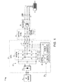
Fig. 1 is a schematic diagram illustrating an exemplary variable frequency drive type power conversion system providing AC output power through a sine wave filter and a step-up transformer and a cable to a driven permanent magnet motor load for submersible pump applications and the like, in which the motor drive inverter output stage is controlled using a current-frequency control component and a reduced bandwidth proportional-integral (PI) control component in accordance with one or more aspects of the present disclosure; -
Fig. 2 is a schematic diagram illustrating further details of the exemplary inverter controller in the system ofFig. 1 , including a rate limiter component, a current-frequency control component, and a reduced bandwidth PI control component in accordance with the disclosure; and -
Fig. 3 is a flow diagram illustrating an exemplary method for controlling a power conversion system driving a load through a filter in accordance with further aspects of the present disclosure. - Referring now to the figures, several embodiments or implementations are hereinafter described in conjunction with the drawings, wherein like reference numerals are used to refer to like elements throughout, and wherein the various features are not necessarily drawn to scale. The present disclosure provides methods and apparatus for driving an electric motor or other load through an output filter and optionally through an additional transformer, and finds utility in submersible pump situations or other applications where an AC load is powered without direct feedback from the driven load. For example, sensorless motor drive applications may be enhanced by use of the disclosed apparatus and methods, even for permanent magnet motor loads, while mitigating or avoiding unregulated drive output current, transformer saturation, and problems with motor starting seen in conventional voltage-frequency sensorless motor drive systems. Accordingly, the advantages of sensorless control can be facilitated, including reduced cost and system complexity, in combination with the use of sine wave filters and transformers to reduce the cost and size of cabling and to mitigate reflected wave problems, while still achieving enhanced control capabilities with respect to motor speed and/or position or other driven load performance parameters. Moreover, the concepts of the present disclosure do not require additional hardware, and thus present a low-cost solution to the above-mentioned problems associated with conventional voltage-frequency sensorless motor control schemes.
-
Fig. 1 illustrates anexemplary system 2 having an AC power source 4 providing three-phase AC input power (e.g., 480 V AC, 50 or 60 Hz) to a motor drivepower conversion system 10. Themotor drive 10, in turn, provides variable frequency, variable amplitude multiphase AC output power through asine wave filter 16 and a connectedtransformer 18, and then through acable 8 to drive a permanent magnet or induction motor load 6 as shown. In various applications, such as submersible pumps, a relativelylengthy cable 8 can be used, and thetransformer 18 may be used in certain implementations as a step-up device to boost the voltage outputs provided by themotor drive 10 to a higher level to combat I2R losses along the length of thecable 8 and reduce the size of thecable 8, and/or to allow a relatively lowvoltage motor drive 10 to operate a higher voltage motor load 6. As seen inFig. 1 , themotor drive 10 includes arectifier 12, which can be an active (e.g., switching) rectifier or a passive rectifier, full wave, half wave, etc., and which receives the AC input power from the source 4 and provides DC power to a bus orDC link circuit 13 having a capacitance C. While illustrated as a multiphase rectifier, the concepts of the present disclosure may be employed in single-phase input drives and power converters. Aninverter 14 receives DC power from thebus circuit 13 and includes switching devices S1, S2, S3, S4, S5 and S6 operated according to inverterswitching control signals 22 provided by acontroller 20 in order to convert the DC power to AC output currents IA, IB and IC for driving the motor load 6. In the illustrated embodiment, theinverter 14 provides a three-phase output, but other multiphase and single-phase output implementations are possible within the scope of the present disclosure. Any suitable inverter switching devices S1-S6 may be used, including without limitation insulated gate bipolar transistors (IGBTs), silicon controlled rectifiers (SCRs), gate turn-off thyristors (GTOs), integrated gate commutated thyristors (IGCTs), etc. - The
motor drive 10 also includes acontroller 20 providing the inverterswitching control signals 22 to the inverter switches S1-S6. Thecontroller 20 and the elements and components thereof (e.g., further shown inFig. 2 below) can include suitable logic or processor-based circuitry, and may also include signal level amplification and/or driver circuitry (not shown) to provide suitable drive voltage and/or current levels sufficient to selectively actuate the switching devices S1-S6, for instance, such as comparators, carrier wave generators or digital logic/processor elements and signal drivers. Moreover, thecontroller 20 can provide theswitching control signals 22 according to any suitable pulse width modulation technique, including without limitation vector modulation (SVM) carrier-based pulse width modulation, selective harmonic elimination (SHE), etc. - The
system 2 ofFig. 1 also includes a sine wave oroutput filter 16, in one example, a three-phase LC filter having a series filter inductor LF in each output line, as well as a corresponding filter capacitor CF coupled between the corresponding phase line and a common connection point. Other output filter topologies may be used, such as LCL filters, CLC filters, etc. with one or more series elements and further filter elements (e.g., filter capacitors CF) connected in any suitable delta or Y configuration. In addition, as shown inFig. 1 , atransformer 18 is provided between thefilter 16 and themotor cable 8. In the illustrated example, thetransformer 18 has a three phase delta-connected primary as well as a Y-connected secondary, although any suitable transformer primary and/or secondary winding configuration or topology may be used. Moreover, thetransformer 18 may, but need not, be a step-up transformer. In certain applications, a step-up transformer 18 is advantageous, for example, to allow a low-voltage drive 10 to power a medium or high voltage motor 6, or to allow use of a medium-voltage drive 10 to power a high-voltage motor 6. Also or in combination, a step-up transformer 18 may be useful to allow a reduction in the current levels carried by thecable 8, thereby facilitating use of smaller diameter cable wires and a corresponding reduction in I2R losses in thecable 8. Thecable 8, moreover, can be of any suitable construction for interfacing the motor drive output, thesine wave filter 16, and thetransformer 18 with the leads of the motor 6. - The
motor drive 10 and thecontroller 20 thereof, operate in sensorless fashion to control one or more operating parameters of the driven motor load 6. For example, thecontroller 20 provides the inverterswitching control signals 22 in order to control position and/or speed and/or torque of the motor 6 without directly sensing any of these controlled parameters. In the illustrated implementation, for instance,current sensors 27 are provided at the output of theinverter 14 to provide feedback signals orvalues 28 to thecontroller 20 which represent the inverter output currents IA, IB and IC, and/or from which the values of these output currents can be computed, derived or otherwise estimated. Any suitablecurrent sensing devices 27 can be used to generate the signals and/orvalues 28, and may provideanalog signals 28 and/or thesensors 27 may be smart sensors providingdigital values 28 representing the output currents IA, IB and IC provided by theinverter 14. - The
controller 20 uses the feedback signals orvalues 28 as well as one or more desiredoperating parameters 21 to perform regulation of the output currents IA, IB and IC in a localized closed-loop fashion. Overall, however, the control technique implemented by thecontroller 20 is essentially sensorless or open-loop with respect to the actual operating condition of the driven motor load 6, as there are no direct feedback signals obtained from the motor 6 itself. In the example ofFig. 1 , for instance, thecontroller 20 receives a desired frequency or motor speed value f* 21 from a supervisory control system component (not shown), which may be a distributed control system element, a user-adjustable knob, local user interface, etc. Thecontroller 20, moreover, includes a current-frequency control component 24 as well as a reduced bandwidth proportional-integral (PI)controller 26 as described further below. In operation, thecontrol components switching control signals 22 according to the desired speed or frequency signal orvalue 21 and the feedback signals or values 28. - Referring also to
Fig. 2 , one embodiment of thecontroller 20 is illustrated, which may optionally include arate limiter 30, as well as the current-frequency (I-F)control component 24 and thePI controller element 26 in a forward control loop path. If included, therate limiter component 30 receives the desired frequency orspeed value 21 and limits the rate of change thereof to provide a frequency orspeed setpoint value 31 as an input to the current-frequency control component 24. Other embodiments are possible in which therate limiter 30 is omitted, with the current-frequency component 24 directly receiving the desired frequency orspeed signal 21 as a setpoint input. In the illustrated implementation, the output signal or value from therate limiter 30 is a rate-limited frequency or speed setpoint signal or value 31 (e.g., f RL), and therate limiter component 30 can be any suitable hardware, processor-executed software, processor-executed firmware, programmable logic, analog circuitry, etc. which limits the rate of change of the received desired speed orfrequency signal 21. - In one possible implementation, for instance, the
rate limiter 30 limits the rate of change of thespeed signal 21 such that theoutput signal 31 is at a frequency which changes no faster than the maximum acceleration capability of the motor 6. For example, thesine wave filter 16 may have a resonant frequency (determined according to the inductance of the filter inductors LF and the capacitance of the filter capacitors CF) of several thousand Hz (e.g., about 4000 Hz in one example), with therate limiter 30 operating to limit the rate of change of the receivedsignal 21 to a few tens of cycles per second (e.g., about 20-30 Hz or less in one embodiment). In operation, a step change in the receivedsignal 21 will be changed to aramp signal 31, and thus therate limiter 30 prevents the subsequent current-frequency control component 24 from demanding an immediate change to high frequency current. Particularly when used with an outputsine wave filter 16 and/or atransformer 18, an immediate change to high frequency current output may not cause the motor load 6 to rotate. Use of therate limiter 30 in certain embodiments advantageously limits the rate of change of the frequency setpoint down to the value where the motor load 6 can accelerate at the desired rate. - The rate limited frequency or
speed setpoint value 31 is provided as an input to the current-frequency control component 24 as well as to anintegration system control component 24 receives the rate-limited frequency orspeed setpoint 31, and generates a δ-axis current setpoint (i*δ) 32 accordingly. As depicted inFig. 2 , thecontroller 20 implements various components, for example, in processor-executed software or firmware, and operates on certain variables in a synchronous δ, γ reference frame, with received feedback signals orvalues 28 and generated switchingcontrol signals 22 being reference to a stationary (e.g., a, b, c) reference frame. In this regard, the illustrated δ, γ reference frame rotates at the same frequency as the conventional field commutation control (D, Q) reference frame, but the position need not be the same, with γ and δ somewhat analogous to "d" and "q", but they are not necessarily aligned (e.g., γ will likely be somewhere between the D axis and the Q axis, and γ and δ are orthogonal to one another). It is also understood that current regulation can be performed in other reference frames. - As seen in
Fig. 2 , the current-frequency control component 24 provides acurrent setpoint output 32 based on the received (e.g., rate-limited) frequency or speed setpoint signal orvalue 31. In one possible implementation, the current-frequency control component 24 implements a dual-range curve or function as illustrated, with the current-frequency relationship being a zero current value corresponding to a zero frequency value (e.g., 0 Hz). As shown inFig. 2 , the current-frequency relationship implemented by thecontrol component 24 includes a first portion with increasing current values corresponding to a first frequency range from the zero frequency value to a cutoff frequency value FCUT, as well as a second portion with a constant current value (e.g., IMAX) corresponding to frequencies above the cutoff frequency FCUT, where IMAX can be the maximum rated output current of theinverter 14 in certain implementations, and the cutoff frequency FCUT is preferably set to correspond to a very low operating frequency of the motor 6 (e.g., about 0.5 - 1.0 Hz in one implementation). The current-frequency control component 24 in certain embodiments can be implemented using a lookup table or a parametric function. In this regard, the current-frequency relationship advantageously avoids providing current to thetransformer 18 and the motor 6 at zero frequency, and includes the first ramped portion until the cutoff frequency, after which the maximum current is demanded, whereby thecontrol component 24 avoids sending DC to thetransformer 18. TheI-F control component 24 thus avoids sending DC to thetransformer 18, and the motor load 6 is typically operated at the maximum current IMAX, whereby the operation of themotor drive 10 is very different from the conventional voltage-frequency approach of prior sensorless drives. - The output (i*δ) of the current-
frequency controller 24 is the δ axiscurrent setpoint 32, which is provided to thePI control component 26. PI control is not a strict requirement of all embodiments of the present disclosure, wherein any suitable current regulating algorithm can be used to regulate the inverter output currents IA, IB and IC at an algorithm bandwidth that is less than the resonant frequency of thesine wave filter 16. In the illustrated embodiment, thePI controller 26 operates according to a zero γ axis value 33 (i* γ = 0), although not a strict requirement of all implementations of the present disclosure. ThePI controller 26 can be any suitable implementation of well-known proportional-integral control algorithms, but the control algorithm is bandwidth limited. Also, thecontrol component 26 can be a PID controller with the corresponding derivative gain (KD) set to zero. The inventors have appreciated that limiting the bandwidth of thePI controller 26 avoids or mitigates large inrush current during power up, particularly where thedrive 10 is providing output currents through asine wave filter 16 and/ortransformer 18. In certain applications, for instance, thesine wave filter 16 makes the inverter output particularly susceptible to large inrush currents, and limiting the bandwidth of the PI controller 26 (or other current regulation control algorithm implemented by the controller 20) to be well below the sine wave filter resonant frequency helps to mitigate or avoid high inrush current levels, particularly at power up. - The reduced
bandwidth PI controller 26 also receives feedback from the output of theinverter 14 from on-board outputcurrent sensors 27. The illustratedcontroller 20 includes a stationary-to-synchronous reference frame converter component 44 (a,b,c --> δ,γ) which provides δ and γ current feedback values 46 and 48 (i δ and i γ), converted from the sensed inverter output phase currents IA, IB and IC as inputs to thePI controller 26. Theconverter 44, moreover, performs the reference frame conversion according to a phase angle signal orvalue θ 43, which is computed in the illustrated embodiment based on the rate limited frequency or speed setpoint signal orvalue 31 as the integral of the frequency ω (2Π * f RL) via amultiplier component 40 generating thefrequency signal ω 41 and anintegrator component 42 providing the phase angle signal orvalue θ 43. ThePI controller 26, moreover, provides δ and γ axis voltage setpoint signal or value outputs Vδ andV value θ 43. Thereference frame converter 36, in turn, provides a set of three stationary reference frame voltage setpoint signals or values 37 (Va , Vb and Vc ) as inputs to a pulse width modulation (PWM)component 38 that includes any suitable form of modulation, isolation, amplifiers, driver circuitry, etc. to generate the inverterswitching control signals 22 using known techniques. - In certain embodiments, the bandwidth of the PI or other regulation control algorithm implemented in the
control component 26 is well below the resonant frequency of the associatedsine wave filter 16. In this regard, conventional servo and/or motor drive control algorithms regulate current using a relatively high bandwidth, such as on the order of 1 kHz. However, as mentioned above, such high control algorithm bandwidth may lead to instability or inability to properly control the output currents provided to the motor load 6, and/or lead to undesirable saturation of thetransformer 18 and excessive inrush current problems. In accordance with the present disclosure, the bandwidth of thePI controller 26 is preferably one or more orders of magnitude lower than the resonant frequency of thesine wave filter 16. For example, thePI controller bandwidth 26 may be on the order of about 20 Hz or 30 Hz for use in association with sine wave filters 16 having a resonant frequency of about 2 kHz to 6 kHz. This can be implemented, for example, by limiting the proportional and integral gains (e.g., KP and KI) used in the regulation algorithm of thePI controller 26. The output of thePI controller 26 in this regard may be implemented as the summation of the error between the current setpoint values 32 and 33 and the corresponding feedback values 46 and 48, multiplied by the proportional constant KP added to the integral of the error multiplied by the integral constant KI. Thus in specific embodiments, the current loop regulation bandwidth is significantly below the resonant range of thefilter 16, and this can be implemented by suitable caps or limits on the KI and the KP values used in thePI algorithm 26 such that the resonant point of the entire closed loop is less than about 20 or 30 Hz in certain implementations. Thus, the current regulation algorithm implemented by thecontroller 20 will not attempt to regulate current above about 30 Hz. Theoutput PI controller 26 is the synchronous reference frame voltage values 34 and 35, which are then translated into the three-phase stationary reference frame values 37 that are used for pulse width modulating the inverter switches S1-S6. - Referring also to
Fig. 3 , a flow diagram is provided illustrating amethod 100 for controlling a power conversion system (e.g., themotor drive 10 above) to drive a load (e.g., motor 6) through a filter (e.g., sine wave filter 16). Although theexemplary method 100 is depicted and described in the form of a series of acts or events, it will be appreciated that the various methods of the disclosure are not limited by the illustrated ordering of such acts or events except as specifically set forth herein. In this regard, except as specifically provided hereinafter, some acts or events may occur in different order and/or concurrently with other acts or events apart from those illustrated and described herein, and not all illustrated steps may be required to implement a process or method in accordance with the present disclosure. The illustrated methods may be implemented in hardware, processor-executed software, or combinations thereof, in order to provide sensorless motor control using bandwidth limited control algorithms as described herein, and various embodiments or implementations include non-transitory computer readable mediums having computer-executable instructions performing the illustrated and described methods. For instance, themethod 100 may be implemented using one or more processors associated with thecontroller 20, by executing instructions stored in an electronic memory operatively associated with thecontroller 20. - The
process 100 begins at 102 where an updated desired frequency or speed value is received (e.g., signal or value f* 21 inFigs. 1 and2 above). At 104, the desired value f* may optionally be rate limited to provide a rate limited frequency or speed setpoint value (e.g.,f RL 31 inFig. 2 ). At 106 inFig. 3 , a current setpoint value is determined (δ-axis current setpoint i* δ 32 inFig. 2 ) at least partially according to the frequency orspeed setpoint value sensors 27 inFig. 1 above). At 110, the AC output current(s) is/are regulated according to thecurrent setpoint value 32 and the feedback signal(s) or value(s) 28 using a control algorithm having a bandwidth below the resonant frequency of thefilter 16. For instance, the AC output currents are regulated in the above describedmotor drive 10 using a proportional-integral control algorithm (e.g., via PI controller 26) having a bandwidth that is less than the resonant frequency of thesine wave filter 16. Theprocess 100 inFig. 3 then returns to receive another updated desired frequency orspeed value 21 at 102 and continues as described above. - The above techniques and apparatus thus advantageously facilitate sensorless control of induction or permanent magnet motor loads 6 in applications such as those described supra in which sine wave filters 16 and/or
transformers 18 are provided to accommodatelong cable lengths 8 without the shortcomings associated with conventional voltage-frequency control schemes. In addition, the disclosed concepts can be employed without any additional hardware, and may be implemented largely in processor-executed software of amotor drive controller 20. These techniques, moreover, may be employed to reduce or avoid filter inrush current, transformer saturation, and uncontrolled motor drive output current oscillation associated with conventional approaches, while avoiding extra cost and/or system complexity associated with provision of sensors at the load 6. In addition, the techniques also allow the system design flexibility of employingtransformers 18 to accommodate long cable runs while reducing or avoiding I2R losses and allowing the use ofsmaller cabling 8, thereby providing viable solutions to submersible pump applications and other installations where thetransformer 18 can accommodate use of low-voltage motor drives 10 for medium or higher voltage motors 6, including permanent magnet motors. - The above examples are merely illustrative of several possible embodiments of various aspects of the present disclosure, wherein equivalent alterations and/or modifications will occur to others skilled in the art upon reading and understanding this specification and the annexed drawings. In particular regard to the various functions performed by the above described components (assemblies, devices, systems, circuits, and the like), the terms (including a reference to a "means") used to describe such components are intended to correspond, unless otherwise indicated, to any component, such as hardware, processor-executed software, or combinations thereof, which performs the specified function of the described component (i.e., that is functionally equivalent), even though not structurally equivalent to the disclosed structure which performs the function in the illustrated implementations of the disclosure. In addition, although a particular feature of the disclosure may have been disclosed with respect to only one of several implementations, such feature may be combined with one or more other features of the other implementations as may be desired and advantageous for any given or particular application. Also, to the extent that the terms "including", "includes", "having", "has", "with", or variants thereof are used in the detailed description and/or in the claims, such terms are intended to be inclusive in a manner similar to the term "comprising".
-
-
Embodiment 1. A power conversion system, comprising:- an inverter including a plurality of switching devices operable according to switching control signals to provide AC output power to drive a load; and
- a controller providing the switching control signals to the inverter to regulate the inverter output currents at least partially according to a frequency or speed setpoint value via a control algorithm having a bandwidth below a resonant frequency of a filter coupled between the inverter and the load.
-
Embodiment 2. The power conversion system ofembodiment 1, wherein the controller comprises:- a current-frequency control component providing a current setpoint value according to the frequency or speed setpoint value; and
- a current control regulator component implementing the control algorithm to regulate the inverter output currents at least partially according to the current setpoint value.
-
Embodiment 3. The power conversion system ofembodiment 2, wherein the current control regulator component is a proportional-integral controller having a bandwidth below the resonant frequency of the filter coupled between the inverter and the load. - Embodiment 4. The power conversion system of
embodiment 3, wherein the current control regulator component implements the control algorithm to regulate the inverter output currents according to the current setpoint value and at least one feedback signal or value representing the inverter output currents. -
Embodiment 5. The power conversion system of embodiment 4, wherein the controller comprises a rate limiter component limiting a rate of change of a received desired frequency or speed value to provide the frequency or speed setpoint value. - Embodiment 6. The power conversion system of
embodiment 3, wherein the controller comprises a rate limiter component limiting a rate of change of a received desired frequency or speed value to provide the frequency or speed setpoint value. - Embodiment 7. The power conversion system of
embodiment 2, wherein the current control regulator component implements the control algorithm to regulate the inverter output currents according to the current setpoint value and at least one feedback signal or value representing the inverter output currents. -
Embodiment 8. The power conversion system of embodiment 7, wherein the controller comprises a rate limiter component limiting a rate of change of a received desired frequency or speed value to provide the frequency or speed setpoint value. - Embodiment 9. The power conversion system of
embodiment 2, wherein the controller comprises a rate limiter component limiting a rate of change of a received desired frequency or speed value to provide the frequency or speed setpoint value. -
Embodiment 10. The power conversion system ofembodiment 2, wherein the controller includes a proportional-integral controller to regulate the inverter output currents, the proportional-integral controller having a bandwidth below the resonant frequency of the filter coupled between the inverter and the load. - Embodiment 11. The power conversion system of
embodiment 10, wherein the controller regulates the inverter output currents according to a current setpoint value derived from the frequency or speed setpoint value and according to at least one feedback signal or value representing the inverter output currents. -
Embodiment 12. The power conversion system ofembodiment 10, wherein the controller comprises a rate limiter component limiting a rate of change of a received desired frequency or speed value to provide the frequency or speed setpoint value. -
Embodiment 13. The power conversion system ofembodiment 1, wherein the controller regulates the inverter output currents according to a current setpoint value derived from the frequency or speed setpoint value and according to at least one feedback signal or value representing the inverter output currents. -
Embodiment 14. The power conversion system ofembodiment 1, wherein the controller comprises a rate limiter component limiting a rate of change of a received desired frequency or speed value to provide the frequency or speed setpoint value. - Embodiment 15. A method for controlling a power conversion system driving a load through a filter, the method comprising:
- determining a current setpoint value at least partially according to a frequency or speed setpoint value;
- sampling at least one AC output current feedback signal or value of the power conversion system; and
- regulating the at least one AC output current according to the current setpoint value and the at least one AC output current feedback signal or value using a control algorithm having a bandwidth below a resonant frequency of the filter.
-
Embodiment 16. The method of embodiment 15, comprising limiting a rate of change of a desired frequency or speed value to determine the frequency or speed setpoint value. - Embodiment 17. The method of embodiment 15, wherein the current setpoint value is determined according to a current-frequency relationship with a zero current value corresponding to a zero frequency value.
-
Embodiment 18. The method of embodiment 17, wherein the current-frequency relationship includes a first portion with increasing current values corresponding to a first frequency range from the zero frequency value to a cutoff frequency value, and a second portion with a constant current value corresponding to frequencies higher than the cutoff frequency value. - Embodiment 19. The method of embodiment 15, wherein the at least one AC output current is regulated using a proportional-integral control algorithm having a bandwidth below the resonant frequency of the filter.
-
Embodiment 20. A computer readable medium with computer executable instructions for controlling a power conversion system driving a load through a filter, the computer readable medium comprising computer executable instructions for:- determining a current setpoint value at least partially according to a frequency or speed setpoint value;
- sampling at least one AC output current feedback signal or value of the power conversion system; and
- regulating the at least one AC output current according to the current setpoint value and the at least one AC output current feedback signal or value using a control algorithm having a bandwidth below a resonant frequency of the filter.
| S1-S6 | switching devices |
| IA, IB, IC | |
| 2 | system |
| 4 | AC power source |
| 6 | induction motor load/ |
| 8 | |
| 10 | motor drive |
| 12 | |
| 13 | |
| 14 | |
| 16 | |
| 18 | |
| 20 | |
| 21 | |
| 22 | inverter |
| 24 | current- |
| 26 | bandwidth proportional-integral (PI) |
| 27 | |
| 28 | feedback signals |
| 30 | |
| 31 | |
| 32 | δ- |
| 33 | zero |
| 34, 35 | synchronous reference frame voltage values |
| 36 | |
| 37 | reference frame voltage setpoint signals |
| 40, 42 | |
| 43 | |
| 44 | |
| 46, 48 | δ and γ current feedback values |
| 100 | |
| 102, 104, 106, 108, 110 | steps |
Claims (10)
- A power conversion system (10), comprising:an inverter (14) including a plurality of switching devices (S1-S6) operable according to switching control signals (22) to provide AC output power to drive a load (6); anda controller (20) providing the switching control signals (22) to the inverter (14) to regulate the inverter output currents (IA, IB, IC) at least partially according to a frequency or speed setpoint value (21, 31) via a control algorithm (26) having a bandwidth below a resonant frequency of a filter (16) coupled between the inverter (14) and the load (6).
- The power conversion system (10) of claim 1, wherein the controller (20) comprises:a current-frequency control component (24) providing a current setpoint value (32) according to the frequency or speed setpoint value (21, 31); anda current control regulator component (26) implementing the control algorithm to regulate the inverter output currents (IA, IB, IC) at least partially according to the current setpoint value (32).
- The power conversion system (10) of claim 2, wherein the controller (20) comprises a rate limiter component (30) limiting a rate of change of a received desired frequency or speed value (21) to provide the frequency or speed setpoint value (31).
- The power conversion system (10) of claim 1, wherein the controller (20) includes a proportional-integral (PI) controller (26) to regulate the inverter output currents (IA, IB, IC), the proportional-integral (PI) controller (26) having a bandwidth below the resonant frequency of the filter (16) coupled between the inverter (14) and the load (6).
- The power conversion system (10) of claim 4, wherein the controller (20) comprises a rate limiter component (30) limiting a rate of change of a received desired frequency or speed value (21) to provide the frequency or speed setpoint value (31).
- The power conversion system (10) of claim 1, wherein the controller (20) regulates the inverter output currents (IA, IB, IC) according to a current setpoint value (32) derived from the frequency or speed setpoint value (21, 31) and according to at least one feedback signal or value (46, 48) representing the inverter output currents (IA, IB, IC),
- The power conversion system (10) of claim 1, wherein the controller (20) comprises a rate limiter component (30) limiting a rate of change of a received desired frequency or speed value (21) to provide the frequency or speed setpoint value (31).
- A method (100) for controlling a power conversion system (10) driving a load (6) through a filter (16), the method (100) comprising:determining a current setpoint value (32) at least partially according to a frequency or speed setpoint value (21, 31);sampling at least one AC output current feedback signal or value (IA, IB, IC) of the power conversion system (10); andregulating the at least one AC output current (IA, IB, IC) according to the current setpoint value (32) and the at least one AC output current feedback signal or value (IA, IB, IC) using a control algorithm (26) having a bandwidth below a resonant frequency of the filter (16).
- The method (100) of claim 8, comprising limiting a rate of change of a desired frequency or speed value (21) to determine the frequency or speed setpoint value (31).
- The method (100) of claim 8, wherein the at least one AC output current (IA, IB, IC) is regulated using a proportional-integral control algorithm (26) having a bandwidth below the resonant frequency of the filter (16).
Applications Claiming Priority (1)
| Application Number | Priority Date | Filing Date | Title |
|---|---|---|---|
| US13/868,216 US9054621B2 (en) | 2013-04-23 | 2013-04-23 | Position sensorless open loop control for motor drives with output filter and transformer |
Publications (3)
| Publication Number | Publication Date |
|---|---|
| EP2797220A1 true EP2797220A1 (en) | 2014-10-29 |
| EP2797220A3 EP2797220A3 (en) | 2015-03-25 |
| EP2797220B1 EP2797220B1 (en) | 2020-02-19 |
Family
ID=50771400
Family Applications (1)
| Application Number | Title | Priority Date | Filing Date |
|---|---|---|---|
| EP14165682.7A Active EP2797220B1 (en) | 2013-04-23 | 2014-04-23 | Position sensorless open loop control for motor drives with output filter and transformer |
Country Status (4)
| Country | Link |
|---|---|
| US (2) | US9054621B2 (en) |
| EP (1) | EP2797220B1 (en) |
| CN (1) | CN104124883B (en) |
| BR (1) | BR102014009688B1 (en) |
Families Citing this family (29)
| Publication number | Priority date | Publication date | Assignee | Title |
|---|---|---|---|---|
| US9294019B2 (en) | 2013-01-16 | 2016-03-22 | Rockwell Automation Technologies, Inc. | Method and apparatus for controlling power converter with inverter output filter |
| US9490738B2 (en) | 2013-01-16 | 2016-11-08 | Rockwell Automation Technologies, Inc. | Sensorless motor drive vector control |
| US10158314B2 (en) | 2013-01-16 | 2018-12-18 | Rockwell Automation Technologies, Inc. | Feedforward control of motor drives with output sinewave filter |
| US9054621B2 (en) | 2013-04-23 | 2015-06-09 | Rockwell Automation Technologies, Inc. | Position sensorless open loop control for motor drives with output filter and transformer |
| JP6303354B2 (en) * | 2013-09-19 | 2018-04-04 | 株式会社デンソー | Motor drive device |
| US9374028B2 (en) | 2014-08-22 | 2016-06-21 | Rockwell Automation Technologies, Inc. | Transition scheme for position sensorless control of AC motor drives |
| US9716460B2 (en) | 2015-01-28 | 2017-07-25 | Rockwell Automation Technologies, Inc. | Method and apparatus for speed reversal control of motor drive |
| US9774284B2 (en) | 2015-02-19 | 2017-09-26 | Rockwell Automation Technologies, Inc. | Rotor position estimation apparatus and methods |
| US9595903B2 (en) * | 2015-03-20 | 2017-03-14 | General Electric Company | Controller for motor |
| FR3047134A1 (en) * | 2016-01-26 | 2017-07-28 | Valeo Systemes Thermiques | SPECTRAL SPACER FOR ELECTRIC MOTOR |
| US9800190B2 (en) * | 2016-02-03 | 2017-10-24 | Rockwell Automation Technologies, Inc. | Control of motor drives with output sinewave filter capacitor current compensation using sinewave filter transfer function |
| US9985565B2 (en) | 2016-04-18 | 2018-05-29 | Rockwell Automation Technologies, Inc. | Sensorless motor drive vector control with feedback compensation for filter capacitor current |
| US10020766B2 (en) | 2016-11-15 | 2018-07-10 | Rockwell Automation Technologies, Inc. | Current control of motor drives with output sinewave filter |
| US10528023B2 (en) | 2016-12-22 | 2020-01-07 | General Dynamics-OTS. Inc. | Electric motor drive system for low-voltage motor |
| WO2019020185A1 (en) | 2017-07-27 | 2019-01-31 | Vacon Oy | Motor drive adaptation |
| FR3075512B1 (en) * | 2017-12-19 | 2019-11-08 | Schneider Toshiba Inverter Europe Sas | METHOD FOR CONTROLLING AN ELECTRIC MOTOR INCLUDING AN IDENTIFICATION SEQUENCE OF A TRANSFORMER |
| CN108429285A (en) * | 2018-03-29 | 2018-08-21 | 武汉理工大学 | It is a kind of to be suitable for the peculiar to vessel from the two-way frequency-changing and current transforming device of grid-connected mixed type of kHz grades of alternating currents |
| CN109546781A (en) * | 2018-10-09 | 2019-03-29 | 武汉船用电力推进装置研究所(中国船舶重工集团公司第七二研究所) | A kind of high-performance permanent magnet propulsion system topology |
| US11057029B2 (en) * | 2019-11-25 | 2021-07-06 | Silicon Laboratories Inc. | Gate driver with integrated miller clamp |
| US10917081B1 (en) | 2020-03-11 | 2021-02-09 | Silicon Laboratories Inc. | Adjustable soft shutdown and current booster for gate driver |
| CN113572368B (en) * | 2020-04-28 | 2022-10-21 | 元宏国际股份有限公司 | Medium-high power frequency-adjustable digital power supply system |
| US11108335B1 (en) * | 2020-05-06 | 2021-08-31 | Elementech International Co., Ltd. | Medium- and high-power frequency-adjustable digital power system |
| US11752958B2 (en) * | 2020-05-28 | 2023-09-12 | Transportation Ip Holdings, Llc | Systems and methods for providing power to sensors |
| US11362646B1 (en) | 2020-12-04 | 2022-06-14 | Skyworks Solutions, Inc. | Variable current drive for isolated gate drivers |
| US12155332B2 (en) | 2020-12-06 | 2024-11-26 | Skyworks Solutions, Inc. | Updating control parameters of a gate driver during operation |
| US11641197B2 (en) | 2021-04-28 | 2023-05-02 | Skyworks Solutions, Inc. | Gate driver output protection circuit |
| CN113364318B (en) * | 2021-06-15 | 2024-01-26 | 昱能科技股份有限公司 | Output control method, device, equipment and medium for inverter driving inductive load |
| US12345144B2 (en) * | 2022-03-11 | 2025-07-01 | Caterpillar Inc. | Automatically controlling a power ramp rate of a motor of a pump system |
| CN115296590A (en) * | 2022-09-05 | 2022-11-04 | 山东双益电气有限责任公司 | Control power supply of electric submersible pump |
Citations (2)
| Publication number | Priority date | Publication date | Assignee | Title |
|---|---|---|---|---|
| EP1635448A1 (en) * | 2004-09-09 | 2006-03-15 | ABB Oy | Speed sensorless control of an induction machine using a PWM inverter with output LC filter |
| US20070007929A1 (en) * | 2005-07-07 | 2007-01-11 | Kevin Lee | System and method of controlling power to a non-motor load |
Family Cites Families (33)
| Publication number | Priority date | Publication date | Assignee | Title |
|---|---|---|---|---|
| US3723840A (en) | 1972-01-21 | 1973-03-27 | Power Control Corp | Apparatus for motor current minimization |
| JPH0746917B2 (en) | 1987-07-28 | 1995-05-17 | 三菱電機株式会社 | Control device for three-phase converter |
| US5909098A (en) * | 1996-05-02 | 1999-06-01 | Reda Pump | Downhole pumping system with variable speed pulse-width modulated inverter coupled to electrical motor via non-gap transformer |
| US5744921A (en) | 1996-05-02 | 1998-04-28 | Siemens Electric Limited | Control circuit for five-phase brushless DC motor |
| US6124697A (en) | 1997-08-20 | 2000-09-26 | Wilkerson; Alan W. | AC inverter drive |
| US5959431A (en) | 1997-10-03 | 1999-09-28 | Baldor Electric Company | Method and apparatus for instability compensation of V/Hz pulse width modulation inverter-fed induction motor drives |
| US5994869A (en) | 1997-12-05 | 1999-11-30 | General Electric Company | Power conversion circuit for a motor |
| US6121736A (en) | 1998-07-10 | 2000-09-19 | Matsushita Electric Industrial Co., Ltd. | Control apparatus for motor, and motor unit having the control apparatus |
| JP3396440B2 (en) | 1999-02-08 | 2003-04-14 | 株式会社日立製作所 | Control device for synchronous motor |
| JP3483805B2 (en) | 1999-07-05 | 2004-01-06 | 株式会社東芝 | Step-out detection device for sensorless brushless motor |
| US6208537B1 (en) * | 1999-09-28 | 2001-03-27 | Rockwell Technologies, Llc | Series resonant sinewave output filter and design methodology |
| CN2513286Y (en) | 2001-11-01 | 2002-09-25 | 哈尔滨工业大学 | Adjustable filter for converter output |
| JP4370754B2 (en) | 2002-04-02 | 2009-11-25 | 株式会社安川電機 | Sensorless control device and control method for AC motor |
| JP4112930B2 (en) | 2002-09-04 | 2008-07-02 | 東芝三菱電機産業システム株式会社 | Inverter device |
| US7102323B2 (en) | 2004-11-30 | 2006-09-05 | Honeywell International Inc. | High power density/limited DC link voltage synchronous motor drive |
| JP4895703B2 (en) | 2006-06-28 | 2012-03-14 | 三洋電機株式会社 | Motor control device |
| US7724549B2 (en) * | 2006-09-22 | 2010-05-25 | Rockwell Automation Technologies, Inc. | Integrated power conditioning system and housing for delivering operational power to a motor |
| JP5239235B2 (en) | 2006-10-13 | 2013-07-17 | 日産自動車株式会社 | Power conversion device and power conversion method |
| US7979223B2 (en) * | 2007-06-15 | 2011-07-12 | University Of South Carolina | Systems and methods for power hardware in the loop testing |
| JP5130031B2 (en) | 2007-12-10 | 2013-01-30 | 株式会社日立製作所 | Position sensorless control device for permanent magnet motor |
| ITBO20080047A1 (en) | 2008-01-25 | 2009-07-26 | Spal Automotive Srl | ELECTRIC DRIVE AND PILOT METHOD OF THE SAME. |
| KR101244588B1 (en) * | 2008-04-28 | 2013-04-01 | 다이킨 고교 가부시키가이샤 | Inverter control device and power conversion device |
| US8009450B2 (en) | 2008-08-26 | 2011-08-30 | Rockwell Automation Technologies, Inc. | Method and apparatus for phase current balance in active converter with unbalanced AC line voltage source |
| US7990097B2 (en) | 2008-09-29 | 2011-08-02 | Rockwell Automation Technologies, Inc. | Power conversion system and method for active damping of common mode resonance |
| CN201504207U (en) | 2009-08-20 | 2010-06-09 | 中冶南方(武汉)自动化有限公司 | An AC drive system with energy feedback |
| US8174222B2 (en) * | 2009-10-12 | 2012-05-08 | GM Global Technology Operations LLC | Methods, systems and apparatus for dynamically controlling an electric motor that drives an oil pump |
| US8288886B2 (en) * | 2009-11-09 | 2012-10-16 | GM Global Technology Operations LLC | Method and apparatus for avoiding electrical resonance in a vehicle having a shared high-voltage bus |
| CN101950983A (en) | 2010-10-08 | 2011-01-19 | 天津理工大学 | Two-stage photovoltaic grid-connected control system based on combination of pole allocation and repetitive control |
| CN202872721U (en) * | 2011-12-01 | 2013-04-10 | 国电南京自动化股份有限公司 | Vector control system free of speed sensor and based on cascade high voltage frequency converter |
| US9287812B2 (en) | 2013-06-29 | 2016-03-15 | Rockwell Automation Technologies, Inc. | Method and apparatus for stability control of open loop motor drive operation |
| US9124209B2 (en) | 2013-01-16 | 2015-09-01 | Rockwell Automation Technologies, Inc. | Method and apparatus for controlling power converter with inverter output filter |
| US9054611B2 (en) | 2013-06-29 | 2015-06-09 | Rockwell Automation Technologies, Inc. | Method and apparatus for stability control of open loop motor drive operation |
| US9054621B2 (en) | 2013-04-23 | 2015-06-09 | Rockwell Automation Technologies, Inc. | Position sensorless open loop control for motor drives with output filter and transformer |
-
2013
- 2013-04-23 US US13/868,216 patent/US9054621B2/en active Active
-
2014
- 2014-04-23 EP EP14165682.7A patent/EP2797220B1/en active Active
- 2014-04-23 BR BR102014009688-4A patent/BR102014009688B1/en not_active IP Right Cessation
- 2014-04-23 CN CN201410165847.5A patent/CN104124883B/en not_active Expired - Fee Related
-
2015
- 2015-03-24 US US14/666,894 patent/US9312779B2/en active Active
Patent Citations (2)
| Publication number | Priority date | Publication date | Assignee | Title |
|---|---|---|---|---|
| EP1635448A1 (en) * | 2004-09-09 | 2006-03-15 | ABB Oy | Speed sensorless control of an induction machine using a PWM inverter with output LC filter |
| US20070007929A1 (en) * | 2005-07-07 | 2007-01-11 | Kevin Lee | System and method of controlling power to a non-motor load |
Non-Patent Citations (2)
| Title |
|---|
| OSMAN KUKRER: "Deadbeat Control of a Three-Phase Inverter with an Output LC Filter", IEEE TRANSACTIONS ON POWER ELECTRONICS, INSTITUTE OF ELECTRICAL AND ELECTRONICS ENGINEERS, USA, vol. 11, no. 1, 1 January 1996 (1996-01-01), XP011042923, ISSN: 0885-8993 * |
| STEINKE J K ET AL: "Use of a LC filter to achieve a motor friendly performance of the PWM voltage source inverter", ELECTRIC MACHINES AND DRIVES CONFERENCE RECORD, 1997. IEEE INTERNATION AL MILWAUKEE, WI, USA 18-21 MAY 1997, NEW YORK, NY, USA,IEEE, US, 18 May 1997 (1997-05-18), pages TA2/4.1 - TA2/4.3, XP010231763, ISBN: 978-0-7803-3946-0 * |
Also Published As
| Publication number | Publication date |
|---|---|
| CN104124883B (en) | 2017-11-07 |
| EP2797220A3 (en) | 2015-03-25 |
| BR102014009688B1 (en) | 2021-03-16 |
| US9312779B2 (en) | 2016-04-12 |
| US20150194901A1 (en) | 2015-07-09 |
| EP2797220B1 (en) | 2020-02-19 |
| US9054621B2 (en) | 2015-06-09 |
| US20140312811A1 (en) | 2014-10-23 |
| CN104124883A (en) | 2014-10-29 |
Similar Documents
| Publication | Publication Date | Title |
|---|---|---|
| US9054621B2 (en) | Position sensorless open loop control for motor drives with output filter and transformer | |
| US9374028B2 (en) | Transition scheme for position sensorless control of AC motor drives | |
| US9287812B2 (en) | Method and apparatus for stability control of open loop motor drive operation | |
| US9054611B2 (en) | Method and apparatus for stability control of open loop motor drive operation | |
| US9240733B2 (en) | High dynamic control apparatus for current source converter | |
| EP3054584B1 (en) | Method and apparatus for speed reversal control of motor drive | |
| US9490738B2 (en) | Sensorless motor drive vector control | |
| EP2043241A2 (en) | Motor Drive Using Flux Adjustment to Control Power Factor | |
| US9985565B2 (en) | Sensorless motor drive vector control with feedback compensation for filter capacitor current | |
| US20160173012A1 (en) | Sensorless motor drive vector control with feedback compensation for filter capacitor current | |
| US11424707B2 (en) | Power conversion apparatus | |
| EP3136586B1 (en) | Sensorless motor drive vector control with feedback compensation for filter capacitor current | |
| US9800190B2 (en) | Control of motor drives with output sinewave filter capacitor current compensation using sinewave filter transfer function | |
| WO2016035434A1 (en) | Motor drive device | |
| JP6513564B2 (en) | Inverter device capable of resonance avoidance | |
| JP2016052142A (en) | Motor control device | |
| CN120675396A (en) | Inverter circuit control method and power conversion equipment | |
| KR20170122050A (en) | Voltage compensation method for motor control inverter | |
| BR102014009688A2 (en) | ENERGY CONVERSION SYSTEM AND METHOD FOR CONTROLLING AN ENERGY CONVERSION SYSTEM |
Legal Events
| Date | Code | Title | Description |
|---|---|---|---|
| PUAI | Public reference made under article 153(3) epc to a published international application that has entered the european phase |
Free format text: ORIGINAL CODE: 0009012 |
|
| 17P | Request for examination filed |
Effective date: 20140423 |
|
| AK | Designated contracting states |
Kind code of ref document: A1 Designated state(s): AL AT BE BG CH CY CZ DE DK EE ES FI FR GB GR HR HU IE IS IT LI LT LU LV MC MK MT NL NO PL PT RO RS SE SI SK SM TR |
|
| AX | Request for extension of the european patent |
Extension state: BA ME |
|
| PUAB | Information related to the publication of an a document modified or deleted |
Free format text: ORIGINAL CODE: 0009199EPPU |
|
| PUAF | Information related to the publication of a search report (a3 document) modified or deleted |
Free format text: ORIGINAL CODE: 0009199SEPU |
|
| PUAL | Search report despatched |
Free format text: ORIGINAL CODE: 0009013 |
|
| D17D | Deferred search report published (deleted) | ||
| AK | Designated contracting states |
Kind code of ref document: A3 Designated state(s): AL AT BE BG CH CY CZ DE DK EE ES FI FR GB GR HR HU IE IS IT LI LT LU LV MC MK MT NL NO PL PT RO RS SE SI SK SM TR |
|
| AX | Request for extension of the european patent |
Extension state: BA ME |
|
| RIC1 | Information provided on ipc code assigned before grant |
Ipc: H02P 21/00 20060101AFI20150216BHEP Ipc: H02M 1/12 20060101ALI20150216BHEP |
|
| R17P | Request for examination filed (corrected) |
Effective date: 20150522 |
|
| RBV | Designated contracting states (corrected) |
Designated state(s): AL AT BE BG CH CY CZ DE DK EE ES FI FR GB GR HR HU IE IS IT LI LT LU LV MC MK MT NL NO PL PT RO RS SE SI SK SM TR |
|
| STAA | Information on the status of an ep patent application or granted ep patent |
Free format text: STATUS: EXAMINATION IS IN PROGRESS |
|
| 17Q | First examination report despatched |
Effective date: 20180614 |
|
| GRAJ | Information related to disapproval of communication of intention to grant by the applicant or resumption of examination proceedings by the epo deleted |
Free format text: ORIGINAL CODE: EPIDOSDIGR1 |
|
| STAA | Information on the status of an ep patent application or granted ep patent |
Free format text: STATUS: GRANT OF PATENT IS INTENDED |
|
| GRAP | Despatch of communication of intention to grant a patent |
Free format text: ORIGINAL CODE: EPIDOSNIGR1 |
|
| INTG | Intention to grant announced |
Effective date: 20191008 |
|
| RIN1 | Information on inventor provided before grant (corrected) |
Inventor name: NONDAHL, THOMAS Inventor name: SCHMIDT, PETER Inventor name: LIU, JINGBO Inventor name: ROYAK, SEMYON |
|
| GRAS | Grant fee paid |
Free format text: ORIGINAL CODE: EPIDOSNIGR3 |
|
| GRAA | (expected) grant |
Free format text: ORIGINAL CODE: 0009210 |
|
| STAA | Information on the status of an ep patent application or granted ep patent |
Free format text: STATUS: THE PATENT HAS BEEN GRANTED |
|
| AK | Designated contracting states |
Kind code of ref document: B1 Designated state(s): AL AT BE BG CH CY CZ DE DK EE ES FI FR GB GR HR HU IE IS IT LI LT LU LV MC MK MT NL NO PL PT RO RS SE SI SK SM TR |
|
| REG | Reference to a national code |
Ref country code: CH Ref legal event code: EP |
|
| REG | Reference to a national code |
Ref country code: DE Ref legal event code: R096 Ref document number: 602014061134 Country of ref document: DE |
|
| REG | Reference to a national code |
Ref country code: AT Ref legal event code: REF Ref document number: 1236111 Country of ref document: AT Kind code of ref document: T Effective date: 20200315 |
|
| REG | Reference to a national code |
Ref country code: IE Ref legal event code: FG4D |
|
| REG | Reference to a national code |
Ref country code: NL Ref legal event code: MP Effective date: 20200219 |
|
| PG25 | Lapsed in a contracting state [announced via postgrant information from national office to epo] |
Ref country code: RS Free format text: LAPSE BECAUSE OF FAILURE TO SUBMIT A TRANSLATION OF THE DESCRIPTION OR TO PAY THE FEE WITHIN THE PRESCRIBED TIME-LIMIT Effective date: 20200219 Ref country code: FI Free format text: LAPSE BECAUSE OF FAILURE TO SUBMIT A TRANSLATION OF THE DESCRIPTION OR TO PAY THE FEE WITHIN THE PRESCRIBED TIME-LIMIT Effective date: 20200219 Ref country code: NO Free format text: LAPSE BECAUSE OF FAILURE TO SUBMIT A TRANSLATION OF THE DESCRIPTION OR TO PAY THE FEE WITHIN THE PRESCRIBED TIME-LIMIT Effective date: 20200519 |
|
| REG | Reference to a national code |
Ref country code: LT Ref legal event code: MG4D |
|
| PG25 | Lapsed in a contracting state [announced via postgrant information from national office to epo] |
Ref country code: LV Free format text: LAPSE BECAUSE OF FAILURE TO SUBMIT A TRANSLATION OF THE DESCRIPTION OR TO PAY THE FEE WITHIN THE PRESCRIBED TIME-LIMIT Effective date: 20200219 Ref country code: SE Free format text: LAPSE BECAUSE OF FAILURE TO SUBMIT A TRANSLATION OF THE DESCRIPTION OR TO PAY THE FEE WITHIN THE PRESCRIBED TIME-LIMIT Effective date: 20200219 Ref country code: HR Free format text: LAPSE BECAUSE OF FAILURE TO SUBMIT A TRANSLATION OF THE DESCRIPTION OR TO PAY THE FEE WITHIN THE PRESCRIBED TIME-LIMIT Effective date: 20200219 Ref country code: IS Free format text: LAPSE BECAUSE OF FAILURE TO SUBMIT A TRANSLATION OF THE DESCRIPTION OR TO PAY THE FEE WITHIN THE PRESCRIBED TIME-LIMIT Effective date: 20200619 Ref country code: GR Free format text: LAPSE BECAUSE OF FAILURE TO SUBMIT A TRANSLATION OF THE DESCRIPTION OR TO PAY THE FEE WITHIN THE PRESCRIBED TIME-LIMIT Effective date: 20200520 Ref country code: BG Free format text: LAPSE BECAUSE OF FAILURE TO SUBMIT A TRANSLATION OF THE DESCRIPTION OR TO PAY THE FEE WITHIN THE PRESCRIBED TIME-LIMIT Effective date: 20200519 |
|
| PG25 | Lapsed in a contracting state [announced via postgrant information from national office to epo] |
Ref country code: NL Free format text: LAPSE BECAUSE OF FAILURE TO SUBMIT A TRANSLATION OF THE DESCRIPTION OR TO PAY THE FEE WITHIN THE PRESCRIBED TIME-LIMIT Effective date: 20200219 |
|
| PG25 | Lapsed in a contracting state [announced via postgrant information from national office to epo] |
Ref country code: RO Free format text: LAPSE BECAUSE OF FAILURE TO SUBMIT A TRANSLATION OF THE DESCRIPTION OR TO PAY THE FEE WITHIN THE PRESCRIBED TIME-LIMIT Effective date: 20200219 Ref country code: SK Free format text: LAPSE BECAUSE OF FAILURE TO SUBMIT A TRANSLATION OF THE DESCRIPTION OR TO PAY THE FEE WITHIN THE PRESCRIBED TIME-LIMIT Effective date: 20200219 Ref country code: CZ Free format text: LAPSE BECAUSE OF FAILURE TO SUBMIT A TRANSLATION OF THE DESCRIPTION OR TO PAY THE FEE WITHIN THE PRESCRIBED TIME-LIMIT Effective date: 20200219 Ref country code: PT Free format text: LAPSE BECAUSE OF FAILURE TO SUBMIT A TRANSLATION OF THE DESCRIPTION OR TO PAY THE FEE WITHIN THE PRESCRIBED TIME-LIMIT Effective date: 20200712 Ref country code: SM Free format text: LAPSE BECAUSE OF FAILURE TO SUBMIT A TRANSLATION OF THE DESCRIPTION OR TO PAY THE FEE WITHIN THE PRESCRIBED TIME-LIMIT Effective date: 20200219 Ref country code: EE Free format text: LAPSE BECAUSE OF FAILURE TO SUBMIT A TRANSLATION OF THE DESCRIPTION OR TO PAY THE FEE WITHIN THE PRESCRIBED TIME-LIMIT Effective date: 20200219 Ref country code: DK Free format text: LAPSE BECAUSE OF FAILURE TO SUBMIT A TRANSLATION OF THE DESCRIPTION OR TO PAY THE FEE WITHIN THE PRESCRIBED TIME-LIMIT Effective date: 20200219 Ref country code: ES Free format text: LAPSE BECAUSE OF FAILURE TO SUBMIT A TRANSLATION OF THE DESCRIPTION OR TO PAY THE FEE WITHIN THE PRESCRIBED TIME-LIMIT Effective date: 20200219 Ref country code: LT Free format text: LAPSE BECAUSE OF FAILURE TO SUBMIT A TRANSLATION OF THE DESCRIPTION OR TO PAY THE FEE WITHIN THE PRESCRIBED TIME-LIMIT Effective date: 20200219 |
|
| REG | Reference to a national code |
Ref country code: AT Ref legal event code: MK05 Ref document number: 1236111 Country of ref document: AT Kind code of ref document: T Effective date: 20200219 |
|
| REG | Reference to a national code |
Ref country code: DE Ref legal event code: R097 Ref document number: 602014061134 Country of ref document: DE |
|
| PG25 | Lapsed in a contracting state [announced via postgrant information from national office to epo] |
Ref country code: MC Free format text: LAPSE BECAUSE OF FAILURE TO SUBMIT A TRANSLATION OF THE DESCRIPTION OR TO PAY THE FEE WITHIN THE PRESCRIBED TIME-LIMIT Effective date: 20200219 |
|
| REG | Reference to a national code |
Ref country code: CH Ref legal event code: PL |
|
| PLBE | No opposition filed within time limit |
Free format text: ORIGINAL CODE: 0009261 |
|
| STAA | Information on the status of an ep patent application or granted ep patent |
Free format text: STATUS: NO OPPOSITION FILED WITHIN TIME LIMIT |
|
| 26N | No opposition filed |
Effective date: 20201120 |
|
| PG25 | Lapsed in a contracting state [announced via postgrant information from national office to epo] |
Ref country code: LU Free format text: LAPSE BECAUSE OF NON-PAYMENT OF DUE FEES Effective date: 20200423 Ref country code: AT Free format text: LAPSE BECAUSE OF FAILURE TO SUBMIT A TRANSLATION OF THE DESCRIPTION OR TO PAY THE FEE WITHIN THE PRESCRIBED TIME-LIMIT Effective date: 20200219 Ref country code: IT Free format text: LAPSE BECAUSE OF FAILURE TO SUBMIT A TRANSLATION OF THE DESCRIPTION OR TO PAY THE FEE WITHIN THE PRESCRIBED TIME-LIMIT Effective date: 20200219 Ref country code: CH Free format text: LAPSE BECAUSE OF NON-PAYMENT OF DUE FEES Effective date: 20200430 Ref country code: LI Free format text: LAPSE BECAUSE OF NON-PAYMENT OF DUE FEES Effective date: 20200430 |
|
| REG | Reference to a national code |
Ref country code: BE Ref legal event code: MM Effective date: 20200430 |
|
| PG25 | Lapsed in a contracting state [announced via postgrant information from national office to epo] |
Ref country code: BE Free format text: LAPSE BECAUSE OF NON-PAYMENT OF DUE FEES Effective date: 20200430 Ref country code: PL Free format text: LAPSE BECAUSE OF FAILURE TO SUBMIT A TRANSLATION OF THE DESCRIPTION OR TO PAY THE FEE WITHIN THE PRESCRIBED TIME-LIMIT Effective date: 20200219 Ref country code: SI Free format text: LAPSE BECAUSE OF FAILURE TO SUBMIT A TRANSLATION OF THE DESCRIPTION OR TO PAY THE FEE WITHIN THE PRESCRIBED TIME-LIMIT Effective date: 20200219 |
|
| PG25 | Lapsed in a contracting state [announced via postgrant information from national office to epo] |
Ref country code: IE Free format text: LAPSE BECAUSE OF NON-PAYMENT OF DUE FEES Effective date: 20200423 |
|
| PG25 | Lapsed in a contracting state [announced via postgrant information from national office to epo] |
Ref country code: TR Free format text: LAPSE BECAUSE OF FAILURE TO SUBMIT A TRANSLATION OF THE DESCRIPTION OR TO PAY THE FEE WITHIN THE PRESCRIBED TIME-LIMIT Effective date: 20200219 Ref country code: MT Free format text: LAPSE BECAUSE OF FAILURE TO SUBMIT A TRANSLATION OF THE DESCRIPTION OR TO PAY THE FEE WITHIN THE PRESCRIBED TIME-LIMIT Effective date: 20200219 Ref country code: CY Free format text: LAPSE BECAUSE OF FAILURE TO SUBMIT A TRANSLATION OF THE DESCRIPTION OR TO PAY THE FEE WITHIN THE PRESCRIBED TIME-LIMIT Effective date: 20200219 |
|
| PG25 | Lapsed in a contracting state [announced via postgrant information from national office to epo] |
Ref country code: MK Free format text: LAPSE BECAUSE OF FAILURE TO SUBMIT A TRANSLATION OF THE DESCRIPTION OR TO PAY THE FEE WITHIN THE PRESCRIBED TIME-LIMIT Effective date: 20200219 Ref country code: AL Free format text: LAPSE BECAUSE OF FAILURE TO SUBMIT A TRANSLATION OF THE DESCRIPTION OR TO PAY THE FEE WITHIN THE PRESCRIBED TIME-LIMIT Effective date: 20200219 |
|
| P01 | Opt-out of the competence of the unified patent court (upc) registered |
Effective date: 20230404 |
|
| PGFP | Annual fee paid to national office [announced via postgrant information from national office to epo] |
Ref country code: GB Payment date: 20240320 Year of fee payment: 11 |
|
| PGFP | Annual fee paid to national office [announced via postgrant information from national office to epo] |
Ref country code: FR Payment date: 20240320 Year of fee payment: 11 |
|
| PGFP | Annual fee paid to national office [announced via postgrant information from national office to epo] |
Ref country code: DE Payment date: 20240320 Year of fee payment: 11 |
|
| REG | Reference to a national code |
Ref country code: DE Ref legal event code: R119 Ref document number: 602014061134 Country of ref document: DE |
|
| GBPC | Gb: european patent ceased through non-payment of renewal fee |
Effective date: 20250423 |
|
| PG25 | Lapsed in a contracting state [announced via postgrant information from national office to epo] |
Ref country code: DE Free format text: LAPSE BECAUSE OF NON-PAYMENT OF DUE FEES Effective date: 20251104 |
|
| PG25 | Lapsed in a contracting state [announced via postgrant information from national office to epo] |
Ref country code: GB Free format text: LAPSE BECAUSE OF NON-PAYMENT OF DUE FEES Effective date: 20250423 |
|
| PG25 | Lapsed in a contracting state [announced via postgrant information from national office to epo] |
Ref country code: FR Free format text: LAPSE BECAUSE OF NON-PAYMENT OF DUE FEES Effective date: 20250430 |