EP2796850A2 - Vehicle test system - Google Patents
Vehicle test system Download PDFInfo
- Publication number
- EP2796850A2 EP2796850A2 EP14165588.6A EP14165588A EP2796850A2 EP 2796850 A2 EP2796850 A2 EP 2796850A2 EP 14165588 A EP14165588 A EP 14165588A EP 2796850 A2 EP2796850 A2 EP 2796850A2
- Authority
- EP
- European Patent Office
- Prior art keywords
- motion
- bases
- motion bases
- base
- vehicle body
- Prior art date
- Legal status (The legal status is an assumption and is not a legal conclusion. Google has not performed a legal analysis and makes no representation as to the accuracy of the status listed.)
- Granted
Links
- 230000033001 locomotion Effects 0.000 claims abstract description 177
- 238000006073 displacement reaction Methods 0.000 claims abstract description 55
- 238000009434 installation Methods 0.000 claims description 59
- 230000036544 posture Effects 0.000 description 42
- 230000001133 acceleration Effects 0.000 description 14
- 230000006399 behavior Effects 0.000 description 10
- 230000005540 biological transmission Effects 0.000 description 3
- 230000005484 gravity Effects 0.000 description 3
- 239000000725 suspension Substances 0.000 description 3
- 238000010586 diagram Methods 0.000 description 2
- 230000002238 attenuated effect Effects 0.000 description 1
- 239000011159 matrix material Substances 0.000 description 1
- 238000011056 performance test Methods 0.000 description 1
- 230000004044 response Effects 0.000 description 1
- 238000005096 rolling process Methods 0.000 description 1
Images





Classifications
-
- G—PHYSICS
- G01—MEASURING; TESTING
- G01M—TESTING STATIC OR DYNAMIC BALANCE OF MACHINES OR STRUCTURES; TESTING OF STRUCTURES OR APPARATUS, NOT OTHERWISE PROVIDED FOR
- G01M17/00—Testing of vehicles
- G01M17/007—Wheeled or endless-tracked vehicles
-
- G—PHYSICS
- G01—MEASURING; TESTING
- G01M—TESTING STATIC OR DYNAMIC BALANCE OF MACHINES OR STRUCTURES; TESTING OF STRUCTURES OR APPARATUS, NOT OTHERWISE PROVIDED FOR
- G01M17/00—Testing of vehicles
- G01M17/007—Wheeled or endless-tracked vehicles
- G01M17/04—Suspension or damping
-
- G—PHYSICS
- G01—MEASURING; TESTING
- G01M—TESTING STATIC OR DYNAMIC BALANCE OF MACHINES OR STRUCTURES; TESTING OF STRUCTURES OR APPARATUS, NOT OTHERWISE PROVIDED FOR
- G01M17/00—Testing of vehicles
- G01M17/007—Wheeled or endless-tracked vehicles
- G01M17/06—Steering behaviour; Rolling behaviour
Definitions
- each of the external force detectors may be configured to detect external forces of respective six degrees of freedom applied to a corresponding one of the second motion bases from the test article installation vehicle body
- the virtual mechanical impedance of each of the second motion bases may be formed of virtual mechanical impedances of respective six degrees of freedom that correspond to the external forces of respective six degrees of freedom
- the displacement degree computing unit may be configured to compute degrees of six-degree-of-freedom displacements of the second motion bases, which correspond to external forces of respective six degrees of freedom detected by the external force detectors.
- Equation (1) is a dynamic equation (a kinetic equation) of translational motions (translational motions in the x-direction, y-direction and z-direction).
- Equation (2) is a kinetic equation that defines a relationship between a translational velocity and a displacement.
- Equation (3) is a dynamic equation (a kinetic equation) of a rotational motion.
- Equation (4) is a kinetic equation that defines a relationship between an angular velocity and a posture.
- a posture is expressed by Eulerian angles (a roll angle ⁇ , a pitch angle ⁇ and a yaw angle y).
- each of the second motion bases 4, 5, 6, 7 is allowed to have flexibility against an external force applied thereto.
- the errors can be absorbed through impedance control of the second motion bases 4, 5, 6, 7.
- controllers for example, the actuator controller 70, and the motion controllers 3C, 4C, 5C, 6C, 7C) for the motion bases 3, 4, 5, 6, 7 are not required to have high control performances.
- the impedance control is adopted only for the position and posture control of the second motion bases 4, 5, 6, 7.
- the impedance control may be adopted also for the position and posture control of the first motion base 3.
Landscapes
- Physics & Mathematics (AREA)
- General Physics & Mathematics (AREA)
- Testing Of Devices, Machine Parts, Or Other Structures Thereof (AREA)
- Force Measurement Appropriate To Specific Purposes (AREA)
- Vehicle Body Suspensions (AREA)
- Electric Propulsion And Braking For Vehicles (AREA)
Abstract
Description
- The invention relates to a vehicle test system that conducts performance tests on automotive parts or vehicles.
- Japanese Patent Application Publication No.
2008-175778 2006-138827 2009-536736 2000-512610 - While an actual vehicle is, for example, accelerating, decelerating or turning, an inertial force acts on a vehicle body of the vehicle. In the above-described conventional test apparatus, in order to apply such an inertial force to a vehicle body, it is necessary to cause the vehicle body to move relative to turning belts that support wheels by turning the turning belts.
- One object of the invention is to provide a vehicle test system that is able to apply forces similar to inertial forces that are applied to a vehicle body of an actual vehicle while the actual vehicle is, for example, accelerating, decelerating or turning, to a vehicle body of a test article without causing the vehicle body of the test article to move relative to members that support axles.
- A vehicle test system according to an aspect of the invention includes: a test article installation vehicle body to which four axles corresponding to four wheels that are a left front wheel, a right front wheel, a left rear wheel and a right rear wheel are attached, and on which a test article is installed; a first motion base that supports the test article installation vehicle body, and that allows the test article installation vehicle body to make motions of six degrees of freedom; four electric motors that are connected to outer end portions of the respective axles to apply torques to the respective axles; four second motion bases that support the respective axles via the corresponding electric motors, and that allow the respective axles to make motions of six degrees of freedom; four external force detectors that individually detect external forces applied to the respective second motion bases from the test article installation vehicle body via the respective axles; a first target value generator that generates target values of a position and a posture to be taken by each of the motion bases, for each of the motion bases; a displacement degree computing unit that computes a degree of displacement of each of the second motion bases, which corresponds to an external force detected by a corresponding one of the external force detectors, on an assumption that each of the second motion bases has a virtual mechanical impedance for producing flexibility against the external force; a second target value generator that generates final position and posture target values for each of the second motion bases based on the position and posture target values for each of the second motion bases generated by the first target value generator and the degree of displacement of each of the second motion bases computed by the displacement degree computing unit; and a controller that controls the first motion base using the position and posture target values for the first motion base generated by the first target value generator, and controls the second motion bases using the final position and posture target values for the second motion bases generated by the second target value generator.
- In the vehicle test system according to the above aspect, forces can be directly applied to the test article installation vehicle body by the first motion base in the state where the axles are supported by the second motion bases. Thus, forces similar to the inertial forces that are applied to the vehicle body of the actual vehicle during, for example, acceleration, deceleration, or turning of the actual vehicle, can be applied to the test article installation vehicle body without causing the test article installation vehicle body to move relative to the members that support the axles.
- With the vehicle test system according to the above aspect, torques, which are similar to the torques externally applied to axles of an actual vehicle from the outside, for example, from a road surface, while the actual vehicle is travelling, can be applied to the axles of the test article installation vehicle body. In the vehicle test system according to the above aspect, it is possible to reproduce various vehicle travelling conditions by supporting and moving the test article installation vehicle body and the axles by one first motion base and four second motion bases. Thus, when various vehicle travelling conditions are reproduced, all the motion bases need to move in association with each other while maintaining the relative positional relationship among the secured points at which the motion bases are secured to the vehicle (the test article installation vehicle body and the electric motors). However, there is a possibility that it will not be possible to accurately move all the motion bases while maintaining the relative positional relationship among the secured points, due to the individual differences among mechanical elements and control performances.
- In the vehicle test system according to the above aspect, the final position and posture target values for each of the second motion bases are generated based on the position and posture target values for each of the second motion bases generated by the first target value generator and the degree of displacement of each of the second motion bases computed by the displacement degree computing unit. Further, the position and posture of each of the second motion bases are controlled using the final position and posture target values. Thus, each second motion base is allowed to have flexibility against the external force applied to the second motion base. Therefore, even if an error occurs in the associated movement of all the motion bases, it is possible to absorb the error. Thus, it is possible to prevent forces that are not actually applied to the actual vehicle, from being applied to the test article installation vehicle body. Further, controllers for the motion bases are not required to have high control performances.
- In the vehicle test system according to the above aspect, each of the external force detectors may be configured to detect external forces of respective six degrees of freedom applied to a corresponding one of the second motion bases from the test article installation vehicle body, the virtual mechanical impedance of each of the second motion bases may be formed of virtual mechanical impedances of respective six degrees of freedom that correspond to the external forces of respective six degrees of freedom, and the displacement degree computing unit may be configured to compute degrees of six-degree-of-freedom displacements of the second motion bases, which correspond to external forces of respective six degrees of freedom detected by the external force detectors.
- The foregoing and further features and advantages of the invention will become apparent from the following description of example embodiments with reference to the accompanying drawings, wherein like numerals are used to represent like elements and wherein:
-
FIG. 1 is a perspective view schematically illustrating the appearance of a vehicle test apparatus included in a vehicle test system according to an embodiment of the invention; -
FIG. 2 is a front view illustrating the vehicle test apparatus inFIG. 1 ; -
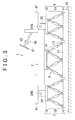
FIG. 3 is a side view illustrating the vehicle test apparatus inFIG. 1 ; -
FIG. 4 is a plan view illustrating the vehicle test apparatus inFIG. 1 ; -
FIG. 5A and FIG. 5B are schematic views for describing an example of the control of motion bases when a vehicle travelling condition during acceleration on a flat road is simulated,FIG. 5A illustrating a condition in which a vehicle is at a standstill on a flat road, andFIG. 5B illustrating a condition in which the vehicle is accelerating on a flat road; -
FIG. 6A and FIG. 6B are schematic views for describing an example of the control of the motion bases when a vehicle travelling condition during acceleration on a slope is simulated,FIG. 6A illustrating a condition in which the vehicle is at a standstill on a slope, andFIG. 6B illustrating a condition in which the vehicle is accelerating on a slope; -
FIG. 7A and FIG. 7B are schematic views for describing an example of the control of the motion bases when a vehicle travelling condition during turning is simulated,FIG. 7A illustrating a condition in which the vehicle is travelling straight ahead, andFIG. 7B illustrating a condition in which the vehicle is turning; -
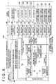
FIG. 8 is a block diagram schematically illustrating the electrical configuration of a vehicle test system; and -
FIG. 9A and FIG. 9B are views for describing the concept of impedance control when an external force in the x-direction is applied to a second motion base on the left front side. - Hereinafter, example embodiments of the invention will be described with reference to the accompanying drawings.
FIG. 1 is a perspective view schematically illustrating the appearance of a vehicle test apparatus included in a vehicle test system according to an embodiment of the invention.FIG. 2 is a front view illustrating the vehicle test apparatus inFIG. 1 .FIG. 3 is a side view illustrating the vehicle test apparatus inFIG. 1 .FIG. 4 is a plan view illustrating the vehicle test apparatus inFIG. 1 . InFIG. 4 , a test article installation vehicle body is not illustrated. - A vehicle test apparatus 1 includes: a test article
installation vehicle body 2 to which fouraxles first motion base 3 that supports the test articleinstallation vehicle body 2, and that causes the test articleinstallation vehicle body 2 to make motions of six degrees of freedom; and foursecond motion bases axles axles - In
FIG. 1 to FIG. 4 , a front end of the test articleinstallation vehicle body 2 is denoted by areference symbol 2f, and a rear end thereof is denoted by areference symbol 2r. No vehicle wheels are fitted to the fouraxles installation vehicle body 2. Output shafts of four electric motors (hereinafter, referred to as "external force applying motors") 31, 32, 33, 34 that apply torques to the fouraxles installation vehicle body 2 are connected to outer end portions of the fouraxles installation vehicle body 2. The externalforce applying motors corresponding axles - Test articles of automotive components of various kinds are installed on the test article
installation vehicle body 2. In the present embodiment, an electric power steering system (EPS) 40, and a rearwheel drive module 50 that drives theaxle 23S for the left rear wheel and theaxle 24S for the right rear wheel with the use of the electric motors are installed, as the test articles, on the test articleinstallation vehicle body 2. In the present embodiment, theEPS 40 is a column assist-type EPS. As is well known, theEPS 40 includes asteering wheel 81, asteering mechanism 82 that steers the front wheels in response to turning of thesteering wheel 81, and asteering assist mechanism 83 that assists a driver in performing a steering operation. Note that, in the present embodiment, thesteering mechanism 82 is not connected to the front wheels because no front wheels are provided. Thesteering wheel 81 and thesteering mechanism 82 are mechanically linked to each other via a steering shaft. - The
steering mechanism 82 includes a rack-and-pinion mechanism including a pinion provided at a lower end of the steering shaft, and a rack shaft having a rack that is meshed with the pinion. Thesteering assist mechanism 83 includes an electric motor 41 (refer toFIG. 8 , hereinafter referred to as "assistmotor 41") that generates a steering assist force, and a speed reduction mechanism (not illustrated) that transmits a torque output from theassist motor 41 to the steering shaft. - The
EPS 40 includes an ECU42 (refer toFIG. 8 , hereinafter referred to as "EPS ECU 42") that controls theassist motor 41, and a linear displacement sensor (not illustrated) that detects an axial displacement position of the rack shaft. The rearwheel drive module 50 includes an electric motor 51 (refer toFIG. 8 , hereinafter referred to as "rearwheel drive motor 51") that rotates theaxles wheel drive motor 51 to theaxles FIG. 8 , hereinafter referred to as "rear wheeldrive motor ECU 52") that controls the rearwheel drive motor 51, and a rotation angle sensor (not illustrated) that detects a rotation angle of at least one of theaxles - The motion bases 3, 4, 5, 6, 7 are secured to a
base plate 10 disposed on a floor. As is well known, each of themotion bases stationary base 11 secured to thebase plate 10, a movable base (moving base) 12 disposed above thestationary base 11, anactuator 13 that is disposed between and connected to thestationary base 11 and themovable base 12 and that causes themovable base 12 to make motions of six degrees of freedom (longitudinal, transverse, vertical, rolling, pitching and yawing motions), and a motion controller (not illustrated) that executes drive control of theactuator 13. Theactuator 13 is composed of six electric cylinders. - The test article
installation vehicle body 2 is secured to themovable base 12 of thefirst motion base 3, with a center portion of the test articleinstallation vehicle body 2 disposed on themovable base 12 of thefirst motion base 3. That is, the center portion of the bottom face of the test articleinstallation vehicle body 2 is attached to the top face of themovable base 12 of themotion base 3. The externalforce applying motor 31 is mounted on themovable base 12 of thesecond motion base 4 on the left front side. The externalforce applying motor 32 is mounted on themovable base 12 of thesecond motion base 5 on the right front side. The externalforce applying motor 33 is mounted on themovable base 12 of thesecond motion base 6 on the left rear side. The externalforce applying motor 34 is mounted on themovable base 12 of thesecond motion base 7 on the right rear side. - In the vehicle test apparatus 1, the test article
installation vehicle body 2 is supported by thefirst motion base 3. The externalforce applying motors second motion bases axles second motion bases force applying motors - Thus, in the vehicle test apparatus 1, various vehicle body postures can be created by executing drive control of the
actuator 13 of thefirst motion base 3. Various road surface conditions can be created by respectively executing drive control of theactuators 13 of thesecond motion bases actuators 13 of themotion bases - In the vehicle test apparatus 1, torques similar to the torques (external forces) externally applied to axles of an actual vehicle when the actual vehicle is travelling can be applied individually to the corresponding
axles installation vehicle body 2 by thefirst motion base 3 in the state where theaxles second motion bases installation vehicle body 2 without causing the test articleinstallation vehicle body 2 to move relative to the members that support theaxles - In the vehicle test apparatus 1, the test article
installation vehicle body 2 is allowed to make a yawing motion by thefirst motion base 3. Thus, it is possible to simulate a yawing motion. Hereinafter, more detailed description will be provided. In the following description, an X-axis denotes an axis that extends in the longitudinal direction of the vehicle body and passes through the center of gravity of the test articleinstallation vehicle body 2, a Y-axis denotes an axis that extends in the lateral direction of the vehicle body and passes through the center of gravity of the test articleinstallation vehicle body 2, and a Z-axis denotes an axis that extends in the up-down direction of the vehicle body and passes through the center of gravity of the test articleinstallation vehicle body 2. That is, the X-axis, Y-axis and Z-axis belong to a coordinate system (hereinafter, referred to as "vehicle body coordinate system) fixed to the test articleinstallation vehicle body 2. -
FIG. 5A and FIG. 5B are schematic views for describing an example of the control of themotion bases FIG. 5A illustrates a condition in which the vehicle is at a standstill on a flat road. In this case, the top faces of themovable bases 12 of themotion base base plate 10. Further, the heights of themovable bases 12 of themotion base base plate 10. - The vehicle travelling condition during acceleration on a flat road can be created as follows. As illustrated in
FIG. 5B , all thesecond motion bases FIG. 5A , and then theactuator 13 of thefirst motion base 3 is driven to rotate themovable base 12 of thefirst motion base 3 in a first direction (direction indicated by an arrow) around the Y-axis. The first direction around the Y-axis is such a direction that the front end of the test articleinstallation vehicle body 2 is lifted up. - That is, in the condition in which the external
force applying motors second motion bases movable base 12 of thefirst motion base 3 is rotated in the first direction around the Y-axis. Thus, a torque for rotating the test articleinstallation vehicle body 2 in the first direction around the Y-axis is directly applied to the test articleinstallation vehicle body 2. A force similar to an inertial force that is applied to the vehicle body of the actual vehicle during acceleration can be directly applied to the test articleinstallation vehicle body 2. Thus, it is possible to simulate the vehicle travelling condition during acceleration on a flat road, without causing the test articleinstallation vehicle body 2 to move relative to the members that support theaxles - In order to simulate a vehicle travelling condition during deceleration, the direction of a torque around the Y-axis, which is applied to the
movable base 12 of thefirst motion base 3, is set to the direction opposite to the first direction that is adopted when the vehicle travelling condition during acceleration is simulated (set to such a direction that the rear end of the test articleinstallation vehicle body 2 is lifted up).FIG. 6A and FIG. 6B are schematic views for describing an example of the control of themotion bases -
FIG. 6A illustrates a condition in which the vehicle is at a standstill on a slope. In this case, the top faces of themovable bases 12 of themotion bases movable bases 12 of themotion bases - This standstill condition can be created from the standstill condition on a flat road in the following manner. The
movable base 12 of thefirst motion base 3 is rotated by a prescribed degree in the first direction around the Y-axis in accordance with a slope angle of the slope. At the same time, themovable bases 12 of thesecond motion bases installation vehicle body 2 is lifted up. In this case, themovable bases 12 of the twosecond motion bases movable bases 12 of the twosecond motion bases - The vehicle travelling condition during acceleration on a slope can be created from the standstill condition illustrated in
FIG. 6A in the following manner. As illustrated inFIG. 6B , themovable bases 12 of all thesecond motion bases FIG. 6A , and theactuator 13 of thefirst motion base 3 is driven to rotate themovable base 12 of thefirst motion base 3 in the first direction (indicated by an arrow) around the Y-axis. - In the condition in which the external
force applying motors movable base 12 of thefirst motion base 3 is rotated in the first direction around the Y-axis. Thus, a torque for rotating the test articleinstallation vehicle body 2 in the first direction around the Y-axis is directly applied to the test articleinstallation vehicle body 2. That is, a force similar to an inertial force that is applied to the vehicle body of the actual vehicle during acceleration on a slope (uphill slope in this case), can be directly applied to the test articleinstallation vehicle body 2. Thus, it is possible to simulate the vehicle travelling condition during acceleration on a slope without causing the test articleinstallation vehicle body 2 to move relative to the members that support theaxles - Note that, in order to simulate a vehicle travelling condition during deceleration on a slope, the direction of a torque around the Y-axis, which is applied to the
movable base 12 of thefirst motion base 3, is set to the direction opposite to the first direction that is adopted when the vehicle travelling condition during acceleration on a slope is simulated (set to such a direction that the rear end of the test articleinstallation vehicle body 2 is lifted up).FIG. 7A and FIG. 7B are schematic views for describing an example of the control of themotion bases -
FIG. 7A illustrates a condition in which the vehicle is travelling straight ahead. The case where the vehicle turns to the left, as illustrated inFIG. 7B , from the condition in which the vehicle is travelling straight ahead, will be described. As illustrated inFIG. 7B , in order to turn the test articleinstallation vehicle body 2 to the left, themovable base 12 of thefirst motion base 3 is rotated counterclockwise around the Z-axis as viewed in a planar view. Themovable bases 12 of all the second motion bases, 4, 5, 6, 7 are rotated counterclockwise around the Z-axis as viewed in a plan view, and are moved in the XY plane defined by the X-axis and Y-axis of the vehicle body coordinate system in order to move the externalforce applying motors installation vehicle body 2. Thus, themovable bases 12 of the second motion bases, 4, 5, 6, 7 are moved from positions indicated by two-dot chain lines to positions indicated by solid lines inFIG. 7B . Thus, the travelling condition during turning can be simulated. In this case, it is possible to evaluate axial loads applied to theaxles - Hereinafter, a
vehicle test system 100 including the vehicle test apparatus 1 will be described.FIG. 8 is a block diagram schematically illustrating the electrical configuration of thevehicle test system 100. Thevehicle test system 100 includes a drivingsimulator 60, the vehicle test apparatus 1 and anactuator controller 70. The drivingsimulator 60 virtually simulates a vehicle operation, and is manipulated by an operator. In the vehicle test apparatus 1, theEPS 40, the rearwheel drive module 50 andmotor controllers force applying motors actuator controller 70 is a computer, and controls themotion bases motor controllers - As described above, the
EPS 40 includes theassist motor 41, theEPS ECU 42 that controls theassist motor 41, and the linear displacement sensor (not illustrated) that detects an axial displacement position of the rack shaft. As described above, the rearwheel drive module 50 includes the rearwheel drive motor 51, the rear wheeldrive motor ECU 52 that controls the rearwheel drive motor 51, and the rotation angle sensor (not illustrated) that detects a rotation angle of at least one of therear wheel axles - The
second motion bases axis force sensors second motion bases installation vehicle body 2 via theaxles 21S to 24S and the externalforce applying motors - For example, steering angle information (steering wheel angle information), accelerator operation degree information, and brake depression force information according to an operation of the driving
simulator 60 are output from the drivingsimulator 60. The steering angle information output from the drivingsimulator 60 is transmitted to theEPS ECU 42 mounted on the vehicle test apparatus 1. The accelerator operation degree information output from the drivingsimulator 60 is transmitted to the rear wheeldrive motor ECU 52 mounted on the vehicle test apparatus 1. The brake depression force information output from the drivingsimulator 60 is transmitted to theactuator controller 70. Instead of the brake depression force information, brake depression degree information may be used. - The
EPS ECU 42 determines a steering torque on the basis of the steering angle information transmitted from the drivingsimulator 60, and executes drive control of theassist motor 41 on the basis of the thus determined steering torque. TheEPS ECU 42 measures an axial displacement amount of the rack shaft included in the EPS 40 (hereinafter, referred to as "rack shaft displacement amount"), and an axial displacement velocity of the rack shaft (hereinafter, referred to as "rack shaft displacement velocity"), on the basis of an output signal from the linear displacement sensor, and transmits the thus measured values to theactuator controller 70. - The rear wheel
drive motor ECU 52 determines a torque command value for the rearwheel drive motor 51 on the basis of the accelerator operation degree information transmitted from the drivingsimulator 60, and executes drive control of the rearwheel drive motor 51 on the basis of the thus determined torque command value. Further, the rear wheeldrive motor ECU 52 measures rotational speeds of therear wheel axles actuator controller 70. - The
actuator controller 70 includes avehicle model 71, a motion base first target value generator 72 (hereinafter, referred to as "MB firsttarget value generator 72"), a motion base second target value generator 73 (hereinafter, referred to as "MB secondtarget value generator 73"), a displacementdegree computing unit 74, and a motortarget value generator 75. Thevehicle model 71 receives the brake depression force information output from the drivingsimulator 60, the rack shaft displacement amount and the rack shaft displacement velocity that are transmitted from theEPS ECU 42, and the axle rotational speed transmitted from the rear wheeldrive motor ECU 52. Thevehicle model 71 creates a position and a posture of the vehicle body, positions and postures of the wheels, and external forces applied to the axles in accordance with the operating condition simulated by the drivingsimulator 60. - The motor
target value generator 75 generates target values (torque target values) of motor torques that should be generated by the externalforce applying motors vehicle model 71 and applied to theaxles force applying motors target value generator 75, are provided to thecorresponding motor controllers motor controllers force applying motors target value generator 75. Thus, the externalforce applying motors - The MB first
target value generator 72 generates target values (position and posture target values) of positions and postures that are to be taken by themotion bases vehicle model 71. The position and posture target values for thefirst motion base 3, which are generated by the MB firsttarget value generator 72, are provided to a motion controller 3C for thefirst motion base 3. The motion controller 3C for thefirst motion base 3 controls the correspondingactuator 13 on the basis of the position and posture target values provided by the MB firsttarget value generator 72. Thus, the position and posture of themovable base 12 of thefirst motion base 3 are controlled so as to coincide with the position and posture corresponding to the position and posture target values. - On the assumption that each of the
second motion bases degree computing unit 74 computes the degrees of six-degree-of-freedom displacements of thesecond motion bases axis force sensors degree computing unit 74 will be described later in detail. - The position and posture target values for the
second motion bases target value generator 72 are provided to the MB secondtarget value generator 73. The MB secondtarget value generator 73 generates final position and posture target values for thesecond motion bases second motion bases second motion bases degree computing unit 74. Specifically, the MB secondtarget value generator 73 generates the final position and posture target values for thesecond motion bases second motion bases second motion bases - The final position and posture target values for the
second motion bases target value generator 73 are provided tomotion controllers second motion bases motion controllers second motion bases actuators 13 based on the final position and posture target values provided by the MB secondtarget value generator 73. Thus, the positions and postures of themovable bases 12 of thesecond motion bases - Hereinafter, the operation of the displacement
degree computing unit 74 will be described. The six-axis force sensors degree computing unit 74 and the MB secondtarget value generator 73 constitute an impedance controller that executes impedance control. The impedance control is a control for causing a behavior of a target mass when an external force is applied to the target mass, to coincide with a behavior of a virtual mechanical impedance model including a virtual spring, a virtual mass and a virtual damper. Specifically, a force-torque sensor (six-axis force sensor) provided on the target mass detects external forces of respective six degrees of freedom (external forces and external torques), and inputs the detected values into the virtual mechanical impedance model. It is possible to obtain translational and rotational behaviors of the target mass from the virtual mechanical impedance model and the input values. If the translational and the rotational behaviors are provided as position and posture target values for the actuators, it is possible to realize the above-described control. -
FIG. 9A and FIG. 9B are views for describing the concept of impedance control when an external force in the x-direction is applied to the second motion base on the left front side. The x-axis, y-axis and z-axis inFIG. 9A and FIG. 9B belong to an xyz coordinate system fixed to the second motion base on the left front side. As illustrated inFIG. 9A , a virtualmechanical impedance 200 is disposed between themovable base 12 of thesecond motion base 4 on the front left side and a virtual vertical wall. The virtualmechanical impedance 200 is formed of avirtual spring 201 and avirtual damper 202. When an external force in the x-direction is applied to themovable base 12, thevirtual spring 201 is deformed in the x-direction based on the external force, and thevirtual damper 202 attenuates the external force. Themovable base 12 of thesecond motion base 4 is provided with the six-axis force sensor 104 that detects external forces (external forces and external torques) of respective six degrees of freedom applied from the test articleinstallation vehicle body 2 via theaxles 21S. Note that, actually, the six-axis force sensor 104 is disposed at such a position that attachment of the externalforce applying motor 31 is not hindered. - As illustrated in
FIG. 9B , when an external force Fx in the x-axis direction is applied to themovable base 12 of thesecond motion base 4, the external force Fx is attenuated by thevirtual damper 202 and thevirtual spring 201 is deformed. As a result, themovable base 12 is displaced in the x-direction by a displacement degree Δx. The displacement degree Δx is computed by the displacementdegree computing unit 74, and is reflected in the position and posture target values for thesecond motion base 4. - The displacement
degree computing unit 74 computes the six-degree-of-freedom displacements corresponding to the external forces of respective six degrees of freedom with the use of the virtual mechanical impedance model. The virtual mechanical impedance model is defined Equations (1) to (4) indicated below. In Equations (1) to (4), a dash on the upper right side of a symbol denotes expression in a coordinate system fixed to a target mass, which is called as a body coordinate system, and a tilde denotes a skew-symmetric matrix.


MD: virtual mass of virtual mechanical impedance model
VD: translational velocity of target mass
FS: external force detected by six-axis force sensor
FVS: force produced by virtual spring
FVD: force produced by virtual damper
XD: displacement of target mass
JD: virtual inertia moment (inertia tensor) of virtual mechanical impedance model
QD: angular velocity of target mass
TS: external torque detected by six-axis force sensor
TVS: torque produced by virtual spring
TVD: torque produced by virtual damper
Θ : Eulerian angle of target mass - Equation (1) is a dynamic equation (a kinetic equation) of translational motions (translational motions in the x-direction, y-direction and z-direction). Equation (2) is a kinetic equation that defines a relationship between a translational velocity and a displacement. Equation (3) is a dynamic equation (a kinetic equation) of a rotational motion. Equation (4) is a kinetic equation that defines a relationship between an angular velocity and a posture. A posture is expressed by Eulerian angles (a roll angle α, a pitch angle β and a yaw angle y).
- Fvs, FVD, TVS, TVD are defined by Equations (5), (6), (7), (8), respectively.


KTVS: virtual translational stiffness of virtual mechanical impedance model (expressed in the body coordinate system)
CTVD: virtual translational viscosity of virtual mechanical impedance model (expressed in the body coordinate system)
KRVS: torsional stiffness of virtual mechanical impedance model (expressed in the body coordinate system)
CRVD: torsional viscosity of virtual mechanical impedance model (expressed in the body coordinate system) - MD, JD, KTVS, KTVD, KRVS, KRVD are parameters of the virtual mechanical impedance model, and a user can set any values as the parameters. As the stiffness and viscosity, values used in place of the spring and the damper should be selected. As the mass, a value obtained by adding a load mass of a test target to a mass of the movable base portion should be selected. The displacement
degree computing unit 74 computes six-degree-of-freedom displacements of thesecond motion bases axis force sensors 104 to 107, and Equations (1) to (8). - In the vehicle test apparatus 1, various vehicle travelling conditions (vehicle behaviors) are reproduced by moving the test article
installation vehicle body 2 and theaxles motion bases motion bases motion bases installation vehicle body 2 and the externalforce applying motors motion bases - In the present embodiment, the final position and posture target values for the
second motion bases second motion bases target value generator 72 and the six-degree-of-freedom displacements of thesecond motion bases degree computing unit 74. The positions and postures of thesecond motion bases second motion bases - Thus, each of the
second motion bases motion bases second motion bases installation vehicle body 2. Further, controllers (for example, theactuator controller 70, and themotion controllers motion bases - While one example embodiment of the invention has been described above, the invention may be implemented in various other embodiments. For example, in the aforementioned embodiment, the impedance control is adopted only for the position and posture control of the
second motion bases first motion base 3.
Claims (4)
- A vehicle test system comprising:a test article installation vehicle body to which four axles corresponding to four wheels that are a left front wheel, a right front wheel, a left rear wheel and a right rear wheel are attached, and on which a test article is installed;a first motion base that supports the test article installation vehicle body, and that allows the test article installation vehicle body to make motions of six degrees of freedom;four electric motors that are connected to outer end portions of the respective axles to apply torques to the respective axles;four second motion bases that support the respective axles via the corresponding electric motors, and that allow the respective axles to make motions of six degrees of freedom;four external force detectors that individually detect external forces applied to the respective second motion bases from the test article installation vehicle body via the respective axles;a first target value generator that generates target values of a position and a posture to be taken by each of the motion bases, for each of the motion bases;a displacement degree computing unit that computes a degree of displacement of each of the second motion bases, which corresponds to the external force detected by a corresponding one of the external force detectors, on an assumption that each of the second motion bases has a virtual mechanical impedance for producing flexibility against the external force;a second target value generator that generates final position and posture target values for each of the second motion bases based on the position and posture target values for each of the second motion bases generated by the first target value generator and the degree of displacement of each of the second motion bases computed by the displacement degree computing unit; anda controller that controls the first motion base using the position and posture target values for the first motion base generated by the first target value generator, and controls the second motion bases using the final position and posture target values for the second motion bases generated by the second target value generator.
- The vehicle test system according to claim 1, wherein:each of the external force detectors is configured to detect external forces of respective six degrees of freedom applied to a corresponding one of the second motion bases from the test article installation vehicle body;the virtual mechanical impedance of each of the second motion bases is formed of virtual mechanical impedances of respective six degrees of freedom that correspond to the external forces of respective six degrees of freedom; andthe displacement degree computing unit is configured to compute degrees of six-degree-of-freedom displacements of the second motion bases, which correspond to the external forces of respective six degrees of freedom detected by the external force detectors.
- The vehicle test system according to claim 1 or 2, wherein the virtual mechanical impedances of respective six degrees of freedom include a virtual spring and a virtual damper.
- The vehicle test system according to any one of claims 1 to 3, wherein
each of the motion bases includes
a stationary base,
a movable base disposed above the stationary base, and
an actuator that is disposed between and connected to the stationary base and the movable base, and that allows the movable base to make motions of six degrees of freedom;
the test article installation vehicle body is disposed on the movable base of the first motion base and fixed to the movable base of the first motion base; and
the electric motors are connected to the corresponding movable bases of the second motion bases.
Applications Claiming Priority (1)
| Application Number | Priority Date | Filing Date | Title |
|---|---|---|---|
| JP2013094083A JP6057131B2 (en) | 2013-04-26 | 2013-04-26 | Vehicle test system |
Publications (3)
| Publication Number | Publication Date |
|---|---|
| EP2796850A2 true EP2796850A2 (en) | 2014-10-29 |
| EP2796850A3 EP2796850A3 (en) | 2014-12-03 |
| EP2796850B1 EP2796850B1 (en) | 2017-08-23 |
Family
ID=50513146
Family Applications (1)
| Application Number | Title | Priority Date | Filing Date |
|---|---|---|---|
| EP14165588.6A Not-in-force EP2796850B1 (en) | 2013-04-26 | 2014-04-23 | Vehicle test system |
Country Status (4)
| Country | Link |
|---|---|
| US (1) | US9442044B2 (en) |
| EP (1) | EP2796850B1 (en) |
| JP (1) | JP6057131B2 (en) |
| CN (1) | CN104122097B (en) |
Families Citing this family (17)
| Publication number | Priority date | Publication date | Assignee | Title |
|---|---|---|---|---|
| JP6057131B2 (en) | 2013-04-26 | 2017-01-11 | 株式会社ジェイテクト | Vehicle test system |
| JP6202303B2 (en) * | 2013-04-26 | 2017-09-27 | 株式会社ジェイテクト | VEHICLE TEST DEVICE AND VEHICLE TEST SYSTEM |
| DE102015007672A1 (en) * | 2015-06-16 | 2016-12-22 | GM Global Technology Operations LLC (n. d. Ges. d. Staates Delaware) | Test arrangement for simulated testing of a vehicle on at least one test stand, test bench with the test arrangement and method for simulated testing of a vehicle on at least one test stand with the test arrangement |
| US10350450B2 (en) * | 2016-01-13 | 2019-07-16 | John Stelmach | Lateral tilting treadmill systems |
| CN106124228A (en) * | 2016-09-07 | 2016-11-16 | 长春孔辉汽车科技股份有限公司 | K & C attribute testing platform six degree of freedom formula measures arm assembly |
| US9927312B1 (en) * | 2017-03-03 | 2018-03-27 | Bertec Corporation | Motion base for displacing a force measurement assembly |
| CN106940258B (en) * | 2017-04-18 | 2019-09-10 | 上海测迅汽车科技有限公司 | Automatic driving vehicle comprehensive performance testing system |
| US10928832B2 (en) * | 2017-09-29 | 2021-02-23 | Huawei Technologies Co., Ltd. | Impedance-based motion control for autonomous vehicles |
| EP3792611B1 (en) * | 2018-05-10 | 2024-09-18 | Toyo Denki Seizo Kabushiki Kaisha | Chassis dynamometer apparatus |
| USD900216S1 (en) * | 2019-03-30 | 2020-10-27 | Robert Harrison | Rollover simulator |
| USD900217S1 (en) * | 2019-10-07 | 2020-10-27 | Robert Harrison | Rollover simulator |
| US11604118B2 (en) * | 2020-12-15 | 2023-03-14 | GM Global Technology Operations LLC | Strut module test machine |
| CN113865887A (en) * | 2021-10-18 | 2021-12-31 | 河南科技大学 | A vehicle vibration test bench based on a six-degree-of-freedom parallel mechanism |
| CN114813171B (en) * | 2022-06-27 | 2022-09-09 | 山东亚华机械制造有限公司 | Vehicle body rigidity simulation experiment equipment for suspension test |
| CN116300667B (en) * | 2023-05-25 | 2024-02-23 | 中国科学院长春光学精密机械与物理研究所 | Modular combination adjustment platform and control method of the adjustment platform |
| US20250005971A1 (en) * | 2023-06-30 | 2025-01-02 | Mitsubishi Electric Automotive America, Inc. | Development environment facilitating remote testing of automotive embedded device |
| KR102765789B1 (en) * | 2024-09-09 | 2025-02-11 | 서울대학교산학협력단 | 6-Degree of Freedom Actuating System for Real-time Hybrid Simulation |
Citations (4)
| Publication number | Priority date | Publication date | Assignee | Title |
|---|---|---|---|---|
| JP2000512610A (en) | 1996-02-14 | 2000-09-26 | ディーエスエム エヌ.ブイ. | Mortar manufacturing method |
| JP2006138827A (en) | 2004-10-14 | 2006-06-01 | Kobe Steel Ltd | Tire HIL simulator |
| JP2008175778A (en) | 2007-01-22 | 2008-07-31 | Mitsubishi Heavy Ind Ltd | Vehicle testing device and roll-over testing method |
| JP2009536736A (en) | 2006-05-08 | 2009-10-15 | エムティーエス システムズ コーポレイション | Vehicle testing and simulation using embedded simulation models and physical components |
Family Cites Families (21)
| Publication number | Priority date | Publication date | Assignee | Title |
|---|---|---|---|---|
| US4263809A (en) * | 1979-07-02 | 1981-04-28 | Mts Systems Corporation | Tetraxial vehicle test fixture |
| DE3723476A1 (en) * | 1987-07-16 | 1989-01-26 | Schenck Ag Carl | VIBRATION TEST FOR VEHICLES, IN PARTICULAR PERSONAL CARS |
| US5111685A (en) * | 1989-12-20 | 1992-05-12 | Mts Systems Corporation | Roadway simulator restraint |
| US5942673A (en) * | 1996-05-24 | 1999-08-24 | Hitachi, Ltd. | Vehicle testing system and testing method |
| CZ20013491A3 (en) * | 1999-03-31 | 2002-05-15 | Siemens Aktiengesellschaft | Dynamic testing equipment for a vehicle, test room and production line fitted with such dynamic testing equipment as well as use thereof for verification of safety system of transversal stability in a vehicle |
| JP3766038B2 (en) * | 2002-04-10 | 2006-04-12 | 株式会社鷺宮製作所 | Vehicle spindle load device |
| US7058488B2 (en) * | 2002-05-03 | 2006-06-06 | Burke E. Porter Machinery Company | Vehicle testing apparatus for measuring a propensity of a vehicle to roll over |
| CN1771433A (en) * | 2003-03-28 | 2006-05-10 | Mts系统公司 | Vehicle crash simulator with dynamic motion simulation |
| JP2005091144A (en) * | 2003-09-17 | 2005-04-07 | Mitsubishi Heavy Ind Ltd | Bench test method and bench test system |
| CN2757112Y (en) * | 2004-06-29 | 2006-02-08 | 财团法人车辆研究测试中心 | Locomotive road condition simulation test organization |
| JP4523818B2 (en) * | 2004-09-09 | 2010-08-11 | 株式会社ブリヂストン | Wheel attitude angle measuring device and wheel attitude angle measuring method |
| US7174776B2 (en) * | 2004-09-22 | 2007-02-13 | Daimlerchrysler Corporation | Methodology for vehicle box component durability test development |
| DE102005022096A1 (en) * | 2005-05-12 | 2006-11-16 | Fraunhofer-Gesellschaft zur Förderung der angewandten Forschung e.V. | Device and method for vibroacoustic examination of a motor vehicle |
| JP4005618B2 (en) * | 2006-04-14 | 2007-11-07 | 株式会社神戸製鋼所 | Tire braking characteristics testing device |
| JP2009220184A (en) | 2008-03-13 | 2009-10-01 | Nachi Fujikoshi Corp | Output torque limiting circuit of industrial robot |
| CN101776526A (en) * | 2010-01-26 | 2010-07-14 | 郭孔辉 | Kinematics and total working condition elastic tester of suspension bracket |
| CN104024819B (en) * | 2011-10-20 | 2017-05-03 | Mts系统公司 | Test System For Measuring And Evaluating Dynamic Body Forces |
| DE102011120171A1 (en) | 2011-12-06 | 2012-06-14 | Daimler Ag | Vehicle test rig for gear examination, has wheel carrier attachment elements connected to wheel carriers, and vehicle receiving seat having additional degree of freedom of movement such that corresponding attachment element is movable |
| DE102012101613B4 (en) * | 2011-12-22 | 2021-11-04 | Dr. Ing. H.C. F. Porsche Aktiengesellschaft | Test bench for motor vehicles |
| JP6202303B2 (en) * | 2013-04-26 | 2017-09-27 | 株式会社ジェイテクト | VEHICLE TEST DEVICE AND VEHICLE TEST SYSTEM |
| JP6057131B2 (en) | 2013-04-26 | 2017-01-11 | 株式会社ジェイテクト | Vehicle test system |
-
2013
- 2013-04-26 JP JP2013094083A patent/JP6057131B2/en not_active Expired - Fee Related
-
2014
- 2014-04-18 US US14/256,636 patent/US9442044B2/en not_active Expired - Fee Related
- 2014-04-23 EP EP14165588.6A patent/EP2796850B1/en not_active Not-in-force
- 2014-04-24 CN CN201410168715.8A patent/CN104122097B/en not_active Expired - Fee Related
Patent Citations (4)
| Publication number | Priority date | Publication date | Assignee | Title |
|---|---|---|---|---|
| JP2000512610A (en) | 1996-02-14 | 2000-09-26 | ディーエスエム エヌ.ブイ. | Mortar manufacturing method |
| JP2006138827A (en) | 2004-10-14 | 2006-06-01 | Kobe Steel Ltd | Tire HIL simulator |
| JP2009536736A (en) | 2006-05-08 | 2009-10-15 | エムティーエス システムズ コーポレイション | Vehicle testing and simulation using embedded simulation models and physical components |
| JP2008175778A (en) | 2007-01-22 | 2008-07-31 | Mitsubishi Heavy Ind Ltd | Vehicle testing device and roll-over testing method |
Also Published As
| Publication number | Publication date |
|---|---|
| JP6057131B2 (en) | 2017-01-11 |
| EP2796850A3 (en) | 2014-12-03 |
| CN104122097A (en) | 2014-10-29 |
| US20140318229A1 (en) | 2014-10-30 |
| US9442044B2 (en) | 2016-09-13 |
| EP2796850B1 (en) | 2017-08-23 |
| JP2014215225A (en) | 2014-11-17 |
| CN104122097B (en) | 2018-06-01 |
Similar Documents
| Publication | Publication Date | Title |
|---|---|---|
| US9442044B2 (en) | Vehicle test system | |
| EP2796849B1 (en) | Vehicle test apparatus and vehicle test system | |
| KR100967510B1 (en) | Braking Characteristics Testing Device of Tire | |
| US7421890B2 (en) | Tire HIL simulator | |
| JP2014215240A (en) | Vehicle testing device | |
| JP2014215242A (en) | Test device for vehicle | |
| JP6164465B2 (en) | Motion control method and vehicle test system for driving simulator | |
| JP2015040762A (en) | Simulation device for evaluating vehicle maneuverability | |
| JP2016212236A (en) | Simulator | |
| CN114290318A (en) | A multi-DOF motion platform suitable for large-angle compound attitude motion and its motion control inverse solution method | |
| JP2014215241A (en) | Vehicle test system | |
| JP6801525B2 (en) | Test equipment | |
| Wang et al. | Evaluation of alternative steering devices with adjustable haptic feedback for semi-autonomous and autonomous vehicles | |
| JP7326937B2 (en) | tire test system | |
| JPS6310775B2 (en) | ||
| JP2014215224A (en) | Testing apparatus for vehicle | |
| JP2014215226A (en) | Testing apparatus for vehicle | |
| JP2014215227A (en) | Testing apparatus for vehicle | |
| JP2014215228A (en) | Test device for vehicle | |
| Witaya et al. | Scaled vehicle for Interactive dynamic Simulation (SIS) | |
| JP2020122745A (en) | Tire testing device and tire drive control device | |
| JP6380798B2 (en) | Vehicle behavior reproduction system | |
| JP2023172537A (en) | Vehicle test device and vehicle test method | |
| JP2000132084A (en) | Driving simulator | |
| JP2000132083A (en) | Simulation system for vehicle |
Legal Events
| Date | Code | Title | Description |
|---|---|---|---|
| PUAI | Public reference made under article 153(3) epc to a published international application that has entered the european phase |
Free format text: ORIGINAL CODE: 0009012 |
|
| 17P | Request for examination filed |
Effective date: 20140423 |
|
| AK | Designated contracting states |
Kind code of ref document: A2 Designated state(s): AL AT BE BG CH CY CZ DE DK EE ES FI FR GB GR HR HU IE IS IT LI LT LU LV MC MK MT NL NO PL PT RO RS SE SI SK SM TR |
|
| AX | Request for extension of the european patent |
Extension state: BA ME |
|
| PUAL | Search report despatched |
Free format text: ORIGINAL CODE: 0009013 |
|
| RIC1 | Information provided on ipc code assigned before grant |
Ipc: G01M 17/06 20060101ALI20141020BHEP Ipc: G01M 17/04 20060101ALI20141020BHEP Ipc: G01M 17/007 20060101AFI20141020BHEP |
|
| AK | Designated contracting states |
Kind code of ref document: A3 Designated state(s): AL AT BE BG CH CY CZ DE DK EE ES FI FR GB GR HR HU IE IS IT LI LT LU LV MC MK MT NL NO PL PT RO RS SE SI SK SM TR |
|
| AX | Request for extension of the european patent |
Extension state: BA ME |
|
| RIC1 | Information provided on ipc code assigned before grant |
Ipc: G01M 17/04 20060101ALI20141024BHEP Ipc: G01M 17/06 20060101ALI20141024BHEP Ipc: G01M 17/007 20060101AFI20141024BHEP |
|
| R17P | Request for examination filed (corrected) |
Effective date: 20150529 |
|
| RBV | Designated contracting states (corrected) |
Designated state(s): AL AT BE BG CH CY CZ DE DK EE ES FI FR GB GR HR HU IE IS IT LI LT LU LV MC MK MT NL NO PL PT RO RS SE SI SK SM TR |
|
| GRAP | Despatch of communication of intention to grant a patent |
Free format text: ORIGINAL CODE: EPIDOSNIGR1 |
|
| GRAJ | Information related to disapproval of communication of intention to grant by the applicant or resumption of examination proceedings by the epo deleted |
Free format text: ORIGINAL CODE: EPIDOSDIGR1 |
|
| GRAJ | Information related to disapproval of communication of intention to grant by the applicant or resumption of examination proceedings by the epo deleted |
Free format text: ORIGINAL CODE: EPIDOSDIGR1 |
|
| GRAP | Despatch of communication of intention to grant a patent |
Free format text: ORIGINAL CODE: EPIDOSNIGR1 |
|
| INTG | Intention to grant announced |
Effective date: 20170314 |
|
| GRAS | Grant fee paid |
Free format text: ORIGINAL CODE: EPIDOSNIGR3 |
|
| GRAA | (expected) grant |
Free format text: ORIGINAL CODE: 0009210 |
|
| AK | Designated contracting states |
Kind code of ref document: B1 Designated state(s): AL AT BE BG CH CY CZ DE DK EE ES FI FR GB GR HR HU IE IS IT LI LT LU LV MC MK MT NL NO PL PT RO RS SE SI SK SM TR |
|
| REG | Reference to a national code |
Ref country code: GB Ref legal event code: FG4D |
|
| REG | Reference to a national code |
Ref country code: CH Ref legal event code: EP |
|
| REG | Reference to a national code |
Ref country code: AT Ref legal event code: REF Ref document number: 921859 Country of ref document: AT Kind code of ref document: T Effective date: 20170915 |
|
| REG | Reference to a national code |
Ref country code: IE Ref legal event code: FG4D |
|
| REG | Reference to a national code |
Ref country code: DE Ref legal event code: R096 Ref document number: 602014013379 Country of ref document: DE |
|
| REG | Reference to a national code |
Ref country code: NL Ref legal event code: MP Effective date: 20170823 |
|
| REG | Reference to a national code |
Ref country code: LT Ref legal event code: MG4D |
|
| REG | Reference to a national code |
Ref country code: AT Ref legal event code: MK05 Ref document number: 921859 Country of ref document: AT Kind code of ref document: T Effective date: 20170823 |
|
| PG25 | Lapsed in a contracting state [announced via postgrant information from national office to epo] |
Ref country code: NL Free format text: LAPSE BECAUSE OF FAILURE TO SUBMIT A TRANSLATION OF THE DESCRIPTION OR TO PAY THE FEE WITHIN THE PRESCRIBED TIME-LIMIT Effective date: 20170823 Ref country code: SE Free format text: LAPSE BECAUSE OF FAILURE TO SUBMIT A TRANSLATION OF THE DESCRIPTION OR TO PAY THE FEE WITHIN THE PRESCRIBED TIME-LIMIT Effective date: 20170823 Ref country code: AT Free format text: LAPSE BECAUSE OF FAILURE TO SUBMIT A TRANSLATION OF THE DESCRIPTION OR TO PAY THE FEE WITHIN THE PRESCRIBED TIME-LIMIT Effective date: 20170823 Ref country code: HR Free format text: LAPSE BECAUSE OF FAILURE TO SUBMIT A TRANSLATION OF THE DESCRIPTION OR TO PAY THE FEE WITHIN THE PRESCRIBED TIME-LIMIT Effective date: 20170823 Ref country code: FI Free format text: LAPSE BECAUSE OF FAILURE TO SUBMIT A TRANSLATION OF THE DESCRIPTION OR TO PAY THE FEE WITHIN THE PRESCRIBED TIME-LIMIT Effective date: 20170823 Ref country code: LT Free format text: LAPSE BECAUSE OF FAILURE TO SUBMIT A TRANSLATION OF THE DESCRIPTION OR TO PAY THE FEE WITHIN THE PRESCRIBED TIME-LIMIT Effective date: 20170823 Ref country code: NO Free format text: LAPSE BECAUSE OF FAILURE TO SUBMIT A TRANSLATION OF THE DESCRIPTION OR TO PAY THE FEE WITHIN THE PRESCRIBED TIME-LIMIT Effective date: 20171123 |
|
| PG25 | Lapsed in a contracting state [announced via postgrant information from national office to epo] |
Ref country code: RS Free format text: LAPSE BECAUSE OF FAILURE TO SUBMIT A TRANSLATION OF THE DESCRIPTION OR TO PAY THE FEE WITHIN THE PRESCRIBED TIME-LIMIT Effective date: 20170823 Ref country code: BG Free format text: LAPSE BECAUSE OF FAILURE TO SUBMIT A TRANSLATION OF THE DESCRIPTION OR TO PAY THE FEE WITHIN THE PRESCRIBED TIME-LIMIT Effective date: 20171123 Ref country code: LV Free format text: LAPSE BECAUSE OF FAILURE TO SUBMIT A TRANSLATION OF THE DESCRIPTION OR TO PAY THE FEE WITHIN THE PRESCRIBED TIME-LIMIT Effective date: 20170823 Ref country code: PL Free format text: LAPSE BECAUSE OF FAILURE TO SUBMIT A TRANSLATION OF THE DESCRIPTION OR TO PAY THE FEE WITHIN THE PRESCRIBED TIME-LIMIT Effective date: 20170823 Ref country code: ES Free format text: LAPSE BECAUSE OF FAILURE TO SUBMIT A TRANSLATION OF THE DESCRIPTION OR TO PAY THE FEE WITHIN THE PRESCRIBED TIME-LIMIT Effective date: 20170823 Ref country code: GR Free format text: LAPSE BECAUSE OF FAILURE TO SUBMIT A TRANSLATION OF THE DESCRIPTION OR TO PAY THE FEE WITHIN THE PRESCRIBED TIME-LIMIT Effective date: 20171124 Ref country code: IS Free format text: LAPSE BECAUSE OF FAILURE TO SUBMIT A TRANSLATION OF THE DESCRIPTION OR TO PAY THE FEE WITHIN THE PRESCRIBED TIME-LIMIT Effective date: 20171223 |
|
| REG | Reference to a national code |
Ref country code: FR Ref legal event code: PLFP Year of fee payment: 5 |
|
| PG25 | Lapsed in a contracting state [announced via postgrant information from national office to epo] |
Ref country code: DK Free format text: LAPSE BECAUSE OF FAILURE TO SUBMIT A TRANSLATION OF THE DESCRIPTION OR TO PAY THE FEE WITHIN THE PRESCRIBED TIME-LIMIT Effective date: 20170823 Ref country code: CZ Free format text: LAPSE BECAUSE OF FAILURE TO SUBMIT A TRANSLATION OF THE DESCRIPTION OR TO PAY THE FEE WITHIN THE PRESCRIBED TIME-LIMIT Effective date: 20170823 Ref country code: RO Free format text: LAPSE BECAUSE OF FAILURE TO SUBMIT A TRANSLATION OF THE DESCRIPTION OR TO PAY THE FEE WITHIN THE PRESCRIBED TIME-LIMIT Effective date: 20170823 |
|
| REG | Reference to a national code |
Ref country code: DE Ref legal event code: R097 Ref document number: 602014013379 Country of ref document: DE |
|
| PG25 | Lapsed in a contracting state [announced via postgrant information from national office to epo] |
Ref country code: SM Free format text: LAPSE BECAUSE OF FAILURE TO SUBMIT A TRANSLATION OF THE DESCRIPTION OR TO PAY THE FEE WITHIN THE PRESCRIBED TIME-LIMIT Effective date: 20170823 Ref country code: EE Free format text: LAPSE BECAUSE OF FAILURE TO SUBMIT A TRANSLATION OF THE DESCRIPTION OR TO PAY THE FEE WITHIN THE PRESCRIBED TIME-LIMIT Effective date: 20170823 Ref country code: SK Free format text: LAPSE BECAUSE OF FAILURE TO SUBMIT A TRANSLATION OF THE DESCRIPTION OR TO PAY THE FEE WITHIN THE PRESCRIBED TIME-LIMIT Effective date: 20170823 Ref country code: IT Free format text: LAPSE BECAUSE OF FAILURE TO SUBMIT A TRANSLATION OF THE DESCRIPTION OR TO PAY THE FEE WITHIN THE PRESCRIBED TIME-LIMIT Effective date: 20170823 |
|
| PLBE | No opposition filed within time limit |
Free format text: ORIGINAL CODE: 0009261 |
|
| STAA | Information on the status of an ep patent application or granted ep patent |
Free format text: STATUS: NO OPPOSITION FILED WITHIN TIME LIMIT |
|
| 26N | No opposition filed |
Effective date: 20180524 |
|
| PG25 | Lapsed in a contracting state [announced via postgrant information from national office to epo] |
Ref country code: SI Free format text: LAPSE BECAUSE OF FAILURE TO SUBMIT A TRANSLATION OF THE DESCRIPTION OR TO PAY THE FEE WITHIN THE PRESCRIBED TIME-LIMIT Effective date: 20170823 |
|
| PG25 | Lapsed in a contracting state [announced via postgrant information from national office to epo] |
Ref country code: MC Free format text: LAPSE BECAUSE OF FAILURE TO SUBMIT A TRANSLATION OF THE DESCRIPTION OR TO PAY THE FEE WITHIN THE PRESCRIBED TIME-LIMIT Effective date: 20170823 |
|
| REG | Reference to a national code |
Ref country code: CH Ref legal event code: PL |
|
| REG | Reference to a national code |
Ref country code: BE Ref legal event code: MM Effective date: 20180430 |
|
| GBPC | Gb: european patent ceased through non-payment of renewal fee |
Effective date: 20180423 |
|
| REG | Reference to a national code |
Ref country code: IE Ref legal event code: MM4A |
|
| PG25 | Lapsed in a contracting state [announced via postgrant information from national office to epo] |
Ref country code: LU Free format text: LAPSE BECAUSE OF NON-PAYMENT OF DUE FEES Effective date: 20180423 |
|
| PG25 | Lapsed in a contracting state [announced via postgrant information from national office to epo] |
Ref country code: LI Free format text: LAPSE BECAUSE OF NON-PAYMENT OF DUE FEES Effective date: 20180430 Ref country code: GB Free format text: LAPSE BECAUSE OF NON-PAYMENT OF DUE FEES Effective date: 20180423 Ref country code: BE Free format text: LAPSE BECAUSE OF NON-PAYMENT OF DUE FEES Effective date: 20180430 Ref country code: CH Free format text: LAPSE BECAUSE OF NON-PAYMENT OF DUE FEES Effective date: 20180430 |
|
| PG25 | Lapsed in a contracting state [announced via postgrant information from national office to epo] |
Ref country code: IE Free format text: LAPSE BECAUSE OF NON-PAYMENT OF DUE FEES Effective date: 20180423 |
|
| PG25 | Lapsed in a contracting state [announced via postgrant information from national office to epo] |
Ref country code: MT Free format text: LAPSE BECAUSE OF NON-PAYMENT OF DUE FEES Effective date: 20180423 |
|
| PG25 | Lapsed in a contracting state [announced via postgrant information from national office to epo] |
Ref country code: TR Free format text: LAPSE BECAUSE OF FAILURE TO SUBMIT A TRANSLATION OF THE DESCRIPTION OR TO PAY THE FEE WITHIN THE PRESCRIBED TIME-LIMIT Effective date: 20170823 |
|
| PG25 | Lapsed in a contracting state [announced via postgrant information from national office to epo] |
Ref country code: PT Free format text: LAPSE BECAUSE OF FAILURE TO SUBMIT A TRANSLATION OF THE DESCRIPTION OR TO PAY THE FEE WITHIN THE PRESCRIBED TIME-LIMIT Effective date: 20170823 Ref country code: HU Free format text: LAPSE BECAUSE OF FAILURE TO SUBMIT A TRANSLATION OF THE DESCRIPTION OR TO PAY THE FEE WITHIN THE PRESCRIBED TIME-LIMIT; INVALID AB INITIO Effective date: 20140423 |
|
| PG25 | Lapsed in a contracting state [announced via postgrant information from national office to epo] |
Ref country code: CY Free format text: LAPSE BECAUSE OF FAILURE TO SUBMIT A TRANSLATION OF THE DESCRIPTION OR TO PAY THE FEE WITHIN THE PRESCRIBED TIME-LIMIT Effective date: 20170823 Ref country code: MK Free format text: LAPSE BECAUSE OF NON-PAYMENT OF DUE FEES Effective date: 20170823 |
|
| PG25 | Lapsed in a contracting state [announced via postgrant information from national office to epo] |
Ref country code: AL Free format text: LAPSE BECAUSE OF FAILURE TO SUBMIT A TRANSLATION OF THE DESCRIPTION OR TO PAY THE FEE WITHIN THE PRESCRIBED TIME-LIMIT Effective date: 20170823 |
|
| PGFP | Annual fee paid to national office [announced via postgrant information from national office to epo] |
Ref country code: FR Payment date: 20220308 Year of fee payment: 9 |
|
| PGFP | Annual fee paid to national office [announced via postgrant information from national office to epo] |
Ref country code: DE Payment date: 20220302 Year of fee payment: 9 |
|
| REG | Reference to a national code |
Ref country code: DE Ref legal event code: R119 Ref document number: 602014013379 Country of ref document: DE |
|
| PG25 | Lapsed in a contracting state [announced via postgrant information from national office to epo] |
Ref country code: FR Free format text: LAPSE BECAUSE OF NON-PAYMENT OF DUE FEES Effective date: 20230430 Ref country code: DE Free format text: LAPSE BECAUSE OF NON-PAYMENT OF DUE FEES Effective date: 20231103 |