EP2796714A1 - Hydraulic machine of radial piston type, hydraulic transmission and wind turbine generator - Google Patents
Hydraulic machine of radial piston type, hydraulic transmission and wind turbine generator Download PDFInfo
- Publication number
- EP2796714A1 EP2796714A1 EP20140150533 EP14150533A EP2796714A1 EP 2796714 A1 EP2796714 A1 EP 2796714A1 EP 20140150533 EP20140150533 EP 20140150533 EP 14150533 A EP14150533 A EP 14150533A EP 2796714 A1 EP2796714 A1 EP 2796714A1
- Authority
- EP
- European Patent Office
- Prior art keywords
- cam surface
- roller
- cam
- hydraulic
- hydraulic machine
- Prior art date
- Legal status (The legal status is an assumption and is not a legal conclusion. Google has not performed a legal analysis and makes no representation as to the accuracy of the status listed.)
- Granted
Links
Images


Classifications
-
- F—MECHANICAL ENGINEERING; LIGHTING; HEATING; WEAPONS; BLASTING
- F03—MACHINES OR ENGINES FOR LIQUIDS; WIND, SPRING, OR WEIGHT MOTORS; PRODUCING MECHANICAL POWER OR A REACTIVE PROPULSIVE THRUST, NOT OTHERWISE PROVIDED FOR
- F03D—WIND MOTORS
- F03D9/00—Adaptations of wind motors for special use; Combinations of wind motors with apparatus driven thereby; Wind motors specially adapted for installation in particular locations
- F03D9/20—Wind motors characterised by the driven apparatus
- F03D9/28—Wind motors characterised by the driven apparatus the apparatus being a pump or a compressor
-
- F—MECHANICAL ENGINEERING; LIGHTING; HEATING; WEAPONS; BLASTING
- F03—MACHINES OR ENGINES FOR LIQUIDS; WIND, SPRING, OR WEIGHT MOTORS; PRODUCING MECHANICAL POWER OR A REACTIVE PROPULSIVE THRUST, NOT OTHERWISE PROVIDED FOR
- F03C—POSITIVE-DISPLACEMENT ENGINES DRIVEN BY LIQUIDS
- F03C1/00—Reciprocating-piston liquid engines
- F03C1/02—Reciprocating-piston liquid engines with multiple-cylinders, characterised by the number or arrangement of cylinders
- F03C1/04—Reciprocating-piston liquid engines with multiple-cylinders, characterised by the number or arrangement of cylinders with cylinders in star or fan arrangement
- F03C1/053—Reciprocating-piston liquid engines with multiple-cylinders, characterised by the number or arrangement of cylinders with cylinders in star or fan arrangement the pistons co-operating with an actuated element at the inner ends of the cylinders
-
- F—MECHANICAL ENGINEERING; LIGHTING; HEATING; WEAPONS; BLASTING
- F03—MACHINES OR ENGINES FOR LIQUIDS; WIND, SPRING, OR WEIGHT MOTORS; PRODUCING MECHANICAL POWER OR A REACTIVE PROPULSIVE THRUST, NOT OTHERWISE PROVIDED FOR
- F03C—POSITIVE-DISPLACEMENT ENGINES DRIVEN BY LIQUIDS
- F03C1/00—Reciprocating-piston liquid engines
- F03C1/02—Reciprocating-piston liquid engines with multiple-cylinders, characterised by the number or arrangement of cylinders
- F03C1/04—Reciprocating-piston liquid engines with multiple-cylinders, characterised by the number or arrangement of cylinders with cylinders in star or fan arrangement
- F03C1/0403—Details, component parts specially adapted of such engines
- F03C1/0409—Cams
-
- F—MECHANICAL ENGINEERING; LIGHTING; HEATING; WEAPONS; BLASTING
- F03—MACHINES OR ENGINES FOR LIQUIDS; WIND, SPRING, OR WEIGHT MOTORS; PRODUCING MECHANICAL POWER OR A REACTIVE PROPULSIVE THRUST, NOT OTHERWISE PROVIDED FOR
- F03D—WIND MOTORS
- F03D15/00—Transmission of mechanical power
-
- F—MECHANICAL ENGINEERING; LIGHTING; HEATING; WEAPONS; BLASTING
- F03—MACHINES OR ENGINES FOR LIQUIDS; WIND, SPRING, OR WEIGHT MOTORS; PRODUCING MECHANICAL POWER OR A REACTIVE PROPULSIVE THRUST, NOT OTHERWISE PROVIDED FOR
- F03D—WIND MOTORS
- F03D9/00—Adaptations of wind motors for special use; Combinations of wind motors with apparatus driven thereby; Wind motors specially adapted for installation in particular locations
- F03D9/10—Combinations of wind motors with apparatus storing energy
- F03D9/17—Combinations of wind motors with apparatus storing energy storing energy in pressurised fluids
-
- F—MECHANICAL ENGINEERING; LIGHTING; HEATING; WEAPONS; BLASTING
- F03—MACHINES OR ENGINES FOR LIQUIDS; WIND, SPRING, OR WEIGHT MOTORS; PRODUCING MECHANICAL POWER OR A REACTIVE PROPULSIVE THRUST, NOT OTHERWISE PROVIDED FOR
- F03D—WIND MOTORS
- F03D9/00—Adaptations of wind motors for special use; Combinations of wind motors with apparatus driven thereby; Wind motors specially adapted for installation in particular locations
- F03D9/20—Wind motors characterised by the driven apparatus
- F03D9/25—Wind motors characterised by the driven apparatus the apparatus being an electrical generator
-
- F—MECHANICAL ENGINEERING; LIGHTING; HEATING; WEAPONS; BLASTING
- F04—POSITIVE - DISPLACEMENT MACHINES FOR LIQUIDS; PUMPS FOR LIQUIDS OR ELASTIC FLUIDS
- F04B—POSITIVE-DISPLACEMENT MACHINES FOR LIQUIDS; PUMPS
- F04B1/00—Multi-cylinder machines or pumps characterised by number or arrangement of cylinders
- F04B1/04—Multi-cylinder machines or pumps characterised by number or arrangement of cylinders having cylinders in star- or fan-arrangement
- F04B1/0404—Details or component parts
- F04B1/0413—Cams
-
- F—MECHANICAL ENGINEERING; LIGHTING; HEATING; WEAPONS; BLASTING
- F04—POSITIVE - DISPLACEMENT MACHINES FOR LIQUIDS; PUMPS FOR LIQUIDS OR ELASTIC FLUIDS
- F04B—POSITIVE-DISPLACEMENT MACHINES FOR LIQUIDS; PUMPS
- F04B1/00—Multi-cylinder machines or pumps characterised by number or arrangement of cylinders
- F04B1/04—Multi-cylinder machines or pumps characterised by number or arrangement of cylinders having cylinders in star- or fan-arrangement
- F04B1/053—Multi-cylinder machines or pumps characterised by number or arrangement of cylinders having cylinders in star- or fan-arrangement with actuating or actuated elements at the inner ends of the cylinders
-
- F—MECHANICAL ENGINEERING; LIGHTING; HEATING; WEAPONS; BLASTING
- F04—POSITIVE - DISPLACEMENT MACHINES FOR LIQUIDS; PUMPS FOR LIQUIDS OR ELASTIC FLUIDS
- F04B—POSITIVE-DISPLACEMENT MACHINES FOR LIQUIDS; PUMPS
- F04B17/00—Pumps characterised by combination with, or adaptation to, specific driving engines or motors
- F04B17/02—Pumps characterised by combination with, or adaptation to, specific driving engines or motors driven by wind motors
-
- F—MECHANICAL ENGINEERING; LIGHTING; HEATING; WEAPONS; BLASTING
- F05—INDEXING SCHEMES RELATING TO ENGINES OR PUMPS IN VARIOUS SUBCLASSES OF CLASSES F01-F04
- F05B—INDEXING SCHEME RELATING TO WIND, SPRING, WEIGHT, INERTIA OR LIKE MOTORS, TO MACHINES OR ENGINES FOR LIQUIDS COVERED BY SUBCLASSES F03B, F03D AND F03G
- F05B2260/00—Function
- F05B2260/40—Transmission of power
- F05B2260/406—Transmission of power through hydraulic systems
-
- Y—GENERAL TAGGING OF NEW TECHNOLOGICAL DEVELOPMENTS; GENERAL TAGGING OF CROSS-SECTIONAL TECHNOLOGIES SPANNING OVER SEVERAL SECTIONS OF THE IPC; TECHNICAL SUBJECTS COVERED BY FORMER USPC CROSS-REFERENCE ART COLLECTIONS [XRACs] AND DIGESTS
- Y02—TECHNOLOGIES OR APPLICATIONS FOR MITIGATION OR ADAPTATION AGAINST CLIMATE CHANGE
- Y02E—REDUCTION OF GREENHOUSE GAS [GHG] EMISSIONS, RELATED TO ENERGY GENERATION, TRANSMISSION OR DISTRIBUTION
- Y02E10/00—Energy generation through renewable energy sources
- Y02E10/70—Wind energy
- Y02E10/72—Wind turbines with rotation axis in wind direction
-
- Y—GENERAL TAGGING OF NEW TECHNOLOGICAL DEVELOPMENTS; GENERAL TAGGING OF CROSS-SECTIONAL TECHNOLOGIES SPANNING OVER SEVERAL SECTIONS OF THE IPC; TECHNICAL SUBJECTS COVERED BY FORMER USPC CROSS-REFERENCE ART COLLECTIONS [XRACs] AND DIGESTS
- Y02—TECHNOLOGIES OR APPLICATIONS FOR MITIGATION OR ADAPTATION AGAINST CLIMATE CHANGE
- Y02E—REDUCTION OF GREENHOUSE GAS [GHG] EMISSIONS, RELATED TO ENERGY GENERATION, TRANSMISSION OR DISTRIBUTION
- Y02E60/00—Enabling technologies; Technologies with a potential or indirect contribution to GHG emissions mitigation
- Y02E60/16—Mechanical energy storage, e.g. flywheels or pressurised fluids
-
- Y—GENERAL TAGGING OF NEW TECHNOLOGICAL DEVELOPMENTS; GENERAL TAGGING OF CROSS-SECTIONAL TECHNOLOGIES SPANNING OVER SEVERAL SECTIONS OF THE IPC; TECHNICAL SUBJECTS COVERED BY FORMER USPC CROSS-REFERENCE ART COLLECTIONS [XRACs] AND DIGESTS
- Y02—TECHNOLOGIES OR APPLICATIONS FOR MITIGATION OR ADAPTATION AGAINST CLIMATE CHANGE
- Y02E—REDUCTION OF GREENHOUSE GAS [GHG] EMISSIONS, RELATED TO ENERGY GENERATION, TRANSMISSION OR DISTRIBUTION
- Y02E70/00—Other energy conversion or management systems reducing GHG emissions
- Y02E70/30—Systems combining energy storage with energy generation of non-fossil origin
-
- Y—GENERAL TAGGING OF NEW TECHNOLOGICAL DEVELOPMENTS; GENERAL TAGGING OF CROSS-SECTIONAL TECHNOLOGIES SPANNING OVER SEVERAL SECTIONS OF THE IPC; TECHNICAL SUBJECTS COVERED BY FORMER USPC CROSS-REFERENCE ART COLLECTIONS [XRACs] AND DIGESTS
- Y02—TECHNOLOGIES OR APPLICATIONS FOR MITIGATION OR ADAPTATION AGAINST CLIMATE CHANGE
- Y02P—CLIMATE CHANGE MITIGATION TECHNOLOGIES IN THE PRODUCTION OR PROCESSING OF GOODS
- Y02P80/00—Climate change mitigation technologies for sector-wide applications
- Y02P80/10—Efficient use of energy, e.g. using compressed air or pressurized fluid as energy carrier
Definitions
- the present invention relates to a hydraulic machine of a radial piston type, a hydraulic transmission and a wind turbine generator.
- Conventionally known is a hydraulic machine of a radial piston type having a plurality of pistons that are radially arranged.
- Patent Document 1 a hydraulic machine of a radial piston type provided with a piston reciprocating in a cylinder, a roller rotatably attached to the piston and a ring cam having a cam surface on which the roller rolls.
- Patent Document 2 Another radial piston hydraulic machine is disclosed in Patent Document 2, which functions as a drive train of a wind turbine generator.
- lubricating oil is normally supplied to a space between a roller and a cam surface to suppress deterioration of the cam surface.
- the cam surface is formed into a smooth surface by polishing to reduce friction against the roller. There are, however, minute grooves formed during polishing.
- the lubricating oil to be maintained between the cam surface and the roller may leak, resulting in insufficient lubricating oil maintained between the cam surface and the roller.
- an oil film on the cam surface becomes thin, the surface is prone to damage, and this could reduce the cam life.
- Patent Documents 1 and 2 disclose the configuration of the hydraulic machine of a radial piston type with the roller rolling on the cam surface.
- An object of at least one embodiment of the present invention is to provide a hydraulic machine of a radial piston type, a hydraulic transmission and a wind turbine generator which make it possible to maintain excellent lubricity between the cam surface and the roller and to enhance the cam life.
- a hydraulic machine of a radial piston type according to at least one embodiment of the present invention, comprises:
- the polishing direction of the cam surface coincides with the rotation direction of the rotation shaft
- the direction of the minute grooves formed by polishing coincides with a rolling direction of the roller with respect to the cam surface.
- the lubricating oil escapes along the minute grooves formed by polishing, which makes it difficult to retain the oil film of sufficient thickness in a contact part of the cam surface and the roller. Therefore, by setting the polishing direction of the cam surface different from the rotation direction of the rotation shaft, the lubricating oil is retained in the minute grooves, thereby retaining the oil film on the cam surface and maintaining favorable lubricity between the cam surface and the roller. As a result, the deterioration of the cam surface can be reduced and the cam life can be improved.
- a friction coefficient between the roller and the cam surface is set larger a friction coefficient between the roller and the piston so that skidding does not occur between the cam surface and the roller.
- the above hydraulic machine is configured so that the roller rolls on the cam surface. However, the roller skids sometimes on the cam surface 33. This could result in seizure or smearing. Therefore, in some embodiments, a friction coefficient between the roller and the cam surface is set larger a friction coefficient between the roller and the piston so that skidding does not occur between the cam surface and the roller. As a result, the roller can smoothly roll on the cam surface without skidding, and thus it is possible to prevent occurrence of failure such as seizure and smearing. Therefore, the cam life can be further enhanced.
- the polishing direction of the cam surface is a direction along the rotation shaft.
- the oil film can be reliably formed on a contact part of the cam surface and the roller, and the lubricity between the cam and the roller can be favorably maintained.
- the polishing direction of the cam surface includes a first direction which is oblique to the rotation shaft and a second direction which intersects the first direction and is oblique to the rotation shaft.
- the oil film can be reliably formed on a contact part of the cam surface and the roller, and the lubricity between the cam and the roller can be favorably maintained.
- the polishing direction of the cam surface possesses isotropy.
- the oil film can be reliably formed on a contact part of the cam surface and the roller, and the lubricity between the cam and the roller can be favorably maintained.
- a plurality of dimples is formed on the cam surface.
- the lubricating oil can be retained in the plurality of dimples formed on the cam surface, the oil film can be reliably formed on the contact part of the cam surface and the roller, and the lubricity between the cam and the roller can be favorably maintained.
- the cam surface has a Brinell hardness of not less than 600.
- the cam surface has a Brinell hardness of not greater than 800.
- the cam surface has a surface roughness Ra of not less than 0.1 and not greater than 0.3.
- the surface roughness of the cam surface is greater than 0.3, the sufficient oil fill thickness can be obtained but the lubricity in the contact part between the cam surface and the roller declines. Therefore, as described in the above embodiment, by setting the surface roughness Ra of the cam surface to be not less than 0.1 and not greater than 0.3, the lubricity between the cam surface and the roller can be favorably maintained while retaining the lubricating oil of sufficient thickness on the cam surface to maintain seizure resistance.
- the cam includes a high pressure region of the cam surface and a low pressure region of the cam surface, the high pressure region contacting the roller corresponding to a hydraulic chamber surrounded by the piston and the cylinder and undergoing pressure increase in the hydraulic chamber in a reciprocation cycle of the piston reciprocating in the cylinder, the low pressure region contacting the roller corresponding to a hydraulic chamber surrounded by the piston and the cylinder and undergoing pressure decrease in the hydraulic chamber in the reciprocation cycle, and the low pressure region has a surface roughness Ra which is greater than that of the high pressure region.
- the friction efficient between the roller and the cam surface can be sufficiently secured and thus, it is possible to prevent skidding between the roller and the cam, which easily happens when the roller is in the low pressure region of the cam surface. This improves the durability against smearing, seizure, etc. which is caused by skidding.
- By selectively reducing the surface roughness in the high pressure region with distribution in the surface roughness Ra of the cam surface, in comparison to the case where the surface roughness is uniform throughout the cam surface it is possible to avoid excessive designing, to prevent size increase of the hydraulic machine, and to improve reliability of the hydraulic machine.
- a hydraulic transmission according to at least one embodiment of the present invention comprises:
- the lubricating oil is retained in the minute grooves formed on the cam surface by polishing, thereby making it possible to retain the oil film on the cam surface and to keep favorable lubricity between the cam surface and the roller.
- the deterioration of the cam surface can be suppressed and the cam life can be improved.
- a friction coefficient between the roller and the cam surface is set larger than a friction coefficient between the roller and the piston so that skidding does not occur between the cam surface and the roller.
- the roller can smoothly roll on the cam surface without skidding, and thus it is possible to prevent occurrence of failure such as seizure and smearing. Therefore, the cam life can be enhanced.
- the lubricating oil is retained in the minute grooves formed on the cam surface by polishing, thereby making it possible to retain the oil film on the cam surface and to keep favorable lubricity between the cam surface and the roller.
- the deterioration of the cam surface can be suppressed and the cam life can be improved.
- a friction coefficient between the roller and the cam surface is set larger than a friction coefficient between the roller and the piston so that skidding does not occur between the cam surface and the roller.
- the roller can smoothly roll on the cam surface without skidding, and thus it is possible to prevent occurrence of failure such as seizure and smearing. Therefore, the cam life can be enhanced.
- the lubricating oil is retained in the minute grooves formed on the cam surface by polishing, thereby making it possible to retain the oil film on the cam surface and to keep favorable lubricity between the cam surface and the roller.
- the deterioration of the cam surface can be suppressed and the cam life can be improved.
- a wind turbine generator is described as one example of an apparatus to which a hydraulic machine or a hydraulic transmission is applied.
- the hydraulic machine or the hydraulic transmission of the present invention may, however, be used for other types of renewable energy power generating apparatuses such as a tidal current power generating apparatus, an ocean current power generating apparatus and a river current power generating apparatus. Further, the hydraulic machine or the hydraulic transmission of the present invention may also be applied to other apparatuses such as construction machines and its use is not particularly restricted.
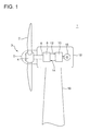
- FIG.1 is an illustration of a wind turbine generator according to an embodiment.
- a wind turbine generator 1 is provided with a rotor 3 formed by at least one blade 2 and a hub 4.
- the hub 4 may be covered by a hub cover (a spinner) 5.
- a hydraulic pump 8 is connected to the rotor 3 via a rotation shaft 6.
- a hydraulic motor 10 is connected via a high pressure oil line 12 and a low pressure oil line 14. More specifically, an outlet of the hydraulic pump 8 is connected to an inlet of the hydraulic motor 10 via the high pressure oil line 12 while an inlet of the hydraulic pump 8 is connected to an outlet of the hydraulic motor 10 via the low pressure oil line 14.
- the hydraulic pump 8 is driven by the rotation shaft 6 to pressurize operating oil, thereby generating high pressure operating oil (pressurized oil).
- the pressurized oil generated by the hydraulic pump 8 is supplied to the hydraulic motor 10 via the high pressure oil line 12 to drive the hydraulic motor 10.
- the operating oil having performed work in the hydraulic motor 10 becomes low pressure operating oil.
- the low pressure operating oil is returned to the hydraulic pump 8 via the low pressure oil line 14 provided between the outlet of the hydraulic motor 10 and the inlet of the hydraulic pump 8.
- the hydraulic transmission is configured to include the hydraulic pump 8 and the hydraulic motor 10.
- a generator 16 is connected to the hydraulic motor 10.
- the generator 16 is a synchronous generator which is connected to a grid and configured to be driven by the hydraulic motor 10.
- rotation shaft 6 is at least in part covered by a nacelle 18 installed on a tower 19.
- the hydraulic pump 8, the hydraulic motor 10 and the generator 16 are placed in the nacelle 18.
- At least one of the hydraulic pump 8 or the hydraulic motor 10 is a hydraulic machine of a radial piston type, which is described below.
- FIG.2 is a cross-sectional view of the hydraulic machine according to an embodiment, taken along a radial direction.
- FIG.3 is a cross-sectional view of a configuration in the periphery of a cylinder of the hydraulic machine according to an embodiment.
- a hydraulic machine illustrated in FIG.2 is provided with a plurality of cylinders 22, a plurality of pistons 24 respectively provided in the plurality of cylinders 22 and a plurality of rollers 26 respectively provided for the plurality of pistons 24.
- the hydraulic machine 20 is further provided with a rotation shaft 30 and a cam 32 configured to rotate with the rotation shaft 30.
- an annular outward cam 32 is provided on an outer circumferential side of the rotation shaft 30. Further, on an outer circumferential side of the outward cam 32, the cylinders 22, the pistons 24 and the rollers 26 are arranged.
- the outward cam refers to a cam having a cam surface contacting the rollers 26 on the outer circumferential side of the cam.
- an annular inward cam 32 is provided on an inner circumferential side of the rotation shaft 30, and the cylinders 22, the pistons 24 and the rollers 26 are arranged on the inner circumferential side of the inward cam 32.
- the inward cam refers to a cam having the cam profile contacting the rollers 26 on the inner circumferential side.
- the plurality of cylinders 22 is arranged in a cylinder block 21 in the circumferential direction of the hydraulic machine 20.
- the cylinder 22 is formed by a cylinder sleeve 23 inserted in a sleeve hole 21H of the cylinder block 21.
- the cylinder 22 is directly formed in the cylinder block 21 without using the cylinder sleeve 23.
- the cylinder block 21 may be separable into a plurality of segments 21S in the circumferential direction of the hydraulic machine 20.
- Each of the pistons 24 is slidably provided in each of the cylinders 22. Each of the pistons 24 is guided by each of the cylinders 22 to reciprocate between a bottom dead center and a top dead center along a center axis of the cylinder 22. In response to the reciprocating motion of the piston 24, volume of a hydraulic chamber 25 surrounded by each of the cylinders 22 and each of the pistons 24 changes cyclically.
- the reciprocating motion of the piston 24 which accompanies cyclic volume change of the hydraulic chamber 25 is convertible to a rotational motion of the cam 32, and vice versa.
- the rotational motion of the cam 32 rotating with the rotation shaft 30 of the hydraulic machine 20 is converted into reciprocating motion of the piston 24 and the volume of the hydraulic chamber 25 changes cyclically to generate high pressure operating oil (pressurized oil) in the hydraulic chamber 25.
- the hydraulic machine 20 is the hydraulic motor 10
- the reciprocating motion of the piston 24 in response to feeding of the pressurized oil into the hydraulic chamber 25 and then the reciprocating motion is converted into the rotational motion of the cam 32.
- the rotation shaft 30 of the hydraulic machine 20 rotates with the cam 32.
- the energy is converted between rotational energy (mechanical energy) of the rotation shaft 30 of the hydraulic machine 20 and fluid energy of the operating oil, and hence the hydraulic machine 20 is capable of functioning as the hydraulic pump 8 or the hydraulic motor 10 as desired.
- Each of the rollers 36 engages with each of the pistons 24 to freely rotate around a rotation axis of the roller 26.
- Each of the rollers 36 contacts a cam surface 33 of the cam 32.
- the cam 32 rotates with the rotation shaft 30 around the center O of the cam 32 (the center axis of the hydraulic machine 20)
- each of the rollers 26 travels on the cam surface 33 of the cam 32 while rotating around the rotation axis A of the roller 26.
- the cam surface 33 of the cam 32 is formed by a plurality of lobes 34 disposed along the circumferential direction of the hydraulic chamber 20. Each of the lobes 34 projects toward the cylinder 22. Each of the lobes 34 is formed by a smooth curve passing through a pair of bottom points 38 and one vertex point 36 disposed between the pair of bottom points 38. The vertex point 36 and the bottom point 38 of the lobe 34 are points on the cam surface 33 at which the distance from the rotation axis O of the hydraulic machine 20 is the largest or the smallest. The vertex point 36 is disposed nearer to the cylinder 22 than the bottom point 38.
- the vertex point 36 of the lobe 34 is a point on the cam surface 33 corresponding to a top dead center in a cycle of reciprocating motion of the piston 24.
- the bottom point 38 of the lobe 34 is a point on the cam surface 33 corresponding to a bottom dead center in the cycle of reciprocating motion of the piston 24.
- the cylinders 22 are arranged on the outer circumferential side of the outward cam 32, and the distance (a cam diameter) from the center axis O of the cam 32 (the rotation axis of the hydraulic machine 20) is the largest at the vertex point 36 of the lobe 34 while the distance (the cam diameter) from the center axis O is the smallest at the bottom point 38 of the lobe 34.
- the distance from the center axis O to the cam surface 33 is the smallest at the vertex point 36 of the lobe 34 and the distance from the center axis O to the cam surface 33 is the greatest at the bottom point 38 of the lobe 34. Further, at the vertex point 36 and the bottom point 38 of each of the lobes 34, a normal line to the cam surface 33 coincides with the radial direction of the hydraulic machine 20.
- the hydraulic machine 30 is further provided with a low pressure valve 40 provided between each of the hydraulic chambers 25 and the low pressure oil line 14, and a high pressure valve 50 provided between each of the hydraulic chambers 25 and the high pressure oil line 12.
- the hydraulic machine 20 is a hydraulic pump
- the low pressure valve 40 is used for supplying the low pressure operating oil to the hydraulic chamber 25 from the low pressure oil line 14
- the high pressure valve 50 is used for supplying the high pressure operating oil generated in the hydraulic chamber 25 to the high pressure line 12.
- the low pressure valve 40 may be a normal open solenoid valve including a first seat 41, a first valve element 42 configured to contact the first seat 41, a first stem 44 coupled to the first valve element 42, a solenoid 46 configured to generate magnetic force for driving the first stem 44, and a first biasing member 48 for biasing the first valve element 42 to a side opposite to the first seat 41.
- the solenoid 46 by energizing the solenoid 46, the first stem 44 moves against a biasing force of the first biasing member 48 by a magnetic force of the solenoid 46, the first valve element 42 contacts the first valve seat 41, and the low pressure valve 40 is closed.
- the first valve element 42 may be a face-sealing poppet valve element.
- the high pressure valve 50 may be a check valve, as illustrated in FIG.3 , including a second seat 51, a second valve element 52 contactable with the second seat 51 and a second biasing member 58 for biasing the second valve element 52 toward the second seat 51.
- the pressure in the hydraulic chamber 25 rises and a pressure difference between two sides of the second valve element 52 exceeds the biasing force of the second biasing member 58, the pressure difference causes the second valve element 52 to move away from the second seat 51, and the high pressure valve 50 is opened.
- the second valve element 52 may be a spherical valve element as illustrated in FIG.3 .
- FIG.4 is an oblique view of the cam, illustrating a polishing direction of the cam surface according to one embodiment.
- polishing direction of the cam surface 33 of the cam 32 is different from the rotation direction of the rotation shaft O of the hydraulic machine 20.
- polishing includes one of or combination of at least two of mechanical polishing, chemical polishing or electrical polishing.
- the polishing direction of the cam surface 33 is along the rotation shaft O of the hydraulic machine 20 as one example.
- the cam 32 undergoes grinding using a grinding material to be formed into shape, and then the cam surface 33 undergoes polishing which includes rough-polishing and final polishing (e.g. buff polishing) using a polishing material.
- the rotating polishing material is placed against the cam surface 33 to smooth the cam surface 33.
- the polishing direction (the rotation direction of the polishing material) is set different from the rotation direction of the rotation shaft O.
- the polishing material is moved in the above described direction so that minute grooves formed on the cam surface 33 by polishing are ultimately in the direction different from the rotation direction of the rotation shaft O.
- an operating direction of the grinding material may be set different from the rotation direction of the rotation shaft O.
- the cam surface 33 may undergo treatment such as chemical solution and power spraying.
- the cam surface 33 may be polished to a surface roughness Ra of not greater than 0.06.
- dimples may be formed on the cam surface 33, or the cam surface 33 may possess isotropy as described later in details.
- regular polishing may, of course, be performed.
- the polishing direction of the cam surface 33 coincides with the rotation direction of the rotation shaft O
- the direction of the minute groves formed by polishing coincides with a rolling direction of the roller 26 with respect to the cam surface 33.
- lubricating oil leaks along the minute grooves formed by polishing, which makes it difficult to retain the oil film of sufficient thickness in a contact part of the cam surface 33 and the roller 26. Therefore, by setting the polishing direction of the cam surface 33 different from the rotation direction of the rotation shaft O, the lubricating oil is retained in the minute grooves, thereby maintaining the oil film on the cam surface 33 and keeping favorable lubricity between the cam surface 33 and the roller 26. As a result, the deterioration of the cam surface can be reduced and the life of the cam 32 can be improved.
- FIG.5 is an oblique view of the cam illustrating a polishing direction of the cam surface according to another embodiment.
- the polishing direction of the cam surface 33 of the cam 32 includes a first direction which is oblique to the rotation shaft O of the hydraulic machine 20 and a second direction which intersects the first direction and is oblique to the rotation shaft O.
- the oil film can be reliably formed on the contact part of the cam surface 33 and the roller 26, and the lubricity between the cam 32 and the roller 26 can be favorably maintained.
- the polishing direction of the cam surface 33 of the cam 32 may possess isotropy.
- the cam surface 33 is immersed in solution for smoothing treatment in which the cam surface 33 is dissolved by chemical reaction.
- the cam surface 33 which possesses isotropy without a particular polishing direction can be obtained.
- the oil film can be reliably formed on the contact part of the cam surface 33 and the roller 26 and the lubricity between the cam 32 and the roller 26 can be favorably maintained.
- a plurality of dimples may be formed on the cam surface 33 of the cam 32. For instance, after forming the minute groove in the direction different from the rotation direction of the rotation shaft O by rough-polishing, the surface of the cam surface 33 may be shaved by final polishing to form the dimples thereon.
- the lubricating oil can be retained in the plurality of dimples formed on the cam surface 33, the oil film can be reliably formed on the contact part of the cam surface 33 and the roller 26, and the lubricity between the cam 32 and the roller 26 can be favorably maintained.
- the cam surface 33 of the cam 32 has a Brinell hardness of not less than 600.
- the cam surface 33 of the cam 32 has a Brinell hardness of not greater than 800.
- the cam surface 33 has the surface roughness Ra of not less than 0.1 and not greater than 0.3.
- the surface roughness is arithmetical mean deviation specified in JIS B0601.
- the lubricity between the cam 32 and the roller 26 can be favorably maintained while retaining the lubricating oil of sufficient thickness on the cam surface 33 to maintain seizure resistance.
- the hydraulic machine 20 is configured so that the piston 24 is caused to reciprocate in the cylinder 22 when the roller 26 rolls on the cam surface 33. However, the roller 26 sometimes skids on the cam surface 33. This could result in seizure or smearing.
- a friction coefficient between the roller 26 and the cam surface 33 is set larger than a friction coefficient between the roller 26 and the piston 24 so that skidding does not occur between the cam surface 33 and the roller 26.
- the piston 24 is configured so that a hydrostatic bearing is formed on a roller sliding surface 243 of the piston 24.
- the hydrostatic bearing operates by supplying the operating oil in the hydraulic chamber 25 to hydrostatic pads 60A, 60B provided on the roller sliding surface 243 of the piston 24.
- the configuration of the hydrostatic bearing is described later in details.
- roller sliding surface 243 of the piston 24 and the outer periphery of the roller 26 slide smoothly. Therefore, when the roller sliding surface 243 and the roller 26 are in fluid lubrication state, the roller 26 can roll on the cam surface 33 smoothly.
- the roller 26 can roll smoothly without skidding on the cam surface 33 even in the low pressure region LA, and it is possible to prevent occurrence of failure such as seizure and smearing.
- the piston 24 illustrated in FIG.6A is configured to include a hydraulic-chamber forming part 241 and a roller holding part 242.
- the hydraulic-chamber forming part 241 is configured to reciprocate in the cylinder 22.
- the hydraulic-chamber forming part 241 forms the hydraulic chamber 25 together with the cylinder 22.
- the roller holding part 242 holds the roller 26 rotatably and includes the roller sliding surface 243 which engages with the roller 26.
- the roller sliding surface 243 is formed as a curved surface with a curvature approximately equal to or slightly greater than that of the roller 26 to fit the outer periphery of the roller 26.
- the roller sliding surface 243 is arranged to partially surround the outer periphery of the roller 26.
- the piston 24 is configured to reciprocate in the cylinder 22 upon receiving a pressing force from the cam 32 via the roller 26.
- the roller holding part 242 may be formed with larger diameter than the hydraulic-chamber forming part 241.
- an inner passage 245 where the operating oil flows from the hydraulic chamber 25 is formed. More than one inner passage 245 may be formed in the piston 24. For instance, as illustrated in FIG.6A , two inner passages 245 are provided in the width direction of the roller 26 (in the depth direction of the drawing sheet).
- This inner passage 245 includes a passage portion 245A opening to the hydraulic chamber 25 at one end and being formed to penetrate the hydraulic-chamber forming part 241 in the axial direction of the piston 24 and a passage portion 245B communicating with the passage portion 245A at one end, penetrating the roller holding part 242 and opening to the roller sliding surface 243 at the other end.
- an orifice for regulating the flow of the operating oil supplied from the hydraulic chamber 25 may be provided.
- At least one hydrostatic pad 60A, 60B is provided on the roller sliding surface 243 of the piston 24.
- the hydrostatic pad 60A, 60B includes an annular groove 61A, 61B communicating with the hydraulic chamber 25 via the inner passage 245 formed in the piston 24 and a land 65A, 65B surrounded by the annular groove 61A, 61B.
- illustrated as one example is the case where a communication groove 62A, 62B is formed along the rotation direction of the roller 26 to transverse the annular groove 61A, 61B.
- two lands 65A, 65B are provided inside each annular groove 61A, 61B.
- the inner passage 245 communicates with supply ports 63A, 63B respectively provided on the communication grooves 62A, 62B.
- the operating oil is supplied from the hydraulic chamber 25 to the communication grooves 62A, 62B of the grooves 60A, 60B via the inner passage 245. Then, the operating oil supplied from the inner passage 245 is led to different parts of the annular grooves 61A, 61B via the communication grooves 62A, 62B.
- the hydrostatic bearing is formed on the roller sliding surface 243 of the piston 24. More specifically, when the roller 26 rotates, the operating oil in the annular grooves 61A, 61B and the communication grooves 62A, 62B is drawn to the roller sliding surface, thereby generating static pressure by a hydraulic pressure. This hydrostatic pressure supports the large load applied to the roller 26 from the cam 32. Then, for the amount of the operating oil drawn to the engagement surface 30 from the annular grooves 61A, 61B and the communication grooves 62A, 62B, the operating oil is replenished to the hydrostatic pads 60A, 60B so as to constantly obtain the hydrostatic pressure by the hydraulic pressure.
- the piston 24 may be provided with a hydrostatic pad 70 on a sliding surface of the piston 24 against the cylinder 22.
- the inner passage 246 where the operating oil flows from the hydraulic chamber 25 is provided in the piston 24.
- This inner passage 246 includes a passage portion 246A opening to the hydraulic chamber 25 at one end and being formed to penetrate the hydraulic-chamber forming part 241 in the axial direction of the piston 24 and a passage portion 246B communicating with the passage portion 246A at one end, penetrating the roller holding part 242 and opening at the other end to the surface of the piston 24 sliding against the inner periphery of the cylinder 22.
- a hydrostatic pad 70 including an annular groove may be provided on the surface of the piston 24 sliding against the inner periphery of the cylinder 22, and the operating oil is supplied to the hydrostatic pad 70 from the hydraulic chamber 25 via the inner passage 246.
- the hydrostatic bearing is formed in this manner between the inner periphery of the cylinder 22 and the outer periphery of the piston 24.
- FIG.7A and FIG.7B in one embodiment, on the cam surface 33, there are a the high pressure region HA having a high contact load between the cam 32 and the roller 26 and the low pressure region LA having a low contact load between the cam 32 and the roller 26.
- FIG.7A is a graph showing a cam profile and the contact load according to an embodiment.
- FIG.7B is a graph showing the cam profile, a friction coefficient between the roller and the cam and a friction coefficient between the roller and the piston according to an embodiment.
- the roller 26 is at the vertex point 36 of the cam surface 33.
- the vertex point 36 is a point on the cam surface 33 at which the cam diameter is the largest.
- the roller 26 is at the bottom point 38 of the cam surface 33.
- the bottom point 38 is a point on the cam surface 33 at which the cam diameter is the smallest.
- the high pressure region HA is on a downstream side of each lob 34 with respect to the vertex point 36 in the rotation direction of the cam 32
- the low pressure region LA is on an upstream side of each lobe 34 with respect to the vertex point 36 in the rotation direction of the cam 32.
- the high pressure region HA and the low pressure region LA may be defined with respect to a boundary point 37 which is displaced from the vertex point 36 toward the downstream side in a traveling direction of the roller 26 on the cam surface 33.
- the hydraulic machine 20 is the hydraulic motor
- the piston 24 when the piston 24 is at a position in the high pressure region HA of the cam surface 33, basically the piston 24 is traveling from the top dead center toward the bottom dead center and the pressure of the operating oil in the hydraulic chamber 25 is high.
- the piston 24 when the piston 24 is at a position in the low pressure region LA of the cam surface 33, basically the roller 26 is traveling from the bottom dead center toward the top dead center and the pressure of the operating oil in the hydraulic chamber 25 is low.
- the high pressure region HA is on the upstream side of each lob 34 with respect to the vertex point 36 in the rotation direction of the cam 32, whereas the low pressure region LA is on the downstream side of each lobe 34 with respect to the vertex point 36 in the rotation direction of the cam 32.
- the low pressure region LA of the cam surface 33 has a surface roughness Ra which is greater than that of the high pressure region HA.
- the operating oil is positively supplied to the sliding part between the piston 24 and the roller 26, thereby significantly reducing the friction coefficient between the roller 26 and the piston 24.
- the roller 26 is in the low pressure region LA of the cam surface 33, the operating oil pressure is low in the hydraulic chamber 25 and thus the operating oil is not sufficiently supplied to the sliding part between the piston 24 and the roller 26. Hence, the friction coefficient between the roller 26 and the piston 24 is still large.
- skidding is likely to occur between the roller 26 and the cam surface 33 when the roller 26 is at a position in the low pressure region LA of the cam surface 33.
- the surface roughness Ra of the low pressure region LA is set greater than that of the high pressure region HA.
- the friction coefficient of each region is set as illustrated in FIG.7B . More specifically, the friction coefficient between the cam 32 and the roller 26 (cam-roller friction coefficient in FIG.7B ) in the high pressure region HA is originally set larger than the friction coefficient between the cam 32 and the roller 26 in the low pressure region LA, corresponding to the high contact load between the cam 32 and the roller 26. In this case, the friction coefficient between the roller 26 and the piston 24 (piston-roller friction coefficient in FIG.7B ) become significantly small as the hydrostatic bearing functions properly. As a result, the friction coefficient between the cam 32 and the roller 26 is larger than the friction coefficient between the piston 24 and the roller 26 and hence, the roller 26 smoothly rolls on the cam surface 33.
- the contact load between the cam 32 and the roller 26 decreases.
- the surface roughness Ra of the cam surface 33 in the low pressure region LA is set greater than the high pressure region HA and thus, the friction coefficient between the cam 32 and the roller 26 increases.
- the friction coefficient between the cam 32 and the roller 26 is larger than the friction coefficient between the piston 24 and the roller 26 and hence, the roller 26 can still roll smoothly on the cam surface 33 even in the low pressure region LA.
- the polishing direction of the cam surface 33 different from the rotation direction of the rotation shaft O, the lubricating oil is retained in the minute grooves formed on the cam surface 33 by polishing, thereby making it possible to retain the oil film on the cam surface 33 and to keep favorable lubricity between the cam surface 33 and the roller 26.
- the deterioration of the cam surface 33 can be suppressed and the life of the cam 32 can be improved.
Landscapes
- Engineering & Computer Science (AREA)
- Mechanical Engineering (AREA)
- General Engineering & Computer Science (AREA)
- Chemical & Material Sciences (AREA)
- Combustion & Propulsion (AREA)
- Life Sciences & Earth Sciences (AREA)
- Sustainable Development (AREA)
- Sustainable Energy (AREA)
- Power Engineering (AREA)
- Hydraulic Motors (AREA)
- Wind Motors (AREA)
- Reciprocating Pumps (AREA)
Abstract
Description
- The present invention relates to a hydraulic machine of a radial piston type, a hydraulic transmission and a wind turbine generator.
- Conventionally known is a hydraulic machine of a radial piston type having a plurality of pistons that are radially arranged.
- For instance, disclosed in
Patent Document 1 is a hydraulic machine of a radial piston type provided with a piston reciprocating in a cylinder, a roller rotatably attached to the piston and a ring cam having a cam surface on which the roller rolls. Another radial piston hydraulic machine is disclosed inPatent Document 2, which functions as a drive train of a wind turbine generator. -
GB 2484890 A -
GB 2482879 A - In a hydraulic machine of a radial piston type, lubricating oil is normally supplied to a space between a roller and a cam surface to suppress deterioration of the cam surface. Normally, the cam surface is formed into a smooth surface by polishing to reduce friction against the roller. There are, however, minute grooves formed during polishing. Thus, the lubricating oil to be maintained between the cam surface and the roller may leak, resulting in insufficient lubricating oil maintained between the cam surface and the roller. When an oil film on the cam surface becomes thin, the surface is prone to damage, and this could reduce the cam life.
- In this aspect, there is no disclosure regarding lubricity between the roller and the cam in
Patent Documents - An object of at least one embodiment of the present invention is to provide a hydraulic machine of a radial piston type, a hydraulic transmission and a wind turbine generator which make it possible to maintain excellent lubricity between the cam surface and the roller and to enhance the cam life.
- A hydraulic machine of a radial piston type according to at least one embodiment of the present invention, comprises:
- a plurality of pistons arranged along a radial direction of the hydraulic machine;
- a plurality of rollers provided rotatably for the plurality of pistons, respectively; and
- a cam having a cam surface contacting the plurality of rollers, and
- the cam is configured rotatable around a rotation shaft of the hydraulic machine relative to the plurality of rollers, and
- a polishing direction of the cam surface is different from a rotation direction of the rotation shaft.
- According to the above hydraulic machine, it is possible to retain lubricating oil between the cam surface and the roller, and to maintain favorable lubricity between the cam surface and the roller.
- In the case where the polishing direction of the cam surface coincides with the rotation direction of the rotation shaft, the direction of the minute grooves formed by polishing coincides with a rolling direction of the roller with respect to the cam surface. Thus, when the roller rolls on the cam surface, the lubricating oil escapes along the minute grooves formed by polishing, which makes it difficult to retain the oil film of sufficient thickness in a contact part of the cam surface and the roller. Therefore, by setting the polishing direction of the cam surface different from the rotation direction of the rotation shaft, the lubricating oil is retained in the minute grooves, thereby retaining the oil film on the cam surface and maintaining favorable lubricity between the cam surface and the roller. As a result, the deterioration of the cam surface can be reduced and the cam life can be improved.
- Further, "the polishing direction of the cam surface is different from the rotation direction of the rotation shaft" means that the polishing direction does not include a direction which coincides with the rotation direction of the rotation shaft, and includes the case where there is not one or more particular directions recognized as a polishing direction (the case where the polishing direction of the cam surface possesses isotropy).
- In some embodiments, a friction coefficient between the roller and the cam surface is set larger a friction coefficient between the roller and the piston so that skidding does not occur between the cam surface and the roller.
- The above hydraulic machine is configured so that the roller rolls on the cam surface. However, the roller skids sometimes on the
cam surface 33. This could result in seizure or smearing. Therefore, in some embodiments, a friction coefficient between the roller and the cam surface is set larger a friction coefficient between the roller and the piston so that skidding does not occur between the cam surface and the roller. As a result, the roller can smoothly roll on the cam surface without skidding, and thus it is possible to prevent occurrence of failure such as seizure and smearing. Therefore, the cam life can be further enhanced. - In one embodiment, the polishing direction of the cam surface is a direction along the rotation shaft.
- As a result, the oil film can be reliably formed on a contact part of the cam surface and the roller, and the lubricity between the cam and the roller can be favorably maintained.
- In another embodiment, the polishing direction of the cam surface includes a first direction which is oblique to the rotation shaft and a second direction which intersects the first direction and is oblique to the rotation shaft.
- As a result, the oil film can be reliably formed on a contact part of the cam surface and the roller, and the lubricity between the cam and the roller can be favorably maintained.
- In yet another embodiment, the polishing direction of the cam surface possesses isotropy.
- As a result, the oil film can be reliably formed on a contact part of the cam surface and the roller, and the lubricity between the cam and the roller can be favorably maintained.
- In some embodiments, a plurality of dimples is formed on the cam surface.
- As a result, the lubricating oil can be retained in the plurality of dimples formed on the cam surface, the oil film can be reliably formed on the contact part of the cam surface and the roller, and the lubricity between the cam and the roller can be favorably maintained.
- In one embodiment, the cam surface has a Brinell hardness of not less than 600.
- As a result, it is possible to achieve the configuration in which the cam surface is not damaged easily, and hence it is possible to further improve the cam life.
- In one embodiment, the cam surface has a Brinell hardness of not greater than 800.
- In some embodiments, the cam surface has a surface roughness Ra of not less than 0.1 and not greater than 0.3.
- Generally, to suppress friction in a contact part between two objects, it is considered desirable to improve lubricity by smoothing the surface. Thus, the smaller the surface roughness Ra of the cam surface is, the longer the cam life becomes. However, according to knowledge of the inventors of the present invention, when the surface roughness of the cam surface is less than 0.1, the lubricity in the contact part between the cam surface and the roller is improved but it becomes difficult to retain the lubricating oil on the cam surface. As a result, it becomes difficult to maintain sufficient oil film thickness, resulting in deteriorated seizure-resistance. Further, when the surface roughness of the cam surface is greater than 0.3, the sufficient oil fill thickness can be obtained but the lubricity in the contact part between the cam surface and the roller declines. Therefore, as described in the above embodiment, by setting the surface roughness Ra of the cam surface to be not less than 0.1 and not greater than 0.3, the lubricity between the cam surface and the roller can be favorably maintained while retaining the lubricating oil of sufficient thickness on the cam surface to maintain seizure resistance.
- In some embodiments, the cam includes a high pressure region of the cam surface and a low pressure region of the cam surface, the high pressure region contacting the roller corresponding to a hydraulic chamber surrounded by the piston and the cylinder and undergoing pressure increase in the hydraulic chamber in a reciprocation cycle of the piston reciprocating in the cylinder, the low pressure region contacting the roller corresponding to a hydraulic chamber surrounded by the piston and the cylinder and undergoing pressure decrease in the hydraulic chamber in the reciprocation cycle, and the low pressure region has a surface roughness Ra which is greater than that of the high pressure region.
- In the case where the sliding part between the piston and the roller is lubricated with the operating oil from the hydraulic chamber, while the roller is in the high pressure region of the cam surface, the operating oil is positively supplied to the sliding part between the piston and the roller, thereby significantly reducing the friction coefficient of the roller with respect to the piston. In contrast, while the roller is in the low pressure region of the cam surface, the operating oil pressure is low in the hydraulic chamber, and thus the operating oil is not sufficiently supplied to the sliding part between the piston and the roller. Hence, the friction coefficient between the roller and the piston remains large. Therefore, compared to the case when the roller is at a position in the high pressure region of the cam surface, skidding is likely to occur between the roller and the cam surface when the roller is at a position in the low pressure region of the cam surface.
- Therefore, by setting the surface roughness of the low pressure region greater than that of the high pressure region, the friction efficient between the roller and the cam surface (low pressure region) can be sufficiently secured and thus, it is possible to prevent skidding between the roller and the cam, which easily happens when the roller is in the low pressure region of the cam surface. This improves the durability against smearing, seizure, etc. which is caused by skidding. By selectively reducing the surface roughness in the high pressure region with distribution in the surface roughness Ra of the cam surface, in comparison to the case where the surface roughness is uniform throughout the cam surface, it is possible to avoid excessive designing, to prevent size increase of the hydraulic machine, and to improve reliability of the hydraulic machine.
- A hydraulic transmission according to at least one embodiment of the present invention, comprises:
- a hydraulic pump configured to be driven by rotation of a rotation shaft; and
- a hydraulic motor configured to be driven by pressurized oil generated by the hydraulic pump, and
- at least one of the hydraulic pump or the hydraulic motor is a hydraulic machine of a radial piston type, and
- the hydraulic machine comprises a plurality of pistons arranged along a radial direction of the hydraulic machine, a plurality of rollers provided rotatably for the plurality of pistons, respectively, and a cam having a cam surface contacting the plurality of rollers, the cam being configured rotatable around a rotation shaft of the hydraulic machine relative to the plurality of rollers, a polishing direction of the cam surface being different from a rotation direction of the rotation shaft.
- According to the above hydraulic transmission, by making the polishing direction of the cam surface different from the rotation direction of the rotation shaft, the lubricating oil is retained in the minute grooves formed on the cam surface by polishing, thereby making it possible to retain the oil film on the cam surface and to keep favorable lubricity between the cam surface and the roller. As a result, the deterioration of the cam surface can be suppressed and the cam life can be improved.
- In some embodiments, a friction coefficient between the roller and the cam surface is set larger than a friction coefficient between the roller and the piston so that skidding does not occur between the cam surface and the roller.
- With the above configuration in which the friction coefficient between the roller and the cam surface is set larger than the friction coefficient between the roller and the piston so that skidding does not occur between the cam surface and the roller, the roller can smoothly roll on the cam surface without skidding, and thus it is possible to prevent occurrence of failure such as seizure and smearing. Therefore, the cam life can be enhanced.
- A wind turbine generator according to at least one embodiment of the present invention comprises:
- at least one blade;
- a hub on which the at least one blade is mounted;
- a hydraulic pump configured to be driven by rotation of the hub;
- a hydraulic motor configured to be driven by pressurized oil generated by the hydraulic pump; and
- a generator configured to be driven by the hydraulic motor, and
- at least one of the hydraulic pump or the hydraulic motor is a hydraulic machine of a radial piston type, and
- the hydraulic machine comprises a plurality of pistons arranged along a radial direction of the hydraulic machine, a plurality of rollers provided rotatably for the plurality of pistons, respectively, and a cam having a cam surface contacting the plurality of rollers, the cam being configured rotatable around a rotation shaft of the hydraulic machine relative to the plurality of rollers, a polishing direction of the cam surface being different from a rotation direction of the rotation shaft.
- According to the above wind turbine generator, by making the polishing direction of the cam surface different from the rotation direction of the rotation shaft, the lubricating oil is retained in the minute grooves formed on the cam surface by polishing, thereby making it possible to retain the oil film on the cam surface and to keep favorable lubricity between the cam surface and the roller. As a result, the deterioration of the cam surface can be suppressed and the cam life can be improved.
- In some embodiments, a friction coefficient between the roller and the cam surface is set larger than a friction coefficient between the roller and the piston so that skidding does not occur between the cam surface and the roller.
- With the above configuration in which the friction coefficient between the roller and the cam surface is set larger than the friction coefficient between the roller and the piston so that skidding does not occur between the cam surface and the roller, the roller can smoothly roll on the cam surface without skidding, and thus it is possible to prevent occurrence of failure such as seizure and smearing. Therefore, the cam life can be enhanced.
- According to at least one embodiment of the present invention, by making the polishing direction of the cam surface different from the rotation direction of the rotation shaft, the lubricating oil is retained in the minute grooves formed on the cam surface by polishing, thereby making it possible to retain the oil film on the cam surface and to keep favorable lubricity between the cam surface and the roller. As a result, the deterioration of the cam surface can be suppressed and the cam life can be improved.
-
- [
FIG.1] FIG.1 is an illustration of a wind turbine generator according to an embodiment. - [
FIG.2] FIG.2 is a cross-sectional view of a hydraulic machine according to an embodiment, taken along a radial direction. - [
FIG.3] FIG.3 is a cross-sectional view of a configuration in the periphery of a cylinder of the hydraulic machine according to an embodiment. - [
FIG.4] FIG.4 is an oblique view of a cam illustrating a polishing direction of a cam surface according to an embodiment. - [
FIG.5] FIG.5 is an oblique view of the cam illustrating a polishing direction of the cam surface according to another embodiment. - [
FIG.6A] FIG.6A is a cross-sectional view of a piston according to an embodiment. - [
FIG.6B] FIG.6B is a view of the piston ofFIG.6A , taken outwardly in the radial direction of the cam. - [
FIG.7A] FIG.7A is a graph showing a cam profile and a contact load according to an embodiment. - [
FIG.7B] FIG.7B is a graph showing the cam profile, a cam/roller friction coefficient and a piston/roller friction coefficient according to an embodiment. - Embodiments of the present invention will now be described in detail with reference to the accompanying drawings. It is intended, however, that unless particularly specified, dimensions, materials, shapes, relative positions and the like of components described in the embodiments shall be interpreted as illustrative only and not limitative of the scope of the present invention.
- In the following embodiments, a wind turbine generator is described as one example of an apparatus to which a hydraulic machine or a hydraulic transmission is applied. The hydraulic machine or the hydraulic transmission of the present invention may, however, be used for other types of renewable energy power generating apparatuses such as a tidal current power generating apparatus, an ocean current power generating apparatus and a river current power generating apparatus. Further, the hydraulic machine or the hydraulic transmission of the present invention may also be applied to other apparatuses such as construction machines and its use is not particularly restricted.
- Hereinafter, embodiments regarding a hydraulic machine provided with an outward cam are mainly described. This is, however, not restrictive and the hydraulic machine may be provided with an inward cam. In such case, the embodiments of the present invention may include the case where description regarding the directions mentioned below is reversed appropriately. Moreover, the case where the cam rotates is illustrated. This is, however, not restrictive and the cam may be fixed while the cylinder and the piston are configured to rotate.
-
FIG.1 is an illustration of a wind turbine generator according to an embodiment. As illustrated in the drawing, awind turbine generator 1 is provided with arotor 3 formed by at least oneblade 2 and ahub 4. Thehub 4 may be covered by a hub cover (a spinner) 5. - In one embodiment, a
hydraulic pump 8 is connected to therotor 3 via arotation shaft 6. To thehydraulic pump 8, ahydraulic motor 10 is connected via a highpressure oil line 12 and a lowpressure oil line 14. More specifically, an outlet of thehydraulic pump 8 is connected to an inlet of thehydraulic motor 10 via the highpressure oil line 12 while an inlet of thehydraulic pump 8 is connected to an outlet of thehydraulic motor 10 via the lowpressure oil line 14. Thehydraulic pump 8 is driven by therotation shaft 6 to pressurize operating oil, thereby generating high pressure operating oil (pressurized oil). The pressurized oil generated by thehydraulic pump 8 is supplied to thehydraulic motor 10 via the highpressure oil line 12 to drive thehydraulic motor 10. The operating oil having performed work in thehydraulic motor 10 becomes low pressure operating oil. The low pressure operating oil is returned to thehydraulic pump 8 via the lowpressure oil line 14 provided between the outlet of thehydraulic motor 10 and the inlet of thehydraulic pump 8. In this embodiment, the hydraulic transmission is configured to include thehydraulic pump 8 and thehydraulic motor 10. - A
generator 16 is connected to thehydraulic motor 10. In one embodiment, thegenerator 16 is a synchronous generator which is connected to a grid and configured to be driven by thehydraulic motor 10. - Further, the
rotation shaft 6 is at least in part covered by anacelle 18 installed on atower 19. In one embodiment, thehydraulic pump 8, thehydraulic motor 10 and thegenerator 16 are placed in thenacelle 18. - In some embodiments, at least one of the
hydraulic pump 8 or thehydraulic motor 10 is a hydraulic machine of a radial piston type, which is described below. -
FIG.2 is a cross-sectional view of the hydraulic machine according to an embodiment, taken along a radial direction.FIG.3 is a cross-sectional view of a configuration in the periphery of a cylinder of the hydraulic machine according to an embodiment. - A hydraulic machine illustrated in
FIG.2 is provided with a plurality ofcylinders 22, a plurality ofpistons 24 respectively provided in the plurality ofcylinders 22 and a plurality ofrollers 26 respectively provided for the plurality ofpistons 24. Thehydraulic machine 20 is further provided with arotation shaft 30 and acam 32 configured to rotate with therotation shaft 30. - In an embodiment illustrated in
FIG.2 andFIG.3 , an annularoutward cam 32 is provided on an outer circumferential side of therotation shaft 30. Further, on an outer circumferential side of theoutward cam 32, thecylinders 22, thepistons 24 and therollers 26 are arranged. Herein, the outward cam refers to a cam having a cam surface contacting therollers 26 on the outer circumferential side of the cam. In another embodiment, an annularinward cam 32 is provided on an inner circumferential side of therotation shaft 30, and thecylinders 22, thepistons 24 and therollers 26 are arranged on the inner circumferential side of theinward cam 32. Herein, the inward cam refers to a cam having the cam profile contacting therollers 26 on the inner circumferential side. - The plurality of
cylinders 22 is arranged in acylinder block 21 in the circumferential direction of thehydraulic machine 20. In one embodiment, as illustrated inFIG.3 , thecylinder 22 is formed by acylinder sleeve 23 inserted in asleeve hole 21H of thecylinder block 21. In another embodiment, thecylinder 22 is directly formed in thecylinder block 21 without using thecylinder sleeve 23. Thecylinder block 21 may be separable into a plurality ofsegments 21S in the circumferential direction of thehydraulic machine 20. - Each of the
pistons 24 is slidably provided in each of thecylinders 22. Each of thepistons 24 is guided by each of thecylinders 22 to reciprocate between a bottom dead center and a top dead center along a center axis of thecylinder 22. In response to the reciprocating motion of thepiston 24, volume of ahydraulic chamber 25 surrounded by each of thecylinders 22 and each of thepistons 24 changes cyclically. - The reciprocating motion of the
piston 24 which accompanies cyclic volume change of thehydraulic chamber 25 is convertible to a rotational motion of thecam 32, and vice versa. - For instance, in the case where the
hydraulic machine 20 is thehydraulic pump 8, the rotational motion of thecam 32 rotating with therotation shaft 30 of thehydraulic machine 20 is converted into reciprocating motion of thepiston 24 and the volume of thehydraulic chamber 25 changes cyclically to generate high pressure operating oil (pressurized oil) in thehydraulic chamber 25. In contrast, in the case where thehydraulic machine 20 is thehydraulic motor 10, the reciprocating motion of thepiston 24 in response to feeding of the pressurized oil into thehydraulic chamber 25 and then the reciprocating motion is converted into the rotational motion of thecam 32. As a result, therotation shaft 30 of thehydraulic machine 20 rotates with thecam 32. - In this manner, with use of the
cam 32, the energy is converted between rotational energy (mechanical energy) of therotation shaft 30 of thehydraulic machine 20 and fluid energy of the operating oil, and hence thehydraulic machine 20 is capable of functioning as thehydraulic pump 8 or thehydraulic motor 10 as desired. - Each of the
rollers 36 engages with each of thepistons 24 to freely rotate around a rotation axis of theroller 26. Each of therollers 36 contacts acam surface 33 of thecam 32. When thecam 32 rotates with therotation shaft 30 around the center O of the cam 32 (the center axis of the hydraulic machine 20), each of therollers 26 travels on thecam surface 33 of thecam 32 while rotating around the rotation axis A of theroller 26. - The
cam surface 33 of thecam 32 is formed by a plurality oflobes 34 disposed along the circumferential direction of thehydraulic chamber 20. Each of thelobes 34 projects toward thecylinder 22. Each of thelobes 34 is formed by a smooth curve passing through a pair ofbottom points 38 and onevertex point 36 disposed between the pair ofbottom points 38. Thevertex point 36 and thebottom point 38 of thelobe 34 are points on thecam surface 33 at which the distance from the rotation axis O of thehydraulic machine 20 is the largest or the smallest. Thevertex point 36 is disposed nearer to thecylinder 22 than thebottom point 38. Thevertex point 36 of thelobe 34 is a point on thecam surface 33 corresponding to a top dead center in a cycle of reciprocating motion of thepiston 24. In contrast, thebottom point 38 of thelobe 34 is a point on thecam surface 33 corresponding to a bottom dead center in the cycle of reciprocating motion of thepiston 24. - In the embodiment illustrated in
FIG.2 andFIG.3 , thecylinders 22 are arranged on the outer circumferential side of theoutward cam 32, and the distance (a cam diameter) from the center axis O of the cam 32 (the rotation axis of the hydraulic machine 20) is the largest at thevertex point 36 of thelobe 34 while the distance (the cam diameter) from the center axis O is the smallest at thebottom point 38 of thelobe 34. In another embodiment where thecylinders 22 are arranged on the inner circumferential side of the inward cam, the distance from the center axis O to thecam surface 33 is the smallest at thevertex point 36 of thelobe 34 and the distance from the center axis O to thecam surface 33 is the greatest at thebottom point 38 of thelobe 34. Further, at thevertex point 36 and thebottom point 38 of each of thelobes 34, a normal line to thecam surface 33 coincides with the radial direction of thehydraulic machine 20. - In some embodiments, as illustrated in
FIG.3 , thehydraulic machine 30 is further provided with alow pressure valve 40 provided between each of thehydraulic chambers 25 and the lowpressure oil line 14, and ahigh pressure valve 50 provided between each of thehydraulic chambers 25 and the highpressure oil line 12. In the case where thehydraulic machine 20 is a hydraulic pump, thelow pressure valve 40 is used for supplying the low pressure operating oil to thehydraulic chamber 25 from the lowpressure oil line 14 and thehigh pressure valve 50 is used for supplying the high pressure operating oil generated in thehydraulic chamber 25 to thehigh pressure line 12. - The
low pressure valve 40, as illustrated inFIG.3 , may be a normal open solenoid valve including a first seat 41, afirst valve element 42 configured to contact the first seat 41, a first stem 44 coupled to thefirst valve element 42, asolenoid 46 configured to generate magnetic force for driving the first stem 44, and a first biasingmember 48 for biasing thefirst valve element 42 to a side opposite to the first seat 41. In this case, by energizing thesolenoid 46, the first stem 44 moves against a biasing force of the first biasingmember 48 by a magnetic force of thesolenoid 46, thefirst valve element 42 contacts the first valve seat 41, and thelow pressure valve 40 is closed. Further, by de-energizing thesolenoid 46, the first stem 44 moves and thefirst valve element 42 moves away from the first seat 41 by the biasing force of the first biasingmember 48, and thelow pressure valve 40 is opened. Thefirst valve element 42 may be a face-sealing poppet valve element. - In contrast, in the case where the
hydraulic machine 20 is the hydraulic pump, thehigh pressure valve 50 may be a check valve, as illustrated inFIG.3 , including a second seat 51, asecond valve element 52 contactable with the second seat 51 and a second biasing member 58 for biasing thesecond valve element 52 toward the second seat 51. In this case, when the pressure in thehydraulic chamber 25 rises and a pressure difference between two sides of thesecond valve element 52 exceeds the biasing force of the second biasing member 58, the pressure difference causes thesecond valve element 52 to move away from the second seat 51, and thehigh pressure valve 50 is opened. If the pressure difference between two sides of thesecond valve element 52 is smaller than the biasing force of the second biasing member 58, thesecond valve element 52 contacts the second seat 51 by the biasing force of the second biasing member 58, and thehigh pressure valve 50 is closed. Thesecond valve element 52 may be a spherical valve element as illustrated inFIG.3 . -
FIG.4 is an oblique view of the cam, illustrating a polishing direction of the cam surface according to one embodiment. - As illustrated in the drawing, in this embodiment, the polishing direction of the
cam surface 33 of thecam 32 is different from the rotation direction of the rotation shaft O of thehydraulic machine 20. Herein, polishing includes one of or combination of at least two of mechanical polishing, chemical polishing or electrical polishing. - In
FIG.4 , the polishing direction of thecam surface 33 is along the rotation shaft O of thehydraulic machine 20 as one example. Further, "the polishing direction of thecam surface 33 is different from the rotation direction of the rotation shaft O" means that the polishing direction does not include a direction which coincides with the rotation direction of the rotation shaft O, and also includes the case where there is not one or more particular directions recognized as a polishing direction (the case where the polishing direction of the cam surface possesses isotropy). For instance, in the case where thecam 32 is mechanically polished, thecam 32 undergoes grinding using a grinding material to be formed into shape, and then thecam surface 33 undergoes polishing which includes rough-polishing and final polishing (e.g. buff polishing) using a polishing material. In the polishing step, the rotating polishing material is placed against thecam surface 33 to smooth thecam surface 33. In this process, the polishing direction (the rotation direction of the polishing material) is set different from the rotation direction of the rotation shaft O. In the case of performing more than one polishing step including the rough-polishing and final polishing, in at least one of the polishing steps, the polishing material is moved in the above described direction so that minute grooves formed on thecam surface 33 by polishing are ultimately in the direction different from the rotation direction of the rotation shaft O. Alternatively, in the case of polishing thecam surface 33 to the extent that the minute grooves formed on thecam surface 33 in the grinding step still remain, an operating direction of the grinding material may be set different from the rotation direction of the rotation shaft O. Moreover, in the case of superfinishing thecam surface 33 in the final polishing step, thecam surface 33 may undergo treatment such as chemical solution and power spraying. In the superfinishing step, thecam surface 33 may be polished to a surface roughness Ra of not greater than 0.06. In this case, for the purpose of maintaining an oil film of sufficient thickness on thecam surface 33, dimples may be formed on thecam surface 33, or thecam surface 33 may possess isotropy as described later in details. In the superfinishing, regular polishing may, of course, be performed. - For instance, in the case where the polishing direction of the
cam surface 33 coincides with the rotation direction of the rotation shaft O, the direction of the minute groves formed by polishing coincides with a rolling direction of theroller 26 with respect to thecam surface 33. Thus, when theroller 26 rolls over thecam surface 33, lubricating oil leaks along the minute grooves formed by polishing, which makes it difficult to retain the oil film of sufficient thickness in a contact part of thecam surface 33 and theroller 26. Therefore, by setting the polishing direction of thecam surface 33 different from the rotation direction of the rotation shaft O, the lubricating oil is retained in the minute grooves, thereby maintaining the oil film on thecam surface 33 and keeping favorable lubricity between thecam surface 33 and theroller 26. As a result, the deterioration of the cam surface can be reduced and the life of thecam 32 can be improved. -
FIG.5 is an oblique view of the cam illustrating a polishing direction of the cam surface according to another embodiment. - As illustrated in the drawing, in another embodiment, the polishing direction of the
cam surface 33 of thecam 32 includes a first direction which is oblique to the rotation shaft O of thehydraulic machine 20 and a second direction which intersects the first direction and is oblique to the rotation shaft O. As a result, the oil film can be reliably formed on the contact part of thecam surface 33 and theroller 26, and the lubricity between thecam 32 and theroller 26 can be favorably maintained. - The polishing direction of the
cam surface 33 of thecam 32 may possess isotropy. For instance, thecam surface 33 is immersed in solution for smoothing treatment in which thecam surface 33 is dissolved by chemical reaction. As a result, thecam surface 33 which possesses isotropy without a particular polishing direction can be obtained. - In this manner, by configuring the
cam 32 so that the polishing direction of thecam surface 33 possesses isotropy, the oil film can be reliably formed on the contact part of thecam surface 33 and theroller 26 and the lubricity between thecam 32 and theroller 26 can be favorably maintained. - Further, a plurality of dimples may be formed on the
cam surface 33 of thecam 32. For instance, after forming the minute groove in the direction different from the rotation direction of the rotation shaft O by rough-polishing, the surface of thecam surface 33 may be shaved by final polishing to form the dimples thereon. - As a result, the lubricating oil can be retained in the plurality of dimples formed on the
cam surface 33, the oil film can be reliably formed on the contact part of thecam surface 33 and theroller 26, and the lubricity between thecam 32 and theroller 26 can be favorably maintained. - In some embodiments, the
cam surface 33 of thecam 32 has a Brinell hardness of not less than 600. - In one embodiment, the
cam surface 33 of thecam 32 has a Brinell hardness of not greater than 800. - As a result, it is possible to achieve the configuration in which the
cam surface 33 is not damaged easily, and hence it is possible to further improve the life of thecam 32. - In some embodiments, the
cam surface 33 has the surface roughness Ra of not less than 0.1 and not greater than 0.3. The surface roughness is arithmetical mean deviation specified in JIS B0601. - By setting the surface roughness Ra of the
cam surface 33 to be not less than 0.1 and not greater than 0.3, the lubricity between thecam 32 and theroller 26 can be favorably maintained while retaining the lubricating oil of sufficient thickness on thecam surface 33 to maintain seizure resistance. - The
hydraulic machine 20 is configured so that thepiston 24 is caused to reciprocate in thecylinder 22 when theroller 26 rolls on thecam surface 33. However, theroller 26 sometimes skids on thecam surface 33. This could result in seizure or smearing. - Therefore, in some embodiments, a friction coefficient between the
roller 26 and thecam surface 33 is set larger than a friction coefficient between theroller 26 and thepiston 24 so that skidding does not occur between thecam surface 33 and theroller 26. As a result, theroller 26 smoothly rolls on thecam surface 33 without skidding, and thus it is possible to prevent occurrence of failure such as seizure and smearing. Therefore, the life of thecam 32 can be further enhanced. - In one embodiment, as illustrated in
FIG.6A and FIG.6B , thepiston 24 is configured so that a hydrostatic bearing is formed on aroller sliding surface 243 of thepiston 24. The hydrostatic bearing operates by supplying the operating oil in thehydraulic chamber 25 tohydrostatic pads roller sliding surface 243 of thepiston 24. The configuration of the hydrostatic bearing is described later in details. - When the pressure of the operating oil in the
hydraulic chamber 25 is high, load capacity of thehydrostatic pads roller sliding surface 243 and theroller 26 are in fluid lubrication state. Therefore, the friction coefficient between theroller 26 and theroller sliding surface 243 becomes significantly low. Between thecam surface 33 and theroller 26, the lubricating oil is present but the hydrostatic bearing is not provided. Thus, when theroller sliding surface 243 and theroller 26 are in fluid lubrication state, the friction coefficient between theroller 26 and thecam surface 33 is normally larger than the friction coefficient between theroller 26 and the roller sliding surface via the hydrostatic bearings. To allow smooth rolling of theroller 26 on thecam surface 33, it is necessary that theroller sliding surface 243 of thepiston 24 and the outer periphery of theroller 26 slide smoothly. Therefore, when theroller sliding surface 243 and theroller 26 are in fluid lubrication state, theroller 26 can roll on thecam surface 33 smoothly. - In contrast, when the pressure of the operating oil in the
hydraulic chamber 25 is low, the load capacity of thehydrostatic pads roller sliding surface 243 and theroller 26 become close to boundary lubrication. In this case, if the friction coefficient between theroller 26 and thepiston 24 exceeds the friction coefficient between theroller 26 and thecam 32, theroller 26 may not slide smoothly on theroller sliding surface 243 of thepiston 24. This can cause skidding of theroller 26 on thecam surface 33 side. - Therefore, as described above, even in the case where the
piston 24 has the hydrostatic bearing, by setting the friction coefficient between theroller 26 and thecam surface 33 larger than the friction coefficient between theroller 26 and thepiston 24, theroller 26 can roll smoothly without skidding on thecam surface 33 even in the low pressure region LA, and it is possible to prevent occurrence of failure such as seizure and smearing. - The hydrostatic bearing of the piston is now described in details.
- The
piston 24 illustrated inFIG.6A is configured to include a hydraulic-chamber forming part 241 and aroller holding part 242. The hydraulic-chamber forming part 241 is configured to reciprocate in thecylinder 22. The hydraulic-chamber forming part 241 forms thehydraulic chamber 25 together with thecylinder 22. Meanwhile, theroller holding part 242 holds theroller 26 rotatably and includes theroller sliding surface 243 which engages with theroller 26. Theroller sliding surface 243 is formed as a curved surface with a curvature approximately equal to or slightly greater than that of theroller 26 to fit the outer periphery of theroller 26. Theroller sliding surface 243 is arranged to partially surround the outer periphery of theroller 26. Thepiston 24 is configured to reciprocate in thecylinder 22 upon receiving a pressing force from thecam 32 via theroller 26. For the purpose of maintaining durability to withstand the pressing force from thecam 32, theroller holding part 242 may be formed with larger diameter than the hydraulic-chamber forming part 241. - In the
piston 24, aninner passage 245 where the operating oil flows from thehydraulic chamber 25 is formed. More than oneinner passage 245 may be formed in thepiston 24. For instance, as illustrated inFIG.6A , twoinner passages 245 are provided in the width direction of the roller 26 (in the depth direction of the drawing sheet). Thisinner passage 245 includes apassage portion 245A opening to thehydraulic chamber 25 at one end and being formed to penetrate the hydraulic-chamber forming part 241 in the axial direction of thepiston 24 and apassage portion 245B communicating with thepassage portion 245A at one end, penetrating theroller holding part 242 and opening to theroller sliding surface 243 at the other end. In theinner passage 245, an orifice for regulating the flow of the operating oil supplied from thehydraulic chamber 25 may be provided. - As illustrated in
FIG.6B , at least onehydrostatic pad roller sliding surface 243 of thepiston 24. Thehydrostatic pad annular groove hydraulic chamber 25 via theinner passage 245 formed in thepiston 24 and aland annular groove communication groove roller 26 to transverse theannular groove lands annular groove inner passage 245 communicates withsupply ports communication grooves hydraulic chamber 25 to thecommunication grooves grooves inner passage 245. Then, the operating oil supplied from theinner passage 245 is led to different parts of theannular grooves communication grooves - With the above configuration, the hydrostatic bearing is formed on the
roller sliding surface 243 of thepiston 24. More specifically, when theroller 26 rotates, the operating oil in theannular grooves communication grooves roller 26 from thecam 32. Then, for the amount of the operating oil drawn to theengagement surface 30 from theannular grooves communication grooves hydrostatic pads - Further, the
piston 24 may be provided with ahydrostatic pad 70 on a sliding surface of thepiston 24 against thecylinder 22. In this case, as illustrated inFIG.6A , theinner passage 246 where the operating oil flows from thehydraulic chamber 25 is provided in thepiston 24. Thisinner passage 246 includes apassage portion 246A opening to thehydraulic chamber 25 at one end and being formed to penetrate the hydraulic-chamber forming part 241 in the axial direction of thepiston 24 and apassage portion 246B communicating with thepassage portion 246A at one end, penetrating theroller holding part 242 and opening at the other end to the surface of thepiston 24 sliding against the inner periphery of thecylinder 22. On the surface of thepiston 24 sliding against the inner periphery of thecylinder 22, ahydrostatic pad 70 including an annular groove may be provided in the same manner asFIG.6B , and the operating oil is supplied to thehydrostatic pad 70 from thehydraulic chamber 25 via theinner passage 246. The hydrostatic bearing is formed in this manner between the inner periphery of thecylinder 22 and the outer periphery of thepiston 24. - As illustrated in
FIG.3 ,FIG.7A and FIG.7B , in one embodiment, on thecam surface 33, there are a the high pressure region HA having a high contact load between thecam 32 and theroller 26 and the low pressure region LA having a low contact load between thecam 32 and theroller 26.FIG.7A is a graph showing a cam profile and the contact load according to an embodiment.FIG.7B is a graph showing the cam profile, a friction coefficient between the roller and the cam and a friction coefficient between the roller and the piston according to an embodiment. - In the case where the
hydraulic machine 20 is the hydraulic pump, when thepiston 24 is at the top dead center, theroller 26 is at thevertex point 36 of thecam surface 33. In the cam profile illustrated inFIG.7A and FIG.7B , thevertex point 36 is a point on thecam surface 33 at which the cam diameter is the largest. In contrast, when thepiston 24 is at the bottom dead center, theroller 26 is at thebottom point 38 of thecam surface 33. In the cam profile illustrated inFIG.7A and FIG.7B , thebottom point 38 is a point on thecam surface 33 at which the cam diameter is the smallest. Basically, while thepiston 24 travels from the bottom dead center toward the top dead center, i.e. while theroller 26 is in the high pressure region HA of thecam surface 33, the pressure of the operating oil is high in thehydraulic chamber 25. In contrast, while theroller 26 is in the low pressure region LA of thecam surface 33, the pressure of the operating oil is low in thehydraulic chamber 25. In the case where thehydraulic machine 20 is the hydraulic pump, basically as illustrated inFIG.3 , the high pressure region HA is on a downstream side of eachlob 34 with respect to thevertex point 36 in the rotation direction of thecam 32, whereas the low pressure region LA is on an upstream side of eachlobe 34 with respect to thevertex point 36 in the rotation direction of thecam 32. In relation to an opening/closing timing of thehigh pressure valve 50 or the low pressure valve, etc., the high pressure region HA and the low pressure region LA may be defined with respect to aboundary point 37 which is displaced from thevertex point 36 toward the downstream side in a traveling direction of theroller 26 on thecam surface 33. - In the case where the
hydraulic machine 20 is the hydraulic motor, when thepiston 24 is at a position in the high pressure region HA of thecam surface 33, basically thepiston 24 is traveling from the top dead center toward the bottom dead center and the pressure of the operating oil in thehydraulic chamber 25 is high. In contrast, when thepiston 24 is at a position in the low pressure region LA of thecam surface 33, basically theroller 26 is traveling from the bottom dead center toward the top dead center and the pressure of the operating oil in thehydraulic chamber 25 is low. Further, in the case where thehydraulic machine 20 is the hydraulic motor, basically, the high pressure region HA is on the upstream side of eachlob 34 with respect to thevertex point 36 in the rotation direction of thecam 32, whereas the low pressure region LA is on the downstream side of eachlobe 34 with respect to thevertex point 36 in the rotation direction of thecam 32. - In one embodiment, the low pressure region LA of the
cam surface 33 has a surface roughness Ra which is greater than that of the high pressure region HA. In the case where the sliding part between thepiston 24 and theroller 26 is lubricated with the operating oil from thehydraulic chamber 25, while theroller 26 is in the high pressure region HA of thecam surface 33, the operating oil is positively supplied to the sliding part between thepiston 24 and theroller 26, thereby significantly reducing the friction coefficient between theroller 26 and thepiston 24. In contrast, while theroller 26 is in the low pressure region LA of thecam surface 33, the operating oil pressure is low in thehydraulic chamber 25 and thus the operating oil is not sufficiently supplied to the sliding part between thepiston 24 and theroller 26. Hence, the friction coefficient between theroller 26 and thepiston 24 is still large. Therefore, compared to the case when theroller 26 is at a position in the high pressure region HA of thecam surface 33, skidding is likely to occur between theroller 26 and thecam surface 33 when theroller 26 is at a position in the low pressure region LA of thecam surface 33. - Therefore, the surface roughness Ra of the low pressure region LA is set greater than that of the high pressure region HA. In this case, the friction coefficient of each region is set as illustrated in
FIG.7B . More specifically, the friction coefficient between thecam 32 and the roller 26 (cam-roller friction coefficient inFIG.7B ) in the high pressure region HA is originally set larger than the friction coefficient between thecam 32 and theroller 26 in the low pressure region LA, corresponding to the high contact load between thecam 32 and theroller 26. In this case, the friction coefficient between theroller 26 and the piston 24 (piston-roller friction coefficient inFIG.7B ) become significantly small as the hydrostatic bearing functions properly. As a result, the friction coefficient between thecam 32 and theroller 26 is larger than the friction coefficient between thepiston 24 and theroller 26 and hence, theroller 26 smoothly rolls on thecam surface 33. - In contrast, in the low pressure region LA, the contact load between the
cam 32 and theroller 26 decreases. However, the surface roughness Ra of thecam surface 33 in the low pressure region LA is set greater than the high pressure region HA and thus, the friction coefficient between thecam 32 and theroller 26 increases. As a result, even if the hydrostatic bearing of thepiston 24 does not function properly, the friction coefficient between thecam 32 and theroller 26 is larger than the friction coefficient between thepiston 24 and theroller 26 and hence, theroller 26 can still roll smoothly on thecam surface 33 even in the low pressure region LA. - With the above configuration, it is possible to maintain the sufficiently large friction coefficient between the
roller 26 and the cam surface 33 (the low pressure region LA) and to prevent skidding between theroller 26 and thecam surface 33, which is likely to occur when theroller 26 is in the low pressure region LA of thecam surface 33. This improves the durability against smearing, seizure, etc. which is caused by skidding. By selectively reducing the surface roughness in the high pressure region HA with distribution in the surface roughness Ra of thecam surface 22, in comparison to the case where the surface roughness is uniform throughout thecam surface 33, it is possible to avoid excessive designing, to prevent size increase of thehydraulic machine 20, and to improve reliability of thehydraulic machine 20. - As described above, according to the above embodiments, by making the polishing direction of the
cam surface 33 different from the rotation direction of the rotation shaft O, the lubricating oil is retained in the minute grooves formed on thecam surface 33 by polishing, thereby making it possible to retain the oil film on thecam surface 33 and to keep favorable lubricity between thecam surface 33 and theroller 26. As a result, the deterioration of thecam surface 33 can be suppressed and the life of thecam 32 can be improved. - Embodiments of the present invention were described in detail above, but the present invention is not limited thereto, and various amendments and modifications may be implemented within a scope that does not depart from the scope of the present invention. For instance, the above described embodiments may be arbitrarily combined.
-
- 1
- Wind turbine generator
- 2
- Blade
- 3
- Rotor
- 4
- Hub
- 5
- Hub cover
- 6
- Rotation shaft
- 8
- Hydraulic pump
- 10
- Hydraulic motor
- 12
- High pressure oil line
- 14
- Low pressure oil line
- 16
- Generator
- 18
- Nacelle
- 19
- Tower
- 20
- Hydraulic machine
- 21
- Cylinder block
- 21S
- Segment
- 21H
- Sleeve hole
- 22
- Cylinder
- 23
- Cylinder sleeve
- 24
- Piston
- 25
- Hydraulic chamber
- 26
- Roller
- 30
- Rotation shaft
- 32
- Cam
- 33
- Cam surface
- 34
- Lobe
- 36
- Vortex point
- 38
- Bottom point
- 40
- Low pressure valve
- 41
- First seat
- 42
- First valve element
- 44
- First stem
- 46
- Solenoid
- 48
- First biasing member
- 50
- High pressure valve
- 51
- Second seat
- 52
- Second valve element
- 58
- Second biasing member
- 60A, 60B
- Hydrostatic pad
- 61A, 61B
- Annular groove
- 62A, 62B
- Communication groove
- 63A, 63B
- Supply port
- 65A, 65B
- Land
- 241
- Hydraulic-chamber forming part
- 242
- Roller holding part
- 243
- Roller sliding surface
- 245, 246
- Inner passage
Claims (14)
- A hydraulic machine (20) of a radial piston type, comprising:a plurality of pistons (24) arranged along a radial direction of the hydraulic machine (20);a plurality of rollers (26) provided rotatably for the plurality of pistons (24), respectively; anda cam (32) having a cam surface (33) contacting the plurality of rollers (26),characterized in that the cam (32) is configured rotatable around a rotation shaft (30) of the hydraulic machine (20) relative to the plurality of rollers (26), andwherein a polishing direction of the cam surface (33) is different from a rotation direction of the rotation shaft (30).
- The hydraulic machine (20) of a radial piston type according to claim 1,
wherein a friction coefficient between the roller (26) and the cam surface (33) is set larger than a friction coefficient between the roller (26) and the piston (24) so that skidding does not occur between the cam surface (33) and the roller (26). - The hydraulic machine (20) of a radial piston type according to claim 1 or 2,
wherein the polishing direction of the cam surface (33) is a direction along the rotation shaft (30). - The hydraulic machine (20) of a radial piston type according to claim 1 or 2,
wherein the polishing direction of the cam surface (33) includes a first direction which is oblique to the rotation shaft (30) and a second direction which intersects the first direction and is oblique to the rotation shaft (30). - The hydraulic machine (20) of a radial piston type according to claim 1 or 2,
wherein the polishing direction of the cam surface (33) possesses isotropy. - The hydraulic machine (20) of a radial piston type according to any one of claims 1 to 5,
wherein a plurality of dimples is formed on the cam surface (33). - The hydraulic machine (20) of a radial piston type according to any one of claims 1 to 6,
wherein the cam surface (33) has a Brinell hardness of not less than 600. - The hydraulic machine (20) of a radial piston type according to claim 7,
wherein the cam surface (33) has a Brinell hardness of not greater than 800. - The hydraulic machine (20) of a radial piston type according to any one of claims 1 to 8,
wherein the cam surface (33) has a surface roughness Ra of not less than 0.1 and not greater than 0.3. - The hydraulic machine (20) of a radial piston type according to any one of claims 1 to 9,
wherein the cam (32) includes a high pressure region of the cam surface (33) and a low pressure region of the cam surface (33), the high pressure region contacting the roller (26) corresponding to a hydraulic chamber (25) surrounded by the piston (24) and the cylinder (22) and undergoing pressure increase in the hydraulic chamber (25) in a reciprocation cycle of the piston (24) reciprocating in the cylinder (22), the low pressure region contacting the roller (26) corresponding to a hydraulic chamber (25) surrounded by the piston (24) and the cylinder (22) and undergoing pressure decrease in the hydraulic chamber (25) in the reciprocation cycle, and
wherein the low pressure region has a surface roughness Ra which is greater than that of the high pressure region. - A hydraulic transmission comprising:a hydraulic pump (8) configured to be driven by rotation of a rotation shaft (6); anda hydraulic motor (10) configured to be driven by pressurized oil generated by the hydraulic pump (8),characterized in that at least one of the hydraulic pump (8) or the hydraulic motor (10) is a hydraulic machine of a radial piston type, andwherein the hydraulic machine comprises a plurality of pistons (24) arranged along a radial direction of the hydraulic machine, a plurality of rollers (26) provided rotatably for the plurality of pistons (24), respectively, and a cam (32) having a cam surface (33) contacting the plurality of rollers (26), the cam (32) being configured rotatable around a rotation shaft (30) of the hydraulic machine relative to the plurality of rollers (26), a polishing direction of the cam surface (33) being different from a rotation direction of the rotation shaft (30).
- The hydraulic transmission according to claim 11,
wherein a friction coefficient between the roller (26) and the cam surface (33) is set larger than a friction coefficient between the roller (26) and the piston (24) so that skidding does not occur between the cam surface (33) and the roller (26). - A wind turbine generator (1) comprising:at least one blade (2);a hub (4) on which the at least one blade (2) is mounted;a hydraulic pump (8) configured to be driven by rotation of the hub (4);a hydraulic motor (10) configured to be driven by pressurized oil generated by the hydraulic pump (8); anda generator (16) configured to be driven by the hydraulic motor (10),characterized in that at least one of the hydraulic pump (8) or the hydraulic motor (10) is a hydraulic machine of a radial piston type, andwherein the hydraulic machine comprises a plurality of pistons (24) arranged along a radial direction of the hydraulic machine, a plurality of rollers (26) provided rotatably for the plurality of pistons (24), respectively, and a cam (32) having a cam surface (33) contacting the plurality of rollers (26), the cam (32) being configured rotatable around a rotation shaft (30) of the hydraulic machine relative to the plurality of rollers (26), a polishing direction of the cam surface (33) being different from a rotation direction of the rotation shaft (30).
- The wind turbine generator according to claim 13,
wherein a friction coefficient between the roller (26) and the cam surface (33) is set larger than a friction coefficient between the roller (26) and the piston (24) so that skidding does not occur between the cam surface (33) and the roller (26).
Applications Claiming Priority (1)
| Application Number | Priority Date | Filing Date | Title |
|---|---|---|---|
| JP2013093262A JP6097134B2 (en) | 2013-04-26 | 2013-04-26 | Radial piston hydraulic machine, hydraulic transmission, and wind power generator |
Publications (2)
| Publication Number | Publication Date |
|---|---|
| EP2796714A1 true EP2796714A1 (en) | 2014-10-29 |
| EP2796714B1 EP2796714B1 (en) | 2017-03-08 |
Family
ID=49911415
Family Applications (1)
| Application Number | Title | Priority Date | Filing Date |
|---|---|---|---|
| EP14150533.9A Not-in-force EP2796714B1 (en) | 2013-04-26 | 2014-01-09 | Hydraulic machine of radial piston type, hydraulic transmission and wind turbine generator |
Country Status (2)
| Country | Link |
|---|---|
| EP (1) | EP2796714B1 (en) |
| JP (1) | JP6097134B2 (en) |
Cited By (2)
| Publication number | Priority date | Publication date | Assignee | Title |
|---|---|---|---|---|
| EP3104006A1 (en) * | 2015-06-11 | 2016-12-14 | Mitsubishi Heavy Industries, Ltd. | Hydraulic machine and power generating apparatus of renewable energy type |
| NL2035981B1 (en) | 2023-10-09 | 2025-04-16 | Univ Delft Tech | Rolling pairs with variable contact length (vcl) and/or shifting contact geometry (scg) |
Families Citing this family (3)
| Publication number | Priority date | Publication date | Assignee | Title |
|---|---|---|---|---|
| JP6356104B2 (en) | 2015-09-11 | 2018-07-11 | 三菱重工業株式会社 | Radial piston hydraulic machine and wind power generator |
| EP3894702B1 (en) * | 2018-12-11 | 2024-06-12 | Kline, Robert D. | Variable output, hydraulic drive system |
| KR102679518B1 (en) * | 2022-11-23 | 2024-07-01 | 성보 피앤티 주식회사 | Structure for reducing friction of radial piston hydraulic motor |
Citations (6)
| Publication number | Priority date | Publication date | Assignee | Title |
|---|---|---|---|---|
| US3768378A (en) * | 1971-11-10 | 1973-10-30 | Abex Corp | Machines |
| JPH0791452A (en) * | 1993-07-30 | 1995-04-04 | Ntn Corp | Rolling bearing |
| US5503481A (en) * | 1993-12-09 | 1996-04-02 | The Timken Company | Bearing surfaces with isotropic finish |
| US5634777A (en) * | 1990-06-29 | 1997-06-03 | Albertin; Marc S. | Radial piston fluid machine and/or adjustable rotor |
| GB2482879A (en) * | 2010-08-17 | 2012-02-22 | Artemis Intelligent Power Ltd | Fluid-working machine with asymmetrically profiled multi-lobe ring cam |
| GB2484890A (en) * | 2010-08-17 | 2012-05-02 | Artemis Intelligent Power Ltd | Ring cam ensuring smooth follower handover between segments |
Family Cites Families (5)
| Publication number | Priority date | Publication date | Assignee | Title |
|---|---|---|---|---|
| JPS586069B2 (en) * | 1973-11-26 | 1983-02-02 | ヒタチケンキ カブシキガイシヤ | Yuatsu pump motor |
| JPS5650783U (en) * | 1979-09-28 | 1981-05-06 | ||
| JPS5677664U (en) * | 1979-11-19 | 1981-06-24 | ||
| JPS56146080A (en) * | 1980-04-16 | 1981-11-13 | Hitachi Constr Mach Co Ltd | Radial piston type pump motor |
| GB2480684A (en) * | 2010-05-28 | 2011-11-30 | Artemis Intelligent Power Ltd | A method and apparatus for operating a renewable energy extraction device |
-
2013
- 2013-04-26 JP JP2013093262A patent/JP6097134B2/en not_active Expired - Fee Related
-
2014
- 2014-01-09 EP EP14150533.9A patent/EP2796714B1/en not_active Not-in-force
Patent Citations (6)
| Publication number | Priority date | Publication date | Assignee | Title |
|---|---|---|---|---|
| US3768378A (en) * | 1971-11-10 | 1973-10-30 | Abex Corp | Machines |
| US5634777A (en) * | 1990-06-29 | 1997-06-03 | Albertin; Marc S. | Radial piston fluid machine and/or adjustable rotor |
| JPH0791452A (en) * | 1993-07-30 | 1995-04-04 | Ntn Corp | Rolling bearing |
| US5503481A (en) * | 1993-12-09 | 1996-04-02 | The Timken Company | Bearing surfaces with isotropic finish |
| GB2482879A (en) * | 2010-08-17 | 2012-02-22 | Artemis Intelligent Power Ltd | Fluid-working machine with asymmetrically profiled multi-lobe ring cam |
| GB2484890A (en) * | 2010-08-17 | 2012-05-02 | Artemis Intelligent Power Ltd | Ring cam ensuring smooth follower handover between segments |
Non-Patent Citations (1)
| Title |
|---|
| vol. 11, 1 January 2012, article ONDREJ JUSKO ET AL: "Surface Quality of Bearing Steel after Grinding", XP055132501 * |
Cited By (3)
| Publication number | Priority date | Publication date | Assignee | Title |
|---|---|---|---|---|
| EP3104006A1 (en) * | 2015-06-11 | 2016-12-14 | Mitsubishi Heavy Industries, Ltd. | Hydraulic machine and power generating apparatus of renewable energy type |
| NL2035981B1 (en) | 2023-10-09 | 2025-04-16 | Univ Delft Tech | Rolling pairs with variable contact length (vcl) and/or shifting contact geometry (scg) |
| WO2025080123A1 (en) | 2023-10-09 | 2025-04-17 | Technische Universiteit Delft | Rolling pairs with variable contact length (vcl) and/or shifting contact geometry (scg) |
Also Published As
| Publication number | Publication date |
|---|---|
| EP2796714B1 (en) | 2017-03-08 |
| JP2014214683A (en) | 2014-11-17 |
| JP6097134B2 (en) | 2017-03-15 |
Similar Documents
| Publication | Publication Date | Title |
|---|---|---|
| EP2796714B1 (en) | Hydraulic machine of radial piston type, hydraulic transmission and wind turbine generator | |
| US20140290602A1 (en) | Cam structure | |
| EP2820293B1 (en) | Fluid working machine and wind turbine generator | |
| EP2821648B1 (en) | Hydraulic machine and regenerative energy power generation device | |
| EP2726737B1 (en) | Hydraulic motor or pump and wind turbine generator | |
| US20140165825A1 (en) | Tribo system for a piston unit and hydrostatic radial piston engine equipped therewith | |
| US10107397B2 (en) | Piston unit and hydrostatic radial piston machine | |
| JP2014129771A (en) | Radial piston type hydraulic machine and wind power generation device | |
| EP3006733B1 (en) | Radial-piston type hydraulic machine, hydraulic transmission and wind turbine generator | |
| CN201902449U (en) | High load cylinder mechanical movement hydraulic support suspension system | |
| US8556514B2 (en) | Sliding support structure for shaft member | |
| CN102465875A (en) | Centrifugal positive displacement pump | |
| EP2739846B1 (en) | Fluid working machine and wind turbine generator | |
| CN102465876A (en) | Inner rotor pump | |
| JP2014141957A (en) | Radial piston hydraulic machine and wind power generator | |
| JP6235332B2 (en) | Radial piston hydraulic machine and wind power generator | |
| CN203939864U (en) | Turbosupercharger ball bearing unit | |
| CN211258740U (en) | High-lubricity camshaft | |
| KR20180104151A (en) | Bearing arrangement | |
| CN107355379B (en) | Pumping plant | |
| JP6434854B2 (en) | Radial piston hydraulic machine, wind power generator equipped with the same, and maintenance method of hydraulic machine | |
| KR20240116792A (en) | High-pressure water pump lubricated with water or aqueous solution | |
| JP2014129778A (en) | Radial piston type hydraulic machine and wind power generation device | |
| JP2014129770A (en) | Radial piston type hydraulic machine, method for assembling the same, and wind power generation device | |
| JP2014129780A (en) | Radial piston type hydraulic machine and wind power generation device including the same |
Legal Events
| Date | Code | Title | Description |
|---|---|---|---|
| PUAI | Public reference made under article 153(3) epc to a published international application that has entered the european phase |
Free format text: ORIGINAL CODE: 0009012 |
|
| 17P | Request for examination filed |
Effective date: 20140109 |
|
| AK | Designated contracting states |
Kind code of ref document: A1 Designated state(s): AL AT BE BG CH CY CZ DE DK EE ES FI FR GB GR HR HU IE IS IT LI LT LU LV MC MK MT NL NO PL PT RO RS SE SI SK SM TR |
|
| AX | Request for extension of the european patent |
Extension state: BA ME |
|
| R17P | Request for examination filed (corrected) |
Effective date: 20150421 |
|
| RBV | Designated contracting states (corrected) |
Designated state(s): AL AT BE BG CH CY CZ DE DK EE ES FI FR GB GR HR HU IE IS IT LI LT LU LV MC MK MT NL NO PL PT RO RS SE SI SK SM TR |
|
| 17Q | First examination report despatched |
Effective date: 20151029 |
|
| REG | Reference to a national code |
Ref country code: DE Ref legal event code: R079 Ref document number: 602014007273 Country of ref document: DE Free format text: PREVIOUS MAIN CLASS: F04B0001040000 Ipc: F04B0017020000 |
|
| GRAP | Despatch of communication of intention to grant a patent |
Free format text: ORIGINAL CODE: EPIDOSNIGR1 |
|
| INTG | Intention to grant announced |
Effective date: 20161107 |
|
| RIC1 | Information provided on ipc code assigned before grant |
Ipc: F04B 1/053 20060101ALI20161021BHEP Ipc: F04B 1/04 20060101ALI20161021BHEP Ipc: F04B 17/02 20060101AFI20161021BHEP Ipc: F03C 1/053 20060101ALI20161021BHEP Ipc: F03C 1/30 20060101ALI20161021BHEP |
|
| GRAS | Grant fee paid |
Free format text: ORIGINAL CODE: EPIDOSNIGR3 |
|
| GRAA | (expected) grant |
Free format text: ORIGINAL CODE: 0009210 |
|
| AK | Designated contracting states |
Kind code of ref document: B1 Designated state(s): AL AT BE BG CH CY CZ DE DK EE ES FI FR GB GR HR HU IE IS IT LI LT LU LV MC MK MT NL NO PL PT RO RS SE SI SK SM TR |
|
| REG | Reference to a national code |
Ref country code: GB Ref legal event code: FG4D |
|
| REG | Reference to a national code |
Ref country code: CH Ref legal event code: EP Ref country code: AT Ref legal event code: REF Ref document number: 873779 Country of ref document: AT Kind code of ref document: T Effective date: 20170315 |
|
| REG | Reference to a national code |
Ref country code: IE Ref legal event code: FG4D |
|
| REG | Reference to a national code |
Ref country code: DE Ref legal event code: R096 Ref document number: 602014007273 Country of ref document: DE |
|
| REG | Reference to a national code |
Ref country code: LT Ref legal event code: MG4D |
|
| REG | Reference to a national code |
Ref country code: NL Ref legal event code: MP Effective date: 20170308 |
|
| PG25 | Lapsed in a contracting state [announced via postgrant information from national office to epo] |
Ref country code: GR Free format text: LAPSE BECAUSE OF FAILURE TO SUBMIT A TRANSLATION OF THE DESCRIPTION OR TO PAY THE FEE WITHIN THE PRESCRIBED TIME-LIMIT Effective date: 20170609 Ref country code: FI Free format text: LAPSE BECAUSE OF FAILURE TO SUBMIT A TRANSLATION OF THE DESCRIPTION OR TO PAY THE FEE WITHIN THE PRESCRIBED TIME-LIMIT Effective date: 20170308 Ref country code: NO Free format text: LAPSE BECAUSE OF FAILURE TO SUBMIT A TRANSLATION OF THE DESCRIPTION OR TO PAY THE FEE WITHIN THE PRESCRIBED TIME-LIMIT Effective date: 20170608 Ref country code: HR Free format text: LAPSE BECAUSE OF FAILURE TO SUBMIT A TRANSLATION OF THE DESCRIPTION OR TO PAY THE FEE WITHIN THE PRESCRIBED TIME-LIMIT Effective date: 20170308 Ref country code: LT Free format text: LAPSE BECAUSE OF FAILURE TO SUBMIT A TRANSLATION OF THE DESCRIPTION OR TO PAY THE FEE WITHIN THE PRESCRIBED TIME-LIMIT Effective date: 20170308 |
|
| REG | Reference to a national code |
Ref country code: AT Ref legal event code: MK05 Ref document number: 873779 Country of ref document: AT Kind code of ref document: T Effective date: 20170308 |
|
| PG25 | Lapsed in a contracting state [announced via postgrant information from national office to epo] |
Ref country code: LV Free format text: LAPSE BECAUSE OF FAILURE TO SUBMIT A TRANSLATION OF THE DESCRIPTION OR TO PAY THE FEE WITHIN THE PRESCRIBED TIME-LIMIT Effective date: 20170308 Ref country code: ES Free format text: LAPSE BECAUSE OF FAILURE TO SUBMIT A TRANSLATION OF THE DESCRIPTION OR TO PAY THE FEE WITHIN THE PRESCRIBED TIME-LIMIT Effective date: 20170308 Ref country code: RS Free format text: LAPSE BECAUSE OF FAILURE TO SUBMIT A TRANSLATION OF THE DESCRIPTION OR TO PAY THE FEE WITHIN THE PRESCRIBED TIME-LIMIT Effective date: 20170308 Ref country code: BG Free format text: LAPSE BECAUSE OF FAILURE TO SUBMIT A TRANSLATION OF THE DESCRIPTION OR TO PAY THE FEE WITHIN THE PRESCRIBED TIME-LIMIT Effective date: 20170608 Ref country code: SE Free format text: LAPSE BECAUSE OF FAILURE TO SUBMIT A TRANSLATION OF THE DESCRIPTION OR TO PAY THE FEE WITHIN THE PRESCRIBED TIME-LIMIT Effective date: 20170308 |
|
| PG25 | Lapsed in a contracting state [announced via postgrant information from national office to epo] |
Ref country code: NL Free format text: LAPSE BECAUSE OF FAILURE TO SUBMIT A TRANSLATION OF THE DESCRIPTION OR TO PAY THE FEE WITHIN THE PRESCRIBED TIME-LIMIT Effective date: 20170308 |
|
| PG25 | Lapsed in a contracting state [announced via postgrant information from national office to epo] |
Ref country code: CZ Free format text: LAPSE BECAUSE OF FAILURE TO SUBMIT A TRANSLATION OF THE DESCRIPTION OR TO PAY THE FEE WITHIN THE PRESCRIBED TIME-LIMIT Effective date: 20170308 Ref country code: RO Free format text: LAPSE BECAUSE OF FAILURE TO SUBMIT A TRANSLATION OF THE DESCRIPTION OR TO PAY THE FEE WITHIN THE PRESCRIBED TIME-LIMIT Effective date: 20170308 Ref country code: EE Free format text: LAPSE BECAUSE OF FAILURE TO SUBMIT A TRANSLATION OF THE DESCRIPTION OR TO PAY THE FEE WITHIN THE PRESCRIBED TIME-LIMIT Effective date: 20170308 Ref country code: SK Free format text: LAPSE BECAUSE OF FAILURE TO SUBMIT A TRANSLATION OF THE DESCRIPTION OR TO PAY THE FEE WITHIN THE PRESCRIBED TIME-LIMIT Effective date: 20170308 Ref country code: AT Free format text: LAPSE BECAUSE OF FAILURE TO SUBMIT A TRANSLATION OF THE DESCRIPTION OR TO PAY THE FEE WITHIN THE PRESCRIBED TIME-LIMIT Effective date: 20170308 |
|
| PG25 | Lapsed in a contracting state [announced via postgrant information from national office to epo] |
Ref country code: SM Free format text: LAPSE BECAUSE OF FAILURE TO SUBMIT A TRANSLATION OF THE DESCRIPTION OR TO PAY THE FEE WITHIN THE PRESCRIBED TIME-LIMIT Effective date: 20170308 Ref country code: PL Free format text: LAPSE BECAUSE OF FAILURE TO SUBMIT A TRANSLATION OF THE DESCRIPTION OR TO PAY THE FEE WITHIN THE PRESCRIBED TIME-LIMIT Effective date: 20170308 Ref country code: IS Free format text: LAPSE BECAUSE OF FAILURE TO SUBMIT A TRANSLATION OF THE DESCRIPTION OR TO PAY THE FEE WITHIN THE PRESCRIBED TIME-LIMIT Effective date: 20170708 Ref country code: PT Free format text: LAPSE BECAUSE OF FAILURE TO SUBMIT A TRANSLATION OF THE DESCRIPTION OR TO PAY THE FEE WITHIN THE PRESCRIBED TIME-LIMIT Effective date: 20170710 |
|
| REG | Reference to a national code |
Ref country code: DE Ref legal event code: R097 Ref document number: 602014007273 Country of ref document: DE |
|
| PLBE | No opposition filed within time limit |
Free format text: ORIGINAL CODE: 0009261 |
|
| STAA | Information on the status of an ep patent application or granted ep patent |
Free format text: STATUS: NO OPPOSITION FILED WITHIN TIME LIMIT |
|
| REG | Reference to a national code |
Ref country code: FR Ref legal event code: PLFP Year of fee payment: 5 |
|
| PG25 | Lapsed in a contracting state [announced via postgrant information from national office to epo] |
Ref country code: DK Free format text: LAPSE BECAUSE OF FAILURE TO SUBMIT A TRANSLATION OF THE DESCRIPTION OR TO PAY THE FEE WITHIN THE PRESCRIBED TIME-LIMIT Effective date: 20170308 |
|
| 26N | No opposition filed |
Effective date: 20171211 |
|
| PG25 | Lapsed in a contracting state [announced via postgrant information from national office to epo] |
Ref country code: SI Free format text: LAPSE BECAUSE OF FAILURE TO SUBMIT A TRANSLATION OF THE DESCRIPTION OR TO PAY THE FEE WITHIN THE PRESCRIBED TIME-LIMIT Effective date: 20170308 Ref country code: IT Free format text: LAPSE BECAUSE OF FAILURE TO SUBMIT A TRANSLATION OF THE DESCRIPTION OR TO PAY THE FEE WITHIN THE PRESCRIBED TIME-LIMIT Effective date: 20170308 |
|
| REG | Reference to a national code |
Ref country code: CH Ref legal event code: PL |
|
| PG25 | Lapsed in a contracting state [announced via postgrant information from national office to epo] |
Ref country code: LU Free format text: LAPSE BECAUSE OF NON-PAYMENT OF DUE FEES Effective date: 20180109 |
|
| REG | Reference to a national code |
Ref country code: IE Ref legal event code: MM4A |
|
| REG | Reference to a national code |
Ref country code: BE Ref legal event code: MM Effective date: 20180131 |
|
| PG25 | Lapsed in a contracting state [announced via postgrant information from national office to epo] |
Ref country code: CH Free format text: LAPSE BECAUSE OF NON-PAYMENT OF DUE FEES Effective date: 20180131 Ref country code: LI Free format text: LAPSE BECAUSE OF NON-PAYMENT OF DUE FEES Effective date: 20180131 Ref country code: BE Free format text: LAPSE BECAUSE OF NON-PAYMENT OF DUE FEES Effective date: 20180131 |
|
| PG25 | Lapsed in a contracting state [announced via postgrant information from national office to epo] |
Ref country code: IE Free format text: LAPSE BECAUSE OF NON-PAYMENT OF DUE FEES Effective date: 20180109 |
|
| PGFP | Annual fee paid to national office [announced via postgrant information from national office to epo] |
Ref country code: GB Payment date: 20190118 Year of fee payment: 6 Ref country code: DE Payment date: 20181228 Year of fee payment: 6 Ref country code: FR Payment date: 20190123 Year of fee payment: 6 |
|
| PG25 | Lapsed in a contracting state [announced via postgrant information from national office to epo] |
Ref country code: MC Free format text: LAPSE BECAUSE OF FAILURE TO SUBMIT A TRANSLATION OF THE DESCRIPTION OR TO PAY THE FEE WITHIN THE PRESCRIBED TIME-LIMIT Effective date: 20170308 |
|
| PG25 | Lapsed in a contracting state [announced via postgrant information from national office to epo] |
Ref country code: MT Free format text: LAPSE BECAUSE OF NON-PAYMENT OF DUE FEES Effective date: 20180109 |
|
| PG25 | Lapsed in a contracting state [announced via postgrant information from national office to epo] |
Ref country code: TR Free format text: LAPSE BECAUSE OF FAILURE TO SUBMIT A TRANSLATION OF THE DESCRIPTION OR TO PAY THE FEE WITHIN THE PRESCRIBED TIME-LIMIT Effective date: 20170308 |
|
| PG25 | Lapsed in a contracting state [announced via postgrant information from national office to epo] |
Ref country code: HU Free format text: LAPSE BECAUSE OF FAILURE TO SUBMIT A TRANSLATION OF THE DESCRIPTION OR TO PAY THE FEE WITHIN THE PRESCRIBED TIME-LIMIT; INVALID AB INITIO Effective date: 20140109 |
|
| PG25 | Lapsed in a contracting state [announced via postgrant information from national office to epo] |
Ref country code: MK Free format text: LAPSE BECAUSE OF NON-PAYMENT OF DUE FEES Effective date: 20170308 Ref country code: CY Free format text: LAPSE BECAUSE OF FAILURE TO SUBMIT A TRANSLATION OF THE DESCRIPTION OR TO PAY THE FEE WITHIN THE PRESCRIBED TIME-LIMIT Effective date: 20170308 |
|
| PG25 | Lapsed in a contracting state [announced via postgrant information from national office to epo] |
Ref country code: AL Free format text: LAPSE BECAUSE OF FAILURE TO SUBMIT A TRANSLATION OF THE DESCRIPTION OR TO PAY THE FEE WITHIN THE PRESCRIBED TIME-LIMIT Effective date: 20170308 |
|
| REG | Reference to a national code |
Ref country code: DE Ref legal event code: R119 Ref document number: 602014007273 Country of ref document: DE |
|
| GBPC | Gb: european patent ceased through non-payment of renewal fee |
Effective date: 20200109 |
|
| PG25 | Lapsed in a contracting state [announced via postgrant information from national office to epo] |
Ref country code: FR Free format text: LAPSE BECAUSE OF NON-PAYMENT OF DUE FEES Effective date: 20200131 Ref country code: GB Free format text: LAPSE BECAUSE OF NON-PAYMENT OF DUE FEES Effective date: 20200109 Ref country code: DE Free format text: LAPSE BECAUSE OF NON-PAYMENT OF DUE FEES Effective date: 20200801 |